

Page 1
User's Manual
751G Color Mobile
Computer
Page 2

Intermec Technologies Corporation
Worldwide Headquarters Cedar Rapids Technical Communications
6001 36th Ave.W. 550 Second Street SE
Everett, WA 98203 Cedar Rapids, IA 52401
U.S.A. U.S.A.
www.intermec.com
The information contained herein is provided solely for the purpose of allowing customers to operate and service Intermec-manufactured equipment and is not to be released, reproduced, or used for any other purpose
without written permission of Intermec Technologies Corporation.
Information and specifications contained in this document are subject to change without prior notice and do
not represent a commitment on the part of Intermec Technologies Corporation.
© 2004-2006 by Intermec Technologies Corporation. All rights reserved.
The word Intermec, the Intermec logo, Norand, ArciTech, Beverage Routebook, CrossBar, dcBrowser,
Duratherm, EasyADC, EasyCoder, EasySet, Fingerprint, i-gistics, INCA (under license), Intellitag, Intellitag
Gen2, JANUS, LabelShop, MobileLAN, Picolink, Ready-to-Work, RoutePower, Sabre, ScanPlus, ShopScan,
Smart Mobile Computing, TE 2000, Trakker Antares, and Vista Powered are either trademarks or registered
trademarks of Intermec Technologies Corporation.
There are U.S. and foreign patents as well as U.S. and foreign patent applications pending.
Wi-Fi is a registered certification mark of the Wi-Fi Alliance.
Microsoft, Windows, and the Windows logo are registered trademarks of Microsoft Corporation in the United
States and/or other countries.
Bluetooth is a trademark of Bluetooth SIG, Inc., U.S.A.
This product includes software developed by the OpenSSL Project for use in the OpenSSL Toolkit.
(www.openssl.org).
This product includes cryptographic software written by Eric Young (EAY@cryptsoft.com).
This product uses Regex++, Index software during its operational phases. The owner of Regex++ has granted
use of the software to anyone provided such use is accompanied by the following copyright and permission
notice:
Regex++, Index. (Version 3.31, 16th Dec 2001)
Copyright © 1998-2001 Dr John Maddock
Permission to use, copy, modify, distribute and sell this software and its documentation for any purpose is
hereby granted without fee, provided that the above copyright notice appear in all copies and that both that
copyright notice and this permission notice appear in supporting documentation. Dr John Maddock makes no
representations about the suitability of this software for any purpose. It is provided "as is" without express or
implied warranty.
ii 751G Color Mobile Computer User’s Manual
Page 3

Document Change Record
This page records changes to this document. The document was originally
released as Revision A.
Revision
Letter
B 04/2005 Added AIT-III information
C 12/2006 Updated to include information about assured radio deacti-
Date Description of Change
vation, SmartSystems, Wistron radio, EA11 imager,
Microsoft WordPad, and IrDA and LAN interfaces,
751G Color Mobile Computer User’s Manual iii
Page 4

iv 751G Color Mobile Computer User’s Manual
Page 5

Contents
Before You Begin. . . . . . . . . . . . . . . . . . . . . . . . . . . . . . . . . . . . . . . . . . . . . . . . . . . . . . . . .xi
Safety Information . . . . . . . . . . . . . . . . . . . . . . . . . . . . . . . . . . . . . . . . . . . . . . . . . xi
Global Services and Support. . . . . . . . . . . . . . . . . . . . . . . . . . . . . . . . . . . . . . . . . . xi
Who Should Read This Document? . . . . . . . . . . . . . . . . . . . . . . . . . . . . . . . . . . . xii
Related Documents . . . . . . . . . . . . . . . . . . . . . . . . . . . . . . . . . . . . . . . . . . . . . . . xii
Patent Information . . . . . . . . . . . . . . . . . . . . . . . . . . . . . . . . . . . . . . . . . . . . . . . . xiii
Using the Computer. . . . . . . . . . . . . . . . . . . . . . . . . . . . . . . . . . . . . . . . . . . . . . . . . . . . . . . . . 1
1
Ambient Light Sensor . . . . . . . . . . . . . . . . . . . . . . . . . . . . . . . . . . . . . . . . . . . . . . . . . . . . . 2
Audio System. . . . . . . . . . . . . . . . . . . . . . . . . . . . . . . . . . . . . . . . . . . . . . . . . . . . . . . . . . . . 3
Speaker. . . . . . . . . . . . . . . . . . . . . . . . . . . . . . . . . . . . . . . . . . . . . . . . . . . . . . . . . . 3
Microphone . . . . . . . . . . . . . . . . . . . . . . . . . . . . . . . . . . . . . . . . . . . . . . . . . . . . . . 3
External Headset Jack. . . . . . . . . . . . . . . . . . . . . . . . . . . . . . . . . . . . . . . . . . . . . . . 4
Battery . . . . . . . . . . . . . . . . . . . . . . . . . . . . . . . . . . . . . . . . . . . . . . . . . . . . . . . . . . . . . . . . 4
Installing and Charging the Battery . . . . . . . . . . . . . . . . . . . . . . . . . . . . . . . . . . . . 5
Removing the Battery . . . . . . . . . . . . . . . . . . . . . . . . . . . . . . . . . . . . . . . . . . . . . . . 6
Maximizing Battery Life . . . . . . . . . . . . . . . . . . . . . . . . . . . . . . . . . . . . . . . . . . . . . 7
Contents
Beeper . . . . . . . . . . . . . . . . . . . . . . . . . . . . . . . . . . . . . . . . . . . . . . . . . . . . . . . . . . . . . . . . . 7
Enabling the Registry Storage . . . . . . . . . . . . . . . . . . . . . . . . . . . . . . . . . . . . . . . . . 7
Enabling the Beeper . . . . . . . . . . . . . . . . . . . . . . . . . . . . . . . . . . . . . . . . . . . . . . . . 8
Adjusting the Beeper Volume . . . . . . . . . . . . . . . . . . . . . . . . . . . . . . . . . . . . . . . . . 8
Disabling the Beeper. . . . . . . . . . . . . . . . . . . . . . . . . . . . . . . . . . . . . . . . . . . . . . . . 9
Intermec Settings Applet . . . . . . . . . . . . . . . . . . . . . . . . . . . . . . . . . . . . . . . . . . . . . . . . . . . 9
Keypad . . . . . . . . . . . . . . . . . . . . . . . . . . . . . . . . . . . . . . . . . . . . . . . . . . . . . . . . . . . . . . . 10
Backlight for Keypad . . . . . . . . . . . . . . . . . . . . . . . . . . . . . . . . . . . . . . . . . . . . . . 10
Key Sequences . . . . . . . . . . . . . . . . . . . . . . . . . . . . . . . . . . . . . . . . . . . . . . . . . . . 10
[Orange] Plane Keys . . . . . . . . . . . . . . . . . . . . . . . . . . . . . . . . . . . . . . . . 10
Alpha (Green) Plane Keys . . . . . . . . . . . . . . . . . . . . . . . . . . . . . . . . . . . . 11
LEDs . . . . . . . . . . . . . . . . . . . . . . . . . . . . . . . . . . . . . . . . . . . . . . . . . . . . . . . . . . . . . . . . . 12
Resetting Your Computer . . . . . . . . . . . . . . . . . . . . . . . . . . . . . . . . . . . . . . . . . . . . . . . . . 13
Scanning Bar Codes. . . . . . . . . . . . . . . . . . . . . . . . . . . . . . . . . . . . . . . . . . . . . . . . . . . . . . 13
Scanning with the Area Imager. . . . . . . . . . . . . . . . . . . . . . . . . . . . . . . . . . . . . . . 13
Improving the Performance of the Area Imager . . . . . . . . . . . . . . . . . . . . . . . . . . 14
Software Build Version . . . . . . . . . . . . . . . . . . . . . . . . . . . . . . . . . . . . . . . . . . . . . . . . . . . 14
Software Tools. . . . . . . . . . . . . . . . . . . . . . . . . . . . . . . . . . . . . . . . . . . . . . . . . . . . . . . . . . 15
SmartSystems Foundation Console (www.intermec.com/SmartSystems) . . . . . . . 15
SmartSystems Platform Bundles (SSPB) . . . . . . . . . . . . . . . . . . . . . . . . . . . . . . . . 15
Intermec Resource Kits (www.intermec.com/IDL) . . . . . . . . . . . . . . . . . . . . . . . . 15
751G Color Mobile Computer User’s Manual v
Page 6

Contents
Storage Media . . . . . . . . . . . . . . . . . . . . . . . . . . . . . . . . . . . . . . . . . . . . . . . . . . . . . . . . . . 15
Accessing the Secure Digital Card Slot . . . . . . . . . . . . . . . . . . . . . . . . . . . . . . . . . 16
Internal Card Slots and Connector . . . . . . . . . . . . . . . . . . . . . . . . . . . . . . . . . . . . 16
Attaching a Tab to the Secure Digital Card . . . . . . . . . . . . . . . . . . . . . . . . . . . . . 16
Accessing Files Stored on the Secure Digital Card. . . . . . . . . . . . . . . . . . . . . . . . . 17
Removing the Secure Digital Card . . . . . . . . . . . . . . . . . . . . . . . . . . . . . . . . . . . . 17
Wireless Network Support. . . . . . . . . . . . . . . . . . . . . . . . . . . . . . . . . . . . . . . . . . . . . . . . . 17
Accessories . . . . . . . . . . . . . . . . . . . . . . . . . . . . . . . . . . . . . . . . . . . . . . . . . . . . . . . . . . . . . 18
Physical and Environmental Specifications . . . . . . . . . . . . . . . . . . . . . . . . . . . . . . . . . . . . 18
Windows CE .NET . . . . . . . . . . . . . . . . . . . . . . . . . . . . . . . . . . . . . . . . . . . . . . . . . . . . . . . . . . . 21
2
Software Builds . . . . . . . . . . . . . . . . . . . . . . . . . . . . . . . . . . . . . . . . . . . . . . . . . . . . . . . . . 22
Where to Find Information . . . . . . . . . . . . . . . . . . . . . . . . . . . . . . . . . . . . . . . . . . . . . . . . 22
Basic Skills. . . . . . . . . . . . . . . . . . . . . . . . . . . . . . . . . . . . . . . . . . . . . . . . . . . . . . . . . . . . . 22
Desktop Screen. . . . . . . . . . . . . . . . . . . . . . . . . . . . . . . . . . . . . . . . . . . . . . . . . . . 23
Programs . . . . . . . . . . . . . . . . . . . . . . . . . . . . . . . . . . . . . . . . . . . . . . . . . . . . . . . 23
Start Menu and Task Bar . . . . . . . . . . . . . . . . . . . . . . . . . . . . . . . . . . . . . . . . . . . 23
Notifications. . . . . . . . . . . . . . . . . . . . . . . . . . . . . . . . . . . . . . . . . . . . . . . . . . . . . 24
Entering Information . . . . . . . . . . . . . . . . . . . . . . . . . . . . . . . . . . . . . . . . . . . . . . 24
Typing With the Onscreen Keyboard . . . . . . . . . . . . . . . . . . . . . . . . . . . 24
Using Transcriber . . . . . . . . . . . . . . . . . . . . . . . . . . . . . . . . . . . . . . . . . . 25
Selecting Typed Text. . . . . . . . . . . . . . . . . . . . . . . . . . . . . . . . . . . . . . . . 25
Finding and Organizing Information . . . . . . . . . . . . . . . . . . . . . . . . . . . . . . . . . . 26
Customizing Your Computer . . . . . . . . . . . . . . . . . . . . . . . . . . . . . . . . . . . . . . . . 27
Adjusting Settings . . . . . . . . . . . . . . . . . . . . . . . . . . . . . . . . . . . . . . . . . . 27
Adding or Removing Programs . . . . . . . . . . . . . . . . . . . . . . . . . . . . . . . . 27
Microsoft ActiveSync. . . . . . . . . . . . . . . . . . . . . . . . . . . . . . . . . . . . . . . . . . . . . . . . . . . . . 30
Microsoft WordPad. . . . . . . . . . . . . . . . . . . . . . . . . . . . . . . . . . . . . . . . . . . . . . . . . . . . . . 30
Creating a Document . . . . . . . . . . . . . . . . . . . . . . . . . . . . . . . . . . . . . . . . . . . . . . 31
Typing Mode . . . . . . . . . . . . . . . . . . . . . . . . . . . . . . . . . . . . . . . . . . . . . . . . . . . . 31
Writing Mode . . . . . . . . . . . . . . . . . . . . . . . . . . . . . . . . . . . . . . . . . . . . . . . . . . . 32
Synchronizing WordPad Documents . . . . . . . . . . . . . . . . . . . . . . . . . . . . . . . . . . 32
Internet Explorer . . . . . . . . . . . . . . . . . . . . . . . . . . . . . . . . . . . . . . . . . . . . . . . . . . . . . . . . 33
Viewing Mobile Favorites and Channels. . . . . . . . . . . . . . . . . . . . . . . . . . . . . . . . 33
Browsing the Internet . . . . . . . . . . . . . . . . . . . . . . . . . . . . . . . . . . . . . . . . . . . . . . 33
vi 751G Color Mobile Computer User’s Manual
Page 7

Configuring the Computer. . . . . . . . . . . . . . . . . . . . . . . . . . . . . . . . . . . . . . . . . . . . . . . . . 35
3
Configuring Parameters . . . . . . . . . . . . . . . . . . . . . . . . . . . . . . . . . . . . . . . . . . . . . . . . . . . 36
Configuring the Computer With Intermec Settings . . . . . . . . . . . . . . . . . . . . . . . 36
Synchronizing the Computer System Time with a Time Server . . . . . . . . . . . . . . 36
Configuring the Computer through the Network. . . . . . . . . . . . . . . . . . . . . . . . . 37
Configuring the Computer in a TCP/IP Direct Connect Network . . . . . 37
Configuring the Computer in a UDP Plus Network . . . . . . . . . . . . . . . . 38
Using Configuration Parameters. . . . . . . . . . . . . . . . . . . . . . . . . . . . . . . . . . . . . . 39
Configuring the Printer . . . . . . . . . . . . . . . . . . . . . . . . . . . . . . . . . . . . . . . . . . . . . . . . . . . 39
Directly to a Port . . . . . . . . . . . . . . . . . . . . . . . . . . . . . . . . . . . . . . . . . . . . . . . . . 39
Directly to a Generic Serial Port . . . . . . . . . . . . . . . . . . . . . . . . . . . . . . . . . . . . . . 39
Configuring the Scanner . . . . . . . . . . . . . . . . . . . . . . . . . . . . . . . . . . . . . . . . . . . . . . . . . . 40
Scanner Control and Data Transfer . . . . . . . . . . . . . . . . . . . . . . . . . . . . . . . . . . . 40
Data Collection Configuration . . . . . . . . . . . . . . . . . . . . . . . . . . . . . . . . . . . . . . . 40
Changing Comm Settings . . . . . . . . . . . . . . . . . . . . . . . . . . . . . . . . . . . . . . . . . . 41
Improving the Performance of the Area Imager . . . . . . . . . . . . . . . . . . . . . . . . . . 41
Reading Distances . . . . . . . . . . . . . . . . . . . . . . . . . . . . . . . . . . . . . . . . . . . . . . . . 42
Contents
Installing Applications on the Computer . . . . . . . . . . . . . . . . . . . . . . . . . . . . . . . . . . . . . . 43
Using Microsoft ActiveSync . . . . . . . . . . . . . . . . . . . . . . . . . . . . . . . . . . . . . . . . . 43
Using a Storage Card . . . . . . . . . . . . . . . . . . . . . . . . . . . . . . . . . . . . . . . . . . . . . . 44
Using the SmartSystems Console . . . . . . . . . . . . . . . . . . . . . . . . . . . . . . . . . . . . . 45
Using Wavelink Avalanche . . . . . . . . . . . . . . . . . . . . . . . . . . . . . . . . . . . . . . . . . . 45
Installing Cabinet Files . . . . . . . . . . . . . . . . . . . . . . . . . . . . . . . . . . . . . . . . . . . . . . . . . . . 46
Developing Applications for the Computer . . . . . . . . . . . . . . . . . . . . . . . . . . . . . . . . . . . . 46
Packaging Applications for the Computer . . . . . . . . . . . . . . . . . . . . . . . . . . . . . . . . . . . . . 47
Launching Your Application Automatically . . . . . . . . . . . . . . . . . . . . . . . . . . . . . . . . . . . . 47
RunAutoRun . . . . . . . . . . . . . . . . . . . . . . . . . . . . . . . . . . . . . . . . . . . . . . . . . . . . 48
AutoExec . . . . . . . . . . . . . . . . . . . . . . . . . . . . . . . . . . . . . . . . . . . . . . . . . . . . . . . 49
AutoRun. . . . . . . . . . . . . . . . . . . . . . . . . . . . . . . . . . . . . . . . . . . . . . . . . . . . . . . . 50
AutoCopy. . . . . . . . . . . . . . . . . . . . . . . . . . . . . . . . . . . . . . . . . . . . . . . . . . . . . . . 50
AutoReg . . . . . . . . . . . . . . . . . . . . . . . . . . . . . . . . . . . . . . . . . . . . . . . . . . . . . . . . 51
AutoCab. . . . . . . . . . . . . . . . . . . . . . . . . . . . . . . . . . . . . . . . . . . . . . . . . . . . . . . . 52
Creating Cab Files . . . . . . . . . . . . . . . . . . . . . . . . . . . . . . . . . . . . . . . . . . . . . . . . . . . . . . . 53
Creating Device-Specific Cab Files . . . . . . . . . . . . . . . . . . . . . . . . . . . . . . . . . . . . 53
Creating an .inf File. . . . . . . . . . . . . . . . . . . . . . . . . . . . . . . . . . . . . . . . . 53
[CEStrings] . . . . . . . . . . . . . . . . . . . . . . . . . . . . . . . . . . . . . . . . . . . . . . . 54
Sample .INF File . . . . . . . . . . . . . . . . . . . . . . . . . . . . . . . . . . . . . . . . . . . 59
Using Installation Functions in Setup.dll . . . . . . . . . . . . . . . . . . . . . . . . . . . . . . . 62
After the CAB File Extraction. . . . . . . . . . . . . . . . . . . . . . . . . . . . . . . . . . . . . . . . 62
Creating Cab Files with CAB Wizard . . . . . . . . . . . . . . . . . . . . . . . . . . . . . . . . . . 65
Troubleshooting the CAB Wizard . . . . . . . . . . . . . . . . . . . . . . . . . . . . . . . . . . . . 66
Customization and Lockdown . . . . . . . . . . . . . . . . . . . . . . . . . . . . . . . . . . . . . . . . . . . . . . 66
751G Color Mobile Computer User’s Manual vii
Page 8

Contents
Kernel I/O Controls . . . . . . . . . . . . . . . . . . . . . . . . . . . . . . . . . . . . . . . . . . . . . . . . . . . . . 67
IOCTL_HAL_GET_DEVICE_INFO . . . . . . . . . . . . . . . . . . . . . . . . . . . . . . . . 67
IOCTL_HAL_ITC_READ_PARM. . . . . . . . . . . . . . . . . . . . . . . . . . . . . . . . . . . 68
IOCTL_HAL_ITC_WRITE_SYSPARM . . . . . . . . . . . . . . . . . . . . . . . . . . . . . . 70
IOCTL_HAL_GET_DEVICEID . . . . . . . . . . . . . . . . . . . . . . . . . . . . . . . . . . . . 71
IOCTL_HAL_GET_OAL_VERINFO . . . . . . . . . . . . . . . . . . . . . . . . . . . . . . . . 72
IOCTL_HAL_GET_BOOTLOADER_VERINFO . . . . . . . . . . . . . . . . . . . . . . 73
IOCTL_HAL_WARMBOOT. . . . . . . . . . . . . . . . . . . . . . . . . . . . . . . . . . . . . . . 73
IOCTL_HAL_COLDBOOT . . . . . . . . . . . . . . . . . . . . . . . . . . . . . . . . . . . . . . . 74
IOCTL_HAL_GET_RESET_INFO . . . . . . . . . . . . . . . . . . . . . . . . . . . . . . . . . . 74
IOCTL_HAL_GET_BOOT_DEVICE. . . . . . . . . . . . . . . . . . . . . . . . . . . . . . . . 75
IOCTL_HAL_REBOOT. . . . . . . . . . . . . . . . . . . . . . . . . . . . . . . . . . . . . . . . . . . 76
IOCTL_PROCESSOR_INFORMATION . . . . . . . . . . . . . . . . . . . . . . . . . . . . . 76
IOCTL_GET_CPU_ID . . . . . . . . . . . . . . . . . . . . . . . . . . . . . . . . . . . . . . . . . . . 77
Networking APIs . . . . . . . . . . . . . . . . . . . . . . . . . . . . . . . . . . . . . . . . . . . . . . . . . . . . . . . . 78
Basic Connect/Disconnect Functions . . . . . . . . . . . . . . . . . . . . . . . . . . . . . . . . . . 78
RadioConnect(). . . . . . . . . . . . . . . . . . . . . . . . . . . . . . . . . . . . . . . . . . . . 78
RadioDisconnect() . . . . . . . . . . . . . . . . . . . . . . . . . . . . . . . . . . . . . . . . . 79
RadioDisassociate() . . . . . . . . . . . . . . . . . . . . . . . . . . . . . . . . . . . . . . . . . 79
Query Information Functions. . . . . . . . . . . . . . . . . . . . . . . . . . . . . . . . . . . . . . . . 79
GetAssociationStatus(). . . . . . . . . . . . . . . . . . . . . . . . . . . . . . . . . . . . . . . 79
GetAuthenticationMode(). . . . . . . . . . . . . . . . . . . . . . . . . . . . . . . . . . . . 80
GetBSSID(). . . . . . . . . . . . . . . . . . . . . . . . . . . . . . . . . . . . . . . . . . . . . . . 80
GetDiversity() . . . . . . . . . . . . . . . . . . . . . . . . . . . . . . . . . . . . . . . . . . . . . 81
GetLinkSpeed() . . . . . . . . . . . . . . . . . . . . . . . . . . . . . . . . . . . . . . . . . . . . 81
GetMac(). . . . . . . . . . . . . . . . . . . . . . . . . . . . . . . . . . . . . . . . . . . . . . . . . 82
GetNetworkMode(). . . . . . . . . . . . . . . . . . . . . . . . . . . . . . . . . . . . . . . . . 82
GetNetworkType() . . . . . . . . . . . . . . . . . . . . . . . . . . . . . . . . . . . . . . . . . 83
GetSSID() . . . . . . . . . . . . . . . . . . . . . . . . . . . . . . . . . . . . . . . . . . . . . . . . 83
GetPowerMode(). . . . . . . . . . . . . . . . . . . . . . . . . . . . . . . . . . . . . . . . . . . 84
GetRSSI() . . . . . . . . . . . . . . . . . . . . . . . . . . . . . . . . . . . . . . . . . . . . . . . . 84
GetTXPower(). . . . . . . . . . . . . . . . . . . . . . . . . . . . . . . . . . . . . . . . . . . . . 85
GetWepStatus(). . . . . . . . . . . . . . . . . . . . . . . . . . . . . . . . . . . . . . . . . . . . 85
GetRadioIpAddress(). . . . . . . . . . . . . . . . . . . . . . . . . . . . . . . . . . . . . . . . 86
GetCCXStatus() . . . . . . . . . . . . . . . . . . . . . . . . . . . . . . . . . . . . . . . . . . . 86
Set Information Functions . . . . . . . . . . . . . . . . . . . . . . . . . . . . . . . . . . . . . . . . . . 87
AddWep() . . . . . . . . . . . . . . . . . . . . . . . . . . . . . . . . . . . . . . . . . . . . . . . . 87
EnableWep() . . . . . . . . . . . . . . . . . . . . . . . . . . . . . . . . . . . . . . . . . . . . . . 87
EncryptionStatus() . . . . . . . . . . . . . . . . . . . . . . . . . . . . . . . . . . . . . . . . . 88
RemoveWep() . . . . . . . . . . . . . . . . . . . . . . . . . . . . . . . . . . . . . . . . . . . . . 88
SetAuthenticationMode() . . . . . . . . . . . . . . . . . . . . . . . . . . . . . . . . . . . . 89
SetChannel() . . . . . . . . . . . . . . . . . . . . . . . . . . . . . . . . . . . . . . . . . . . . . . 89
SetNetworkMode() . . . . . . . . . . . . . . . . . . . . . . . . . . . . . . . . . . . . . . . . . 90
SetPowerMode() . . . . . . . . . . . . . . . . . . . . . . . . . . . . . . . . . . . . . . . . . . . 90
SetSSID() . . . . . . . . . . . . . . . . . . . . . . . . . . . . . . . . . . . . . . . . . . . . . . . . 91
SetCCXStatus() . . . . . . . . . . . . . . . . . . . . . . . . . . . . . . . . . . . . . . . . . . . . 91
SetMixedCellMode(). . . . . . . . . . . . . . . . . . . . . . . . . . . . . . . . . . . . . . . . 91
viii 751G Color Mobile Computer User’s Manual
Page 9

Contents
Helper Functions . . . . . . . . . . . . . . . . . . . . . . . . . . . . . . . . . . . . . . . . . . . . . . . . . 92
ConfigureProfile() . . . . . . . . . . . . . . . . . . . . . . . . . . . . . . . . . . . . . . . . . . 92
EnableSuppLogging() . . . . . . . . . . . . . . . . . . . . . . . . . . . . . . . . . . . . . . . 92
EnableZeroConfig() . . . . . . . . . . . . . . . . . . . . . . . . . . . . . . . . . . . . . . . . 93
GetCurrentDriverName() . . . . . . . . . . . . . . . . . . . . . . . . . . . . . . . . . . . . 93
isDHCPEnabled(). . . . . . . . . . . . . . . . . . . . . . . . . . . . . . . . . . . . . . . . . . 93
isOrinoco() . . . . . . . . . . . . . . . . . . . . . . . . . . . . . . . . . . . . . . . . . . . . . . . 94
isSupplicantRunning(). . . . . . . . . . . . . . . . . . . . . . . . . . . . . . . . . . . . . . . 94
isZeroConfigEnabled() . . . . . . . . . . . . . . . . . . . . . . . . . . . . . . . . . . . . . . 94
RenewDHCP() . . . . . . . . . . . . . . . . . . . . . . . . . . . . . . . . . . . . . . . . . . . . 95
ResetRadioToSystemSave() . . . . . . . . . . . . . . . . . . . . . . . . . . . . . . . . . . . 95
StartScanList(). . . . . . . . . . . . . . . . . . . . . . . . . . . . . . . . . . . . . . . . . . . . . 95
StartSupplicant() . . . . . . . . . . . . . . . . . . . . . . . . . . . . . . . . . . . . . . . . . . . 96
StopSupplicant() . . . . . . . . . . . . . . . . . . . . . . . . . . . . . . . . . . . . . . . . . . . 96
SwitchPacketDriver(). . . . . . . . . . . . . . . . . . . . . . . . . . . . . . . . . . . . . . . . 96
Deprecated Functions. . . . . . . . . . . . . . . . . . . . . . . . . . . . . . . . . . . . . . . . . . . . . . 97
Notifications . . . . . . . . . . . . . . . . . . . . . . . . . . . . . . . . . . . . . . . . . . . . . . . . . . . . . . . . . . . 97
NLEDGetDeviceInfo . . . . . . . . . . . . . . . . . . . . . . . . . . . . . . . . . . . . . . . . . . . . . . 98
NLEDSetDevice. . . . . . . . . . . . . . . . . . . . . . . . . . . . . . . . . . . . . . . . . . . . . . . . . . 98
Reboot Functions . . . . . . . . . . . . . . . . . . . . . . . . . . . . . . . . . . . . . . . . . . . . . . . . . . . . . . . 98
Reprogramming the 751G Keypad . . . . . . . . . . . . . . . . . . . . . . . . . . . . . . . . . . . . . . . . . . 99
Key Values . . . . . . . . . . . . . . . . . . . . . . . . . . . . . . . . . . . . . . . . . . . . . . . . . . . . . . 99
How Key Values Are Stored in Registry . . . . . . . . . . . . . . . . . . . . . . . . . . . . . . . 100
Change Notification . . . . . . . . . . . . . . . . . . . . . . . . . . . . . . . . . . . . . . . . . . . . . . 100
Advanced Keypad Remapping . . . . . . . . . . . . . . . . . . . . . . . . . . . . . . . . . . . . . . 101
Scan Codes . . . . . . . . . . . . . . . . . . . . . . . . . . . . . . . . . . . . . . . . . . . . . . . . . . . . . 101
Sample View of Registry Keys. . . . . . . . . . . . . . . . . . . . . . . . . . . . . . . . . . . . . . . 102
Maintaining the Computer . . . . . . . . . . . . . . . . . . . . . . . . . . . . . . . . . . . . . . . . . . . . . . . 103
4
Updating the System Software. . . . . . . . . . . . . . . . . . . . . . . . . . . . . . . . . . . . . . . . . . . . . 104
Using a Storage Card to Upgrade the Computer . . . . . . . . . . . . . . . . . . . . . . . . 104
Using the SmartSystems Console to Upgrade the Computer . . . . . . . . . . . . . . . 105
Troubleshooting Your Computer . . . . . . . . . . . . . . . . . . . . . . . . . . . . . . . . . . . . . . . . . . 106
Cleaning the Scanner. . . . . . . . . . . . . . . . . . . . . . . . . . . . . . . . . . . . . . . . . . . . . . . . . . . . 109
Network Support . . . . . . . . . . . . . . . . . . . . . . . . . . . . . . . . . . . . . . . . . . . . . . . . . . . . . . . . . . 111
5
802.11b/g Communications . . . . . . . . . . . . . . . . . . . . . . . . . . . . . . . . . . . . . . . . . . . . . . 112
Remote Access (Modems) . . . . . . . . . . . . . . . . . . . . . . . . . . . . . . . . . . . . . . . . . . . . . . . . 113
Connecting to an Internet Service Provider . . . . . . . . . . . . . . . . . . . . . . . . . . . . 113
Connecting to Work. . . . . . . . . . . . . . . . . . . . . . . . . . . . . . . . . . . . . . . . . . . . . . 116
Ending a Connection . . . . . . . . . . . . . . . . . . . . . . . . . . . . . . . . . . . . . . . . . . . . . 117
751G Color Mobile Computer User’s Manual ix
Page 10

Contents
Configuring Security . . . . . . . . . . . . . . . . . . . . . . . . . . . . . . . . . . . . . . . . . . . . . . . . . . . . 118
Loading Certificates . . . . . . . . . . . . . . . . . . . . . . . . . . . . . . . . . . . . . . . . . . . . . . 118
Wireless Networks . . . . . . . . . . . . . . . . . . . . . . . . . . . . . . . . . . . . . . . . . . . . . . . 118
Choosing Between Microsoft and Funk Security . . . . . . . . . . . . . . . . . . . . . . . . 120
Configuring Funk Security . . . . . . . . . . . . . . . . . . . . . . . . . . . . . . . . . . 120
Configuring Microsoft Security . . . . . . . . . . . . . . . . . . . . . . . . . . . . . . . 126
SmartSystems™ Foundation . . . . . . . . . . . . . . . . . . . . . . . . . . . . . . . . . . . . . . . . . . . . . . . 127
Index . . . . . . . . . . . . . . . . . . . . . . . . . . . . . . . . . . . . . . . . . . . . . . . . . . . . . . . . . . . . . . . . . . . . . . . . 129
I
x 751G Color Mobile Computer User’s Manual
Page 11
Before You Begin
Safety Information
Before You Begin
This section provides you with safety information, technical support
information, and sources for additional product information.
Your safety is extremely important. Read and follow all warnings and
cautions in this document before handling and operating Intermec
equipment. You can be seriously injured, and equipment and data can be
damaged if you do not follow the safety warnings and cautions.
This section explains how to identify and understand dangers, warnings,
cautions, and notes that are in this document.
A warning alerts you of an operating procedure, practice, condition, or
statement that must be strictly observed to avoid death or serious injury
to the persons working on the equipment.
A caution alerts you to an operating procedure, practice, condition, or
statement that must be strictly observed to prevent equipment damage
or destruction, or corruption or loss of data.
Note: Notes either provide extra information about a topic or contain
special instructions for handling a particular condition or set of
circumstances.
Global Services and Support
Warranty Information
To understand the warranty for your Intermec product, visit the Intermec
web site at www.intermec.com and click Service & Support. The Intermec
Global Sales & Service page appears. From the Service & Support menu,
move your pointer over Support, and then click Warranty.
Disclaimer of warranties: The sample code included in this document is
presented for reference only. The code does not necessarily represent
complete, tested programs. The code is provided “as is with all faults.” All
warranties are expressly disclaimed, including the implied warranties of
merchantability and fitness for a particular purpose.
Web Support
Visit the Intermec web site at www.intermec.com to download our current
manuals in PDF format. To order printed versions of the Intermec
manuals, contact your local Intermec representative or distributor.
Visit the Intermec technical knowledge base (Knowledge Central) at
intermec.custhelp.com to review technical information or to request
technical support for your Intermec product.
751G Color Mobile Computer User’s Manual xi
Page 12

Before You Begin
Telephone Support
These services are available from Intermec Technologies Corporation.
In the U.S.A. and Canada
call 1-800-755-5505 and
Service Description
choose this option
Order Intermec
products
Order Intermec media Order printer labels and ribbons. 1 and then choose 1
Order spare parts Order spare parts. 1 or 2 and then choose 4
Technical Support Talk to technical support about
Service • Get a return authorization
Service contracts •Ask about an existing
• Place an order.
• Ask about an existing order.
your Intermec product.
number for authorized service
center repair.
• Request an on-site repair
technician.
contract.
• Renew a contract.
• Inquire about repair billing or
other service invoicing
questions.
1 and then choose 2
2 and then choose 2
2 and then choose 1
1 or 2 and then choose 3
You can find information on Intermec telephone support services at
www.intermec.com/ait. To find the correct telephone number for your
country, click Contact.
Who Should Read This Document?
The 751G Color Mobile Computer User’s Manual is written for the person
who is responsible for installing, configuring, maintaining, and
troubleshooting the product.
Before you install and configure your product, you should be familiar with
your network and general networking terms, such as IP address.
Related Documents
This table contains a list of related Intermec documents and part numbers.
Document Title Part Number
Model 751G Mobile Computer Quick Start Guide 962-054-093
Intermec Computer Command Reference Manual 073529
Important 2610C Radio Information! 075494
The Intermec web site contains Intermec documents (in PDF) that you can
download for free.
xii 751G Color Mobile Computer User’s Manual
Page 13

Patent Information
Before You Begin
To download documents
1 Browse to www.intermec.com.
2 Click Service & Support > Manuals.
3 In the Select a Product field, choose the product whose documentation
you want to download.
To order printed versions of the Intermec manuals, contact your local
Intermec representative or distributor.
This product is protected by one or more of the following patents:
4,882,476; 4,894,523; 4,953,113; 4,961,043; 4,970,379; 4,988,852;
5,019,699; 5,021,642; 5,038,024; 5,081,343; 5,095,197; 5,144,119;
5,144,121; 5,182,441; 5,187,355; 5,187,356; 5,195,183; 5,195,183;
5,195,183; 5,216,233; 5,216,550; 5,218,191; 5,227,614; 5,233,172;
5,241,488; 5,243,602; 5,258,606; 5,278,487; 5,288,985; 5,308,966;
5,322,991; 5,331,136; 5,331,580; 5,342,210; 5,349,678; 5,359,185;
5,371,858; 5,373,478; 5,389,770; 5,397,885; 5,410,141; 5,414,251;
5,416,463; 5,442,167; 5,464,972; 5,468,947; 5,468,950; 5,477,044;
5,486,689; 5,488,575; 5,500,516; 5,502,297; 5,504,367; 5,508,599;
5,514,858; 5,530,619; 5,534,684; 5,536,924; 5,539,191; 5,541,419;
5,548,108; 5,550,362; 5,550,364; 5,565,669; 5,567,925; 5,568,645;
5,572,007; 5,576,529; 5,592,512; 5,594,230; 5,598,007; 5,608,578;
5,616,909; 5,619,027; 5,627,360; 5,640,001; 5,657,317; 5,659,431;
5,671,436; 5,672,860; 5,684,290; 5,719,678; 5,729,003; 5,793,604;
5,742,041; 5,761,219; 5,764,798; 5,777,308; 5,777,309; 5,777,310;
5,786,583; 5,798,509; 5,798,513; 5,804,805; 5,805,807; 5,811,776;
5,811,777; 5,818,027; 5,821,523; 5,828,052; 5,831,819; 5,834,749;
5,834,753; 5,837,987; 5,841,121; 5,842,070; 5,844,222; 5,854,478;
5,862,267; 5,869,840; 5,873,070; 5,877,486; 5,878,395; 5,883,492;
5,883,493; 5,886,338; 5,889,386; 5,895,906; 5,898,162; 5,902,987;
5,902,988; 5,912,452; 5,923,022; 5,936,224; 5,949,056; 5,969,321;
5,969,326; 5,969,328; 5,979,768; 5,986,435; 5,987,192; 5,992,750;
6,003,775; 6,012,640; 6,016,960; 6,018,597; 6,024,289; 6,034,379;
6,036,093; 6,039,252; 6,064,763; 6,075,340; 6,095,422; 6,097,839;
6,102,289; 6,102,295; 6,109,528; 6,119,941; 6,128,414; 6,138,915;
6,149,061; 6,149,063; 6,152,370; 6,155,490; 6,158,661; 6,164,542;
6,164,545; 6,173,893; 6,195,053; 6,234,393; 6,234,395; 6,244,512;
6,249,008; 6,328,214; 6,330,975; 6,345,765; 6,356,949; 6,367,699;
6,375,075; 6,375,076; 6,431,451; 6,435,411; 6,484,944; 6,488,209;
6,497,368; 6,532,152; 6,538,413; 6,539,422; 6,621,942; 6,641,046;
6,681,994; 6,687,403; 6,688,523; 6,732,930; Des. 417445
Docking Station/Device: 5,052,943; 5,195,183; 5,317,691; 5,331,580;
5,544,010; 5,644,471
There may be other U.S. and foreign patents pending.
751G Color Mobile Computer User’s Manual xiii
Page 14

Before You Begin
xiv 751G Color Mobile Computer User’s Manual
Page 15

Using the Computer
1
This chapter introduces the 751G Color Mobile Computer, developed by
Intermec to enhance wireless connectivity needs. This chapter contains
hardware and software configuration information to assist you in making
the most out of your 751G.
Note: Desktop icons and applet icons are shown to the left. Any place that
Start is mentioned, tap the following Windows icon in the bottom, left
corner of your desktop.
751G Color Mobile Computer User’s Manual 1
Page 16
Chapter 1 — Using the Computer
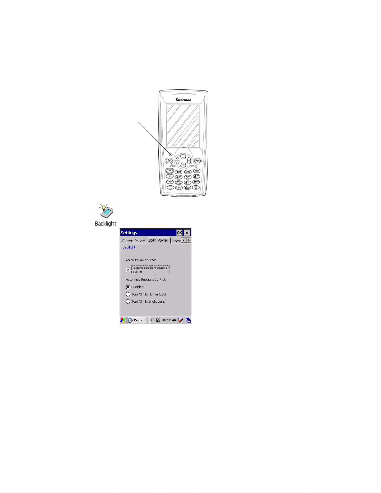
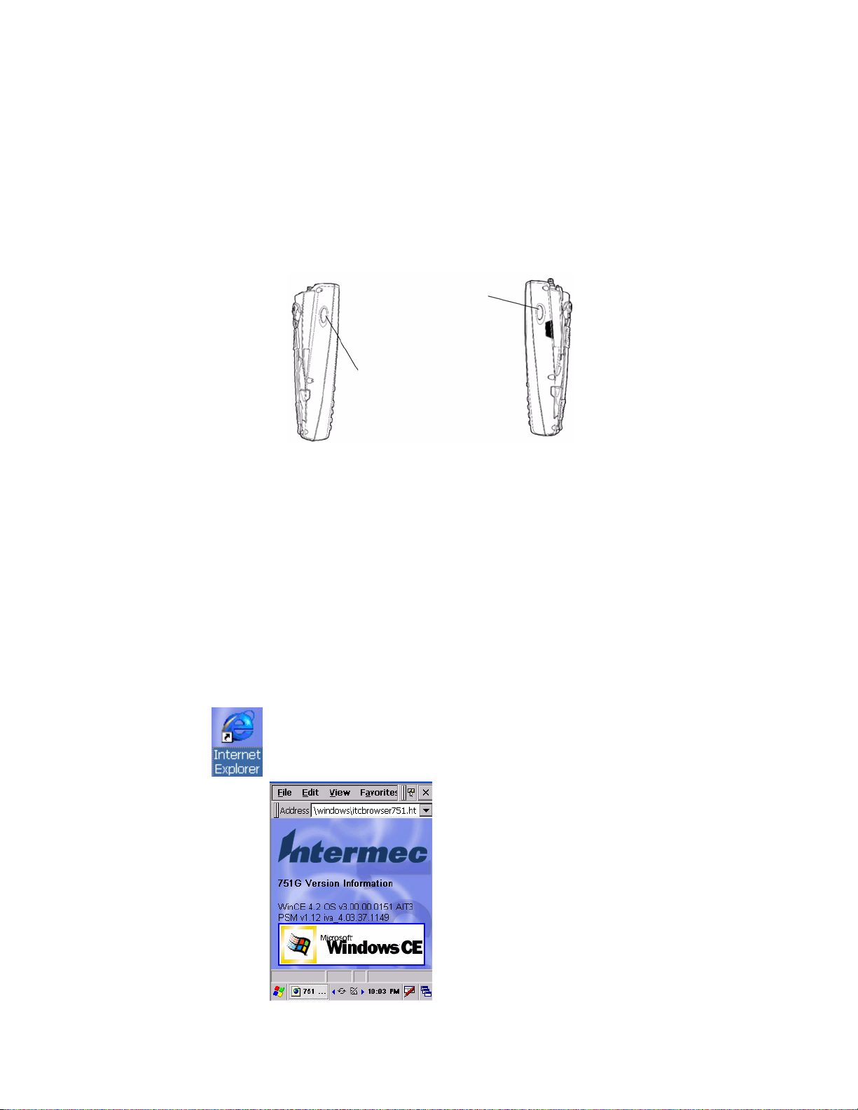
Ambient Light Sensor
The ambient light sensor turns on the display lighting when conditions
warrant but automatically turns if off again as surrounding light increases.
This conserves your 751G battery power.
Ambient Light
Sensor
To adjust the ambient light sensor, tap Start > Settings > Control Panel.
Double-tap the Backlight icon, then tap the right arrow to move to and tap
the Both Power tab. Make your selections, then tap OK to exit this applet.
2 751G Color Mobile Computer User’s Manual
Page 17
Audio System
Speaker
Chapter 1 — Using the Computer
The audio system consists of the speaker, internal microphone, and the
external headset jack.
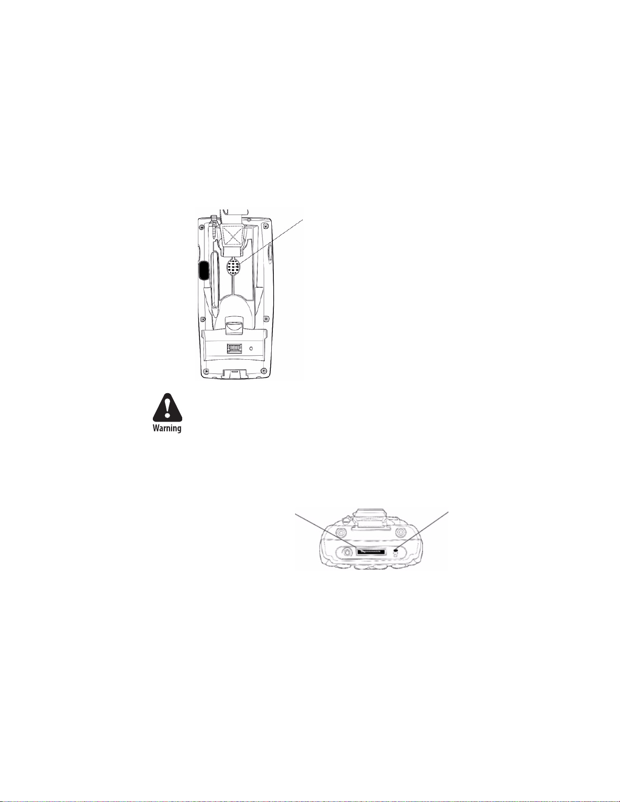
The speaker, which is capable of variable volume levels, is located on the
back of the 751G. This speaker has a transducer volume of 85 dB min at 10
cm (3.9") and a frequency range of 1-8 KHz.
Speaker
Microphone
Warning: Do not place the speaker next to your ear when the speaker
volume is set to “Loud” (maximum), or you may damage your hearing.
The built-in microphone is located on the bottom of the unit next to the
Hirose docking connector.
Hirose docking connector
This is the bottom of the 751G. Note that the keypad is to the bottom in this illustration.
Microphone
751G Color Mobile Computer User’s Manual 3
Page 18
Chapter 1 — Using the Computer
External Headset Jack
The external headset jack connects a mobile phone style headset to the
751G for use in noisy environments. The jack is a 2.5 mm, threeconductor jack, with autosensing of the headset jack insertion which
disables the internal speaker and microphone. The external headset jack is
located on the bottom of the 751G next to the Hirose docking connector.
Battery
External headset jack
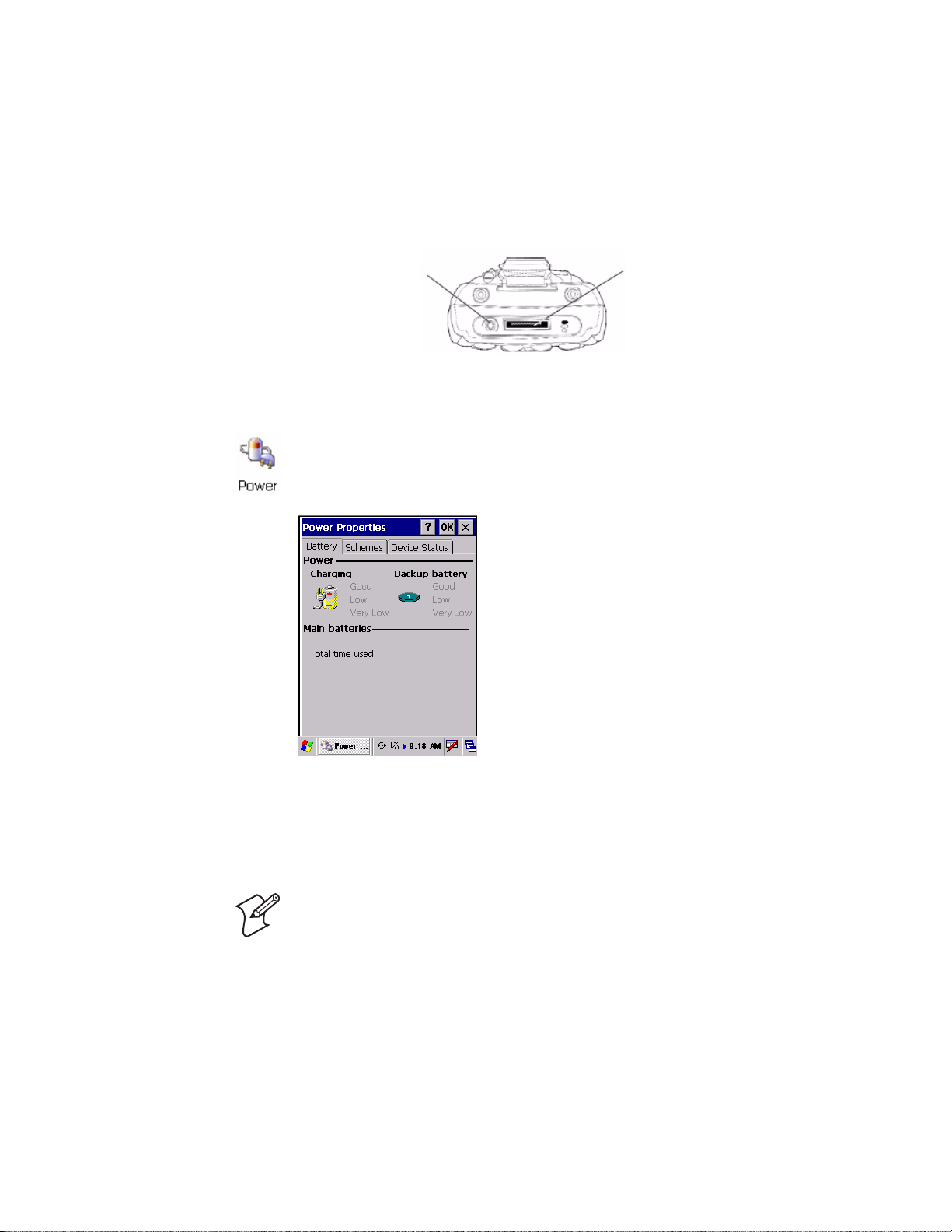
The 751G comes with a 14.4 Watt-hour, 7.2V, replaceable Lithium-Ion
(LiIon) battery. To view the status of this battery from the 751G, tap Start
> Settings > Control Panel. Double-tap the Power icon, then tap the
Battery tab. Tap OK to exit this applet.
Hirose docking connector
If your computer shuts down because of low battery conditions, your
computer does not operate. This is done to ensure that data is protected.
Although the battery does protect the data against loss for several hours,
you should connect your computer to a power source when you first detect
a low battery condition.
Note: Your computer has an internal backup super capacitor, a temporary
power storage device, that protects data for up to ten minutes. It also shuts
down the 751G if the main battery suddenly goes away (removed from the
computer). Depending on the processes running, it may not have adequate
power for a graceful shutdown. If so, the 751G performs a cold-boot the
next time power is applied.
In short, put the 751G into a suspend (sleep) mode before you remove
the main battery.
4 751G Color Mobile Computer User’s Manual
Page 19
If you have at least one device in your 751G (radio, scanner, or imager), the
battery power fail level is set so that after the system shuts down in a low
battery condition, there is still sufficient charge to allow the unit to remain
configured, keep proper time, and maintain DRAM (Dynamic Random
Access Memory) for at least 72 hours at room temperature if the main
battery remains in the mobile computer.
The configuration and time are lost if:
• The battery discharges beyond this level.
• The battery is removed when the computer is not in suspend mode.
• A cold-boot (reset) is performed on the computer.
Installing and Charging the Battery
Make sure you fully charge the battery before you use your 751G. To
charge the battery, you need to install it in the 751G.
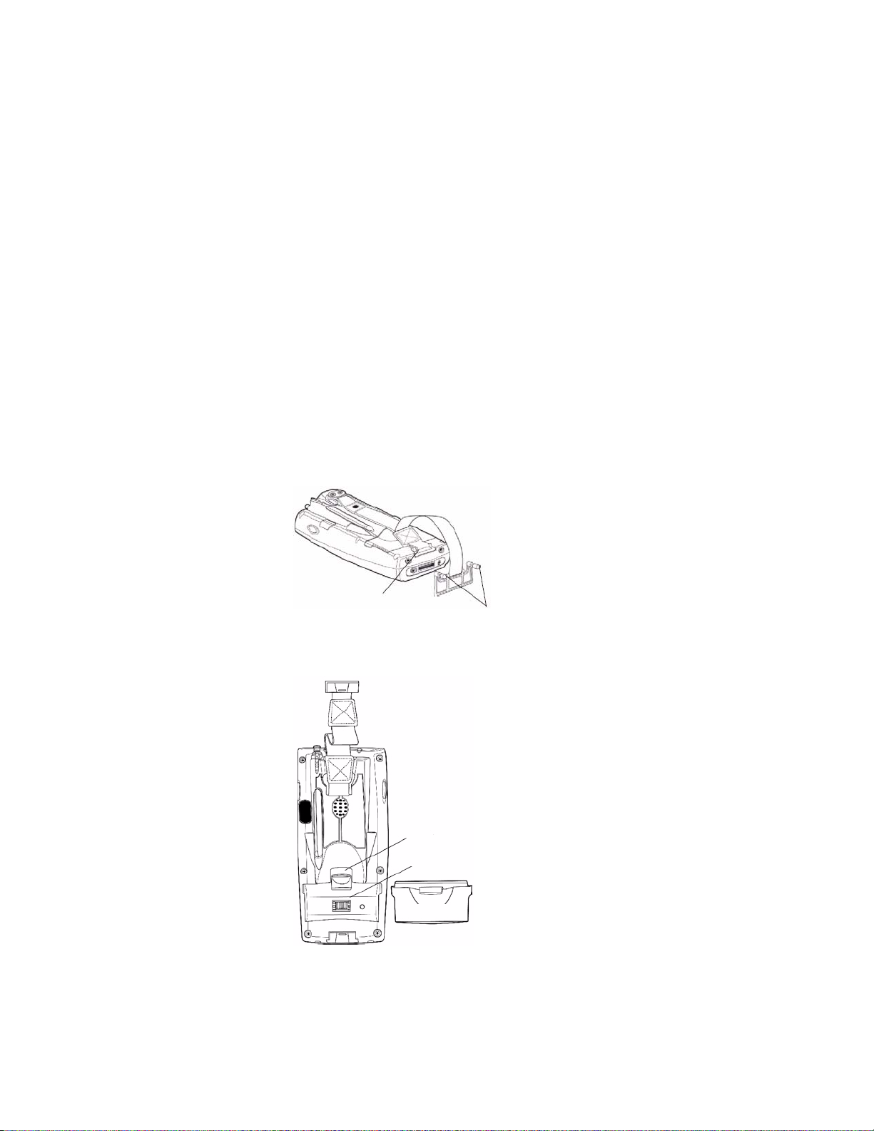
1 Remove the two thumb screws on the connector cover to release the
hand strap and back cover.
Chapter 1 — Using the Computer
2 Slide the bottom of the strap forward to release it from the retaining slot.
Retaining slot
Thumb screws
3 Tilt, insert, and place the battery into the compartment. Make sure the
battery compartment latch clicks in place to ensure the battery is secure.
Battery compartment latch
Battery compartment
Battery pack
4 Insert your 751G into its single dock for charging.
751G Color Mobile Computer User’s Manual 5
Page 20
Chapter 1 — Using the Computer
5 Charge the battery pack for three hours before using. However, to ensure
proper charging, perform the remaining steps first, with the AC adapter
or dock connected:
a The first time you turn on your 751G, it boots to the operating
b You will be prompted through the several screens to complete the
You must use only the Intermec power supply approved for use with
the 751G. Using any other power supply will damage the 751G.
Note: For help installing and using the single dock, see the 700 Series Single
Dock Quick Start Guide (P/N 962-040-009) shipped with the dock.
Removing the Battery
system. After a few seconds, you see the Windows CE .NET Desktop
screen. Tap your stylus to advance to the next display on the screen.
setup process. Read the display messages and follow the instructions.
When you reach the Windows CE .NET Desktop screen, you have
completed the setup.
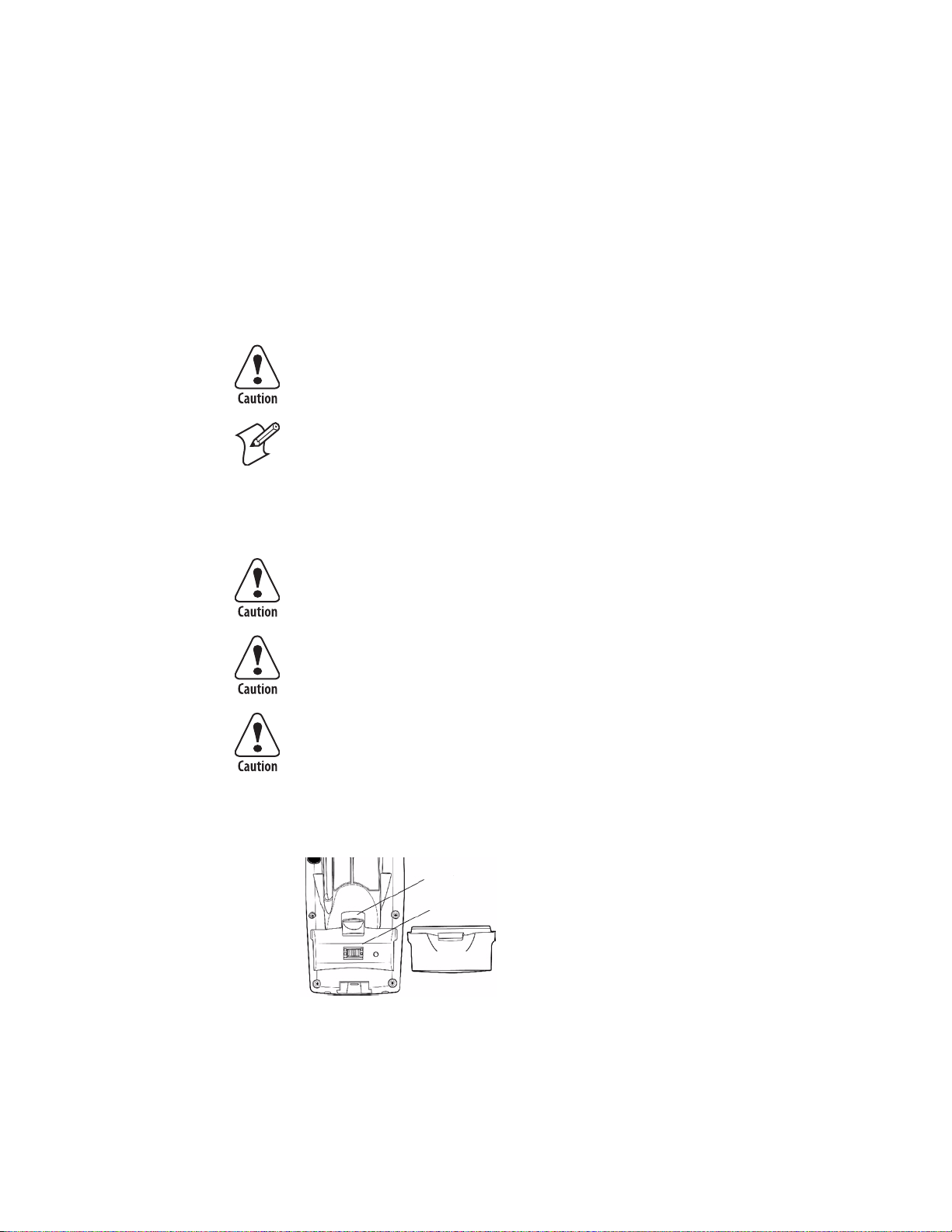
Follow these instructions to remove the battery from the 751G.
Only use the battery compartment latch to dislodge and remove the
battery. Using any other tool or method to remove the battery may
damage the battery or the 751G.
Removing the main battery when the backup battery low or critically
low icon appears on the status bar may cause your 751G to cold boot
and you may lose data.
If you fail to replace the battery immediately, you may lose important
data or applications.
To remove the battery
Pull up on the battery compartment latch, then lift the battery out of the
battery compartment.
Battery compartment latch
Battery compartment
Battery pack
6 751G Color Mobile Computer User’s Manual
Page 21
Maximizing Battery Life
•Set the Backlight Timeout to 10 seconds.
• Verify that Radio Power Management is enabled (Fast PSP). Enabling
radio power management allows your radio to switch between awake and
sleep modes based on network traffic.
• Verify that each setting under Power Management has a value of 1
minute for a combined automatic shutoff time of 3 minutes.
Beeper
Note: Each time a cold-boot is performed on the 751G, all default settings
are restored unless registry storage is enabled.
To learn how to set volume levels for screen taps, ActiveSync alert noises,
etc., tap Start > Help > Windows CE Basics.
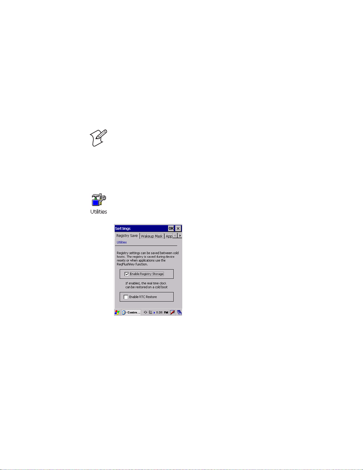
Enabling the Registry Storage
For Windows CE .NET, the Flash File System (PSM) is the only medium
available for saving the registry data. Tap Start > Settings > Control Panel.
Double-tap the Utilities icon, then tap the Registry Save tab. Check
Enable Registry Storage to enable this function, then tap OK.
Chapter 1 — Using the Computer
751G Color Mobile Computer User’s Manual 7
Page 22
Chapter 1 — Using the Computer
Enabling the Beeper
To enable the beeper:
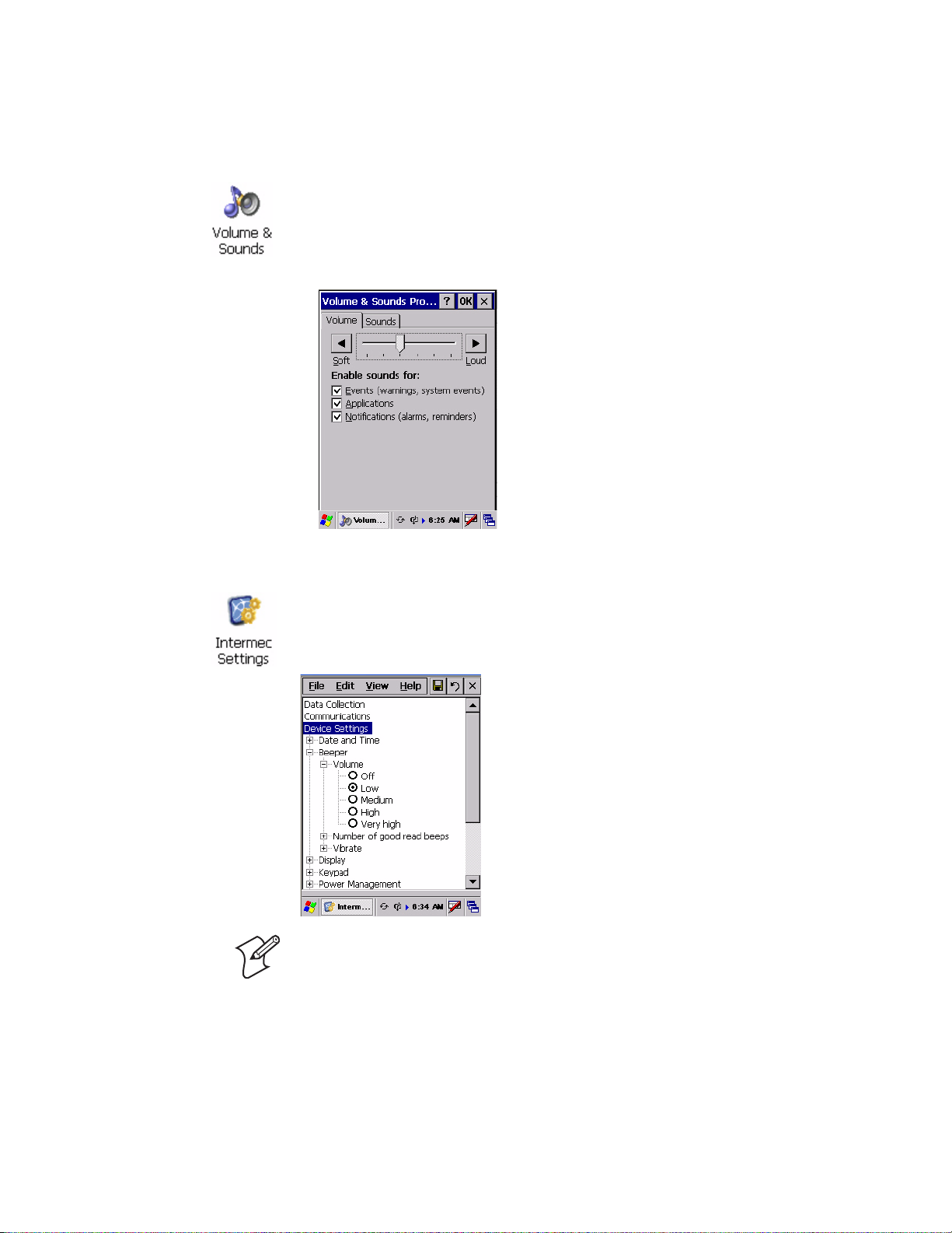
1 Tap Start > Settings > Control Panel. Double-tap the Volume &
Sounds icon, then tap the Volume tab.
2 Drag the slider bar to the right, away from the “Soft” position.
3 Tap OK to exit this applet.
Adjusting the Beeper Volume
To select a beeper volume for the 751G, tap Start > Intermec Settings,
then tap the Device Settings option. Tap (+) to expand the Beeper option,
then tap (+) to expand the Volume option. Select an item, then tap (+) to
close this option.
Note: Information about the Intermec Settings applet is found in the
Intermec Computer Command Reference Manual (P/N 073529). See your
Intermec representative for information.
8 751G Color Mobile Computer User’s Manual
Page 23
Disabling the Beeper
Chapter 1 — Using the Computer
To disable the beeper:
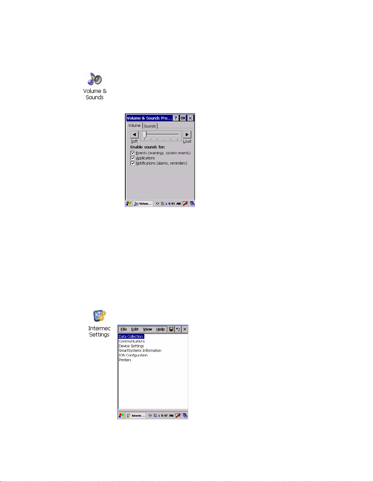
1 Tap Start > Settings > Control Panel. Double-tap the Volume &
Sounds icon, then tap the Volume tab.
2 Tap the Soft button to drag the slider bar all the way to the left.
3 Tap OK to exit this applet.
Intermec Settings Applet
Use the Intermec Settings applet to gather, view, and update device
configuration settings. Information about the settings you can configure
with the Intermec Settings applet is in the Intermec Computer Command
Reference Manual (P/N 073529) available online at www.intermec.com.
See the Data Collection Resource Kit in the Intermec Developer Library
(IDL) for information about data collection functions. The IDL is available
as a download from the Intermec web site at www.intermec.com/idl.
Contact your Intermec representative for more information.
Tap Start > Settings > Control Panel, then double-tap the Intermec
Settings icon to access the applet.
751G Color Mobile Computer User’s Manual 9
Page 24
Chapter 1 — Using the Computer
Keypad
Instructions for the keypad include the backlight and keypress sequences.
Backlight for Keypad
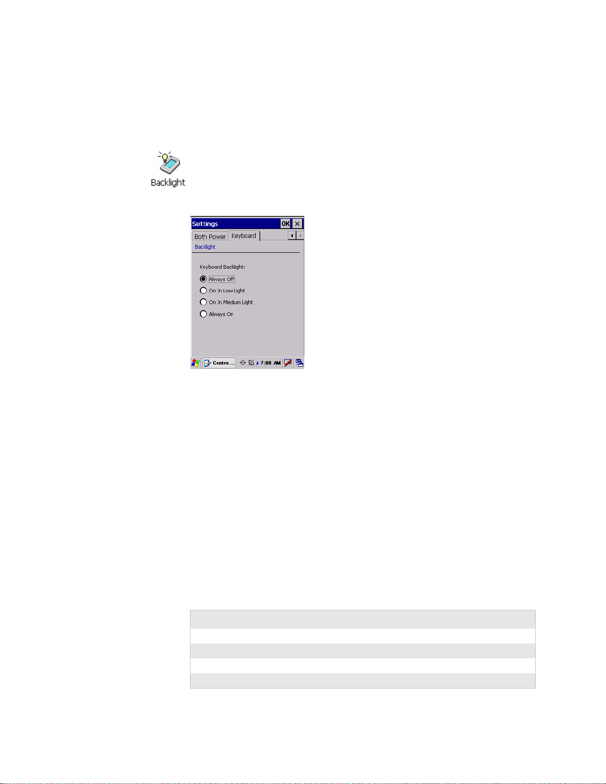
You can configure your keypad to turn on a backlight to assist you when
you are working in low lighting. To adjust the backlight for the keypad, tap
Start > Settings > Control Panel, then double-tap the Backlight icon. Tap
the right arrow to move to and tap the Keyboard tab. Make your selection,
then tap OK to exit this applet.
Key Sequences
Use the following key sequences to enter characters into your 751G using
the numeric keypad.
[Orange] Plane Keys
The [orange] plane key provides you access to display controls, special
characters, and CE .NET options.
Press the [orange] key for each orange plane key stroke you wish to make.
For example, to turn on the front light, press and hold the [orange] key
plus the [3]
The following table lists sequences that use the [orange] plane key. See
Chapter 2, “Windows CE .NET” for information about Windows CE
.NET applications.
[Orange] Plane Keys
Press the Keys To Do This
[orange] [3] Toggle backlight on/off, goes through backlight power levels
[orange] [.]
[orange] [4]
[orange] [5]
key. To turn the front light off, press these keys again.
10 751G Color Mobile Computer User’s Manual
Page 25

Chapter 1 — Using the Computer
[Orange] Plane Keys (continued)
Press the Keys To Do This
[orange] [6]
[orange] [7] Move up one page.
[orange] [8] Enter an asterisk (*).
[orange] [9] Move down one page.
[orange] [0] Access the CE .NET Start menu.
[orange] [Enter] Enter an at symbol (@).
[orange] [BkSp] Enter a backslash (/).
[orange] [Esc] Enter a minus sign (–).
[orange] [Action] Enter a plus sign (+).
[orange] [right arrow] Tab to the right.
[orange] [left arrow] Tab to the left.
[orange] [up arrow] Increase volume
[orange] [down arrow] Decrease volume
Alpha (Green) Plane Keys
You can enter the alphabet using the Alpha (green) plane keys. Below and
on the next page are the key sequences.
When you press [Alpha], the Scanning/Alpha LED shows red for the
Alpha mode. The keypad stays in Alpha mode until you press [Alpha]
again.
To type a lowercase “c,” press [Alpha] [2] [2] [2]. To type a letter on the
same key as the last letter entered, wait two seconds, then enter the correct
series of keystrokes to create the next letter.
While in the Alpha mode and you press [1] to initiate the CAPS mode, you
will render a CAPS LOCK until you press [1] again. Once you are in CAPS
mode, you stay in CAPS until it is pressed again. Press [0] to enter a space.
Alpha (Green) Plane Keys
To Enter Press the Keys To Enter Press the Keys
a [Alpha] [2] A [Alpha] [1] [2]
b [Alpha] [2] [2] B [Alpha] [1] [2] [2]
c [Alpha] [2] [2] [2] C [Alpha] [1] [2] [2] [2]
d [Alpha] [3] D [Alpha] [1] [3]
e [Alpha] [3] [3] E [Alpha] [1] [3] [3]
f [Alpha] [3] [3] [3] F [Alpha] [1] [3] [3] [3]
g [Alpha] [4] G [Alpha] [1] [4]
h [Alpha] [4] [4] H [Alpha] [1] [4] [4]
i [Alpha] [4] [4] [4] I [Alpha] [1] [4] [4] [4]
j [Alpha] [5] J [Alpha] [1] [5]
751G Color Mobile Computer User’s Manual 11
Page 26

Chapter 1 — Using the Computer
Alpha (Green) Plane Keys (continued)
To Enter Press the Keys To Enter Press the Keys
k [Alpha] [5] [5] K [Alpha] [1] [5] [5]
l [Alpha] [5] [5] [5] L [Alpha] [1] [5] [5] [5]
m [Alpha] [6] M [Alpha] [1] [6]
n [Alpha] [6] [6] N [Alpha] [1] [6] [6]
o [Alpha] [6] [6] [6] O [Alpha] [1] [6] [6] [6]
p [Alpha] [7] P [Alpha] [1] [7]
q [Alpha] [7] [7] Q [Alpha] [1] [7] [7]
r [Alpha] [7] [7] [7] R [Alpha] [1] [7] [7] [7]
s [Alpha] [7] [7] [7] [7] S [Alpha] [1] [7] [7] [7] [7]
t [Alpha] [8] T [Alpha] [1] [8]
u [Alpha] [8] [8] U [Alpha] [1] [8] [8]
v [Alpha] [8] [8] [8] V [Alpha] [1] [8] [8] [8]
w [Alpha] [9] W [Alpha] [1] [9]
x [Alpha] [9] [9] X [Alpha] [1] [9] [9]
y [Alpha] [9] [9] [9] Y [Alpha] [1] [9] [9] [9]
z [Alpha] [9] [9] [9] [9] Z [Alpha] [1] [9] [9] [9] [9]
LEDs
The battery status LED and the scanning/keypad shift and notification
LED turn red, green, or yellow.
Battery Status LED
LED Color and Action Description
Steady Green Battery is more than 95% charged and the 751G is on charger.
Blinking Red Battery is low. The blinking speed increases as the battery’s power gets increasingly lower.
Red Main battery is low; or if charging, remains red until the 95% charge status is reached.
Yellow The 751G is on a charging source and there is no battery pack installed. The mobile computer
may also be out of the charging range of 32° to 122° F (0° to 50° C). When back in range,
charging resumes and the LED changes to red or green.
Alternating Red/Yellow Replace the battery pack.
Scanning/Keypad Shift and Notification LED
LED Color/Action Description
Momentary Green
Blinking Green
Steady Red Indicates the keypad is shifted to the Alpha plane and the 751G is turned on.
Blinking Red Indicates the radio is on when in suspend mode and when the radio is initialized.
Yellow When the keypad is in Alpha mode, the LED temporarily switches from red to yellow to indicate a
Indicates the scanner has initialized and had a good scan.
Indicates the scanner is initializing.
good scan.
12 751G Color Mobile Computer User’s Manual
Page 27
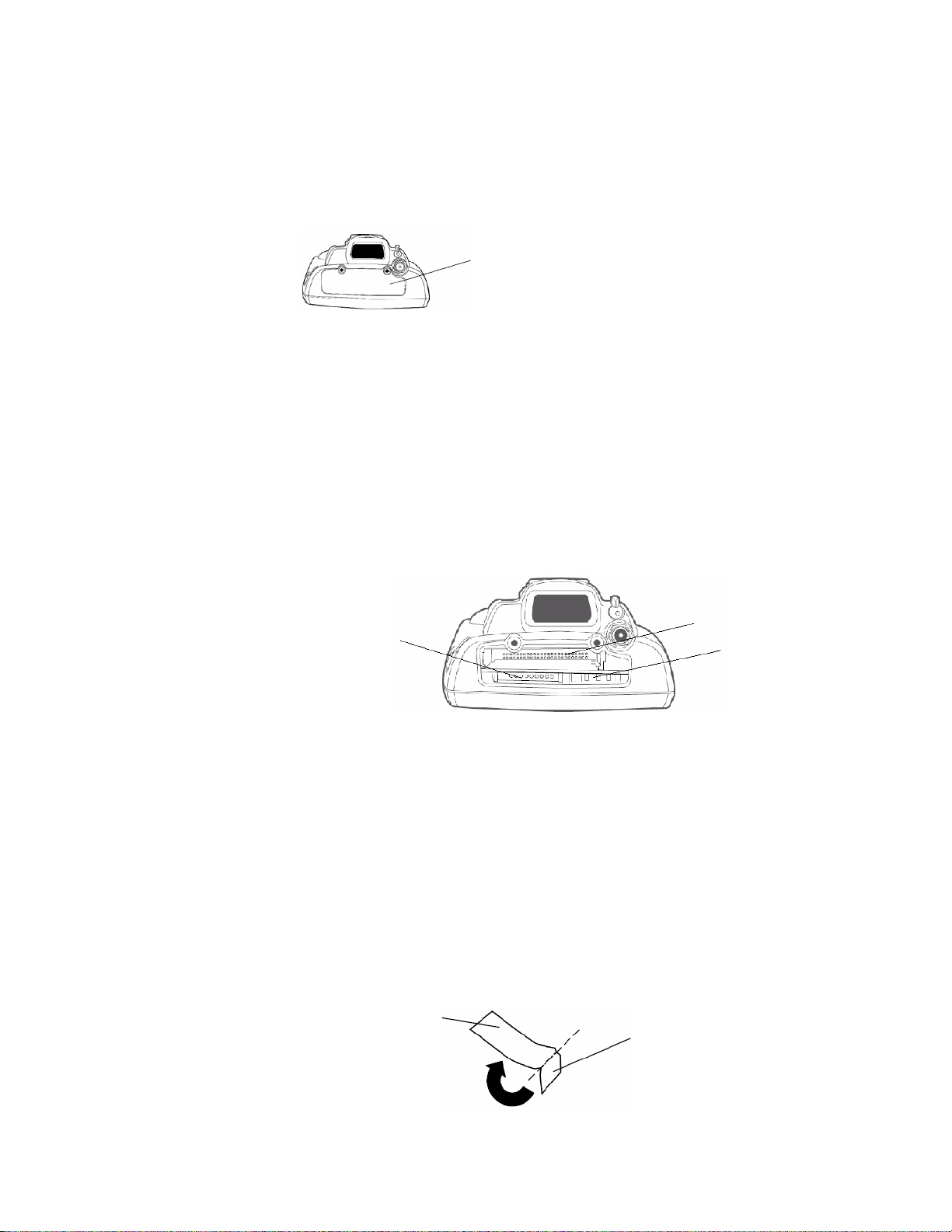
Resetting Your Computer
In some cases where the 751G completely stops responding, it may be
necessary to perform a cold reset. Because cold resetting may result in data
loss, only use this method if all other recovery methods have failed.
Note: Cold resetting deletes all programs and data stored in RAM
including the Object Store. Make sure data is backed up to your host
computer or a storage card before performing a cold reset.
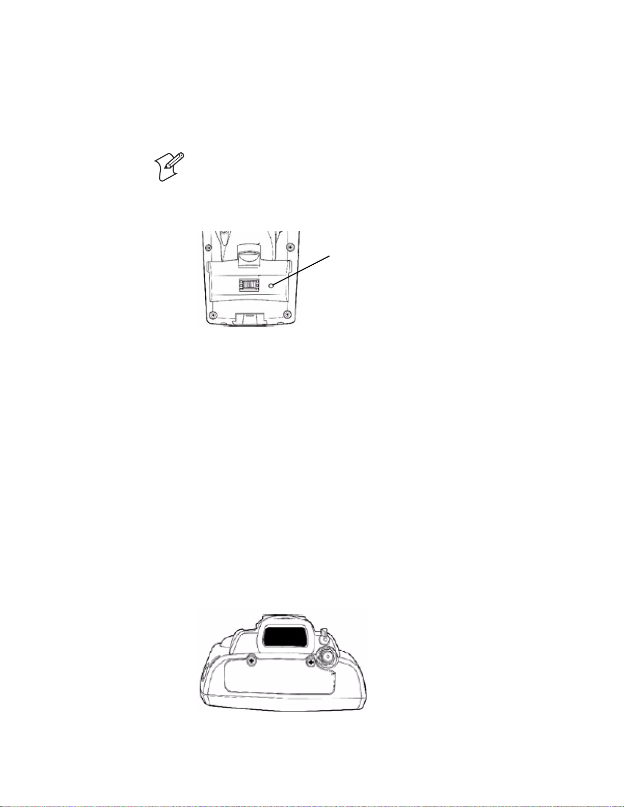
To reset your computer, release the lower clip of the hand strap, remove the
battery pack, press the Reset button, then reinstall the battery pack.
Chapter 1 — Using the Computer
Reset button
This illustration shows the back of the 751G inside the battery compartment.
Scanning Bar Codes
Use the area imager to scan and enter bar code data. The 751G supports
reading 1D and 2D images. These bar code symbologies are enabled by
default on the 751G: Code 39, Code 128, UPC-A, UPC-E, EAN-8, EAN13, and Datamatrix.
If you are using bar code labels that are encoded in a different symbology,
you need to enable the symbology on the computer. Use the Intermec
Settings applet to enable and disable symbologies. See the Intermec
Computer Command Reference Manual available from the Intermec web site
at www.intermec.com.
Scanning with the Area Imager
The 751G has an area imager on the top of the unit that can scan 1D and
2D bar code symbologies. It also supports omni-directional (360°)
scanning where you can position the unit in any orientation to scan a bar
code label. Using the 2D imager is like taking a digital picture.
751G Color Mobile Computer User’s Manual 13
Page 28
Chapter 1 — Using the Computer
To use the area imager
1 Press the power switch to turn on the 751G, point the scanner window a
few inches from the bar code label, and hold steady.
2 Press either Scan button and center the red aiming beam over the bar
code label. The aiming beam is smaller when the imager is closer to the
bar code and larger when it is further away.
3 When a bar code label is successfully read and a high beep is emitted,
release the Scan button you pressed.
Scan button on right
Scan or record button on left
Improving the Performance of the Area Imager
If you have problems scanning a bar code with the 2D imager, go to
“Improving the Performance of the Area Imager” on page 41 for tips on
improving its performance.
Software Build Version
The Persistent Storage Manager (PSM) is an area of storage which is
embedded in a section of the system’s FLASH memory. This storage area is
not erased during a cold-boot. It may, however, be erased during the
reflashing process. In addition to storing applications and data files, you do
have the option to store a persistent registry to the PSM region.
To check to see if your 751G has the latest PSM build or the latest CE
build, double-tap the Internet Explorer icon from the desktop, then scroll
down for the latest information displayed beneath the 751G Version
Information title.
14 751G Color Mobile Computer User’s Manual
Page 29

Chapter 1 — Using the Computer
Software Tools
The following Intermec software tools are available as free downloads:
SmartSystems Foundation Console (www.intermec.com/SmartSystems)
This tool includes a management console that provides a default method to
configure and manage Intermec devices “out-of-the-box,” without the
purchase of additional software licenses. This is for anyone who must
configure and deploy multiple devices or manage multiple licenses.
SmartSystems Platform Bundles (SSPB)
The SmartSystems Platform Bundle (SSPB) is a bundle of software that
contains the Data Collection Engine (DCE), SmartSystems, Funk
Supplicant, Intermec Settings, and Intermec Developer Library (IDL)
runtime.
The SSPB is stored in the “\Flash File Store” folder off the root of your
751G and automatically installed on the device when it is initially started
up. Updated bundles are available as software downloads from the Intermec
web site at www.intermec.com/SmartSystems. Click Downloads on the
left to access the latest.
Intermec Resource Kits (www.intermec.com/IDL)
Resource Kits provide tools that build applications using the features of
Intermec devices. Resource kits include: Bluetooth, Communications, Data
Collection, Device Settings, Mobile Gadgets, Printing, and RFID.
This is for anyone who develops software for the 751G.
Storage Media
Note: MultiMediaCards (MMCs) and CompactFlash (CF) storage cards
are not supported in 751G.
Note: The 751G currently supports Delkin Devices Secure Digital cards
only. Intermec Technologies cannot guarantee that other SD cards will
work with the 751G.
The 751G supports the Secure Digital storage card. Use the following
procedures to insert a Secure Digital card, access the files on a Secure
Digital card, and remove a Secure Digital card.
Warning: Before installing a Secure Digital card, inspect the gasket on
the door for any damage or wear, and replace the door if any damage or
wear is found. Otherwise, use of this terminal in a hazardous
environment may cause loss of life.
751G Color Mobile Computer User’s Manual 15
Page 30
Chapter 1 — Using the Computer
Accessing the Secure Digital Card Slot
To access the card slot, locate the access door at the top of the 751G, loosen
its two screws, then remove the door. Note that the screws to this door are to
be torqued to 1.5 in-lbs. See the Model 751G Mobile Computer Quick Start
Guide (P/N 962-054-093) for more information.
This illustration shows the top of the 751G. Note the keypad is to the bottom.
Internal Card Slots and Connector
Below is a view of the various card slots within your 751G. Note that you
only have access to the Secure Digital card slot. The other two slots are
embedded into the unit and cannot be removed.
• A radio is embedded in the CompactFlash card slot and is not accessible.
• The Secure Digital card goes into the bottom left card slot.
Storage Media Access Door
• The SmartCard adapter plugs into the 6-pin connector in the bottom
right.
Secure Digital card slot
This illustration shows the top of the 751G. Note the keypad is to the bottom.
Attaching a Tab to the Secure Digital Card
The Secure Digital storage card, as ordered from Intermec, come with
acrylic adhesive pull tabs. If you are using a storage card that you plan to
remove from the 751G, this tab can make its removal easier.
Do the following to attach the tab to your storage card. Note that the pull
tab has divots cut into either side, towards the shorter end. Use these divots
as a guide.
1 Completely peel the paper off the short end of the tab. Partially pull the
paper off the long end of the tab away from the divots. Fold the short
end under, at the divots, to stick to itself.
CompactFlash card slot
6-pin connector
Fold line at divotsLong end of pull tab
Short end of pull tab
16 751G Color Mobile Computer User’s Manual
Page 31

Chapter 1 — Using the Computer
2 Align the folded edge of the pull tab where there is no adhesive with the
bottom end of the storage card. Peel away the rest of the paper from the
long end, then firmly press down the remaining adhesive area of the tab
onto the storage card.
Align the folded end with this edge of the storage card
3 Insert the storage card, with the contacts facing the keypad, into your
751G to ensure that no adhesive is exposed once the tab is placed.
Keypad facing down
4 Press on the storage card until you hear a click. If needed, close the
storage media access door.
Accessing Files Stored on the Secure Digital Card
When inserted in the 751G, the Secure Digital card inserted in your 751G,
it appears as the “\SDMMC Disk” folder. To access this folder, select My
Computer, then tap the “\SDMMC Disk” folder.
Removing the Secure Digital Card
1 Press the Power key for seconds, and then release the Power key to turn
off the 751G. Remove the storage media access door.
2 Gently depress the Secure Digital card to release the card, then pull the
card from its slot.
3 Replace the storage media access door.
4 Press the Power key for two to three seconds, and then release the Power
key to turn on the 751G.
Wireless Network Support
Radios are installed at the factory and cannot be installed by a user. The
751G must be serviced to install or replace radios. Contact your Intermec
representative for more information. See Chapter 5, “Network Support”
for information about supported radios.
Note: Changes or modifications not expressly approved by Intermec could
void the user’s authority to operate the equipment.
751G Color Mobile Computer User’s Manual 17
Page 32

Chapter 1 — Using the Computer
Accessories
The following accessories are available for the 751G. Note that this is not a
complete list. Contact your Intermec representative for information about
these and other accessories that are not in this list.
Communications and charging dock
Single bay communications cradle with serial/USB/O interface
USB through multipurpose connector at base of unit or RS232 serial adapters
Serial/USB cables
Snap-on module for button memory
CAC (Common Access Card) adapter
Plug-in interface CAC reader
4-slot battery charger
Pistol grip scanning handle
Holster
Dust cover
Physical and Environmental Specifications
Use these specifications to locate technical information about the 751G
and its available features and options.
Display
1/4 VGA Transflective, software-controlled backlight
Pixels: 240x320
Diagonal: 97 mm (3.8 in)
Colors: 256 K
Environmental
Operating Temperature: -10° to 50°C (14° to 122°F)
Storage Temperature: -20° to 60°C (-4° to 140°F)
Relative Humidity: 5% to 95% noncondensing
Rain and Dust Resistance: IP64 compliant
Drop Specifications: 1.2 m (4 ft) drop
Secure Digital Expansion Slots
The 751G supports the Delkin Devices Secure Digital storage card.
Integrated Scanner Options
EA11 Linear Imager
Integrated Wireless
802.11b/g (Wi-Fi® certified): WLAN (802.11b/g)
Bluetooth™ compatible module
18 751G Color Mobile Computer User’s Manual
Page 33

Chapter 1 — Using the Computer
Keypad Option
22-key layout with one-touch numerics and shifted alpha with 4-way
navigation buttons
Memory and Storage
RAM Memory: 64 MB
Flash ROM: 64 MB, includes ROM folder for application storage
Microprocessor
Intel® XScale™ PXA255 Application Processor, 400 MHz
Operating System
Microsoft® Windows® CE .NET (4.2)
Physical Dimensions
Length: 191 mm (7.53 in)
Width: 50 mm (1.97 in)
Height: 90 mm (3.50 in)
Weight: 460 g (16.0 oz)
Power
Battery Type: Lithium-Ion (LiIon), 7.2V, (1x2000 mAh cells),
customer-replaceable
Battery Capacity: 14.4 Watt-hours
Battery Life: 8+ hours, application-dependent
Recharging Time: 4 hours
Charging Range: 0° to 40°C (32° to 104°F)
Regulator Approvals
UL and cUL Listed, UL 60950 and UL 1604 and CSA 22.2 #157, FCC
Part 15, TUV, CE mark
Standard Communications
RS232; USB
751G Color Mobile Computer User’s Manual 19
Page 34

Chapter 1 — Using the Computer
20 751G Color Mobile Computer User’s Manual
Page 35

Windows CE .NET
2
This chapter introduces Microsoft Windows CE .NET. While using your
751G Mobile Computer, keep this key point in mind:
Tap Start on the task bar, located at the bottom, left corner of the screen, to
quickly move to programs, files, and settings. Use the task bar at the
bottom of the screen to perform tasks in programs. The task bar includes
menus, buttons, and the onscreen keyboard.
Note: Desktop icons and applet icons are shown to the left. Any place that
Start is mentioned, tap the following Windows icon in the bottom, left
corner of your desktop.
751G Color Mobile Computer User’s Manual 21
Page 36

Chapter 2 — Windows CE .NET
Software Builds
Go to “Software Build Version” on page 14 to determine which Intermec
build is on your unit.
Where to Find Information
This chapter describes your 751G CE. NET applications, and explains how
to connect your 751G to a PC, a network, or the Internet. Below is a guide
to assist you in using your 751G.
For information on: See this source:
Programs on your mobile computer. This chapter and mobile computer Help. To view Help, tap
Start > Help.
Additional programs that can be installed on the
mobile computer.
Connecting to and synchronizing with a PC. The Quick Start Guide or ActiveSync Help on your PC.
Last-minute updates and detailed technical
information.
Up-to-date information on your Windows CE .NET
device.
The Windows CE .NET Companion CD.
The Read Me files, located in the Microsoft ActiveSync folder on
the PC and on the Windows CE .NET Companion CD.
msdn.microsoft.com/embedded/downloads/ce/default.aspx
Basic Skills
Use these URLs for additional information about Microsoft Windows CE
.NET:
• msdn.microsoft.com/support
• support.microsoft.com
• www.microsoft.com/technet/community/newsgroups/security/
default.mspx (a free support option)
Learning to use your 751G is easy. This section describes the basic concepts
of using and customizing your 751G.
22 751G Color Mobile Computer User’s Manual
Page 37

Desktop Screen
Chapter 2 — Windows CE .NET
When you turn on your 751G for the first time each day, you see the
Desktop screen.
Tap to use the Start menu
Tap to open an associated program
To customize what is displayed on the Desktop screen, including the
background image, tap Start > Settings > Control Panel, then double-tap
the Display icon.
Status icons display information such as low batteries or when the 751G is
connected to a PC or to the Internet. You can tap an icon to open the
associated setting or program.
Programs
You can switch from one program to another by selecting it from the Start
menu. (You can customize which programs you see on this menu. For
information, see “Adjusting Settings” on page 27.) To access some
programs, tap Start > Programs, and then the program name.
Start Menu and Task Bar
The Start Menu is located at the bottom of the screen. It displays the active
program, and allows you to switch to programs and close screens.
Tap to scroll to other programs
Tap to list open windows
Tap to activate the input panel
Double-tap to change time format
Tap to access the Intermec Settings applet
Tap to see more programs
Tap to see web sites or WAP pages
Tap to see text files and other documents
Tap to configure your unit
Tap to display the input panel
The task bar, which displays the current time, is at the bottom of the
screen. The task bar includes menu names, buttons, and the Input Panel
icon. Use this task bar to perform tasks in programs.
751G Color Mobile Computer User’s Manual 23
Page 38

Chapter 2 — Windows CE .NET
Notifications
When you have something to do, your device notifies you in any of the
following ways. You can choose notification types.
• A message box appears on the screen.
• A sound, which you can specify is played.
• A light flashes on your 751G.
Entering Information
You can enter information on your 751G in several ways, depending on the
type of device you have and the program you are using:
Use the input panel to enter information in any program on your 751G.
You can either type using the onscreen keyboard or write using
Transcriber. The characters appear as typed text on the screen.
Typing Enter typed text into the 751G. You can do this by tapping keys on the
onscreen keyboard or by using handwriting recognition software.
Writing Using the stylus, write directly on the screen.
Drawing Using the stylus, draw directly on the screen.
To show the input panel, tap the Input Panel icon, then tap Keyboard. To
hide the input panel, tap the Keyboard icon, then tap Hide Input Panel.
Tap to display the soft keyboard
Input Panel icon
Typing With the Onscreen Keyboard
Tap the stylus input icon, then tap Keyboard. On the soft keyboard that is
displayed, tap the keys with your stylus.
• To type lowercase letters, tap the keys with the stylus.
• To type a single uppercase letter or symbol, tap the Shift key. To tap
multiple uppercase letters or symbols, tap the CAP key. Note that the
CAP key only appears if the keyboard is set to small keys.
• To convert to uppercase, tap and hold the stylus on a letter and drag up.
• To add a space, drag the stylus to the right across at least two keys.
• To backspace, drag the stylus to the left across at least two keys.
• To insert a carriage return, tap and hold the stylus anywhere on the
keyboard and drag down.
24 751G Color Mobile Computer User’s Manual
Page 39

Chapter 2 — Windows CE .NET
If you want to use larger keys, tap Start > Settings > Control Panel, then
double-tap the Input Panel icon. Tap Options, then select Large keys. Tap
OK, then OK again to close the Input Panel properties.
Using Transcriber
With Transcriber, you can write on the screen with the stylus just as you
would on paper. You can write a sentence or more of information, then
pause and let Transcriber change written characters to typed characters.
For specific instructions on using Transcriber, double-tap the Transcriber
shortcut on the desktop screen, then tap Help. Tap OK to close the
Transcriber Intro box.
To enable the Transcriber feature, tap the Transcriber icon on the task bar,
then write anywhere on the screen. Note the gray box behind the icon. The
input then appears in the active window. To disable the Transcriber, tap
the Transcriber icon again. This removes the gray box in the background.
Transcriber icon
Selecting Typed Text
If you want to edit or format typed text, you must select it first.
• Drag the stylus across the text you want to select.
You can cut, copy, and paste text by tapping and holding the selected words
and then tapping an editing command on the pop-up menu, or by tapping
the command on the Edit menu.
751G Color Mobile Computer User’s Manual 25
Page 40

Chapter 2 — Windows CE .NET
Finding and Organizing Information
Use Windows Explorer to find and organize files into folders on the 751G.
To open Windows Explorer
1 Tap Start > Programs > Windows Explorer.
2 Double-tap any folder to open it.
3 Move files by tapping and holding the items you want to move, then tap
either Cut or Copy and Paste on the pop-up menu.
Double-tap a folder to open it
You can also use the System applet to pull up a list of active programs
currently running on your 751G.
To start Task Manager
1 Tap Start > Settings > Control Panel, then double-tap the System icon.
2 Tap the Memory tab, then tap Active Programs for the Task Manager.
26 751G Color Mobile Computer User’s Manual
Page 41

To use a different application, select an application, then tap Switch To.
To stop an application, select that application, then tap End Task.
Customizing Your Computer
You can customize your 751G by adjusting settings and installing software.
Adjusting Settings
You can adjust settings to suit the way you work. To see available options,
tap Start > Settings > Control Panel, then double-tap any of the applets.
You might want to adjust the following:
Chapter 2 — Windows CE .NET
Date/Time
To change the time or calendar.
Display
To customize the look of the desktop.
Owner
To enter your contact information.
Password
To limit access to your 751G.
Power
To maximize battery life.
Adding or Removing Programs
Programs added to your 751G at the factory are stored in ROM (Read
Only Memory). You cannot remove this software, and you cannot
accidentally lose ROM contents. All other programs and data files added to
your 751G after factory installation are stored in RAM (Random Access
Memory).
751G Color Mobile Computer User’s Manual 27
Page 42

Chapter 2 — Windows CE .NET
You can install any program created for your 751G, as long as your 751G
has enough memory. The most popular place to find software for your
751G is on the Windows CE .NET web site (msdn.microsoft.com/
embedded/downloads/ce/default.aspx).
Adding Programs Using Microsoft ActiveSync
Install applicable software on your PC before installing it on the 751G.
1 Determine your 751G and processor type so that you know which
version of the software to install. Tap Start > Settings > Control Panel,
then double-tap the System icon. Note the processor information on the
General tab beneath the Computer heading.
2 Download the program to your PC (or insert the CD or disk that
contains the program into your PC). You may see a single *.EXE or
*.ZIP file, a SETUP.EXE file, or several versions of files for different
751G types and processors. Be sure to select the program designed for
the Windows CE .NET and your 751G processor type.
3 Read any installation instructions, Read Me files, or program
documentation. Many programs provide special installation instructions.
4 Connect your 751G and PC.
5 Double-click the *.EXE file.
• If the file is an installer, the installation wizard begins. Follow the
directions on the screen. Once the software is installed, the installer
automatically transfers the software to your 751G.
• If the file is not an installer, an error message stating that the program
is valid but it is designed for a different type of computer is displayed.
Move this file to your 751G. If you cannot find any installation
instructions for the program in the Read Me file or documentation,
use Microsoft ActiveSync Explore to copy the program file to the “My
Computer\Program Files” folder on your 751G. For information on
copying files using Microsoft ActiveSync, see ActiveSync Help.
Once installation is complete, tap Start > Programs, and then the program
icon to switch to it.
28 751G Color Mobile Computer User’s Manual
Page 43

Chapter 2 — Windows CE .NET
Adding a Program Directly from the Internet
1 Determine your 751G and processor type so that you know which
version of the software to install. Tap Start > Settings > Control Panel,
then double-tap the System icon. Note the processor information on the
General tab beneath the Computer heading.
2 Download the program to your 751G straight from the Internet using
Internet Explorer. You may see a single *.EXE or *.ZIP file, a
SETUP.EXE file, or several versions of files for different 751G types and
processors. Be sure to select the program designed for the Windows CE
.NET and your 751G processor type.
3 Read program installation instructions, Read Me files, or other
documentation. Many programs provide installation instructions.
4 Tap the file, such as *.EXE file to start the installation wizard. Follow the
directions on the screen.
Adding a Program to the Start Menu
You can either use Windows Explorer on the 751G to move the program to
the “\My Computer\Windows\Start Menu” folder, or use Microsoft
ActiveSync on the PC to create a shortcut to the program and place the
shortcut in the “\My Computer\Windows\Start Menu” folder.
Using Windows Explorer on the Computer
Tap Start > Programs > Windows Explorer, and locate the program. Tap
and hold the program and tap Cut on the pop-up menu. Open the
“\My Computer\Windows\Start Menu” folder, tap and hold a blank area
of the window, and tap Paste on the pop-up menu. The program now
appears on the Start menu. For more information on using Windows
Explorer, see “Finding and Organizing Information” on page 26.
Using Microsoft ActiveSync on the PC
Use the Explore in Microsoft ActiveSync to explore your 751G files and
locate the program. Right-click the program, and then click Create
Shortcut. Move the shortcut to the “\My Computer\Windows\Start
Menu” folder. The shortcut now appears on the Start menu. For more
information, see ActiveSync Help.
Removing Programs
Tap Start > Settings > Control Panel, then double-tap the Remove
Programs icon.
If the program does not appear in the list of installed programs, use
Windows Explorer on your 751G to locate the program, tap and hold the
program, and then tap Delete on the pop-up menu.
751G Color Mobile Computer User’s Manual 29
Page 44

Chapter 2 — Windows CE .NET
Microsoft ActiveSync
Tap Start > Settings > Control Panel, then double-tap the PC
Connection icon. Tap Change Connection, then select the baud rate
from the drop-down list.
Visit the following Microsoft web site for the latest in updates, technical
information, and samples:
msdn.microsoft.com/embedded/downloads/ce/default.aspx
With Microsoft ActiveSync, you can back up and restore your 751G data,
and copy files between your 751G and PC.
Install Microsoft ActiveSync on the desktop of your PC from the following
URL. For more information, on installing Microsoft ActiveSync, see your
Quick Start card. ActiveSync is already installed on your 751G.
After installation is complete, the Microsoft ActiveSync Setup Wizard helps
you connect your 751G to your PC or set up a partnership so you can
browse for or move information between your 751G and your PC.
Disconnect the 751G from your PC and you are ready to go!
Note: While Microsoft ActiveSync does synchronize files between your PC
and your 751G, the 751G does not support applications such as Calendar,
Contacts, Tasks, Inbox, Channels, and Pocket Access.
Microsoft WordPad
WordPad works with Microsoft Word on your desktop to access copies of
your documents. You can create new documents on your 751G, or you can
copy documents from your desktop to your 751G. Synchronize documents
between your desktop and your 751G to have up-to-date content in both
locations.
To access WordPad, either double-tap the Microsoft WordPad icon on
your desktop, or select Start > Programs > Microsoft WordPad.
For more information on using Microsoft WordPad, select Start > Help >
WordPad.
msdn.microsoft.com/downloads/
30 751G Color Mobile Computer User’s Manual
Page 45

Creating a Document
Chapter 2 — Windows CE .NET
Use WordPad to create documents, such as letters or meeting minutes. To
create a new file, tap File > New, then select either a blank document or a
template, depending on what you have selected in the Tools > Options
dialog box. Select an input mode from the View menu.
You can open only one document at a time; when you open a second
document, you have to save the first. Documents you create or edit are
usually saved as WordPad (.WPD), but you can also save documents in
other formats such as Word (.DOC) or Rich Text Format (.RTF).
Windows Explorer contains a list of files stored on your 751G. Double-tap
a file to open it. To delete, make copies of, and rename files, tap and hold a
file in the list, then, select the action on the pop-up menu.
Tap any of the headers to change the order of the list
Double-tap to open a document
Press and hold a document to see its pop-up menu
Typing Mode
You can change the zoom magnification by tapping View > Zoom, then
select the percentage you want. Select a higher percentage to enter text and
a lower one to see more of your document.
If you are opening a Word document created on a desktop, you may select
View > Wrap to Window so that you can see the entire document.
To check spelling, select text, then tap Tools > Spell Check. To use your
new document as a template, move the document to the Templates folder.
Using the input panel, enter typed text into the document. For more
information on entering typed text, see “Entering Information” on
page 24.
To format existing text and to edit text, first select the text. You can select
text as you do in a Word document, using your stylus instead of the mouse
to drag through the text you want to select. You can search a document to
find text by tapping Edit > Find.
751G Color Mobile Computer User’s Manual 31
Page 46

Chapter 2 — Windows CE .NET
Writing Mode
With Transcriber enabled, use your stylus to write directly on the screen.
The zoom magnification is greater than in typing mode to allow you to
write more easily. For more information on writing and selecting writing,
see “Entering Information” on page 24.
Tap to return to the document
Tap to hide or show the keypad
Transcriber enabled
Synchronizing WordPad Documents
WordPad documents can be synchronized with Word documents on your
desktop. To synchronize files, first select the Files information type for
synchronization in ActiveSync. When you select Files, the My Documents
folder for the 751G is created on your desktop. Place all files you want to
synchronize with the device in this folder. Password-protected files cannot
be synchronized.
All WordPad files stored in My Documents and its subfolders are
synchronized with the desktop. ActiveSync converts documents during
synchronization.
For more information on synchronization or file conversion, see ActiveSync
Help on the desktop.
32 751G Color Mobile Computer User’s Manual
Page 47

Internet Explorer
Chapter 2 — Windows CE .NET
Note: When you delete a file on either your desktop or your 751G, the file
is deleted in the other location when you synchronize.
Use Microsoft Internet Explorer to view web sites or WAP pages. To do
this, create the connection first via an ISP or network, as described in
“Connecting to an Internet Service Provider” on page 113.
When connected to an ISP or network, you can also download files and
programs from the Internet or intranet.
To switch to Internet Explorer on your 751G, double-tap the Internet
Explorer icon on your desktop or select Start > Programs > Internet
Explorer to access the application
Viewing Mobile Favorites and Channels
1 Tap Favorites from the tool menu to display your list of favorites.
2 Tap the page you want to view.
Tap to add or delete a folder or favorite link
Tap the favorite to view
Browsing the Internet
1 Set up a connection to your ISP or corporate network using information
as described in “Connecting to an Internet Service Provider” on
page 113.
751G Color Mobile Computer User’s Manual 33
Page 48

Chapter 2 — Windows CE .NET
2 To connect and start browsing, either tap Favorites from the toolbar,
then tap the favorite to view, or in the Address bar that appears at the
top of the screen, enter the web address you want to visit using the input
panel, then tap the [Enter] key on the panel to go to that web site.
Tap the drop-down arrow to select from previously entered addresses.
Tap to bring down a list of addresses
Note: To add a favorite link while using the 751G, go to the page you want
to add, select Favorites > Add to Favorites.
34 751G Color Mobile Computer User’s Manual
Page 49

Configuring the Computer
3
There are multiple ways to get an application to your 751G Mobile
Computer; like there are multiple ways to package the application for
delivery.
Note: Desktop icons and applet icons are shown to the left. Any place that
Start is mentioned, tap the following Windows icon in the bottom, left
corner of your desktop.
751G Color Mobile Computer User’s Manual 35
Page 50

Chapter 3 — Configuring the Computer
Configuring Parameters
You can configure many parameters on the 751G, such as the bar code
symbologies it decodes or the network settings. These characteristics are
controlled by configuration parameters. The values you set for these
configuration parameters determine how the computer operates. Use
configuration commands to configure the 751G.
Configuring the Computer With Intermec Settings
Use the Intermec Settings applet to configure the 751G and view system
information. You can access the Intermec Settings applet while running any
application.
From the 751G desktop, select Start > Settings > Control Panel, then
double-tap the Intermec Settings icon.
For detailed information on most of the commands available in the
Intermec Settings applet, see the Intermec Computer Command Reference
Manual (P/N 073529) via the Intermec web site. Go to “Before You
Begin” for access information.
Synchronizing the Computer System Time with a Time Server
It is important that the time on all of your 751Gs be synchronized with a
network time server to ensure real-time communications and updates.
Network time servers acquire Coordinated Universal Time (UTC) from an
outside source such as the U.S. Naval Observatory (USNO). The 751G
uses Simple Network Time Protocol (SNTP) to synchronize with a
network time server.
The default reference time server is the USNO (tock.usno.navy.mil). To
synchronize the time on your 751G with this time server, you must have a
valid connection to the Internet. You can also synchronize the 751G system
time with a corporate network server within your firewall that is SNTPcapable. To use an internal corporate network server, you need to set the
command name in the registry.
36 751G Color Mobile Computer User’s Manual
Page 51

Configuring the Computer through the Network
You can change the configuration parameters of the 751G by sending
commands through a host computer or through the network. If you are
using a network, you can configure one or more 751Gs at a time. You can
remotely configure the wireless 751G by sending a command from an
application on the host computer. Note that you cannot set all parameters
through the network. You can only set those commands that have a syntax in the
Intermec Computer Command Reference Manual.
Note: You can continue running an application on the 751G while
configuring it from the host computer.
Configuring the Computer in a TCP/IP Direct Connect Network
Use the host computer to configure a wireless 751G in a
TCP/IP network. To send and receive configuration data, write a host
application that can communicate with the 751G directly through an
access point or through the network. Use the TMF protocol to send and
receive transactions between the host application and the 751G.
To set up the host computer, verify communication with the 751G. To set
up the application, prepare and write a host application that can
communicate with the IAS and send transactions to and receive
transactions from the 751G in this format:
Chapter 3 — Configuring the Computer
TMF field commands
where:
TMF field is a 2-byte field containing one of these values:
CG Configuration Get request sent from the host application.
Cg Configuration Get response sent from the 751G to the host computer.
CS Configuration Set request sent from the host application.
Cs Configuration Set response sent from the 751G to the host computer.
commands are the reader and configuration commands to set on the 751G or the current
value to retrieve from the 751G. To save configuration changes in flash
memory, send the .+1 reader command as the last command. See the
Intermec Computer Command Reference Manual for a list of commands.
Example
In the host application, you want to get the current values of two
configuration commands from the 751G. Send the
CG$+NABV transaction
from the host application.
Note: The transaction header is not shown in this example. You do not
need a transaction header for a host application in a TCP/IP network, but
you do for a UDP Plus network.
where:
CG is a TMF Configuration Get request.
$+ is the Change Configuration reader command.
BV is the Beeper Volume configuration command.
751G Color Mobile Computer User’s Manual 37
Page 52

Chapter 3 — Configuring the Computer
The computer returns the CgS+BV4 transaction to the host application:
Cg is a TMF Configuration Get response.
$+ is the Change Configuration reader command.
BV4 means the Beeper Volume configuration command is set to a value of 4, which is
a very high beeper volume.
Configuring the Computer in a UDP Plus Network
Use the host computer to configure a 751G in your wireless network. To
send and receive configuration data or files, write a host application that
can communicate with an Intermec Application Server (IAS) (formerly
Gateway or DCS 30X).
For help, see the appropriate Gateway or DCS 30X User’s Manual. Use the
Terminal Message Format (TMF) protocol to send and receive transactions
between the host application and the 751G.
To set up the IAS, configure a peer-to-peer destination name for the host
application. Create a $NGCFGRSP transaction ID that routes to this
destination name. The IAS uses the transaction ID to route responses from
the 751G back to the host application. $NGCFGRSP is a special
transaction ID that the server uses to forward configuration response data
from a 751G.
All configuration responses are routed with the $NGCFGRSP transaction
ID. The IAS cannot track multiple applications sending reader or
configuration commands. If you have two host applications sending reader
or configuration commands, they must both be configured to receive the
$NGCFGRSP transactions, and receive all 751G responses.
To set up the host computer, verify host computer-to-IAS communication.
To set up the application, prepare and write a host application that can
communicate with the IAS and send transactions to and receive
transactions from the 751G in this format.
transaction header TMF field commands
where:
transaction
header
TMF field is a 2-byte field containing one of these values:
commands are the reader and configuration commands to set on the 751G or the current
is a 96-byte field with message number, date, time, source application ID,
destinations application ID, transaction ID, and other. Set the system
message (SYS$MSG) flag to E in the transaction header.
CG Configuration Get request sent from the host application.
Cg Configuration Get response sent from the 751G to host computer.
CS Configuration Set request sent from the host application.
Cs Configuration Set response sent from the 751G to the host computer
value to retrieve from the 751G. To save configuration changes in flash
memory, send the .+1 reader command as the last command. See the
Intermec Computer Command Reference Manual for supported commands.
38 751G Color Mobile Computer User’s Manual
Page 53

Using Configuration Parameters
A configuration parameter changes the way the 751G operates. Use either
of these methods to execute configuration parameters:
Scan EasySet bar code labels:
Use the EasySet application from Intermec Technologies Corporation to
print configuration labels. Scan labels to change imager configuration and
data transfer settings. See the EasySet online help for information.
Send Reader Commands through the Network or from an Application
See the Intermec Computer Command Reference Manual for information.
Configuring the Printer
The 751G works with a Zebra PT403 Portable Printer, which interfaces
through an I/O adapter (P/N 074143). Contact an Intermec representative
for information about this printer.
Methods for printing using Windows CE at this time is as follows:
• Add port drivers to print ASCII directly to the port.
Chapter 3 — Configuring the Computer
• Use LinePrinter ActiveX Control from the Software Developer’s Kit
(SDK) - see the SDK User’s Manual for more information.
Directly to a Port
Printing directly to the port sends RAW data to the printer. The format of
this data depends upon your application and the printer capabilities.
You must understand the printer commands available for your specific
printer. Generally, applications just send raw ASCII text to the printer.
Since you are sending data to the printer from your application directly to
the port you are in complete control of the printers operations. This allows
you to do line printing (print one line at a time) rather than the page format
printing offered by the GDI approach. It is also much faster since data does
not have to be converted from one graphics format to the other (display to
printer). Most Intermec printers use Epson Escape Sequences to control
print format operations.
These commands are available in documentation you receive with your
printers or from technical support. Win32 APIs are required to print
directly to the port.
Directly to a Generic Serial Port
To print directly to a generic serial port printer (non–Intermec printers):
• Use CreateFile() to open ports - COM1: can be opened on most devices.
• Use WriteFile() to send data directly to the printer.
• Use CloseHandle() when you are finished printing to close the port.
751G Color Mobile Computer User’s Manual 39
Page 54

Chapter 3 — Configuring the Computer
Configuring the Scanner
The 751G comes with a 2D Imager that decodes several stacked 1D and
2D symbologies, including PDF417, Data Matrix, and MaxiCode without
“painting.” It can also read 1D codes from any orientation. For example the
scan beam does not need to align perpendicular to the symbol in order to
read it. Photography is a secondary application; the lens in the device favors
bar code reading. Photos are 640x480, 256 gray-scale.
An ImageDemo application is available to demonstrate imager features. See
the ImageDemo User’s Guide (P/N 934-002-001) for more information.
Scanner Control and Data Transfer
The data server and associated software provide ways to handle scanner
control, data transfer between the scanner subsystem and user applications:
• Automatic Data Collection COM Interfaces:
These COM interfaces allow user applications to receive bar code data,
and configure and control the bar code reader engine.
• ITCAxBarCodeReaderControl functions:
These ActiveX controls allow user applications to collect bar code data
from the scanner, to configure the scanner, and to configure audio and
visual notification when data arrives.
• ITCAxReaderCommand functions:
Use these ActiveX controls to modify and retrieve configuration
information using the reader interface commands.
• Scanning EasySet bar code labels:
You can use the EasySet bar code creation software from Intermec
Technologies Corporation to print configuration labels. Scan the labels
to change the scanner configuration and data transfer settings.
Use the software to print scannable configuration labels to change your
configuration settings. For more information, see the EasySet online
help. EasySet is available from the Intermec Data Capture web site.
Data Collection Configuration
From the 751G, tap Start > Intermec Settings to configure scanner
settings. See the Intermec Computer Command Reference Manual online
manual for information about the settings you can configure with this
applet. Note that these are in alphabetical order.
Codabar Code 93 MaxiCode RSS 14
Codablock A Code 128 Micro PDF417 RSS Expanded
Codablock F Data Matrix MSI RSS Limited
Code 2 of 5 EAN/UCC Composite PDF417 Telepen
Code 11 Interleaved 2 of 5 Plessey UPC/EAN
Code 39 Matrix 2 of 5 QR Code
40 751G Color Mobile Computer User’s Manual
Page 55

Changing Comm Settings
Tap Change Comm Settings to configure the settings for the COM1 port.
Current settings are restored after a warm-boot is performed, but are lost
after a cold-boot is performed. When these settings are not changed, the
OK button is disabled (grayed out). When changes are made, tap OK after
it is enabled to accept these changes.
Baud Rate 1200, 2400, 4800, 9600, 19200, 38400, 57600, 115200
Data Bits 7 or 8
Parity None, Odd, Even, Mark, Space
Stop Bits 1 or 2
Flow Control None or Hardware
Improving the Performance of the Area Imager
If you have problems scanning a bar code with the 2D imager, try doing
these tips to improve the performance of your imager:
•Tap Start > Settings > Control Panel, then double-tap the Intermec
Settings icon to access the applet. Tap (+) to expand Data Collection >
Internal Scanner > Imager Settings > Predefined Modes, then select
one of the following:
Chapter 3 — Configuring the Computer
Select this option: If you are scanning:
1D only 1D labels
1D and 2D Standard all other cases
1D and 2D Bright Environment in high ambient light (like outdoors in sunshine)
1D and 2D Reflective Surface glossy labels
Select Custom to access all standard imager settings such as “Lighting Goal” or “Lighting Mode.” More information
about these settings, commands, and parameters are found in the Intermec Computer Command Reference Manual
available from the Intermec web site at www.intermec.com.
• Keep your hand as steady as possible while scanning a label.
• Position the imager as close to the bar code as possible while still being
able to capture the entire bar code.
• Enable only the bar codes that you need to use every day.
751G Color Mobile Computer User’s Manual 41
Page 56

Chapter 3 — Configuring the Computer
Reading Distances
Typical reading distances are done in an office environment using office
lights (4 lux). Minimum distances are measured in the dark (0 lux). Both
reading distances are provided in respective scan engine integration guides.
Contact your Intermec representative for more information.
The minimum standard reading distances for 751Gs built with integrated
scan engines are shown below. When correctly mounted, an exit window
reduces reading distances by about 4%.
2D Area Imager Reading Distances with 0.04" Setbacks
Symbology Density Near Distance Far Distance
MaxiCode 35 mil 4.98 cm/ 1.96" 33.92 cm/ 12.96"
Data Matrix 15 mil 9.30 cm/ 3.66" 16.41 cm/ 6.46"
PDF417 10 mil
Code 39 15 mil
UPC 13 mil 6.25 cm/ 2.46" 31.65 cm/ 12.46"
8 mil
6.6 mil
10 mil
8 mil
7.77 cm/ 3.06"
8.28 cm/ 3.26"
11.33 cm/ 4.46"
5.23 cm/ 2.06"
8.03 cm/ 3.16"
8.79 cm/ 3.46"
22.76 cm/ 8.96"
20.22 cm/ 7.96"
15.77 cm/ 6.21"
29.87 cm/ 11.76"
23.27 cm/ 9.16"
19.20 cm/ 7.56"
EA11 Standard Minimum Reading Distances with 0.04” Setbacks
Symbology Density Minimum Distance Maximum Distance
Code 39 0.125 mm/ 5 mil
0.20 mm/ 8 mil
0.25 mm/ 10 mil
0.50 mm/ 20 mil
UPC/EAN 0.33 mm/ 13 mil 4.98 cm/ 1.96" 29.92 cm/ 11.66"
Datamatrix 0.191 mm/ 7.5mil
0.254 mm/ 10 mil
0.381 mm/ 15 mil
PDF417 0.168 mm/ 6.6 mil
0.254 mm/ 10 mil
0.381 mm/ 15 mil
* Minimum distance depends on symbology length and scan angle.
7.26 cm/ 2.86"
3.96 cm/ 1.56"
3.45 cm/ 1.36"
4.98 cm/ 1.96"
3.71 cm/ 2.46"
5.98 cm/ 1.96"
*
6.25 cm/ 2.46"
4.47 cm/ 1.76"
4.98 cm/ 1.96"
12.09 cm/ 4.76"
20.98 cm/ 8.26"
25.04 cm/ 9.86"
40.28 cm/ 15.86"
16.41 cm/ 6.46"
20.73 cm/ 8.16"
27.58 cm/ 10.86"
13.87 cm/ 5.46"
21.74 cm/ 8.56"
33.43 cm/ 13.16"
42 751G Color Mobile Computer User’s Manual
Page 57

10"
0
0
0
0
8"
6"
4"
0" 16"12"8"4"
in
Data Matrix 7.5 mils
PDF417 6.6 mils
Chapter 3 — Configuring the Computer
25
2
15
1
2"
0"
2"
4"
6"
8"
10"
0.125mm / 5mils
0.25 mm / 10 mils
100% contrast UPC EAN
0.5 mm / 20 mils
0 5040302010
EA11 Standard - Minimum Reading Distances
Installing Applications on the Computer
Consider one of the following options to get the package to the preferred
location on your 751G:
• Microsoft ActiveSync
• Secure Digital storage cards (page 44)
• SmartSystems Console (page 45)
5
0
5
1
15
2
25
cm
• Wavelink Avalanche (page 45)
Using Microsoft ActiveSync
Note: These instructions assume the 751G Management Tools were
installed on your desktop.
The Microsoft ActiveSync tool is located on the 751G Companion CD. See
Chapter 2, “Windows CE .NET” for information about this tool as
provided by Microsoft Corporation.
This can be a serial, USB, or 802.11i Microsoft ActiveSync connection.
Files can be copied using Windows Explorer on a PC or a laptop computer.
This is usually good when updating a few 751Gs.
These instructions assume that Microsoft ActiveSync was installed onto
your PC and is up and running. If not, go to Chapter 2, “Windows CE
.NET” for an URL from which to download the latest application.
751G Color Mobile Computer User’s Manual 43
Page 58

Chapter 3 — Configuring the Computer
To use Microsoft ActiveSync
1 Use an ActiveSync cable to connect the 751G to your PC.
2 Wait for a “Connected” message to appear in the Microsoft ActiveSync
application to signal a connection to the 751G. If necessary, select File >
Get Connected to initiate a connection.
3 Click Explore to access the “Mobile Device” folder on your unit.
Using a Storage Card
4 From your PC, select Start > Windows Explorer, then browse the
“C:\Intermec\751G Mgmt Tools\CabFiles” path for any CAB files
needed for your 751G. Right-click the file, then select Copy.
5 In the “Mobile Device” folder, go to the folder where you want the files
located on the 751G, do a right-click for a pop-up menu, select Paste.
6 When the files are pasted, perform a warm-boot on the 751G, then wait
for the LED on the top left of your keypad to stop blinking. Tap Start >
Programs > Windows Explorer to locate the newly copied executable
files, then tap these files to activate their utilities.
Use the following steps to install an application using a storage card:
1 Suspend the 751G and remove its Secure Digital storage card.
2 Using a Secure Digital adapter, place the Secure Digital storage card in
your PC card drive, then create a subdirectory on the Secure Digital
drive in which to store your application.
3 Copy your application, data files, and all required DLLs and drivers to
the subdirectory created on the Secure Digital storage card.
4 Add your application to the AutoUser.dat file on the “\SDMMC
Disk\2577” directory with the following statement:
RUN=\<your directory>\<yourapp.exe>
where your directory is the directory on the Secure Digital storage card
where the application was installed, and yourapp.exe is the name of your
application. Finish the “RUN=” statement with a CR/LF combination.
There may be multiple run statements in the file.
44 751G Color Mobile Computer User’s Manual
Page 59

5 Add the AuotRun.exe file to the “\SDMMC Disk\2577” folder.
6 Remove the Secure Digital storage card from your PC and reinstall it
into the 751G, then warm-boot the 751G to add these files to the Secure
Digital storage card.
If the AutoUser.dat file is found and the “RUN=” statement is correct, the
task manager launches and executes your program on startup.
Using the SmartSystems Console
You can use the SmartSystems Console to drag-and-drop Intermec
applications onto your 751Gs. The 751G ships with the SmartSystems
client loaded on it. The console is part of SmartSystems Foundation and is
available from the Intermec web site.
1 Download the file from the Intermec web site, unzip it on your desktop.
2 From the SmartSystems Console, drag-and-drop the application onto
each 751G discovered in your network.
To download SmartSystems Foundation, go to www.intermec.com/idl and
open the Device Management page. For information on using the
SmartSystems Console, see its online help.
Chapter 3 — Configuring the Computer
Using Wavelink Avalanche
You can use the Wavelink Avalanche device management system to install
applications on all of your wireless 751Gs.
The wireless 751G ships with the Avalanche Enabler already loaded on it.
The Avalanche Enabler is configured to activate automatically (typically on
a clean-boot).
Note: If you manually activate the Avalanche Enabler on the 751G, you
may be prompted for a password when you exit the Avalanche Enabler. The
default password is leave.
When the Avalanche Enabler is activated, the 751G attempts to connect to
the Avalanche Agent. When the 751G connects to the Agent, the Agent
determines whether an update is available and immediately starts the
software upgrade, file transfer, or configuration update.
1 Use the Avalanche Management Console to install software packages
and updates. For help, see its online help, contact an Intermec
representative, or visit the Wavelink web site at www.wavelink.com.
2 Schedule the 751G updates or manually initiate an update using the
Avalanche Management Console.
751G Color Mobile Computer User’s Manual 45
Page 60

Chapter 3 — Configuring the Computer
Installing Cabinet Files
Cab files (short form of “cabinet” files) are compressed folders as defined by
Microsoft. A “cabinet” file is a single file, usually suffixed with .cab, that
stores compressed files in a file library. A compressed file can be spread over
several cabinet files. During installation, the setup application
decompresses the files stored in a cabinet and copies them to the user’s
system.
For the 751G, cab files register DLLs, create shortcuts, modify registry
entries, and run custom setup programs. Tap a cab file to extract that file or
place the cab file on one of the approved storage devices in the “\CabFiles”
folder, then perform a warm-boot on the 751G. There are two methods
available to extract a cab file:
• Tap a cab file to extract it. With this method, the cab file is automatically
deleted when the extraction process is successful, unless the cab file is set
with the read-only attribute.
• Use the AutoCab method to extract all files when a cold-boot is
performed on the 751G. This method is on the Intermec Developer
Library CD, see its Software Tools User’s Manual for information.
Developing Applications for the Computer
751Gs run applications programmed in Microsoft Visual Studios 2005.
Use this chapter to understand what you need to develop a new application
for the 751G.
Note: Microsoft eMbedded Visual C++ 4.0 may be used, but some features
are not available.
Use Resource Kits from the Intermec Developer Library (IDL) to develop
applications for your 751G, which are downloadable from the Intermec
web site at www.intermec.com/idl.
You need the following hardware and software components to use the
resource kits:
• Pentium desktop, 400 MHz or higher
• Windows 2000 (Service Pack 2 or later) or Windows XP (Home,
Professional, or Server)
• For native and managed development, Microsoft Visual Studio 2005
• 128 MB RAM (196 MB recommended)
• 360 MB hard drive space minimum installation (720 MB for complete)
• CD-ROM drive compatible with multimedia desktop specification
• VGA or higher-resolution monitor (Super VGA recommended)
• Microsoft Mouse or compatible pointing device
46 751G Color Mobile Computer User’s Manual
Page 61

Packaging Applications for the Computer
• You could package an application as a cabinet (cab) file. Recommended
• For simple applications, the application itself may be the file to deliver.
• It could be a directory structure that contains the application, supporting
files like ActiveX controls, DLLs, images, sound files, and data files.
Consider any of these when choosing a storage location for applications:
• In the 751G are two built-in storage options: the Object Store and the
Persistent Storage Manager (PSM). The Object Store is RAM that looks
like a disk. Anything copied here is deleted when a cold-boot is
performed on the unit. The PSM is an area of storage embedded in a
section of the system’s FLASH memory. This storage area is not erased
during a cold-boot, but it may be erased during the reflash. You also have
the option to store a persistent registry to the PSM region.
• If the optional Secure Digital storage card is in the system, then consider
this card the primary location to place applications installation files. The
“\SDMMC Disk” folder represents the Secure Digital card.
Chapter 3 — Configuring the Computer
• Use the small non-volatile Flash File Store region to hold CAB files that
rebuild the system at cold-boot or install applications from a CAB file
into the Flash File Store so they are “ready-to-run” when a cold-boot is
performed. Since the FLASH in the system has a limited number of
write cycles, do not use the Flash File Store for excessive writing
purposes; however, reading is okay.
Files copied to any of these locations are safe when a cold-boot is performed
on a 751G — providing the AutoRun system is installed in the appropriate
location. You can find this system in the 751G Management Tools portion
of the Intermec Developer’s Library CD. Copying a cab file to the “\Flash
File Store\Persistent Copy\CabFiles” folder automatically extracts that cab
file on every cold-boot to ensure that your system is properly set up (see
“Installing Cabinet Files” on page 46).
Launching Your Application Automatically
Note: This describes the system component startup for Intermec-provided
components only. It does not describe the bootstrap loader process. It only
describes the component installation process provided by Windows. It is
assumed that you understand the Microsoft Mobile startup procedures and
are familiar with how Microsoft components start up.
You can configure the various media used in the Windows system with a
folder name and can change the media in the registry of the system. Many
of the startup components rely on folder names to locate information files,
applications, or other related data.
751G Color Mobile Computer User’s Manual 47
Page 62

Chapter 3 — Configuring the Computer
The registry keys used by FolderCopy and other startup components to
retrieve the folder names are as follows:
Flash File Store
[HKLM\Drivers\BuiltIn\FlshDrv]
“FolderName”=“Flash File Store”
SD Card (Storage Card)
[HKLM\System\StorageManager\Profiles\SDMMC]
“Folder”=“Storage Card”
During normal Windows system startup, there are Intermec-specific and
non-Intermec components that require an orderly start to properly
function. These non-Intermec components may also need to start
themselves so the Windows device can function properly. Since there are
possible configurations that come from using one or more optional built-in
peripheral devices, the platform components starting on the next page are
required to manage startup.
RunAutoRun
System components are installed and configured during the power up
process from a single starting point. RunAutoRun (RunAutoRun.exe),
built into the operating system image and located in the “\Windows”
folder, checks for AutoExec (AutoExec.exe) in the “\Flash File Store\2577”
folder.
Folder names used for the mounted volumes are retrieved from the registry
to maintain coherence with the naming of the mounted volumes on the
platform. These folder names are not hard-coded.
AutoExec is reserved for Intermec use to configure Intermec-specific
applications. It launches the CAB installer, AutoCab (AutoCab.exe), to
install platform cab files to the system, such as Intermec Data Collection.
When the AutoExec is complete, RunAutorun then checks for the existence
of AutoRun (AutoRun.exe) and executes this program from the first media
it is found on. This order is Secure Digital (“\SDMMC Disk\2577”),
Object Store (“\2577”), Flash File Store (“\Flash File Store\2577”).
AutoRun is reserved for customer use to configure application launch
sequences. It launches the AutoCab installer and any customer programs
added to the AutoUser.dat file. Shown is the hierarchy of these files:
runautorun
autoexec autorun
autocopy autoreg foldercopy
48 751G Color Mobile Computer User’s Manual
autocab
customer
applications
autocab
Page 63

AutoExec
Chapter 3 — Configuring the Computer
AutoExec (AutoExec.exe) automates operations such as pausing, launching
processes, or signaling, and is configured through the AutoExec data file
(AutoExec.dat). This script file must be in the same directory as the
program itself.
Note: Intermec considers the usage of the AutoExec data file as “Intermec
Private.” AutoExec installs Intermec applications such as Data Collection,
Security Supplicants, Intermec Management, applets, and shortcuts from
components found in the Flash File System. Do not modify the AutoExec
data file. Instead, use the AutoRun program to add software components.
Usage:
AutoExec [-%[W]] [-E=["X"]] [-F=["Y"]] [-LOG=] [-W=[Z]]
-% Passes an ID to use in a call to SignalStarted. This argument is useful only during
-E Passes a signal event name to use when autoexec completes. X is a string value.
-F Overrides data file to use. Must be a fully qualified name. Default is
-LOG Set to any value logs activity to AutoExec.txt (in the same location as the
-W Pauses the autoexec process by calling sleep for the number of seconds specified
system startup that relies on a SignalStarted to call. W is an integer value.
“autoexec.dat” in same location as AutoExec.exe program. Y is string value.
AutoExec.exe program). Default is disabled.
by Z. Z is an integer value.
Process return code uses standard error codes defined in WinError.h.
Keywords that AutoExec supports are:
QUIET Enables user notification when an error occurs.
LOGGING Enables logging to a trace file.
SIGNAL Enables the specified named event and is immediately signaled. Useful for
notifying other components of the current status.
CALL Processes another .dat file. When called file is complete, file is resumed.
RUN Runs a program with a SW_SHOWNORMAL attribute. Autoexec does not
wait for the child process to exit.
LOAD Runs a program with a SW_HIDE attribute. Autoexec waits for 60 seconds
EXEC Runs the specified program. AutoExec waits 60 seconds for the child
EXECWAIT Changes the default EXEC wait time from 60 seconds to the number of
WAIT Forces a sleep for the specified number of seconds to occur.
WAITFOR Forces a sleep until the named event is signaled.
for the child process to exit or EXECWAIT seconds if set.
process to exit or EXECWAIT seconds if set.
seconds specified. There is a maximum 10-minute limit imposed.
Examples of keyword usage are as follows:
; Allow message pop up if an error occurs.
QUIET 0
; Log any debug output to a trace file.
LOGGING 1
751G Color Mobile Computer User’s Manual 49
Page 64

Chapter 3 — Configuring the Computer
; Perform a SetEvent on the event name "autoexec_started".
SIGNAL "autoexec_started"
; Include this child data file, childexec.dat.
CALL "\childexec.dat"
; Use autocopy to copy the audio control panel from flash file store to the windows
directory. Wait for up to 60 seconds for it to exit.
EXEC "\Flash File Store\SYSTEM\autocopy.exe" -S"\Flash File Store\System\CPLAudio.cpl"
-D"\Windows\CPLAudio.cpl"
; Change the default EXEC wait time to 90 seconds.
EXECWAIT 90
; Suspend processing any commands for 10 seconds.
WAIT 10
; Suspend processing any commands until event called MyEventName is signaled.
WAITFOR "MyEventName"
AutoRun
AutoRun (AutoRun.exe) automates operations such as launching other
processes and is configured through the AutoRun data file (AutoRun.dat).
This file must be in the same directory as the program itself.
AutoRun supports the following script commands in AutoUser.dat and
AutoRun.dat.
AutoCopy
Note: If you need to add steps at boot time, add them to AutoUser.dat, not
to AutoRun.dat. AutoRun.dat is provided by Intermec and is subject to
change. AutoUser.dat is the designated place for the end user to add steps
to the boot time process.
EXEC Launches a specified program, waits for it to complete (up to 10 minutes).
CALL Processes a specified file of commands and returns.
CHAIN Processes a specified file of commands and does not return.
RUN Loads a specified program and executes it.
LOAD Loads a specified program and executes it.
AutoRun handles quoted file names for the first parameter to allow
specifying path names or file names that contain white space. Note only
one set of quotes per command is supported. AutoRun.dat entry examples:
RUN “Flash File Store\Apps\some.exe” arg1, arg2, arg3
CALL “Flash File Store\2577\usercmds.dat”
AutoCopy (AutoCopy.exe) copies/moves files between locations. It has no
user interface and is configured through command line arguments. It has
support for the following parameters, in no particular order:
50 751G Color Mobile Computer User’s Manual
Page 65

Chapter 3 — Configuring the Computer
Usage:
AutoCopy [-D["W"]] [-L["X"]] [-M[D]] [-Q[Y]] [-S["Z"]]
-D Indicates destination file name and must be fully qualified. W is a string value.
-L Indicates qualified file name for logging to enable. Default is disabled, X string value
-M Moves file to a destination rather than copies the file. Default value is disabled. D is
an integer value. D=1 indicates enabled, 0 is disabled.
-Q Indicates if a message box should appear when an error occurs. Default is disabled. Y
is an integer value.
-S Indicates a source file name and must be fully qualified. Z is a string value.
Process return code uses standard error codes defined in WINERROR.H.
Example:
; use AutoCopy to copy the control panel from flash file store to windows.
autocopy.exe -S"\Flash File Store\System\Audio.cpl" -D"\Windows\Audio.cpl"
; use AutoCopy to move the control panel from flash file store to windows.
autocopy.exe -M1 -S"\Flash File Store\System\Audio.cpl" -D"\Windows\Audio.cpl"
AutoReg
The AutoReg (AutoReg.exe) component adds registry information to the
Windows Mobile registry. It has no user interface and is configured
through command line arguments.
Usage:
AutoReg [-D] [-HKey] [-Q] “filename”
-D Deletes registry file after a good load, allows systems with implemented hives
-H Saves registry path, and all child entries, to the specific .REG registry file.
-Q Indicates whether a message box should appear when a fatal error occurs.
filename Fully qualified file name to read from or write to, encased in double quotes to
support spaces in paths or file names. See examples below.
Process return code uses standard error codes defined in WinError.h.
Example:
; use AutoReg to install this registry information.
autoreg.exe "\Flash File Store\install.reg"
; use AutoReg to install this registry information. Delete the file afterwards.
autoreg.exe -D "\Flash File Store\install.reg"
; use AutoReg to extract registry information to a file.
autoreg.exe -HHKEY_LOCAL_MACHINE\Software\Intermec\Version "\version.reg"
The format of the input file, in this example, is the standard registry format
which should ease the creation of the input file since there are many
publicly available utilities to generate a registry file besides Notepad.
751G Color Mobile Computer User’s Manual 51
Page 66

Chapter 3 — Configuring the Computer
AutoCab
AutoCab (AuotCab.exe) extracts files, registry settings, and shortcuts from
Windows cabinet (.CAB) files. The Windows startup sequence invokes
AutoCab as a part of AutoExec and AutoRun. During the Windows
Mobile startup sequence, AutoCab processes all cab files in the “\CabFiles”
directory relative to the current location of Autocab, unless the location is
overridden by command line arguments. AutoCab can run as a stand-alone
program to install a cab file or a directory of cab files.
AutoCab only installs the cab file if it was not installed before by AutoCab.
To track the installation of a cab file, AutoCab marks the cab file with the
System attribute. This attribute is ignored if the device is performing a
clean-boot on a non-persistent file system.
AutoCab preserves the cab file after installation if the ReadOnly attribute is
set. If not set, the cab file is deleted automatically after installation.
Command line switches are described as follows.
Usage:
AutoCab [-ChkRst=][-File=][-Force][-Log=][-Move=][-Quiet=][-Show=][-Signal=]
-ChkRst= Set to 1 to configure AutoCab to check for the Reset flag after all cab files are installed. This file is created by
cab files that want a clean reset after installation. Default is 0 (do not check for flag).
-File= Specifies the cab files to extract. Note that the specified files need not end with the .cab extension.
-Force Forces the specified cab files to extract regardless of whether it was previously extracted.
-Log= Set to 1 to create log file in same folder AutoCab is running. Debugs cab installation. Default is 0 (disabled).
-Move= Set to 1 to force source cab file deletion, even when read-only bit set on file. Default is 0 (disabled).
-Quiet= Set to 0 to allow AutoCab to display user error message box. Debugs cab installation. Default is 1 (quiet).
-Show= Set to 0 to prevent showing any installation progress interfaces. Also prevents user from canceling installation.
-Signal= Set to string name of signal to use at the completion of cab installation before a reboot occurs (if enabled).
Set to 1 to show normal installation. Set to 2 to show Intermec installation progress interface (user can see
what is installing but cannot cancel it). Default is 1 (show normal).
AutoCab uses WaitForSingleObject on this name. Default is disabled.
If <PathName> references a single cab file, that file is processed. If
<PathName> references a directory, all the .cab files in that directory is
processed. If <PathName> is a wild card pattern, all files matching that
pattern is processed. If <PathName> is omitted, InstallCab processes all the
.cab files in directory “\CabFiles.”
Example:
; Install all cab files in the \Flash File Store\XYZ directory, regardless.
AutoCab -FILE="\Flash File Store\XYZ\*.cab" -FORCE
; Install only one cab file, use Intermec cab installation display
AutoCab -FILE=”\myCab\app.cab” -show=2
52 751G Color Mobile Computer User’s Manual
Page 67

Creating Cab Files
The Windows CE operating system uses a .cab file to install an application
on a Windows CE-based device. A .cab file is composed of multiple files
that are compressed into one file. Compressing multiple files into one file
provides the following benefits:
• All application files are present.
• A partial installation is prevented.
• The application can be installed from several sources, such as a desktop
computer or a web site.
Use the CAB Wizard application (CabWiz.exe) to generate a .cab file for
your application.
Creating Device-Specific Cab Files
Do the following to create a device-specific .cab file for an application, in
the order provided:
Chapter 3 — Configuring the Computer
1 Create an .INF file with Windows CE-specific modifications (below).
2 Optional Create a SETUP.DLL file to provide custom control of the
installation process (page 62).
3 Use the CAB Wizard to create the .cab file, using the .inf file, the
optional Setup.dll file, and the device-specific application files as
parameters (page 65).
Creating an .inf File
An .inf file specifies information about an application for the CAB Wizard.
Below are the sections of an .inf file:
[Version]
This specifies the creator of the file, version, other relevant information.
Required? Yes
Signature “signature_name” “$Windows NT$”
Provider “INF_creator” Example: RegSettings.All
CESignature “$Windows CE$”
Example
[Version]
Signature = “$Windows NT$”
Provider = “Intermec”
CESignature = “$Windows CE$”
751G Color Mobile Computer User’s Manual 53
Page 68

Chapter 3 — Configuring the Computer
[CEStrings]
This specifies string substitutions for the application name and the default
installation directory.
Required? Yes
AppName app_name Name of the application. Other instances of
InstallDir default_install_dir Default installation directory on the device. Other
Example
[CEStrings]
AppName=“Game Pack”
InstallDir=%CE1%\%AppName%
[Strings]
This section is optional and defines one or more string keys. A string key
represents a string of printable characters.
%AppName% in the .inf file are replaced with this
string value, such as RP32.
instances of %InstallDir% in the .inf file are replaced
with this string value. Example:
\SDMMC_Disk\%AppName%
Required? No
string_key value String consisting of letters, digits, other printable characters.
Enclose value in double quotation marks ““”” if corresponding
string key is used in an item requiring double quotation marks.
No string_keys is okay.
Example
[Strings]
reg_path = Software\Intermec\My Test App
[CEDevice]
Describes the platform for the targeted application. All keys are optional. If
a key is nonexistent or has no data, Windows CE does not perform any
checking except the UnsupportedPlatforms. If the UnsupportedPlatforms key
exists but no data, the previous value is not overridden.
Required? Yes
ProcessorType processor_type The value that is returned by SYSTEMINFO.dwProcessorType.For
example, the value for the ARM CPU is 2577
UnsupportedPlatforms platform_family_name Lists known unsupported platform family names. If name specified
in [CEDevice.xxx] section is different from in [CEDevice] section,
both platform_family_name values are unsupported for
microprocessor specified by xxx. The list of unsupported platform
family names is appended to the previous list of unsupported names.
Application Manager will not display the application for an
unsupported platform. User will be warned during the setup process
if the .cab file is copied to an unsupported device.
54 751G Color Mobile Computer User’s Manual
Page 69

Chapter 3 — Configuring the Computer
Example
[CEDevice]
UnsupportedPlatforms = pltfrm1 ; pltfrm1 is unsupported
[CEDevice.SH3]
UnsupportedPlatforms = ; pltfrm1 is still unsupported
VersionMin minor_version Numeric value returned by OSVERSIONINFO.dwVersionMinor. The .cab file is valid for
the currently connected device if the version of this device is greater than or equal to
VersionMin.
VersionMax major_version Numeric value returned by OSVERSIONINFO.dwVersionMajor. The .cab file is valid for
BuildMin build_number Numeric value returned by OSVERSIONINFO.dwBuildNumber. The .cab file is valid for
BuildMax build_number Numeric value returned by OSVERSIONINFO.dwBuildNumber. The .cab file is valid for
the currently connected device if the version of this device is less than or equal to
VersionMax.
the currently connected device if the version of this device is greater than or equal to
BuildMin.
the currently connected device if the version of this device is less than or equal to BuildMax.
Example
The following code example shows three [CEDevice] sections: one that
gives basic information for any CPU and two that are specific to the SH3
and the MIPS microprocessors.
[CEDevice] ; A “template” for all platforms
UnsupportedPlatforms = pltfrm1; Does not support pltfrm1
; The following specifies version 1.0 devices only.
VersionMin = 1.0
VersionMax = 1.0
[CEDevice.ARM]; Inherits all [CEDevice] settings
; This will create a .CAB file specific to ARM devices.
ProcessorType = 2577; ARM .cab file is valid for ARM microprocessors.
UnsupportedPlatforms = ; pltfrm1 is still unsupported
; The following overrides the version settings so that no version checking is
performed.
VersionMin =
VersionMax =
[CEDevice.MIPS] ; Inherits all [CEDevice] settings
; This will create a .CAB file specific to “MIPS” devices.
ProcessorType = 4000; MIPS .CAB file is valid for MIPS microprocessor.
UnsupportedPlatforms =pltfrm2; pltfrm1, pltfrm2 unsupported for MIPs .CAB
file.
Note: To create the two CPU-specific .cab files for the Setup.inf file in the
previous example, run the CAB Wizard with the “/cpu arm mips”
parameter.
751G Color Mobile Computer User’s Manual 55
Page 70

Chapter 3 — Configuring the Computer
[DefaultInstall]
This describes the default installation of your application. Note that under
this section, you will list items expanded upon later in this description.
Required? Yes
Copyfiles copyfile_list_section Maps to files defined later in the .inf file, such as Files.App, Files.Font,
and Files.Bitmaps.
AddReg add_registry_section Example: RegSettings.All
CEShortcuts shortcut_list_section String that identifies one more section that defines shortcuts to a file, as
defined in the [CEShortcuts] section.
CESetupDLL setup_DLL Optimal string that specifies a SETUP.DLL file. It is written by the
CESelfRegister self_reg_DLL_filename String that identifies files that self–register by exporting the
Independent Software Vendor (ISV) and contains customized functions
for operations during installation and removal of the application. The file
must be specified in the [SourceDisksFiles] section.
DllRegisterServer and DllUnregisterServer Component Object Model
(COM) functions. Specify these files in the [SourceDiskFiles] section.
During installation, if installation on the device fails to call the file’s
exported DllRegisterServer function, the file’s exported
DllUnregisterServer function will not be called during removal.
Example
[DefaultInstall]
AddReg = RegSettings.All
CEShortcuts = Shortcuts.All
[SourceDiskNames]
This section describes the name and path of the disk on which your
application resides.
Required? Yes
disk_ordinal disk_label,,path 1=,“App files” , C:\Appsoft\RP32\...
CESignature “$Windows CE$”
2=,“Font files”,,C:\RpTools\...
3=,“CE Tools” ,,C:\windows ce tools...
Example
[SourceDisksNames]; Required section
1 = ,“Common files”,,C:\app\common; Using an absolute path
[SourceDisksNames.SH3]
2 = ,“SH3 files”,,sh3; Using a relative path
[SourceDisksNames.MIPS]
2 = ,“MIPS files”,,mips; Using a relative path
[SourceDiskFiles]
This describes the name and path of files in which your application resides.
Required? Yes
filename disk_number[,subdir] RPM.EXE = 1,c:\appsoft\...
WCESTART.INI = 1
RPMCE212.INI = 1
TAHOMA.TTF = 2
56 751G Color Mobile Computer User’s Manual
Page 71

Chapter 3 — Configuring the Computer
Note: [,subdir] is relative to the location of the .inf file.
Example
[SourceDisksFiles]; Required section
begin.wav = 1
end.wav = 1
sample.hlp = 1
[SourceDisksFiles.SH3]
sample.exe = 2; Uses the SourceDisksNames.SH3 identification of 2.
[SourceDisksFiles.MIPS]
sample.exe = 2; Uses the SourceDisksNames.MIPS identification of 2.
[DestinationDirs]
This describes the names and paths of the destination directories for the
application on the target device. Note: Windows CE does not support
directory identifiers.
Required? Yes
file_list_section 0,subdir String that identifies the destination directory. The following list shows the string
substitutions supported by Windows CE. Use these only for the beginning of the path.
\
%CE1% \Program Files
%CE2% \Windows
%CE3% \My Documents
%CE4% \Windows\Startup
%CE5% \My Documents
%CE6% \Program Files\Accessories
%CE7% \Program Files\Communication
%CE8% \Program Files\Games
%CE9% \Program Files\Pocket Outlook
%CE10% \Program Files\Office
%CE11% \Windows\Start Menu\Programs
%CE12% \Windows\Start Menu\Programs\Accessories
%CE13% \Windows\Start Menu\Programs\Communications
%CE14% \Windows\Start Menu\Programs\Games
%CE15% \Windows\Fonts
%CE16% \Windows\Recent
%CE17% \Windows\Start Menu
%InstallDir%
Contains the path to target directory selected during installation - declared in [CEStrings]
%AppName%
Contains the application name defined in the [CEStrings] section.
Example
[DestinationDirs]
Files.Common = 0,%CE1%\My Subdir; \Program Files\My Subdir
Files.Shared = 0,%CE2%; \Windows
751G Color Mobile Computer User’s Manual 57
Page 72

Chapter 3 — Configuring the Computer
[CopyFiles]
This section, under the [DefaultInstall] section, describes the default files
to copy to the target device. Within the [DefaultInstall] section, files were
listed that must be defined elsewhere in the .inf file. This section identifies
that mapping and may contain flags.
Required? Yes
copyfile_list_section destination_filename,[source_filename] The source_filename parameter is optional if it is the same
as destination_filename.
copyfile_list_section flags The numeric value that specifies an action to be done
while copying files. The following table shows values
supported by Windows CE.
Flag Value Description
COPYFLG_WARN_IF_SKIP 0x00000001 Warn user if skipping a file is attempted after error.
COPYFLG_NOSKIP 0x00000002 Do not allow a user to skip copying a file.
COPYFLG_NO_OVERWRITE 0x00000010 Do not overwrite files in destination directory.
COPYFLG_REPLACEONLY 0x00000400 Copy the source file to the destination directory only if the
file is already in the destination directory.
CE_COPYFLG_NO_DATE_DIALOG 0x20000000 Do not copy files if the target file is newer.
CE_COPYFLG_NODATECHECK 0x40000000 Ignore date while overwriting the target file.
CE_COPYFLG_SHARED 0x80000000 Create a reference when a shared .dll is counted.
Example
[DefaultInstall.SH3]
CopyFiles = Files.Common, Files.SH3
[DefaultInstall.MIPS]
CopyFiles = Files.Common, Files.MIPS
[AddReg]
This section, under the [DefaultInstall] section, is optional and describes
the keys and values the .cab file adds to the device registry. Within the
[DefaultInstall] section, a reference may be made to this section, such as
“AddReg=RegSettings.All”. This section defines options for that setting.
Required? No
add_registry_section registry_root_string String that specifies the registry root location. The following list shows the
values supported by Windows CE.
• HKCR Same as HKEY_CLASSES_ROOT
• HKCU Same as HKEY_CURRENT_USER
• HKLM Same as HKEY_LOCAL_MACHINE
add_registry_section value_name Registry value name. If empty, the “default” registry value name is used.
add_registry_section flags Numeric value that specifies information about the registry key. The
following table shows the values that are supported by Window CE.
58 751G Color Mobile Computer User’s Manual
Page 73

Flag Value Description
Chapter 3 — Configuring the Computer
FLG_ADDREG_NOCLOBBER 0x00000002 If the registry key exists, do not overwrite it. Can be used
FLG_ADDREG_TYPE_SZ 0x00000000 REG_SZ registry data type.
FLG_ADDREG_TYPE_MULTI_SZ 0x00010000 REG_MULTI_SZ registry data type. Value field that
FLG_ADDREG_TYPE_BINARY 0x00000001 REG_BINARY registry data type. Value field that follows
FLG_ADDREG_TYPE_DWORD 0x00010001 REG_DWORD data type. The noncompatible format in
with any of the other flags in this table.
follows can be a list of strings separated by commas.
must be a list of numeric values separated by commas, one
byte per field, and must not use the 0x hexadecimal prefix.
the Win32 Setup .INF documentation is supported.
Example
AddReg = RegSettings.All
[RegSettings.All]
HKLM,%reg_path%,,0x00000000,alpha; <default> = “alpha”
HKLM,%reg_path%,test,0x00010001,3; Test = 3
HKLM,%reg_path%\new,another,0x00010001,6; New\another = 6
[CEShortCuts]
This section, a Windows CE-specific section under the [DefaultInstall]
section, is optional and describes the shortcuts that the installation
application creates on the device. Within the [DefaultInstall] section, a
reference may have been made to this section, such as “ShortCuts.All”. This
section defines the options for that setting.
Required? No
shortcut_list_section shortcut_filename String that identifies the shortcut name. It does not require the .LNK
shortcut_list_section shortcut_type_flag Numeric value. Zero or empty represents a shortcut to a file; any
shortcut_list_section target_file_path String value that specifies the destination location. Use the target file
shortcut_list_section standard_destination_path Optional string value. A standard %CEx% path or %InstallDir%. If
extension.
nonzero numeric value represents a shortcut to a folder.
name for a file, such as MyApp.exe, that must be defined in a file
copy list. For a path, use a file_list_section name defined in the
[DestinationDirs] section, such as DefaultDestDir, or the
%InstallDir% string.
no value is specified, the shortcut_list_section name of the current
section or the DefaultDestDir value from [DestinationDirs] is used.
Example
CEShortcuts = Shortcuts.All
[Shortcuts.All]
Sample App,0,sample.exe; Uses the path in DestinationDirs. Sample
App,0,sample.exe,%InstallDir%; The path is explicitly specified.
Sample .INF File
[Version]; Required section
Signature = “$Windows NT$”
Provider = “Intermec Technologies Corporation”
CESignature = “$Windows CE$”
751G Color Mobile Computer User’s Manual 59
Page 74

Chapter 3 — Configuring the Computer
;[CEDevice]
;ProcessorType =
[DefaultInstall]; Required section
CopyFiles = Files.App, Files.Fonts, Files.BitMaps, Files.Intl,
Files.TelecomNcsCE, Files.Windows, Files.Import, Files.Export, Files.Work,
Files.Database, Files.WinCE AddReg = RegSettings.All ;CEShortcuts =
Shortcuts.All
[SourceDisksNames]; Required section
1 = ,“App files” ,,c:\appsoft\...
2 = ,”Font files” ,,c:\WinNT\Fonts
3 = ,”CE Tools” ,,c:\windows ce tools\wce400\700ie\mfc\lib\x86
[SourceDisksFiles]; Required section
rpm.exe = 1,C:\Appsoft\program\wce400\WCEX86Rel700
wcestart.ini = 1
rpmce212.ini = 1
intermec.bmp = 1
rpmlogo.bmp = 1
rpmname.bmp = 1
import.bmp = 1
export.bmp = 1
clock.bmp = 1
printer.bmp = 1
filecopy.bmp = 1
readme.txt = 1
lang_eng.bin = 1
rpmdata.dbd = 1,database\wce1
tahoma.ttf = 2
mfcce212.dll = 3
olece212.dll = 3
olece211.dll = 1,c:\windows ce tools\wce400\NMSD61102.11\mfc\lib\x86
rdm45wce.dll = 1,c:\rptools\rdm45wce\4_50\lib\wce400\wcex86rel
picfmt.dll = 1,c:\rptools\picfmt\1_00\wce400\wcex86rel6110
fmtctrl.dll = 1,c:\rptools\fmtctrl\1_00\wce400\wcex86rel6110
ugrid.dll = 1,c:\rptools\ugrid\1_00\wce400\wcex86rel6110
simple.dll = 1,c:\rptools\pspbm0c\1_00\wce400\wcex86rel
psink.dll = 1,c:\rptools\psink\1_00\wce400\WCEX86RelMinDependency
pslpwce.dll =1,c:\rptools\pslpm0c\1_00\wce400\WCEX86RelMinDependency
npcpport.dll = 1,c:\rptools\cedk\212_03\installable drivers\printer\npcp
;dexcom.dll = 1,c:\rptools\psdxm0c\1_00\x86
ncsce.exe = 1,c:\rptools\ncsce\1_04
nrinet.dll = 1,c:\rptools\ncsce\1_04
[DestinationDirs];Required section
;Shortcuts.All = 0,%CE3% ; \Windows\Desktop
Files.App= 0,%InstallDir%
Files.DataBase= 0,%InstallDir%\DataBase
Files.BitMaps= 0,%InstallDir%\Bitmaps
Files.Fonts= 0,%InstallDir%\Fonts
Files.Intl= 0,%InstallDir%\Intl
Files.TelecomNcsCE= 0,%InstallDir%\Telecom\NcsCE
Files.Windows= 0,%InstallDir%\Windows
Files.Import= 0,%InstallDir%\Import
Files.Export= 0,%InstallDir%\Export
Files.Work= 0,%InstallDir%\Work
Files.WinCE= 0,\storage_card\wince
60 751G Color Mobile Computer User’s Manual
Page 75

Chapter 3 — Configuring the Computer
[CEStrings]; Required section
AppName = Rp32
InstallDir = \storage_card\%AppName%
[Strings]; Optional section
;[Shortcuts.All]
;Sample App,0,sample.exe; Uses the path in DestinationDirs.
;Sample App,0,sample.exe,%InstallDir%; The path is explicitly specified.
[Files.App]
rpm.exe,,,0
rpm.ini,rpmce212.ini,,0
mfcce212.dll,,,0
olece212.dll,,,0
olece211.dll,,,0
rdm45wce.dll,,,0
picfmt.dll,,,0
fmtctrl.dll,,,0
ugrid.dll,,,0
simple.dll,,,0
psink.dll,,,0
pslpwce.dll,,,0
npcpport.dll,,,0
;dexcom.dll,,,0
[Files.DataBase]
rpmdata.dbd,,,0
[Files.Fonts]
tahoma.ttf,,,0
[Files.BitMaps]
intermec.bmp,,,0
rpmlogo.bmp,,,0
rpmname.bmp,,,0
import.bmp,,,0
export.bmp,,,0
clock.bmp,,,0
printer.bmp,,,0
filecopy.bmp,,,0
[Files.Intl]
lang_eng.bin,,,0
[Files.TelecomNcsCE]
ncsce.exe,,,0
nrinet.dll,,,0
[Files.Windows]
readme.txt,,,0
[Files.Import]
readme.txt,,,0
[Files.Export]
readme.txt,,,0
[Files.Work]
751G Color Mobile Computer User’s Manual 61
Page 76

Chapter 3 — Configuring the Computer
readme.txt,,,0
[Files.WinCE]
wcestart.ini,,,0
[RegSettings.All]
HKLM,”SOFTWARE\Microsoft\Shell\AutoHide”,,0x00010001,1; Autohide the taskbar
HKLM,”SOFTWARE\Microsoft\Shell\OnTop”,,0x00010001,0; Shell is not on top
HKLM,”SOFTWARE\Microsoft\Clock”,SHOW_CLOCK,0x00010001,0
; Clock is not on taskbar
Using Installation Functions in Setup.dll
Setup.dll is an optional file that enables you to perform custom operations
during installation and removal of your application. The following list
shows the functions that are exported by Setup.dll.
Install_Init Called before installation begins. Use this function to check the application version when reinstalling
an application and to determine if a dependent application is present.
Install_Exit Called after installation is complete. Use this function to handle errors that occur during application
Uninstall_Init Called before the removal process begins. Use this function to close the application, if the application
Uninstall_Exit Called after the removal process is complete. Use this function to save database information to a file
installation.
is running.
and delete the database and to tell the user where the user data files are stored and how to reinstall the
application.
Note: Use [DefaultInstall] > CESelfRegister (page 56) in the .inf file to
point to Setup.dll.
After the CAB File Extraction
Cab files that need to cause a warm reset after cab extraction will need to
create the __resetmeplease__.txt file in the “\Windows” directory. The
preferred method to create this file is within the DllMain portion of the
Setup.dll file. It looks like this:
#include <windows.h>
#include <Tlhelp32.h>
#include <winioctl.h>
#include <ce_setup.h> // in the public SDK dir
#define IOCTL_TERMINAL_RESET CTL_CODE (FILE_DEVICE_UNKNOWN,FILE_ANY_ACCESS,
2050, METHOD_NEITHER)
BOOL APIENTRY DllMain( HANDLE h, DWORD reason, LPVOID lpReserved )
{
return TRUE;
} // DllMain
//************************************************************************
// $DOCBEGIN$
// BOOL IsProcessRunning( TCHAR * pname );
//
62 751G Color Mobile Computer User’s Manual
Page 77

Chapter 3 — Configuring the Computer
// Description: Get process table snapshot, look for pname running.
//
// Arguments: pname - pointer to name of program to look for.
// for example, app.exe.
//
// Returns: TRUE - process is running.
// FALSE - process is not running.
// $DOCEND$
//************************************************************************
BOOL IsProcessRunning( TCHAR * pname )
{
HANDLE hProcList;
PROCESSENTRY32 peProcess;
DWORD thDeviceProcessID;
TCHAR lpname[MAX_PATH];
if ( !pname || !*pname ) return FALSE;
_tcscpy( lpname, pname );
_tcslwr( lpname );
hProcList = CreateToolhelp32Snapshot( TH32CS_SNAPPROCESS, 0 );
if ( hProcList == INVALID_HANDLE_VALUE ) {
return FALSE;
} // end if
memset( &peProcess, 0, sizeof(peProcess) );
peProcess.dwSize = sizeof(peProcess);
if ( !Process32First( hProcList, &peProcess ) ) {
CloseToolhelp32Snapshot( hProcList );
return FALSE;
} // end if
thDeviceProcessID = 0;
do {
_tcslwr( peProcess.szExeFile );
if ( _tcsstr( peProcess.szExeFile, lpname ) ) {
thDeviceProcessID = peProcess.th32ProcessID;
break;
} // end if
} while ( Process32Next( hProcList, &peProcess ) );
if ( ( GetLastError() == ERROR_NO_MORE_FILES ) && ( thDeviceProcessID == 0 ) )
{
CloseToolhelp32Snapshot( hProcList );
return FALSE;
} // end if
CloseToolhelp32Snapshot( hProcList );
return TRUE;
} // IsProcessRunning
codeINSTALL_INIT Install_Init(
HWND hwndParent,
BOOL fFirstCall,
751G Color Mobile Computer User’s Manual 63
Page 78

Chapter 3 — Configuring the Computer
BOOL fPreviouslyInstalled,
LPCTSTR pszInstallDir )
{
return codeINSTALL_INIT_CONTINUE;
}
codeINSTALL_EXIT Install_Exit (
HWND hwndParent,
LPCTSTR pszInstallDir,
WORD cFailedDirs,
WORD cFailedFiles,
WORD cFailedRegKeys,
WORD cFailedRegVals,
WORD cFailedShortcuts )
{
HANDLE h;
TCHAR srcfile[MAX_PATH];
TCHAR dstfile[MAX_PATH];
if (cFailedDirs || cFailedFiles || cFailedRegKeys ||
cFailedRegVals || cFailedShortcuts)
return codeINSTALL_EXIT_UNINSTALL;
if ( IsProcessRunning( L”autocab.exe” ) )
{
h = CreateFile( L”\\Windows\\__resetmeplease__.txt”,
(GENERIC_READ | GENERIC_WRITE), 0, NULL, CREATE_ALWAYS,
FILE_ATTRIBUTE_HIDDEN, NULL );
if ( h != INVALID_HANDLE_VALUE )
CloseHandle( h );
else
{
// Couldn’t create the file. If it failed because the file already
// exists, it is not fatal. Otherwise, notify user of the inability to
// reset the device and they will have to perform it manually after all of
// the installations are complete.
} // end if
}
else
{
DWORD dret;
h = CreateFile( L”SYI1:”,
(GENERIC_WRITE | GENERIC_READ), 0, NULL, OPEN_EXISTING,
FILE_ATTRIBUTE_NORMAL, NULL );
// Force a warm start NOW.
if ( h != INVALID_HANDLE_VALUE )
{
DeviceIoControl( h, IOCTL_TERMINAL_RESET, NULL, 0, NULL, 0, &dret, NULL);
// Won’t return, but we’ll show clean up anyway
CloseHandle( h );
}
else
{
// Couldn’t access SYSIO. Notify user.
} // end if
64 751G Color Mobile Computer User’s Manual
Page 79

} // end if
return codeINSTALL_EXIT_DONE;
}
codeUNINSTALL_INIT
Uninstall_Init(
HWND hwndParent,
LPCTSTR pszInstallDir ) {
// TODO: Perform the reverse of INSTALL_INIT here
return codeUNINSTALL_INIT_CONTINUE;
}
codeUNINSTALL_EXIT
Uninstall_Exit(HWND hwndParent) {
// TODO: Perform the reverse of INSTALL_EXIT here
return codeUNINSTALL_EXIT_DONE;
}
The system software looks for this directory structure and its files on the
installed media card storage card or embedded flash file system. No other
folders need exist.
Chapter 3 — Configuring the Computer
\2577\autorun.exe
\2577\autorun.dat
\2577\autocab.exe
\2577\autocab.dat
\cabfiles\*.cab
Creating Cab Files with CAB Wizard
After you create the .inf file and the optional Setup.dll file, use the CAB
Wizard to create the .cab file. Below is the command-line syntax:
cabwiz.exe “inf_file” [/dest dest_directory] [/err error_file] [/cpu cpu_type
[cpu_type]]
A batch file in <program> directory, with these commands, works well:
cabwiz.exe c:\appsoft\<program>\<inf_file_name>
cd \appsoft\<program>
“inf_file” The Setup.inf file path.
dest_directory The destination directory for the .cab files. If no directory is specified, the .cab files are created in the
error_file File name for a log file that contains all warnings and errors that are encountered when the .cab files
cpu_type Creates a .cab file for each specified microprocessor tag, which is a label used in the Win32
“inf_file” directory.
are compiled. If no file name is specified, errors are displayed in message boxes. If a file name is used,
the CAB Wizard runs without the user interface (UI); this is useful for automated builds.
SETUP.INF file to differentiate between different microprocessor types. The /cpu parameter, followed
by multiple cpu_type values, must be the last qualifier in the command line.
751G Color Mobile Computer User’s Manual 65
Page 80

Chapter 3 — Configuring the Computer
Example
This example creates .cab files for the ARM and MIPS microprocessors,
assuming the Win32 Setup.inf file contains the ARM and MIPS tags:
cabwiz.exe “c:\myfile.inf” /err myfile.err /cpu arm mips
Note: CabWiz.exe, MakeCab.exe, and CabWiz.ddf (Windows CE files
available on the Windows CE Toolkit) must be installed in the same
directory on the desktop computer. Call CabWiz.exe using its full path for
the CAB Wizard application to run correctly.
Troubleshooting the CAB Wizard
To identify and avoid problems that might occur when using the CAB
Wizard, follow these guidelines:
•Use %% for a percent sign (%) character when using this character in an
.inf file string, as specified in Win32 documentation. This will not work
under the [Strings] section.
• Do not use .inf or .cab files created for Windows CE to install
applications on Windows-based desktop platforms.
• Ensure the MakeCab.exe and CabWiz.ddf files, included with Windows
CE, are in the same directory as CabWiz.exe.
• Use the full path to call CabWiz.exe.
• Do not create a .cab file with the MakeCab.exe file included with
Windows CE. You must use CabWiz.exe, which uses MakeCab.exe to
generate the .cab files for Windows CE.
•Do not set the read-only attribute for .cab files.
Customization and Lockdown
Some customers would prefer that their users not have access to all of the
operating system features. Intermec cannot customize the operating system
in any way but a custom application can:
• Delete items from the Start menu, and Programs folder. These items are
just shortcuts in the file system so the application is not really being
deleted. Cold booting the device will bring these items back so the
application will need to be run on every cold boot.
• Use the RegFlushKey() API to save a copy of the registry to a storage
device. See the IDL for more information on how to do this. Saving a
copy of the registry restores most system settings in a cold boot situation.
• Use the SHFullScreen() API with other APIs to have the application take
up the entire display and prevent the Start menu from being available.
• Remap keys and disable keys on the keypad; create a custom SIP; or
• Make changes to the registry to configure the device.
66 751G Color Mobile Computer User’s Manual
Page 81

Chapter 3 — Configuring the Computer
Should you want your 751G to display a full screen, use the following links.
These give full instructions on how to display full screen.
• Instructions on how to create a full screen application for eVC++
applications using an SHFullScreen() API:
support.microsoft.com/support/kb/articles/Q266/2/44.ASP
• Instructions on how to create a full screen application for eVB
applications also using the SHFullScreen() API:
support.microsoft.com/support/kb/articles/Q265/4/51.ASP
Kernel I/O Controls
This describes the KernelIoControl() functions available to application
programmers. Most C++ applications will need to prototype the function
as the following to avoid link and compile errors.
extern “C” BOOL KernelIoControl(DWORD dwIoControlCode, LPVOID lpInBuf, DWORD
nInBufSize, LPVOID lpOutBuf, DWORD nOutBufSize, LPDWORD lpBytesReturned);
You can also see the Device Resource Kit in the Intermec Developer
Library (IDL) for information about these functions. The IDL is available
as a download from the Intermec web site at www.intermec.com/idl.
Contact your Intermec representative for more information.
IOCTL_HAL_GET_DEVICE_INFO
This IOCTL returns either the platform type or the OEMPLATFORM
name based on an input value.
Syntax
BOOL KernelIoControl( IOCTL_HAL_GET_DEVICE_INFO, LPVOID
lpInBuf, DWORD nInBufSize, LPVOID lpOutBuf, DWORD
nOutBufSize, LPDWORD lpBytesReturned );
Parameters
lpInBuf Points to a DWORD containing either the
lpInBufSize Must be set to sizeof(DWORD).
lpOutBuf Must point to a buffer large enough to hold the return data of the
nOutBufSize The size of lpOutBuf in bytes. Must be large enough to hold the
lpBytesReturned The actual number of bytes returned by the function for the data
SPI_GETPLATFORMTYPE or SPI_GETOEMINFO value.
function. If SPI_GETPLATFORMTYPE is specified in lpInBuf,
then the “PocketPC\0” Unicode string is returned. If
SPI_GETOEMINFO is specified in lpInBuf, then the “Intermec
700\0” Unicode string is returned.
string returned.
requested.
Return Values
Returns TRUE if function succeeds. Returns FALSE if the function fails.
GetLastError() may be used to get the extended error value.
751G Color Mobile Computer User’s Manual 67
Page 82

Chapter 3 — Configuring the Computer
IOCTL_HAL_ITC_READ_PARM
Usage
#include “oemioctl.h”
Syntax
BOOL KernelIoControl( IOCTL_HAL_ITC_READ_PARM,LPVOID
lpInBuf,DWORD nInBufSize,LPVOID lpOutBuf,DWORD
nOutBufSize,LPDWORD lpBytesReturned );
Parameters
lpInBuf Points to this structure. See “ID Field Values” below.
nInBufSize Must be set to the size of the PARMS structure.
lpOutBuf Must point to a buffer large enough to hold the return data of the
nOutBufSize The size of lpOutBuf in bytes.
lpBytesReturned Number of bytes returned by the function for the data requested.
struct PARMS {
BYTE id;
BYTE ClassId;
};
function. If this field is set to NULL and nOutBufSize is set to zero
when the function is called the function will return the number
bytes required by the buffer.
Return Values
Returns TRUE if function succeeds. Returns FALSE if the function fails.
GetLastError() may be used to get the error value. Either
ERROR_INVALID_PARAMETER or
ERROR_INSUFFICIENT_BUFFER may be returned when this function
is used to get the error.
ID Field Values
The id field of the PARMS structure may be one of the following values:
ID Field Values
ITC_NVPARM_ETHERNET_ID
Returns Ethernet 802.11b or 802.11b/g MAC Address. Six bytes returned in buffer pointed to by lpOutBuffer
ITC_NVPARM_SERIAL_NUM
Returns serial number of device in BCD format. Six bytes returned in buffer pointed to by lpOutBuffer
ITC_NVPARM_MANF_DATE
Returns device manufacture date in BCD YYYY/MM/DD format. 4 bytes sent in buffer pointed to by lpOutBuffer
ITC_NVPARM_SERVICE_DATE
Returns last device service date in BCD YYYY/MM/DD format. Four bytes sent in buffer pointed to by lpOutBuffer
ITC_NVPARM_DISPLAY_TYPE
Returns device display type. One byte returned in buffer pointed to by lpOutBuffer
ITC_NVPARM_EDG_IP
Returns device Ethernet debug IP address. Four bytes returned in buffer pointed to by lpOutBuffer
68 751G Color Mobile Computer User’s Manual
Page 83

Chapter 3 — Configuring the Computer
ID Field Values
ITC_NVPARM_EDBG_SUBNET
Returns device Ethernet debug subnet mask. Four bytes returned in buffer pointed to by lpOutBuffer
ITC_NVPARM_ECN
Returns ECNs applied to device in bit array format. Four bytes returned in buffer pointed to by lpOutBuffer
ITC_NVPARM_CONTRAST
Returns device default contrast setting. Two bytes returned in buffer pointed to by lpOutBuffer
ITC_NVPARM_MCODE
Returns manufacturing configuration code for device. Sixteen bytes returned in buffer pointed to by lpOutBuffer
ITC_NVPARM_VERSION_NUMBER
Returns firmware version for various system components. These values for ClassId field of PARMS structure are allowed
when ITC_NVPARM_VERSION_NUMBER used in id field:
• VN_CLASS_KBD Returns five–byte string, including null terminator, with ASCII value representing keypad microprocessor version in system. String format is x.xx with terminating null character.
• VN_CLASS_ASIC Returns five–byte string, including null terminator, with ASCII value representing version of FPGA firmware
in system. String format is x.xx with terminating null character.
• VN_CLASS_BOOTSTRAP Returns five–byte string, including null terminator, with ASCII value representing version of Bootstrap Loader firmware in system. String format is x.xx with terminating null character.
ITC_NVPARM_INTERMEC_SOFTWARE_CONTENT
Reads manufacturing flag bits from non–volatile data store dictating certain software parameters. BOOLEAN DWORD
returned in buffer pointed to by lpOutBuffer indicating whether Intermec Content enabled in XIP regions. TRUE
indicates enabled. FALSE is not enabled.
ITC_NVPARM_ANTENNA_DIVERSITY
Reads state of antenna diversity flag. BOOLEAN DWORD returned in buffer pointed to by lpOutBuffer indicating
whether diversity antenna is installed. TRUE indicates installed. FALSE is not installed.
ITC_NVPARM_WAN_RI
Reads state of WAN ring indicator flag. BOOLEAN DWORD returned in buffer pointed to by lpOutBuffer indicating
polarity of WAN RI signal. TRUE indicates active high. FALSE is active low.
ITC_NVPARM_RTC_RESTORE
Reads state of real–time clock restore flag. BOOLEAN DWORD returned in buffer pointed to by lpOutBuffer. TRUE
indicates RTC is restored on cold-boot. FALSE is RTC is not restored.
ITC_NVPARM_INTERMEC_DATACOLLECTION_SW
Reads state of data collection software enabled flag. BOOLEAN DWORD returned in buffer pointed to by lpOutBuffer
indicating data collection software installs at boot time. FALSE is do not install data collection software
ITC_NVPARM_INTERMEC_DATACOLLECTION_HW
Reads data collection hardware flags. BYTE returned in buffer pointer to by lpOutBuffer indicating type of data
collection hardware installed. Maximum value returned is ITC_DEVID_SCANHW_MAX:
•ITC_DEVID_SCANHW_NONE No scanner hardware installed.
• ITC_DEVID_OEM2D_IMAGER OEM 2D imager installed.
• ITC_DEVID_INTERMEC2D_IMAGER Intermec 2D imager installed.
• ITC_DEVID_SE900_LASER SE900 laser installed.
• ITC_DEVID_SE900HS_LASER SE900HS laser installed.
• ITC_DEVID_INTERMEC_EVIO EVIO linear imager installed.
High bit non-zero value indicates S6 scanning engine is installed. Bit mask is ITC_DEVID_S6ENGINE_MASK.
ITC_NVPARM_WAN_INSTALLED
Reads state of WAN radio installed flag. BOOLEAN DWORD is returned in buffer: TRUE = WAN radio installed.
ITC_NVPARM_WAN_FREQUENCY
Reads state of WAN radio frequency flag. BOOLEAN DWORD is returned in buffer: TRUE indicates WAN radio
frequency is United States. FALSE is a European WAN radio frequency.
ITC_NVPARM_WAN_RADIOTYPE
Reads WAN radio ID installed by manufacturing. BYTE returned in buffer pointer to by lpOutBuffer indicating type of
WAN radio hardware installed. Maximum value returned is ITC_DEVID_WANRADIO_MAX:
• ITC_DEVID_WANRADIO_NONE No WAN radio installed
• ITC_DEVID_WANRADIO_SIERRA_SB555 CDMA Sierra Wireless radio
• ITC_DEVID_WANRADIO_XIRCOM_GEM3503 GSM/GPRS Intel (Xircom) radio
• ITC_DEVID_WANRADIO_SIEMENS_MC45 GSM/GPRS Siemens radio
• ITC_DEVID_WANRADIO_SIEMENS_MC46 GSM/GPRS Siemens radio
751G Color Mobile Computer User’s Manual 69
Page 84

Chapter 3 — Configuring the Computer
ID Field Values
ITC_NVPARM_80211_INSTALLED
Reads state of 802.11b or b/g radio installed flag. BOOLEAN DWORD returned in buffer: TRUE = radio installed.
ITC_NVPARM_80211_RADIOTYPE
Reads 802.11b or b/g radio ID installed by manufacturing. BYTE returned in buffer pointer to by lpOutBuffer indicates
type of radio hardware installed. ITC_DEVID_80211RADIO_MAX is maximum value returned:
• ITC_DEVID_80211RADIO_NONE No 802.11b or 802.11b/g radio installed.
• ITC_DEVID_80211RADIO_INTEL_2011B Intel 2011B radio installed.
ITC_NVPARM_BLUETOOTH_INSTALLED
Reads state of Bluetooth radio installed flag. BOOLEAN DWORD returned in buffer pointed to by lpOutBuffer. TRUE
indicates Bluetooth radio installed. FALSE is no Bluetooth radio installed.
ITC_NVPARM_SERIAL2_INSTALLED
Reads state of serial 2 (COM2) device installed flag. BOOLEAN DWORD returned in buffer pointed to by
lpOutBuffer. TRUE indicates serial 2 device is installed. FALSE is no serial 2 device is installed.
ITC_NVPARM_VIBRATE_INSTALLED
Reads state of vibrate device installed flag. BOOLEAN DWORD is returned in buffer pointed to by lpOutBuffer. TRUE
indicates vibrate device is installed. FALSE is no vibrate device is installed.
ITC_NVPARM_LAN9000_INSTALLED
Reads state of Ethernet device installed flag. BOOLEAN DWORD is returned in buffer pointed to by lpOutBuffer.
TRUE indicates Ethernet device is installed. FALSE is no Ethernet device is installed.
ITC_NVPARM_SIM_PROTECT_HW_INSTALLED
Reads state of SIM card protection hardware installed flag. BOOLEAN DWORD returned in buffer pointed to by
lpOutBuffer. TRUE indicates SIM card protection hardware installed. FALSE is no such hardware installed.
ITC_NVPARM_SIM_PROTECT_SW_INSTALLED
Reads state of SIM card protection software installed flag. BOOLEAN DWORD returned in buffer pointed to by
lpOutBuffer. TRUE indicates SIM card protection software is installed. FALSE is no such software installed.
IOCTL_HAL_ITC_WRITE_SYSPARM
Describes and enables the registry save location.
Usage
#include “oemioctl.h”
Syntax
BOOL KernelIoControl( IOCTL_HAL_ITC_WRITE_SYSPARM,LPVOID
lpInBuf,DWORD nInBufSize, LPVOID lpOutBuf, DWORD
nOutBufSize, LPDWORD lpBytesReturned );
Parameters
lpInBuf A single byte that may be one of the id values. See “ID Field Values”
nInBufSize Must be set to the size of the lpInBuf in bytes.
lpOutBuf Must point to a buffer large enough to hold the data to be written to
nOutBufSize The size of lpOutBuf in bytes.
lpBytesReturned The number of bytes returned by the function.
on the next page.
the non-volatile data store.
70 751G Color Mobile Computer User’s Manual
Page 85

Chapter 3 — Configuring the Computer
Return Values
Returns TRUE if the function is successful, returns FALSE if not.
GetLastError() may be used to get the error value. When this function is
used to get the error, either ERROR_INVALID_PARAMETER or
ERROR_INSUFFICIENT_BUFFER is returned.
ID Field Values
The id field of lpInBuf may be one of the following values:
ITC_REGISTRY_SAVE_ENABLE
Enables or disables the save registry to non–volatile media feature of the RegFlushKey() function. lpOutBuf must be set
to zero (FALSE) if the feature is to be disabled or one (TRUE) if the feature is to be enabled.
ITC_ DOCK_SWITCH
This IOCTL sets a position of the dock switch. The dock switch may be set to either “modem” or “serial” positions.
lpOutBuf must point to a buffer that contains a byte value of either DOCK_MODEM or DOCK_SERIAL as defined in
oemioctl.h; the value specifies the position the switch is to be set. The call appears as follows:
// port = DOCK_MODEM or DOCK_SERIAL as defined in oemioctl.h
BOOL SetDockSwitch( BYTE port)
{
DWORD cmd = ITC_DOCK_SWITCH;
DWORD cbRet;
return KernelIoControl(IOCTL_HAL_ITC_WRITE_SYSPARM,&cmd, sizeof(cmd),
&port,sizeof(port),&cbRet)
}
ITC_ WAKEUP_MASK
This IOCTL sets a bit mask that represents the mask for the five programmable wakeup keys. The I/O key is not a
programmable wakeup key. By default it is always the system resume key and all other keys are set to disable key wakeup.
A zero in a bit position masks the wakeup for that key. A one in a bit position enables wakeup for that key. lpOutBuf
must point to a buffer that contains a byte value of a wakeup mask consisting of the OR’ed constants as defined in
oemioctl.h. Only the following keys are programmable as wakeup events.
#define SCANNER_TRIGGER 1
#define SCANNER_LEFT 2
#define SCANNER_RIGHT 4
#define GOLD_A1 8
#define GOLD_A2 0x10
ITC_AMBIENT_KEYBOARD
This IOCTL sets the threshold for the keypad ambient sensor. This can be a value from 0 (always off) to 255 (always
on). lpOutBuf must point to a buffer that contains a byte value of the desired setting.
ITC_AMBIENT_FRONTLIGHT
This IOCTL sets the threshold for the frontlight ambient sensor. This can be a value from 0 (always off) to 255.
lpOutBuf must point to a buffer that contains a byte value of the desired setting.
IOCTL_HAL_GET_DEVICEID
This returns the device ID. There are two types of device IDs supported,
which are differentiated based on the size of the output buffer. The UUID
is returned if the buffer size is set to sizeof(UNIQUE_DEVICEID),
otherwise the oldstyle device ID is returned.
Usage
#include “pkfuncs.h”
#include “deviceid.h”
751G Color Mobile Computer User’s Manual 71
Page 86

Chapter 3 — Configuring the Computer
Syntax
BOOL KernelIoControl( IOCTL_HAL_GET_DEVICEID,LPVOID
lpInBuf,DWORD nInBufSize,LPVOID lpOutBuf,DWORD
nOutBufSize,LPDWORD lpBytesReturned );
Parameters
lpInBuf Should be set to NULL. STRICT_ID settings are not supported.
lpInBufSize Should be set to zero.
lpOutBuf Must point to a UNIQUE_DEVICEID structure as defined by
nOutBufSize The size of the UNIQUE_DEVICEID in bytes if the UUID is to
lpBytesReturned The number of bytes returned by the function.
Return Values
Returns TRUE if function succeeds. Returns FALSE if the function fails.
GetLastError() may be used to get the extended error value.
DEVICEID.H if the UUID is to be returned
be returned. A DEVICE_ID as defined by PKFUNCS.H is
returned if the size in bytes is greater than or equal to
sizeof(DEVICE_ID).
IOCTL_HAL_GET_OAL_VERINFO
Returns the HAL version information of the Pocket PC image.
Usage
#include “oemioctl.h”
Syntax
BOOL KernelIoControl( IOCTL_HAL_GET_OAL_VERINFO,LPVOID
lpInBuf,DWORD nInBufSize,LPVOID lpOutBuf,DWORD
nOutBufSize,LPDWORD lpBytesReturned );
Parameters
lpInBuf Should be set to NULL.
lpInBufSize Should be set to zero.
lpOutBuf Must point to a VERSIONINFO structure as defined by
nOutBufSize The size of VERSIONINFO in bytes.
lpBytesReturned Returns sizeof(PVERSIONINFO).
OEMIOCTL.H. The fields should have these values:
• cboemverinfo sizeof (tagOemVerInfo);
• verinfover 1
• sig; “ITC\0”
• id; ‘N’
• tgtcustomer “”
• tgtplat SeaRay
• tgtplatversion Current build version number
• tgtcputype[8]; “Intel\0”
• tgtcpu “PXA255\0”;
• tgtcoreversion “”
• date Build time
• time Build date
72 751G Color Mobile Computer User’s Manual
Page 87

Return Values
Returns TRUE if function succeeds. Returns FALSE if the function fails.
GetLastError() may be used to get the extended error value.
IOCTL_HAL_GET_BOOTLOADER_VERINFO
Returns the HAL version information of the OS image.
Usage
#include “oemioctl.h”
Syntax
BOOL KernelIoControl( IOCTL_HAL_GET_OAL_VERINFO,LPVOID
lpInBuf, DWORD nInBufSize,LPVOID lpOutBuf,DWORD
nOutBufSize,LPDWORD lpBytesReturned );
Parameters
lpInBuf Should be set to NULL.
nInBufSize Should be set to zero.
lpOutBuf Must point to a VERSIONINFO structure as defined by
OEMIOCTL.H. The fields should have these values:
• cboemverinfo Sizeof (tagOemVerInfo);
• verinfover 1
• sig; “ITC\0”
• id; ‘B’
• tgtcustomer “”
• tgtplat SeaRay
• tgtplatversion Current build version # of bootstrap loader
• tgtcputype[8]; “Intel\0”;
• tgtcpu “PXA255\0”
• tgtcoreversion “”
• date Build time
• time Build date
nOutBufSize The size of VERSIONINFO in bytes.
lpBytesReturned The number of bytes returned to lpOutBuf.
Chapter 3 — Configuring the Computer
Return Values
Returns TRUE if function succeeds. Returns FALSE if the function fails.
GetLastError() may be used to get the extended error value.
IOCTL_HAL_WARMBOOT
Causes the system to perform a warm-boot. The object store is retained.
Usage
#include “oemioctl.h”
Syntax
BOOL KernelIoControl( IOCTL_HAL_WARMBOOT,LPVOID
lpInBuf,DWORD nInBufSize,LPVOID lpOutBuf,DWORD
nOutBufSize,LPDWORD lpBytesReturned );
751G Color Mobile Computer User’s Manual 73
Page 88

Chapter 3 — Configuring the Computer
Parameters
lpInBuf Should be set to NULL.
lpInBufSize Should be set to zero.
lpOutBuf Should be NULL.
nOutBufSize Should be zero.
Return Values
None.
IOCTL_HAL_COLDBOOT
Causes the system to perform a cold-boot. The object store is cleared.
Usage
#include “oemioctl.h”
Syntax
BOOL KernelIoControl( IOCTL_HAL_COLDBOOT,LPVOID
lpInBuf,DWORD nInBufSize,LPVOID lpOutBuf,DWORD
nOutBufSize,LPDWORD lpBytesReturned );
Parameters
lpInBuf Should be set to NULL.
lpInBufSize Should be set to zero.
lpOutBuf Should be NULL.
nOutBufSize Should be zero.
Return Values
None.
IOCTL_HAL_GET_RESET_INFO
This code allows software to check the type of the most recent reset.
Usage
#include “oemioctl.h”
Syntax
BOOL KernelIoControl( IOCTL_HAL_GET_RESET_INFO,LPVOID
lpInBuf,DWORD nInBufSize,LPVOID lpOutBuf,DWORD
nOutBufSize,LPDWORD lpBytesReturned );
Parameters
lpInBuf Should be set to NULL.
lpInBufSize Should be set to zero.
lpOutBuf Must point to a HAL_RESET_INFO structure. See sample below.
nOutBufSize The size of HAL_RESET_INFO in bytes.
lpBytesReturned The number of bytes returned by the function.
74 751G Color Mobile Computer User’s Manual
Page 89

Return Values
Returns TRUE if function succeeds. Returns FALSE if the function fails.
GetLastError() may be used to get the extended error value.
Sample
typedef struct {
DWORD ResetReason;// most recent reset type
DWORD ObjectStoreState;// state of object store
} HAL_RESET_INFO, * PHAL_RESET_INFO;
// Reset reason types
#define HAL_RESET_TYPE_UNKNOWN0
#define HAL_RESET_REASON_HARDWARE1// cold
#define HAL_RESET_REASON_SOFTWARE2// suspend
#define HAL_RESET_REASON_WATCHDOG4
#define HAL_RESET_BATT_FAULT8// power fail
#define HAL_RESET_VDD_FAULT16// warm boot
// Object store state flags
#define HAL_OBJECT_STORE_STATE_UNKNOWN0
#define HAL_OBJECT_STORE_STATE_CLEAR1
Chapter 3 — Configuring the Computer
IOCTL_HAL_GET_BOOT_DEVICE
This IOCTL code allows software to check which device CE booted from.
Usage
#include “oemioctl.h”
Syntax
BOOL KernelIoControl( IOCTL_HAL_GET_BOOT_DEVICE,LPVOID
lpInBuf,DWORD nInBufSize,LPVOID lpOutBuf,DWORD
nOutBufSize,LPDWORD lpBytesReturned );
Parameters
lpInBuf Should be set to NULL.
lpInBufSize Should be set to zero.
lpOutBuf Must point to a buffer large enough to hold a DWORD (4 bytes)
nOutBufSize The size of lpOutBuf in bytes (4).
lpBytesReturned The number of bytes returned by the function.
with the boot device. The following boot devices are supported:
#define HAL_BOOT_DEVICE_UNKNOWN0
#define HAL_BOOT_DEVICE_ROM_XIP 1
#define HAL_BOOT_DEVICE_ROM 2
#define HAL_BOOT_DEVICE_PCMCIA_ATA 3
#define HAL_BOOT_DEVICE_PCMCIA_LINEAR 4
#define HAL_BOOT_DEVICE_IDE_ATA 5
#define HAL_BOOT_DEVICE_IDE_ATAPI 6
Return Values
Returns TRUE if function succeeds. Returns FALSE if the function fails.
GetLastError() may be used to get the extended error value.
751G Color Mobile Computer User’s Manual 75
Page 90

Chapter 3 — Configuring the Computer
IOCTL_HAL_REBOOT
Note: Using this is no longer recommended, use
IOCTL_HAL_WARMBOOT (page 73) or IOCTL_HAL_COLDBOOT
(page 74). This is supported for backward-compatibility but its use can
lead to difficulties.
Causes the system to perform a warm-boot. The object store is retained.
Usage
#include “oemioctl.h”
Syntax
BOOL KernelIoControl( IOCTL_HAL_REBOOT,LPVOID
lpInBuf,DWORD nInBufSize,LPVOID lpOutBuf,DWORD
nOutBufSize,LPDWORD lpBytesReturned );
Parameters
lpInBuf Should be set to NULL.
lpOutBuf Should be NULL.
lpInBufSize Should be set to zero.
nOutBufSize Should be zero.
Return Values
None.
IOCTL_PROCESSOR_INFORMATION
Returns processor information.
Usage
#include “pkfuncs.h”
Syntax
BOOL KernelIoControl( IOCTL_PROCESSOR_INFORMATION,LPVOID
lpInBuf,DWORD nInBufSize,LPVOID lpOutBuf,DWORD
nOutBufSize,LPDWORD lpBytesReturned );
76 751G Color Mobile Computer User’s Manual
Page 91

Chapter 3 — Configuring the Computer
Parameters
lpInBuf Should be set to NULL.
nInBufSize Should be set to zero.
lpOutBuf Should be a pointer to the PROCESSOR_INFO structure. Its
structure stores information describing the CPU more descriptively.
typedef __PROCESSOR_INFO {
WORD wVersion; // Set to value 1
WCHAR szProcessorCore[40];// “ARM\0”
WORD wCoreRevision;// 4
WCHAR szProcessorName[40];// “PXA255\0”
WORD wProcessorRevision;// 0
WCHAR szCatalogNumber[100];// 0
WCHAR szVendor[100];// “Intel Corporation\0”
DWORD dwInstructionSet;// 0
DWORD dwClockSpeed;// 400
}
nOutBufSize Should be set to sizeof(PROCESSOR_INFO) in bytes.
lpBytesReturned Returns sizeof(PROCESSOR_INFO);
Return Values
Returns TRUE if function succeeds. Returns FALSE if the function fails.
GetLastError() may be used to get the extended error value.
IOCTL_GET_CPU_ID
Returns Xscale processor ID.
Usage
#include “oemioctl.h”
Syntax
BOOL KernelIoControl( IOCTL_GET_CPU_ID,LPVOID lpInBuf,
DWORD nInBufSize,LPVOID lpOutBuf,DWORD nOutBufSize,LPDWORD
lpBytesReturned );
Parameters
lpInBuf Should point to a CPUIdInfo structure defined in OEMIOCTL.H.
lpInBufSize Should be sizeof(CPUIdInfo).
lpOutBuf Should be NULL.
nOutBufSize Should be set to 0.
lpBytesReturned Returns sizeof(PROCESSOR_INFO);
Return Values
Returns TRUE if function succeeds. Returns FALSE if the function fails.
GetLastError() may be used to get the extended error value.
751G Color Mobile Computer User’s Manual 77
Page 92

Chapter 3 — Configuring the Computer
Networking APIs
The API provided by Intermec Technologies exposes a limited set of
routines that allows a programmer to access and affect the 802.11b/g
network interface card from within their application. The routines
provided also reads/writes values to the CE registry that pertain to the
802.11b/g radio driver. By using the provided functions, a programmer can
alter the 802.11b/g parameters of Network Name (SSID), WEP keys,
infrastructure modes, radio channel, and power management modes. A
programmer can also retrieve network connect status and signal strength
indication from the RF network card.
The API is contained within the 80211API.DLL file that should be present
in any load with the 802.11b/g networking installed.
80211API.DLL This file is an Intermec authored file that provides the programmer with a set of API calls to
configure or monitor status of the 802.11b/g network.
80211PM.DLL This handles profile management for radio configurable values.
URODDSVC.EXE This handles radio configuration and security authentication based on a selected profile. There is a
user interface to this service that provides status of the supplicant as well as status of the 80211b/g
authentication process.
ZNICZIO.DLL A replacement for NDISUIO.DLL that supports the Funk Supplicant.
The Profile Manager supports up to four radio configuration profiles.
These profiles are the same as those set by the Wireless Network control
panel applet that runs on the Windows CE unit. You can configure
different 802.11b/g profiles and switch between them using the 802.11
API. See “ConfigureProfile()” on page 92 for more information.
Basic Connect/Disconnect Functions
Below are functions available for the 751G when enabled with the
802.11b/g radio module.
RadioConnect()
Connects to the available radio. Use this function if you plan on using a lot
of API calls that talk directly to the radio. Note that the 802.11b/g radio
must be enabled via NDISTRAY before you can connect to it.
Syntax UINT RadioConnect( );
Parameters None.
Return Values ERROR_SUCCESS when successful, otherwise
Remarks Call this function before you call any other function found within this
Definitions
ERR_CONNECT_FAILED
API. It hunts out and connects to the 802.11b/g radio available on the
system. Check extended error codes if it returns anything for information.
#ifdef DYNAMIC_LOADING
typedef UINT (*PFN_RadioConnect)();
#else
UINT RadioConnect();
#endif
78 751G Color Mobile Computer User’s Manual
Page 93

Chapter 3 — Configuring the Computer
RadioDisconnect()
Call this function when done using the 802.11 API to clean up a
connection from a previous RadioConnect() call. If you do not call this
function, you may leave memory allocated.
Syntax UINT RadioDisconnect( );
Parameters None.
Return Values ERROR_SUCCESS when successful, otherwise
ERR_CONNECT_FAILED
Remarks None.
Definitions
#ifdef DYNAMIC_LOADING
typedef UINT (*PFN_RadioDisconnect)();
#else
UINT RadioDisconnect();
#endif
RadioDisassociate()
Call this function to have the 802.11b/g radio disassociate from the current
service set. The radio then enters an “off” mode until it is woken again by
setting the Service Set Identifier (SSID). Also, the NDIS driver generates an
NDIS media disconnect event.
Syntax UINT RadioDisassociate( );
Parameters None
Return Values ERROR_SUCCESS when successful, otherwise
Remarks None
Definitions
ERR_CONNECT_FAILED.
#ifdef DYNAMIC_LOADING
typedef UINT (*PFN_RadioDisassociate)();
#else
UINT RadioDisassociate();
#endif
Query Information Functions
GetAssociationStatus()
Call this to obtain the radio’s current association status with a service set.
Syntax UINT GetAssociationStatus( ULONG & );
Parameters NDIS_RADIO_ASSOCIATED
NDIS_RADIO_SCANNING
Return Values ERROR_SUCCESS when successful, ERR_QUERY_FAILED when the query failed, or
Remarks Data is only valid if the function returns ERROR_SUCCESS. Also, if ERROR_SUCCESS is returned,
Definitions
ERR_CONNECT_FAILED if a connection with the radio failed.
your ULONG reference is populated by one of the parameters listed above.
#ifdef DYNAMIC_LOADING
typedef UINT (*PFN_GetAssociationStatus)(ULONG &);
#else
UINT GetAssociationStatus(ULONG &);
#endif
Indicates the radio is associated with an access point
Indicates radio is looking for an access point with which to associate
751G Color Mobile Computer User’s Manual 79
Page 94

Chapter 3 — Configuring the Computer
GetAuthenticationMode()
Call this function to obtain the radio’s current authentication mode.
Syntax UINT GetAuthenticationMode( ULONG & );
Parameters NDIS_RADIO_AUTH_MODE_OPEN 802.11b/g Open Authentication. Indicates that the
radio is using an open system.
NDIS_RADIO_AUTH_MODE_SHARED 802.11b/g Shared Authentication. Indicates that the
radio is using a shared key.
NDIS_RADIO_AUTH_MODE_AUTO Auto switch between Open/Shared. Indicates
NDIS_RADIO_AUTH_MODE_ERROR Defined as error value. Indicates the authentication
NDIS_RADIO_AUTH_MODE_WPA WPA Authentication
NDIS_RADIO_AUTH_MODE_WPA_PSK WPA Preshared Key Authentication
NDIS_RADIO_AUTH_MODE_WPA_NONE WPA None
Return Values ERROR_SUCCESS when successful, ERR_QUERY_FAILED when the query failed, or
Remarks Data is only valid if ERROR_SUCCESS is returned. Also, if ERROR_SUCCESS is returned, your
Definitions
ERR_CONNECT_FAILED if a connection with the radio failed.
USHORT reference is populated with one of the parameters listed above.
#ifdef DYNAMIC_LOADING
typedef UINT (*PFN_GetAuthenticationMode)(ULONG &);
#else
UINT GetAuthenticationMode(ULONG &);
#endif
automatic detection is used when available.
mode was not determined at this time or is
unknown.
GetBSSID()
Call this function to get the current MAC address (BSSID) of the service
set. In ESS mode, this is the MAC address of the access point the radio is
associated with. In IBSS mode, this is a randomly generated MAC address,
and serves as the ID for the IBSS.
Syntax UINT GetBSSID( TCHAR * );
Parameters Pointer to a character array, which is populated with the current BSSID
after a successful call.
Return Values ERROR_SUCCESS when successful, ERR_QUERY_FAILED when the
Remarks If ERROR_SUCCESS is returned, your TCHAR array is populated with
Definitions
query failed, or ERR_CONNECT_FAILED if a connection with the
radio failed.
the BSSID of the current service set:
#ifdef DYNAMIC_LOADING
typedef UINT (*PFN_GetBSSID)(TCHAR *);
#else
UINT GetBSSID(TCHAR *);
#endif
xx-xx-xx-xx-xx-xx
80 751G Color Mobile Computer User’s Manual
Page 95

Chapter 3 — Configuring the Computer
GetDiversity()
Call this function to get the current diversity setting of your 802.11b/g
radio. This function uses an optional NDIS5.1 OID to query the radio,
which a large number of 802.11b/g devices do not support. This function
may be inaccurate.
Syntax UINT GetDiversity( USHORT * );
Parameters ANT_PRIMARY The primary antenna is selected.
ANT_SECONDARY The secondary antenna is selected.
ANT_DIVERSITY The radio is in diversity mode, and uses both antennas
Return Values ERROR_SUCCESS when successful, ERR_QUERY_FAILED when the query failed, or
ERR_CONNECT_FAILED if a connection with the radio failed.
Remarks If ERROR_SUCCESS is returned, your USHORT reference is populated with one of the parameters
listed above.
Definitions
#ifdef DYNAMIC_LOADING
typedef UINT (*PFN_GetDiversity)(USHORT *);
#else
UINT GetDiversity(USHORT *);
#endif
GetLinkSpeed()
Call this function to get the current link speed of the 802.11b/g radio.
Syntax UINT GetLinkSpeed( int & );
Parameters This function accepts an int reference, and your int is populated with the
current link speed, in Mbps, rounded to the nearest whole integer, for
example: 1, 2, 5, 11, etc.
Return Values ERROR_SUCCESS when successful, ERR_QUERY_FAILED when the
Remarks Data returned is valid if ERROR_SUCCESS is returned.
Definitions
query failed, or ERR_CONNECT_FAILED if a connection with the
radio failed.
#ifdef DYNAMIC_LOADING
typedef UINT (*PFN_GetLinkSpeed)(int &);
#else
UINT GetLinkSpeed(int &);
#endif
751G Color Mobile Computer User’s Manual 81
Page 96

Chapter 3 — Configuring the Computer
GetMac()
Call this function to get the MAC address of the 802.11b/g radio. Call
RadioConnect() before calling this function for this function to work properly.
Syntax UINT GetMac( TCHAR * );
Parameters Pointer to a character array, which is populated with the MAC address
Return Values ERROR_SUCCESS when successful, ERR_QUERY_FAILED when the
Remarks If ERROR_SUCCESS is returned, your TCHAR array is populated with
Definitions
GetNetworkMode()
Call this function to get the current Network Mode (SSID) for the
802.11b/g radio.
after a successful call.
query failed, or ERR_CONNECT_FAILED if a connection with the
radio failed.
the formatted MAC address of the adapter, as follows:
xx-xx
#ifdef DYNAMIC_LOADING
typedef UINT (*PFN_GetMac)(TCHAR *);
#else
UINT GetMac(TCHAR *);
#endif
xx-xx-xx-xx-
Syntax UINT GetNetworkMode( ULONG & );
Parameters NDIS_NET_MODE_IBSS 802.11b/g Ad–Hoc Mode.
NDIS_NET_MODE_ESS 802.11b/g Infrastructure Mode.
NDIS_NET_MODE_UNKNOWN Anything Else/Unknown Error
NDIS_NET_AUTO_UNKNOWN Automatic Selection. Use of this option is not supported or
NDIS_NET_TYPE_OFDM_5G 5 Gigahertz 54 Mbps
NDIS_NET_TYPE_OFDM_2_4G 802.11b/g 2.4 Gigahertz
Return Values ERROR_SUCCESS when successful, ERR_QUERY_FAILED when the query failed, or
ERR_CONNECT_FAILED if a connection with the radio failed.
Remarks If ERROR_SUCCESS is returned, your ULONG reference is populated with one of the parameters
listed above.
Definitions
#ifdef DYNAMIC_LOADING
typedef UINT (*PFN_GetNetworkMode)(ULONG &);
#else
UINT GetNetworkMode(ULONG &);
#endif
recommended.
82 751G Color Mobile Computer User’s Manual
Page 97

Chapter 3 — Configuring the Computer
GetNetworkType()
Call this function to get the current network type of the radio. Do not
confuse this with GetNetworkMode().
Syntax UINT GetNetworkType( ULONG & );
Parameters NDIS_NET_TYPE_FH Indicates this is a frequency hopping radio.
NDIS_NET_TYPE_DS Indicates that this is a direct sequence radio.
NDIS_NET_TYPE_UNDEFINED Indicates this radio type is unknown or undefined.
Return Values ERROR_SUCCESS when successful, ERR_QUERY_FAILED when the query failed, or
ERR_CONNECT_FAILED if a connection with the radio failed.
Remarks If ERROR_SUCCESS is returned, your ULONG reference is populated with one of the parameters
listed above.
Definitions
#ifdef DYNAMIC_LOADING
typedef UINT (*PFN_GetNetworkType)(ULONG &);
#else
UINT GetNetworkType(ULONG &);
#endif
GetSSID()
Call this function to get the desired SSID of the 802.11b/g radio. Call
RadioConnect() before calling this function for this function to work properly.
Syntax UINT GetSSID( TCHAR * );
Parameters Pointer to a character array, which is populated with the current SSID
when successful.
Return Values ERROR_SUCCESS when successful, ERR_QUERY_FAILED when the
query failed, or ERR_CONNECT_FAILED if a connection with the
radio failed.
Remarks If ERROR_SUCCESS is returned, your TCHAR array is populated with
the desired SSID.
Definitions
#ifdef DYNAMIC_LOADING
typedef UINT (*PFN_GetSSID)(TCHAR *);
#else
UINT GetSSID(TCHAR *);
#endif
751G Color Mobile Computer User’s Manual 83
Page 98

Chapter 3 — Configuring the Computer
GetPowerMode()
Call this function to get the current power savings mode of the radio. Note:
Do not use Automatic Switching mode at this time.
Syntax UINT GetPowerMode( ULONG & );
Parameters NDIS_RADIO_POWER_MODE_CAM Continuous Access Mode (ie: always on).
NDIS_RADIO_POWER_MODE_PSP Power Saving Mode.
NDIS_RADIO_POWER_UNKNOWN Unknown power mode.
NDIS_RADIO_POWER_AUTO Auto.
NDIS_RADIO_POWER_MODE_FAST_PSP Fast PSP, good savings, fast
Return Values ERROR_SUCCESS when successful, ERR_QUERY_FAILED when the query failed, or
ERR_CONNECT_FAILED if a connection with the radio failed.
Remarks If ERROR_SUCCESS is returned, the ULONG reference is populated with a parameter listed above.
Definitions
#ifdef DYNAMIC_LOADING
typedef UINT (*PFN_GetPowerMode)(ULONG &);
#else
UINT GetPowerMode(ULONG &);
#endif
GetRSSI()
Call this function to get the current RSSI (Radio Signal Strength
Indicator), in Dbm.
Syntax UINT GetRSSI( ULONG & );
Parameters References a ULONG populated with current RSSI after a successful call.
Return Values ERROR_SUCCESS when successful, ERR_QUERY_FAILED when the
Remarks If ERROR_SUCCESS is returned, your ULONG reference contains the
Definitions
query failed, or ERR_CONNECT_FAILED if a connection with the
radio failed.
RSSI. Valid RSSI range is from –100 Dbm to –30 Dbm.
#ifdef DYNAMIC_LOADING
typedef UINT (*PFN_GetRSSI)(ULONG &);
#else
UINT GetRSSI(ULONG &);
#endif
84 751G Color Mobile Computer User’s Manual
Page 99

Chapter 3 — Configuring the Computer
GetTXPower()
Call this function to get the current transmit power of the radio.
Syntax UINT GetTXPower( ULONG & );
Parameters NDIS_POWER_LEVEL_63 63 mW
NDIS_POWER_LEVEL_30 30 mW
NDIS_POWER_LEVEL_15 15 mW
NDIS_POWER_LEVEL_5 5 mW
NDIS_POWER_LEVEL_1 1 mW
NDIS_POWER_LEVEL_UNKNOWN Unknown Value or Error.
Return Values ERROR_SUCCESS when successful, ERR_QUERY_FAILED when the query failed, or
ERR_CONNECT_FAILED if a connection with the radio failed.
Remarks If ERROR_SUCCESS is returned, your ULONG reference is populated with the TX power in
milliwatts (mW). Valid ranges are from 5 mW to 100 mW.
Definitions
#ifdef DYNAMIC_LOADING
typedef UINT (*PFN_GetTXPower)(ULONG &);
#else
UINT GetTXPower(ULONG &);
#endif
GetWepStatus()
Call this to get the current state of the radio’s WEP and encryption levels.
Syntax UINT GetWepStatus( ULONG & );
Parameters NDIS_ENCRYPTION_1_ENABLED WEP is enabled; TKIP and AES are not enabled, and a
transmit key may or may not be available. (same as
NDIS_RADIO_WEP_ENABLED)
NDIS_ENCRYPTION_DISABLED Indicates AES, TKIP, WEP are disabled, transmit key
NDIS_ENCRYPTION_NOT_SUPPORTED Indicates WEP, TKIP, AES not supported. (Same as
NDIS_ENCRYPTION_1_KEY_ABSENT Indicates AES, TKIP, WEP disabled, transmit key not
NDIS_ENCRYPTION_2_ENABLED Indicates that TKIP and WEP are enabled; AES is not
NDIS_ENCRYPTION_2_KEY_ABSENT Indicates no transmit keys available for use by TKIP or
NDIS_ENCRYPTION_3_ENABLED Indicates that AES, TKIP, and WEP are enabled, and a
NDIS_ENCRYPTION_3_KEY_ABSENT Indicates no transmit keys available for use by AES,
Return Values ERROR_SUCCESS when successful, ERR_QUERY_FAILED when the query failed, or
Remarks If ERROR_SUCCESS is returned, your ULONG reference is populated with one of the parameters
Definitions
ERR_CONNECT_FAILED if a connection with the radio failed.
listed above.
#ifdef DYNAMIC_LOADING
typedef UINT (*PFN_GetWepStatus)(ULONG &);
#else
UINT GetWepStatus(ULONG &);
#endif
available. (Same as NDIS_RADIO_WEP_DISABLED)
NDIS_RADIO_WEP_NOT_SUPPORTED)
available. (Same as NDIS_RADIO_WEP_ABSENT)
enabled, and a transmit key is available.
WEP, TKIP, WEP enabled; AES is not enabled.
transmit key is available.
TKIP, WEP; and AES, TKIP, WEP enabled.
751G Color Mobile Computer User’s Manual 85
Page 100

Chapter 3 — Configuring the Computer
GetRadioIpAddress()
Call this function to obtain a formatted string indicating whether DHCP is
enabled, and what is the current adapters IP address.
Syntax UINT GetRadioIpAddress( TCHAR * );
Parameters Pointer to a character array that contains the formatted string of the IP
Return Values ERROR_SUCCESS when successful, ERR_QUERY_FAILED when the
Remarks If ERROR_SUCCESS is returned, your TCHAR array contains a string
Definitions
GetCCXStatus()
Call this to get information about the current CCX status of the adapter.
address and static/DHCP information.
query failed, or ERR_CONNECT_FAILED if a connection with the
radio failed.
formatted as follows:
IP: DHCP Enabled\nxxx.xxx.xxx.xxx\n or
IP: DHCP Disabled\nxxx.xxx.xxx.xxx\n
#ifdef DYNAMIC_LOADING
typedef UINT (*PFN_GetRadioIpAddress)(TCHAR *);
#else
UINT GetRadioIpAddress(TCHAR *);
#endif
Syntax UINT GetCCXStatus( ULONG & );
Parameters NDIS_NETWORK_EAP_MODE_OFF Disable EAP mode.
NDIS_NETWORK_EAP_MODE_ON Enable EAP mode.
Return Values ERROR_SUCCESS when successful, ERR_QUERY_FAILED when the query failed, or
ERR_CONNECT_FAILED if a connection with the radio failed.
Remarks If ERROR_SUCCESS is returned, your ULONG reference is populated with one of parameters listed
above.
Definitions
#ifdef DYNAMIC_LOADING
typedef UINT (*PFN_GetCCXStatus)(ULONG &);
#else
UINT GetCCXStatus(ULONG &);
#endif
86 751G Color Mobile Computer User’s Manual
 Loading...