

Page 1

Variable Frequency Welding
Controller
SVF1-400
Instruction Manual
Intermax, Co.
(630) 717-8610
1365 Middleburg Rd.
Naperville Il, 60540
http://www.intermax.com.tw
!
Ver. 5.5
Page 2

Table of Contents
I. Introduction 1
II. Variable Frequency Controller 1
1. Variable Frequency vs. Normal Frequency Controller Comparison 2
III. Welding Controller Configuration 3
1. Main features: 4
2. Technical parameters: 4
IV. Operation Description 4
1. Spot Welding 4
2. Repeated Spot Welding 5
3. Seam Welding Mode 5
V. Stepper Function 6
VI. Electric Current Monitoring 8
VII.Programmable Welding Pressure 10
VIII.Programming Console Manual 10
1. Programming Console Screen 10
2. Programming Console 11
3. Modes 12
4. “Programming”, “Test”, and “Weld” Mode Parameter List 12
5. “Monitor” Mode Parameters List 14
IX. DIP Switch Configuration 14
1. S1, S4, S5, S6, S7, S8 14
2. Programmable Pressure Control Combinations (S2, S3) 15
X. Error Messages and Troubleshooting 15
XI. Fig.1 Motherboard Terminal Wiring Diagram 16
XII.Fig. 2 System Wiring Diagram 17
!
Page 3

XIII.Fig. 3 Schedule Selection 17
!
Page 4
I. Introduction
Inverter Welding Controller Advantages
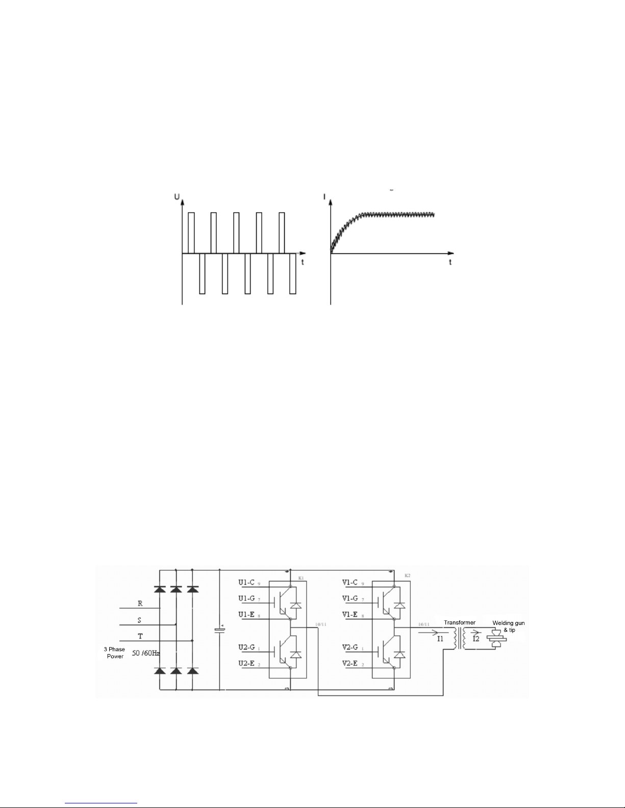
The output for the middle frequency inverter is direct-current waveform. This results
in more straightforward control of the welding process, shorter welding time, and
more consistent welding quality. The welding controller power source frequency is 1
kHz, as opposed to the traditional 50 Hz power source, which allows for much more
precise heat control.
Inverter output voltage Corresponding Output welding current
Compared to traditional welding controllers, the middle frequency inverter has the
following advantages:
1. The welding current is DC, therefore the welding current is less influenced by
inductance from the secondary circuit.
2. Smaller welding transformer is required
3. Increased electrode life cycle
4. Thinner materials, three-layer materials, and materials such as aluminum and
zinc-plated metal can be welded with good results
5. Precision welding
6. Minimized explosions
7. Spot weld quality improves greatly due to better electric current control
II. Variable Frequency Controller
Page 1
1
Page 5
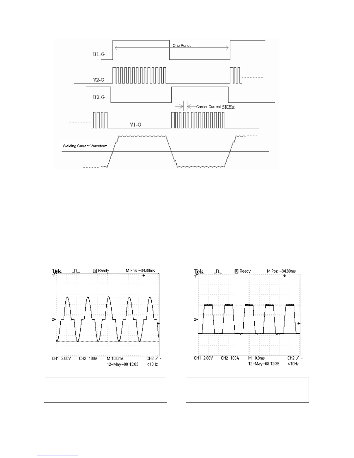
After the three-phase AC 50/60Hz input goes through the rectifier, the filter turns the
smooth direct current, makes the switch component by IGBT/K1 to have the
alternate voltage output, realizes the hypothesis welding current output through the
adjustment high frequency (5KHz) work's IGBT/K2 clear pulse width.
1. Variable Frequency vs. Normal Frequency Controller Comparison
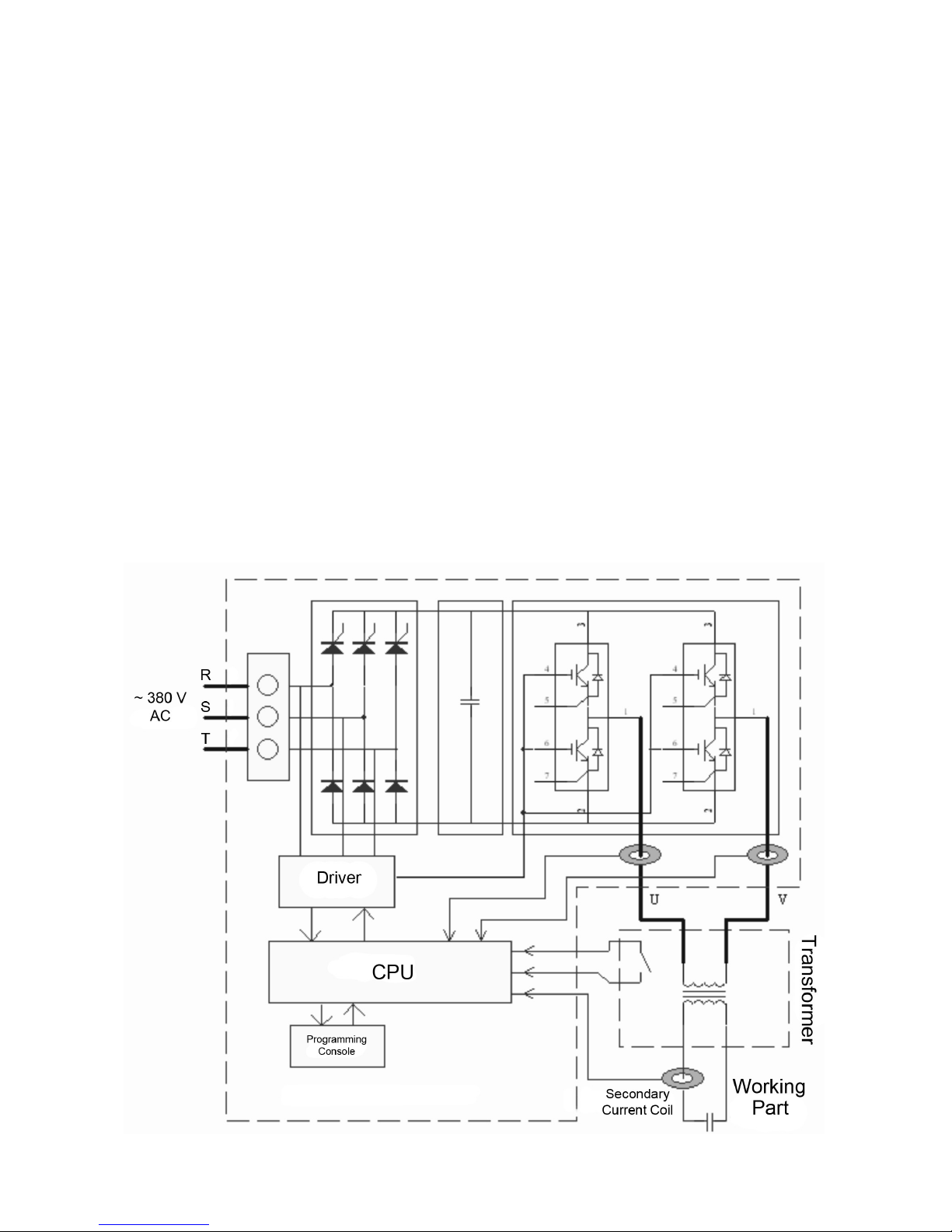
Compared to common power welding controller shows the variable frequency
welding controller to have higher heating efficiency and lower peak current.
Page 2
2
Variable Frequency at 50Hz, secondary
current: 10.0KA, the transformer ratio: 80
Common power frequency at 50HZ,
secondary current: 10.0KA, the
transformer ratio: 80
Page 6
Compared to common power frequency controller, the variable frequency conversion
controller has the following advantages:
1. The three-phase AC mains input, more balanced power usage; higher power
factor
2. To the same welding work piece, the weld period reduces, saves electricity;
Welding stability region enlarges; The electrode life grows
3. Can weld with good results: aluminum, the galvanized sheet, high-tensile
steel, stainless steel, magnesium alloy, carbon steel, titanium, etc.
4. Can weld with good results: three-layer materials, and thin materials
5. Less sparking
6. Higher weld spot quality due to faster electric current control response
III. Welding Controller Configuration
The entire control system consists of: the welding controller, the welding
transformer, and the welding gun. The welding controller consists of: the power
supply, the rectifier, the capacitor, IGBT, and the CPU.
Page 3
3
Page 7

! 1. Main features:
1. Welding frequency: programmable between 25.0Hz ~400.0Hz
2. Up to 64 sets of programmable welding condition
3. Three section of thermal processes: Preheating, welding, tempering;
Each process has its own stepper
4. The programmable pressure control, able to define up to 10 pressure
sections
5. Programmable output: 3 ways of outputs with PLC, robot, etc.
6. Spot weld count function.
! 2. Technical parameters:
1. Input voltage: Three-phase 380V, 50Hz/60Hz, power variation +10%, 20%
2. Output voltage: Single-phase PWM outputs 500V
3. Output current: Peak current 400A
4. Cooling water: Minimum capacity 6L/min, temperature ≤ 30℃
5. Working condition temperature: 0~50℃
6. Air valve voltage: DC24V
IV.Operation Description
The controller has two welding modes: Spot welding and seam welding.
1. Spot Welding
The welding start signal (X10 -10) will start the solenoid valve, but the
controller will not begin the welding process until the welding enable (X10 - 7) is
switched on. The Weld/No Weld (X10 - 5) is closed, the welding heat will start,
otherwise the welding process will start but with not current. The start signal will
begin the welding process. This welding process includes initial squeeze, squeeze,
heat 1, cool 1, up slope, heat 2, cool 2, down slope, heat 3, cool 3, hold time, off
time. After the welding has finished, the controller sends out a welding end signal.
Each welding schedule has its own “prohibit start” parameter. This parameter permits
or forbids the welding schedule to sequence, When this parameter is ON it will not
allow welding; When OFF, the welding schedule starts.
The spot welding welding sequence time chart is shown below:
Page 4
4
Page 8

2. Repeated Spot Welding
In repeated spot welding mode, when the controller sends the start signal,
then the output solenoid valve will stay on with the welding clamp closed until the
start signal is switched off. When the start signal is switched off, the controller will
wait until the next start signal to continue to next process.
The repeated spot welding sequence time chart is shown below:
3. Seam Welding Mode
In order to enter Seam Welding Mode, the DIP switch 5 should be switched to
the on position. In this mode, when the start signal is switched on, the solenoid valve
will switch on and the first heat cycle and cool cycle will start. Then heat 2 and cool 2
Page 5
5
Page 9

will repeat until the start signal is switched off if spare 2 and spare 3 (X11 - 2,3) are
maintained off. But if spare 2 is on, then heat 2 becomes seam 2. If spare 3 (X11 - 2)
is switched on, then heat 2 becomes seam 3. If both are switched on (X11 - 2,3) then
heat 2 becomes seam 4. When the start signal is dropped, then the solenoid valve
will shut off.
The seam welding sequence time chart is shown below:
V. Stepper Function
In order to compensate for the current reduction produced by electrode wear
and tear, our welding control has a function that allows the current to increase in
steps. The user can step-wise increase the electric current a total 10 times according
to the current situation. This function involves a couple parameters: increasing the
electric current, increasing the gap between welds, increasing the electric current in
steps, increasing the weld count in steps, and notifying the point of step increase.
Page 6
6
Page 10

1. Increasing the electric current: The process of increasing the current
correlates to the electric current settings for the total capacity of the electric
current. Range 0-999.9%.
2. Increasing the gap between welds: Electric Current steadily increases the
weld count for the welding process. Range 0-999.9%.
3. Increasing the electric current in steps: Each increase of each section
correlates to the total electric current capacity percentage increase (current
increase). For example, one step increases the electric current quantity of
Section 1 by 1%, the final result of this increase in Section 1 is (1 + electric
current increase X 1%) X the value of the welding current setting.
4. Increasing the weld count in steps: Each step increases the spot number of
the section each step occupies to increase the spot number percentage
during its process, for example 1% C, each step increases the spot weld
number of Section 1 to occupy the percentage of the total spot count.
Therefore the step increases in the spot number of section 1 = the interval X
1% C.
5. Notifying the point of step increase: Before each step increase process
completes the Nth spot it will inform the user that the process is about to
finish.
6. Electrode early warning: During the last sharpening process, when it is about
to terminate, N spot before the end it will raise a warning beforehand, namely
the electrode warning spot, its value range 0-9999.
7. Number of times electrode sharpened: The user can set the total number of
times to sharpen the electrode according to each actual situation.
Page 7
7
Page 11

VI. Electric Current Monitoring
The electric current monitoring function is used to inspect the actual current
flow during the welding process, and will feed back the value of the electric current
together with the defined reference value and the difference between the two values,
and will compare this value to the limiting value for the purposes of continuing the
welding.
When the measured current value exceeds the allowed error range, the
controller will generate a report or set off a warning. If the measured current value is
below the allowed error range, it will start a counter, and by a comparing, and if it is
permitted to repair, then the controller will repair weld once over the weld spot.
Then regarding to each weld, each pulse can be set to monitor the electric
current. When the measured value exceeds the correct current value, a report can
be produced or a warning signal can be produced. Regarding preheating, welding,
tempering with the three-step welding process, defining the reference value to
distinguish the electric current, the upper boundary, it is allowed to deficient limit
value and report the deficient limit value. As the image shows:
Page 8
8
Page 12

1. Preheating (welding or tempering) reference value: You can set up a
reference to the actual electric current value, electric current exceed limit,
based on parameters set by the limits to the reference value as the standard.
2. I * Exceeding reference value: With regards to the current I* (* =1,2 or 3,
corresponding to the three process of preheating, welding and tempering
separately), it corresponds to the upper limit of its electric current’s reference
value, and when the actual electric current oversteps this limit, the welding
control system can an alarm, it is possible for this welding control system to
only raise an alarm and not discontinue the welding process, but is also
possible to break off the welding process, this function makes it possible to
bypass the motherboard S6 code switch settings.
3. I * reporting failed value: the measurement value of electric current values
correlating to the reference value has a lower limit of error, namely the
alarming failed value, and when the electric current measurement value
oversteps the limits, it will post the report, and it is now possible to stop
welding, and possible to not stop welding, and again start it again.
4. I * allowing a limit deficient value: regarding the electric current reference
value is possible to set one permitted deficient limit value, it is also a
percentage, between the permitted limit deficient value and the reported limit
deficient value, it is also possible to draw a setting: even deficient limit weld
count, namely it is possible to allow a continuous n-number spots located
between the allowed limit deficient and alarming limit deficient, if in excess of
n points after the alarm, and complete the welding process.
5. Linked limit deficient weld counts: when the actual electric current value falls
between the electric current alarm limit deficient and electric current allowed
limit deficient values, in that way to permit another welding one more time, if
the next weld still falls within in this range, further doesn’t overstep “even limit
deficient weld count” range, in that way it also can again weld one more time,
Page 9
9
Page 13
until it reaches the linked limit deficient weld count setting, if the next spot still
is limit deficient, the standard weld control machine will report this.
VII. Programmable Welding Pressure
A pressure step curve can be at most set up 10 step increase sections; each
step increase of each section corresponds to a pressure and a time. The user can
set the proportions of the valve’s output according to the actual application
circumstances.
1. Pressure-based values: to set up the welding control machine treat the
machine in standby mode of the pressure value, it is in proportion to the
percent of maximum output pressure
2. Actual output pressure = pressure based value * maximum output
pressure proportional value
3. Pressure section 1 pressure: Pressure step increase section 1 pressure
relative to the maximum pressure percentage, in the same logic, every
pressure step increase section corresponds to one pressure value. It is the
scale for the maximum output pressure valve as a standard.
4. Pressure section 1 time: the pressure continuance time of the pressure
step increase section 1. Similarly, every pressure step increase
corresponds to a time period value.
VIII. Programming Console Manual
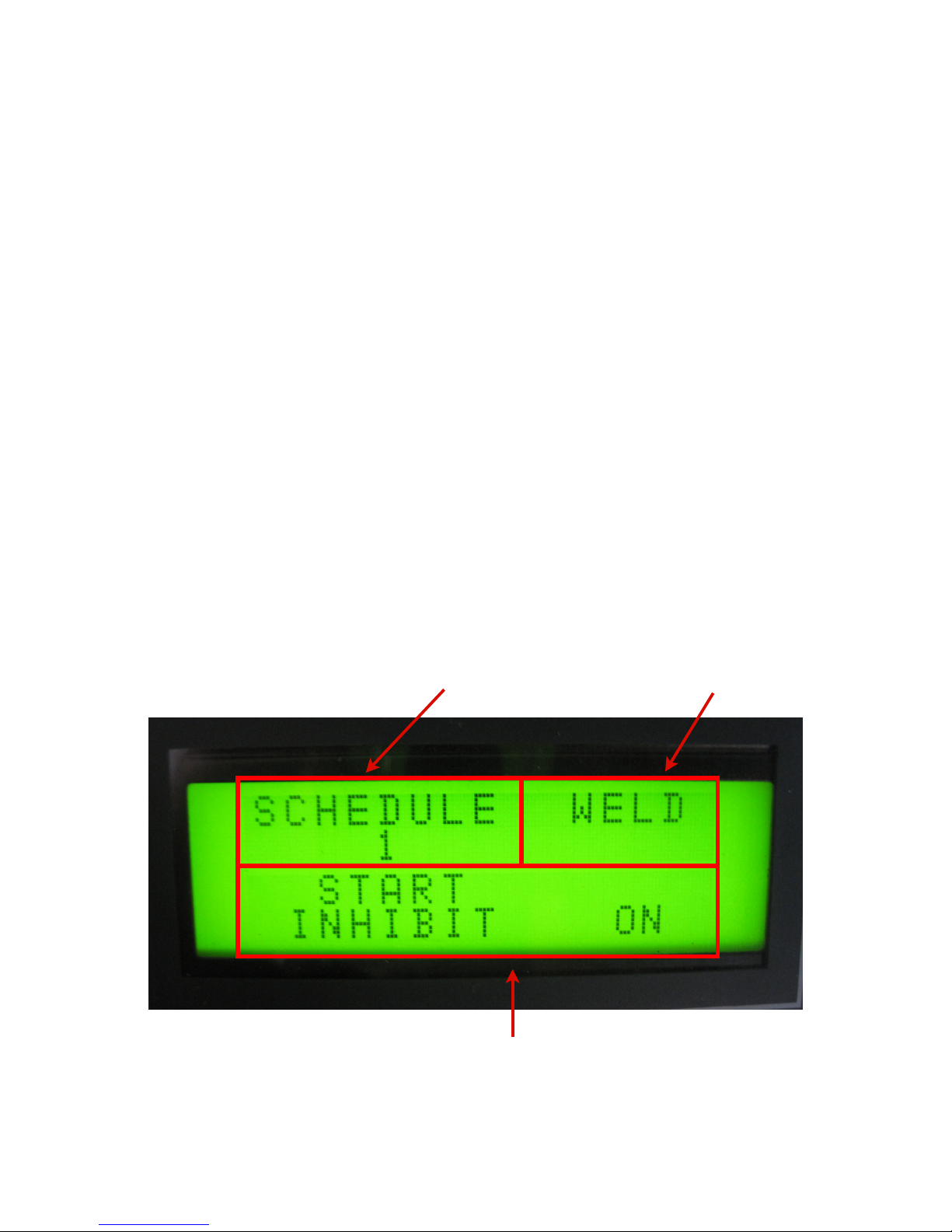
1. Programming Console Screen
Page 10
10
Mode
Schedule
#
Parameter
Page 14
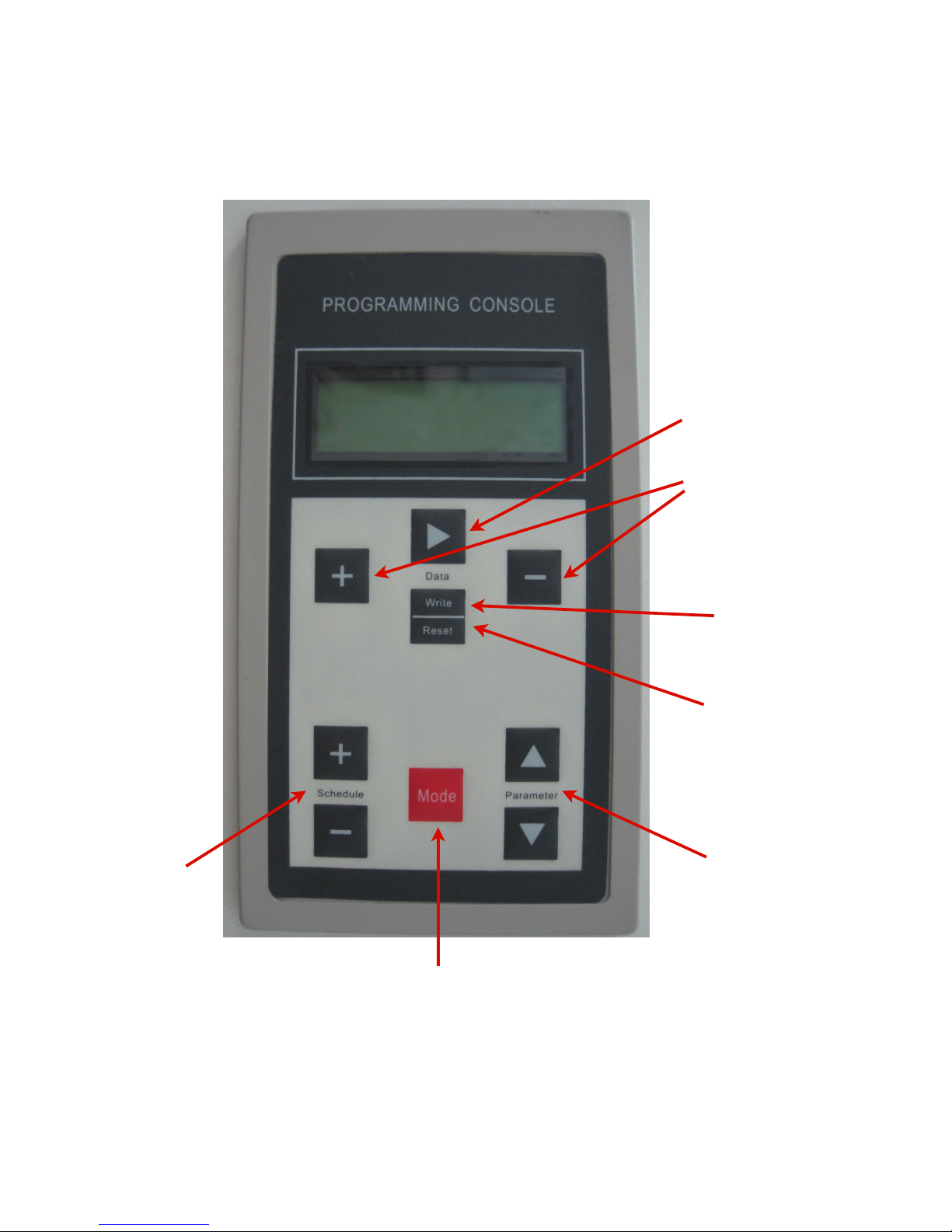
2. Programming Console
Page 11
11
Parameter
Selection
Mode Selection: (See Below)
Schedule
Selection: Up to
64 different preprogrammed
schedules.
(Default:
Schedule 1)
Modify Parameter:
The [] key selects
the current parameter
to modify by using the
[ + ] and [ - ] keys.
(Only in Prog. mode)
Write Parameter:
Saves changes to
parameter settings
Reset Parameter:
Resets error
messages.
Page 15

3. Modes
The controller operates under four modes accessible by the red mode
selection button on the Programming Console:
1. Welding mode (WELD): Normal welding mode
2. Test mode (TEST): Normal welding motion without welding current
3. Programming mode (PROG): Parameter programming mode (see programming
parameter list below)
4. Monitor mode (MONI): Monitor parameters are displayed (see monitor parameter
list below)
4. “Programming”, “Test”, and “Weld” Mode Parameter List
Start Inhibit
On/Off
On / Inhibit Welding
Off / Permit Welding
Pulse Start
On/Off
On / Pulse Start
Off / Normal Start
Initial Squeeze
0-9999 ms
Squeeze
0-9999 ms
(1,2,3) Heat Mode
KSR/KUR/PHA
KSR / Constant Current Control Mode
KUR / Constant Voltage Control Mode
PHA / Phase Angle Control Mode
(1,2,3) Weld Time
0-9999 Hz
(1,2,3) Heat
0-99.99 Ka (% if PHA)
(1,2,3) Cool Time
0-9999 ms
Up/Down Control
On/Off
On / Preheat function will ramp up current and temper
function will ramp down current
Off / Preheat and temper function is disabled
UpSlope Time
0-9999 Hz
Only when
“Up/Down
Control” is on
UpSlope Heat
0-99.99 Ka (% if PHA)
DownSlope Time
0-9999 Hz
DownSlope Heat
0-99.99 Ka (% if PHA)
Heat2 Pulse
1-99
Hold Time
0-9999 ms
Off Time
0-9999 ms
Trf. Turns Ratio
1.0 - 199.9
Page 12
12
Page 16

Repeat/Single
On/Off
On / Repeated Welding
Off / Single Spot Welding
Hold End Time
40-1000 ms
Measure Delay
0-99 ms
Trail Current
On/Off
On / Trail current monitor function is on
Off / Trail current monitor function is off
Reweld On/Off
On/Off
On / Automatic re-weld if welding current is not met
Off / Re-weld is off
Reweld Number
1-99
Only When
“Reweld On/
Off” is on
(1,2,3) Heat Monitor
On/Off
On / Preheat monitoring is on
Off / Preheat monitoring is off
(1,2,3) Heat
Reference
0-99.99 Ka
Preheat monitor reference value
Only when
“Heat Monitor”
is on
(1,2,3) Heat
Limit +
0-100.0%
(1,2,3) Heat
P.Limit -
0-100.0%
(1,2,3) Heat A.
Limit -
0-100.0%
C.C. Lower Count
1-99
Base Pressure
0-100.0%
Pressure Profile
On/Off
On / Enable programmable pressure function
Off / Disable programmable pressure function
P. Step(1-10)
Time
0-9999 ms
Only When
“Pressure
Profile” is on
P. Step(1-10)
Pressure
0-100.0%
Heat Step On/Off
On/Off
Page 13
13
Page 17

Heat Step
(1-10).%I
0-100.0%
Stepper Current Increase
Only When
“Heat Step
On/Off” is on
Heat Step
(1-10).%C
0-100.0%
Heat Step Up
0-999.9%
Pressure Step
Up
0-999.9%
Step End Notice
Step Up Count
El. Repair On/Off
On/Off
El. Repair Count
0-9999
Only When
“El. Repair On/
Off” is on
El. Repair Notice
0-9999
Freely P. Output On/Off
On/Off
On / Enable programmable output function
Off / Disable programmable output function
Off (1,2,3) Time
0-9999 ms
Only When
“Freely P.
Output On/Off”
is on
On (1,2,3) Time
0-9999 ms
5. “Monitor” Mode Parameters List
Weld Count
max: 9999
Step Pointer
%
Step Count
El. Repair Count
Voltage of Capacitor
V
Heat(1,2,3) C. Voltage
V
Heat(1,2,3) S. Current
KA
Heat(1,2,3) Time
ms
Heat(1,2,3) Phase
IX. DIP Switch Configuration
1. S1, S4, S5, S6, S7, S8
On
OffS1Secondary sensor is installed
Secondary sensor is not installed
S4
Allow monitoring of system
parameters
Normal parameter monitoring
S5
Seam welding
Spot welding
S6
Warning messages will interrupt
welding
Warning messages will not interrupt
welding
Page 14
14
Page 18

S7
Primary side current feedback
If secondary sensor is installed then
secondary sensor current feedback is
operational. If secondary sensor is not
installed then controller defaults to
primary side current feedback.
S8
Restricted to equipment manufacturer
2. Programmable Pressure Control Combinations (S2, S3)
S2S30-10V
Off
Off
0-10V
On
Off
4-20 mA
OffOn0-20 mA
On
On
X. Error Messages and Troubleshooting
1. Air valve supply voltage is low: Check air valve work power source (X12 binding
clamp 24V2).
2. Inverter drive error: Check IGBT current and corresponding drive circuit.
3. Heat Sink Overheat: Check heat sink water flow; Check if the temperature relay
is closed on motherboard.
4. Primary side electric current unnormal: Check if controller output current is too
large; Check if the transformer has short-circuited; Check primary current relay
on motherboard.
5. Capacitor voltage is unnormal: Check power supply network.
6. +5 power source too high, +15 power source too low, -15 power source too low:
Check motherboard power supply
7. Transformer temperature is too high: Check transformer water supply; Check
transformer temperature relay on motherboard.
8. 24V power source unnormal: Check motherboard power supply.
9. Secondary current sensor error: Check if secondary current transformer has
short-circuited or is damaged; Check transformer connections
10.Welding current is too large: Welding current exceeds programmed welding
current range; Check welding current parameter settings; Check welding system.
11.Welding current is too small: Welding current exceeds programmed welding
current range; Check welding current parameter settings; Check welding system.
12.Continuous current is low: Check if welding current has exceeded parameter
settings; Check welding current parameter settings; Check welding system;
Check secondary circuit
13.Requesting electrode replacement: Replace electrode.
14.Requesting electrode redress: Redress electrode.
15.Programming parameters are unnormal: Check if welding start conditions exceed
parameter range settings
16.System count unnormal: Motherboard is damaged
17.Water pressure unnormal, air pressure unnormal: Check water and air supply;
Check water and air pressure relays
18.Starting is prohibited: “Prohibit Start” parameter is on.
Page 15
15
Page 19

XI. Fig.1 Motherboard Terminal Wiring Diagram
Page 16
16
Page 20
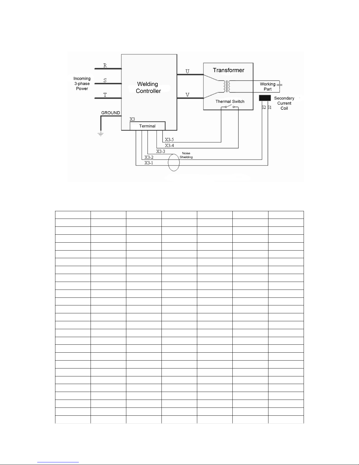
XII. Fig. 2 System Wiring Diagram
XIII. Fig. 3 Schedule Selection
1 (X11 - 9)
2 (X11 - 8)
4 (X11 - 7)
8 (X11 - 6)
16 (X11 - 5)
32 (X11 - 4)12x3x4
x
x5x6x
x7x
x8xxx9x10xx11
xx12
xxx13xx14
xxx15xxx16xxxx17x18
xx19
xx20
xxx21xx22
xxx23xxx24xxx
x
25
x
x
26
xxx
Page 17
17
Schedule #
Page 21

27
xxx28xxxx29
xxx30xxxx31
xxxx32
xxxxx33x34xx35
xx36
xxx37xx38
xxx39xxx40xxxx41
xx42
xxx43xxx44xxxx45
xxx46xxxx47
xxxx48
xxxxx49xx50
xxx51xxx52xxxx53
xxx54xxxx55
xxxx56
xxxxx57xxx58xxxx59
xxxx60
xxxxx61xxxx62
xxxxx63xxxxx64xxxxx
x
Page 18
18
Schedule #
 Loading...