

Page 1
158 --017 53
» Easy to Install
» External Manua l Override
Switch
» Match Water Heater Off
Times to Peak Energy
Periods of Utility to
Reduce Demand
» External Load Indicator
» 25 A (6250 W) Resistive,
208-250 VAC, 60 HZ
» 1500 W Tungsten,
208-250 VAC, 60 HZ
» 2 HP, 20 FLA, 80 LRA @
208-250 VAC, 60 HZ
• Disconnect p ower at the circuit breake r(s) or disconnect swi tch(es)
before installing or servicing.
• Installation a nd/or wiring must be in ac cordance with nation al and
local electrical code requirements.
• Use #14 - #10 AWG wires, rated at least 9 0° C - COPPER conductors
ON LY.
• Do not remove insul ator.
• KEEP DOOR CLOSED AT ALL TIM ES when not servicing .
• Turning this switch off w ill still leave the possib ility for hazardo us
voltage at the wate r heater.
• More than one circ uit breaker or discon nect switch may be requir ed
to de-energ ize the equipment befor e servicing.
WARNING
Risk of Fire or Electric Shock
NOTICE
• Rotate timer dial clockwise only.
• Do not move the clock ha nds on the timer. Moving the clo ck hands
can damage the t imer.
WH21 Electric Water Heater
Time Switch
Step 6
Using pliers, g rip folded down hasp on side of c ase and rotate it
upward as shown. Al so, install exter nal push butto n in the inside of
cover by insert ing plastic button into the re ctangular and round hol es
as shown then pre ssing round tabs into round h ole in cover. Close
cover to make sure the ho les in cover line up. Adjust, if req uired.
Step 8
Check wiring, ti me setting (a.m./p.m.) and progr am. If hard wired, also
close Water Heater Termi nal Box. Restore electric s ervice (the reverse
of Step 2).
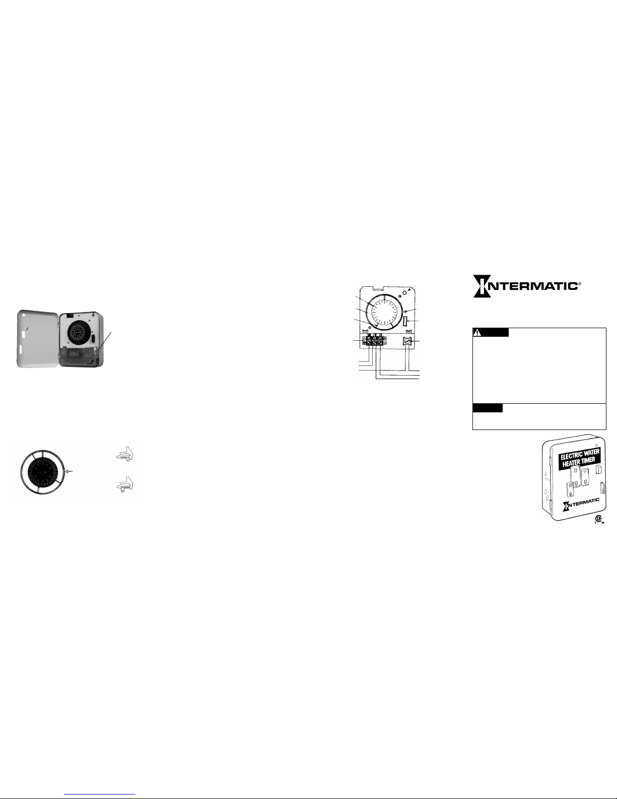
Operating Instructions
This Time Switch w ill repeat a preset sched ule daily except when the
EXTERNAL MANUAL PUSH BUTTON is used. This manua l button
permits the us er to turn the water heater ON and OFF ahead of the
schedule. The T ime Switch will resume the preset prog ram by the next
scheduled ON or OFF operation. T he diagram on the right shows th e
mechanism an d wiring of this Time Switch. The TIME MARK is used to
line up the corre ct time of day on the TIME DIAL. The ON and OFF
TRIPPERS turn the wate r heater ON and OFF at the times indicate d
by their respec tive position on the TIME DIAL.
To Set Program
1. Gr asp time dial rmly. PULL and remove time dial completely from
tim er.
2. Remove all ON trip pers (silver) and OFF trippe rs (brass). Use
pencil or pape r clip if necessary.
3. Insert OFF tripper s (brass) in slots for desir ed OFF times, but NOT
CLOSER than 2 hou rs apart.
4. Insert ON trippers (s ilver) in slots for desired ON tim es, but NOT
CLOSER than 2 hou rs apart. ON and OFF tripper s may be spaced
1/2 hour apart fro m each other.
5. Replace tim e dial. PUSH IN FIRMLY. If any trip pers a re near the
time mark, rota te time dial to avoid interferen ce with mechanism
inside.
6. Turn time dial CLOCKWISE one or m ore revolu tions un til correct
time-of-day is opposite time mark.
TO STOP AUTOMATIC OPERATION: (But with out stopping timer)
PULL outward on time d ial until it clicks.
TO RESUME AUTOM ATIC OPERATION: PUSH inward on t ime dial.
AFTER POWE R FAILURE: (or if water heater was d isconnected at
main panel) tim e dial must be reset to corre ct time-of-day.
DISCONNE CT POWER AT THE CIRCUIT BRE AKER(S) OR
DISCONNECT SWITCH(ES) BEFORE INSTALLING OR SERVICING.
TURNING TH IS SWITCH OFF WILL STILL L EAVE THE POSSIBILI TY
FOR HAZA RDOUS VOLTAGE AT THE WATER HEATER .
Step 7
Set the daily pro gram - see operating inst ruc tions on page 7. Each
individual hou sehold should determin e a schedule to suit their own
needs. Adjus tments should be made for fam ily size, hot water needs,
appliances , etc. In areas where time -of-day rates are in effect, co nsult
the electric u tility company to nd when the l owest rates apply. Then
set the time switch to op erate the water heater when the e lectric rates
are lowest and adju st the schedule accordi ngly.
In setting the sc hedule, consider the fac ts that the temperature and
quantity of hot wa ter will decline during the OFF p eriods depending on
amount used an d Iength of OFF time. A typica l schedule could be ON
at 6 a.m., OFF at 8 a.m. for mo rning use, and ON again at 5 p.m. an d
OFF again at 10 p.m.
External
Push Button
Hasp
Adjust if required.
To open the door,
push the hasp
gently to the lef t
while pulling o n the
door of the unit .
ON Tripper
OFF Tripper
Time Mark
ON Tripper
OFF Tripper
OFF Tripper
(Brass)
ON Tripper
(Silver)
View of Dia l at Midnight
Typical Program
ON TRIPPER
(SILVER)
OFF TRIPPER
(BRASS)
TIME DIAL
TERMINAL
BLOCK
IND ICATOR
LAMP
TIME MARK
MANUAL
CONTROL
GROUNDING
SCREW
GRD
LINE 1
LINE 2
GRD
250V
FROM
FUSE
BOX
{
TO
WATER
HEAT ER
}
Page 6 Page 7
Page 8
To purchase extra trippers: order part no. 156EB1945A for a set of
two (2) ON and two (2) OFF tri ppers.
Page 2

Step 1
A. Checking:
» Make sure the Time Sw itch and the water heater VOLTAGES are the
same.
» Make sure the water he ater rating in WATTS is not over the
maximum cap acity of this Time Switch.
» Make sure the water he ater is wired with COPPER wire.
Do not conne ct ALUMINUM wire s to the terminal s of this Time
Switch. Consult an el ectri cian if th e existing wires are ALUMINU M.
Disconnec t power at the circuit breaker(s) o r disconnect switch(es)
before installing or servicing.
B. Planning and Measuring:
Here is how the water he ater is wired now, BEFORE the insta llation of
this Time Switch:
Here is the modi ed wiring, AFTER the Time Switch i s installed:
» Plan a convenient l ocation for the Time Switch, pr eferably eye level
(also out of reach of s mall chil dren), and s uch that existing cable
(Fig. 2, or Fig. 3 ltem #3) may b e utilized.
» Measure the dis tance (Item #5) from the Time Sw itch to Water
Heater Terminal Box (Ite m #4). Also measure dis tance (Item #3) f rom
Time Switch to Junc tion Box if existing cable (Fig. 2, lte m #3) is too
short. Allow f or slack and 6 inches of hook-up le ads at each end to
facili tate wiring connections.
C. Materials Needed
If the wate r heater is HARD WIR ED: (See Figure 2 )
• Ob tain a piece of cable, the SAM E TYPE (that is, metallic or
plastic) and SAM E GAUGE with COP PER con ductors to make ltem
#5 connection (a nd Item #3, if needed) as show n. See also gauge
selec tion char t below.
• Ob tain 2 cable connectors ( Item #6) to t the cable above.
If the wate r heater is CORD and PLU G connected: (S ee Figure 3)
• Ob tain the SAME TYPE and GAUG E cordset with plug as pres ently
used on (Item #3) an d 2 strain relief grommets ( Item #7) to t THIS
cordset.
D. Tools Needed
Hammer, 1/4" wide screwdriver, drill, plie rs, wire cutter and strip per.
Size of Fuse
or Circuit
Breaker
Minimum
Gauge of
Copper Wire
125 or 250
VAC
Water Heater Capacity
125 VAC 250 VAC
A #AWG A W W
15 14 15 1875 3750
20 12 20 2500 5000
25 10 25 3125 6250
Step 3
Mount timer cas e on wall as outlined in step 1B. Mark top m ounting
hole. Drill hole i n mounting surface and dr ive screw into hole. Hang
timer on screw. From the in side put screws into two botto m mounting
holes. Use anch ors if necessary.
Step 5
Move insulator out of t he way and connect the wires co ming from the
service box a nd from the water heater to the termi nals of the time
switch mechanism. For wiring connections re garding a specic model,
refer to diagram in side the time switch door. Attach wi re ends to time
switch terminal s as shown in wiring diagram. In sert only the strippe d
copper ends of w ires UNDER the pres sure plates of te rminal screws as
shown. Using 3/16" or large r screwdriver, TIGHTEN TERMINA L
SCREWS FIRMLY (torque 20- 30 Lb In.). Note: Time Switch may not
operate if termi nal screws are loose. Now repl ace front insulator cover.
See illustration below.
1
2
3
4
Figure 1
Water
Heater
Water
Heater
Water
Heater
6
Time
Switch
Time
Switch
Figure 3: Cord and Plug ConnectedFigure 2: Hard Wired
2
3
5
4
4
7
2
5
3
Service Box - The water heater sho uld have its own (separate)
fuse or circuit b reaker in the electrical p anel.
Junction Box - The wiring may or may not i nclude this
convenience box. I t may contain a disconnec t switch and/or
receptacle if w ater heater is cord connec ted.
Water Heater Connection - This is a rigid or exible (met allic or
plastic) cable c ontaining 2, 3 or 4 insulated wir es of different
colors.
Water Heater Terminal Box - This is part of the wate r heater
where the power sup ply wires are connected.
Step 4
If the wate r heater is HARD WIR ED:
Remove the cover of water h eater terminal box (Fig. 1, Item #4). IS
ELECTRICITY TURNED OFF? NOTE COLORS OF WIRES.
Disconnec t wires and cable connecto r. Remove the most convenient
knockout of the tim e switch case and attach ca ble (Fig. 2, Item #3) and
cable connec tor to case. If a 3/4 inch knockout is nee ded, remove the
1/2 inch knockout rs t, then the 3/4 knockout. Pre pare anothe r cable
(Fig. 2, ltem #5) by strip ping the ends of wires 1/2 inch. Using c able
connec tor (Fig. 2, ltem #6), at tach this cable to water heat er terminal
box and then the wire s to water heater terminals.
NOTE: If there were gre en and/or white wires in the ter minal box
before, conne ct the same colors to these s ame terminals. TIGHTEN
TERMINAL SCRE WS FIRMLY (torque 20-30 Lb In.). Remove anoth er
knockout of the tim e switch case and connect th e other end of this
cable to the case, u sing the other cable conne ctor, Item #6.
Mounting Holes
Knockouts
Hard Wired Cord and Pl ug Connected
Cable
Connectors
New Cordse t with
Plug (Item # 5)
Water Heate r Cord
without P lug (Item #3)
Strain
Relief
Grommet
If the wate r heater is CORD and PLU G connected:
Remove plug at end of wa ter heater cord (Fig. 1. Item #3). Split co rd
about six inche s and strip wire ends 1/2 inch. Rem ove the most
convenient kno ckout of the time switch case and at tach cable (Fig. 2,
Item #3) and cable c onnector to case. If a 3/4 inch knoc kout is needed,
remove the 1/2 inch knocko ut rst, then the 3/4 knockout. Ins tall strain
re lie f grommet (Fig.3, Item #7) and at tach cord to case as shown. Nex t,
install strai n relief grommet to the other co rdset (Fig. 3, Item #5) and
attach cord set to case as shown be low.
Step 2
Disconnec t power at the circuit breaker(s) o r disconnect switch(es)
before install ing or servicing. Pull plu g, if cord connected; remove fu se
or open circuit b reaker if hard wired. More th an one circuit breaker or
disconnect sw itch may be required to de-e nergize the equipment
before servicing.
1
2
3
4
Page 2 Page 3
Page 4
Page 5
Electrical
Service
Box
To
Water Heater
From
Service Box
Pressure Plate
Terminal Screw
Make sure wi re
insulation clears
pressure plate.
Grounding wire,
if required.
 Loading...