

Page 1
PE SERIES POOL/SPA
EQUIPMENT CONTROLS
INSTALLATION
OPERATION &
SERVICE MANUAL
MMooddeell:: PPEE4400000000 SSeerriiees
s
CCOONNTTRROOLL PPAANNEELL FFOORR IINNDDOOOORR//OOUUTTDDOOOORR UUSSE
E
Suitable for Pool Equipment Control and for Direct Conduit Connection to a Wet-Niche or NoNiche Luminaire
EELLEECCTTRRIICCAALL RRAATTIINNGGSS:: SSeeee iinnssiiddee eenncclloossuurree ddoooor
r
AALLLL DDEEVVIICCEESS IINN TTHHIISS CCOONNTTRROOLL MMUUSSTT BBEE SSUUPPPPLLIIEEDD BBYY BBRRAANNCCHH CCIIRRCCUUIITT PPRROOTTEECCTTOORRSS LLOOCCAATTEEDD WWIITTHHIINN TTHHIISS EENNCCLLOOSSUURREE..
PP11335533MMEE DDiiggiittaall TTiimmee CClloocckk:: SSeeee rraattiinngg iinnssiiddee eenncclloossuurree ddoooorr ((CClloocckk nnoott iinncclluuddeedd wwiitthh aallll mmooddeellss)
)
The short circuit current rating of this panel board is 10,000 symmetrical amperes.
Man
y of today’s energy efficient pools and spas
utilize the advantages of a single electrical
panel, containing all the necessary controls for
the safe, efficient and automatic oper
ation of
the pool/spa equipment. In addition, this panel
can also be used to control any outdoor
equipment, sign or pump within its rated
capacity.
As an option this all-weather enclosure
contains the hea
vy-duty
, industr
ial g
r
ade
P1353ME Digital Time Clock. It also comes
standard with a break
er base f
or up to eight full
siz
e circuit break
ers
. In addition, it has
provisions to install wiring devices inside, as
well as a switch or GFCI receptacle on the
outside.
The P1353ME Digital Time Clock (optional) is
designed to oper
ate an
y pump
, within its r
ated
capacity. However, if protection to prevent dry
star
t is required b
y the pump man
ufacturer, it
m
ust be provided in addition to this control.
Contact pump manufacturer if not sure and/or
for more details.
1
DANGER! TO AVOID RISK OF INJURY:
...do not permit children to operate the Control Unit or use the Pool/Spa unless they are closely supervised at all times.
...test GROUND FAULT protection regularly. If it fails to reset, DO NOT USE THE POOL or SPA!
Contact a qualified service technician.
...always disconnect electricity before servicing this control or the equipment connected to it.
READ, FOLLOW AND SAVE THIS INSTRUCTION MANUAL
GENERAL INFORMATION
Because of our commitment to continuing research and improvements, Intermatic Incorporated reserves the right to make changes, without notice, in the specifications and material
contained herein and shall not be responsible for any damages, direct or consequential, caused by reliance on the material presented.
INTERMATIC INCORPORATED, SPRING GROVE, IL 60081-9698
http://www.intermatic.com
158PE13014
4
LIMITED ONE YEAR WARRANTY
If within the warranty period specified, this product fails due to a defect in material or workmanship, Intermatic Incorporated will repair or replace
it, at its sole option, free of charge. This warranty is extended to the original house hold pur
chaser only and is not transferable. this warranty does
not apply to: (a) damage to units caused by accident, dropping or abuse in handling, acts of God or any negligent use; (b) units which have been
subject to unauthorized repair
, opened, taken apart or other
wise modified; (c) units not used in accordance with instructions; (d) damages exceed
-
ing the cost of the product; (e) sealed lamps and/or lamp bulbs, LED’
s and batteries; (f) the finish on any portion of the product, such as sur
face
and/or weathering, as this is considered normal wear and tear; (g) transit damage, initial installation costs, removal costs, or reinstallation costs.
INTERMA
TIC INCORPORA
TED WILL NOT BE LIABLE FOR INCIDENT
AL OR CONSEQUENTIAL DAMAGES. SOME ST
ATES DO NOT ALLOW THE EXCLU-
SION OR LIMIT
A
TION OF INCIDENT
AL OR CONSEQUENTIAL DAMAGES, SO THE ABOVE LIMITATION OR EXCLUSION MAY NOT APPLY TO YOU. THIS
W
ARRANTY IS IN LIEU OF ALL OTHER EXPRESS OR IMPLIED W
ARRANTIES. ALL IMPLIED W
ARRANTIES, INCLUDING THE WARRANTY OF MER-
CHANT
ABILITY AND THE W
ARRANTY OF FITNESS FOR A P
ARTICULAR PURPOSE, ARE HEREBY MODIFIED TO EXIST ONLY AS CONTAINED IN THIS
LIMITED W
ARRANTY
, AND SHALL BE OF THE SAME DURA
TION AS THE WARRANTY PERIOD STATED ABOVE. SOME STATES DO NOT ALLOW LIM-
IT
A
TIONS ON THE DURA
TION OF AN IMPLIED WARRANTY, SO THE ABOVE LIMITATION MAY NOT APPLY TO YOU.
This warranty gives you specific legal rights and you may also have other rights which var
y from state to state. W
arranty ser
vice is available by
mailing postage prepaid to: Intermatic Incorporated/After Sales Ser
vice, 7777 Winn Rd., Spring Grove, IL 60081-9698/815-675-7000
http://www/intermatic.com
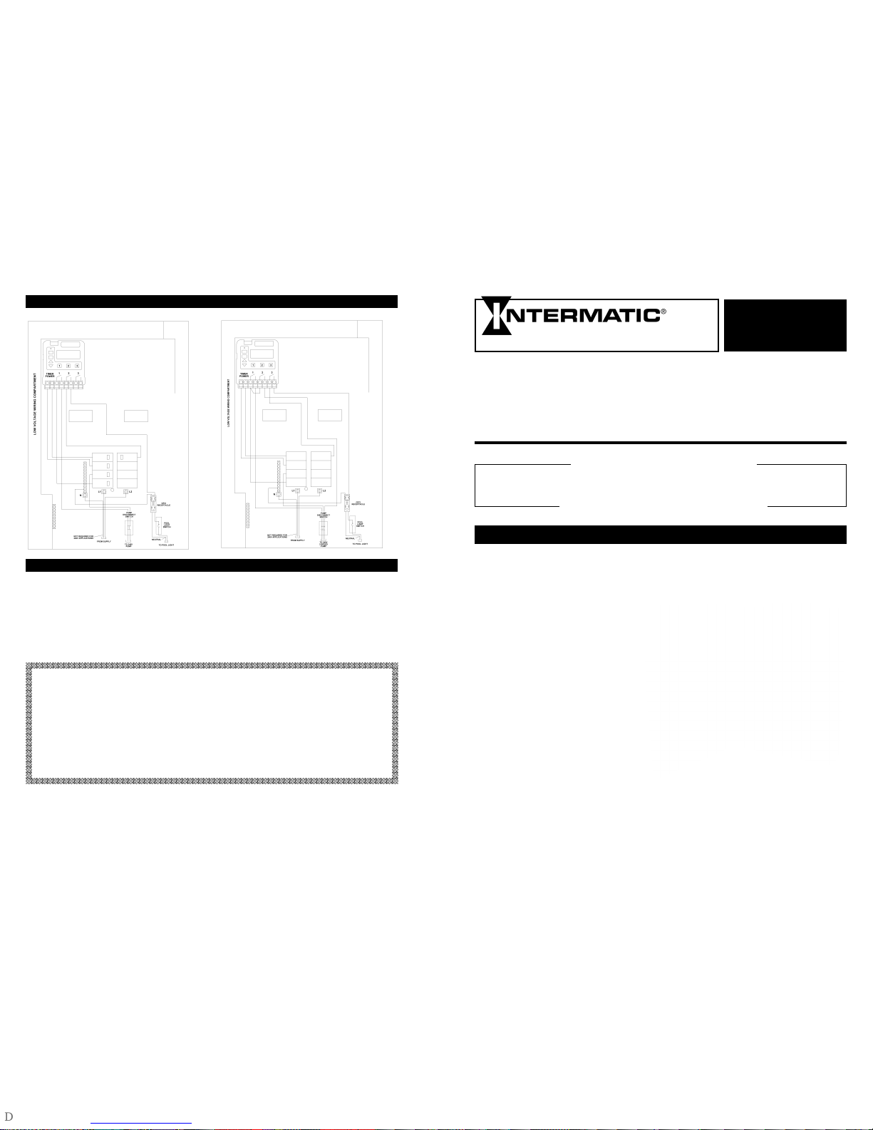
WIRING DIAGRAM
NOTES: 1. Grounding connections are not shown but must be provided. Refer to the National Electrical Code for details.
2. Diag
rams above are only two of the many variations this Panel can accommodate.
P1353ME
Operating instructions
1.Press PROG Key to cycle through menu options.
2.Press UP and DOWN arrow keys to change program settings.
3.Press ENTER key to save changes and exit programming mode.
4.Press ON/OFF keys to manually turn devices ON or OFF.
For more details, please refer to instruction manual booklet
NOTE: Refer to P1353ME instruction manual booklet for description of modes.
OPERATION
240V.FILTER PUMP, 120V. POOL LIGHTS 240V.TWO SPEED FILTER PUMP, 120V POOL LIGHTS
Page 2
INSTALLATION
ACCESSORIES
TROUBLESHOOTING
1. Remove the #10 hex head screws from the out-
side back of the enclosure and attach mounting
brackets.
2. Select the proper location for the control panel
and hang enclosure on a flat vertical surface or
other support. When mounting the enclosure, be
sure to use hardware capable of supporting its
weight.
NOTE: The Panel will accept the main feed,
through the
Ef
, 1, 1 fQinch knockouts at the
bottom of the enclosure or through the 1-
Ef
inch knoc
kouts on the back of the enclosure. A
dimple on the top of the enclosure provides a
pilot hole for o
verhead entrance into the panel.
The overhead entrance must use a listed
outdoor conduit hub and must be mounted at
the time of installation.
3. Prepare the necessary conduit runs, terminate
them at both ends and pull in the conductors as
specified by the installation layout. If this control
is used f
or direct conduit connection to a wetniche or no-niche luminaire, order one of the
following:
1/2” non-metallic - order 156PA13713A
3/4” non-metallic - order 156PA13714A
1” non-metallic - order 156PA13715A
1/2”
metallic - order 156PA14336A
4. Refer to Figure 1 below.
Note that though this figure
sho
ws a P1353ME Digital
Time Clock installed, the
P1353ME is not included on all models. See
door panel for the specific configuration and
rating of the model you are installing.
A breaker base for up to eight full size circuit
breakers is included on all models. To wire the
panel, f
ollo
w the wir
ing diag
ram located inside
the enclosure door. When wiring the P1353ME,
make sure that the connections are tight (25 lb.in.
minim
um) and
insulation c
lear
s the
pressure plate
(see illustration)..
5. If required b
y the heater man
uf
acturer
, the P1353ME
includes a connection f
or a fire-man s
witch. This
switch only works in conjunction with circuit
#1(Load #1) on the P1353ME.
Ref
er to pages 6
& 7 of the P1353ME Instr
uction Manual for
connection information, and refer to page 28 for
fireman s
witch prog
r
amming inf
or
mation. Use at
least #18 A
WG wiring with insulation rated 300
volt or higher. Some heaters may require a
special connecting har
ness
, contact heater
man
ufacturer for details. Place heater ON/OFF
switch on heater to ON position.
6. To install additional wiring devices inside the
enclosure, first remove rectangular knock-out(s)
in dead front. Next, remove hex head screws
inside back of enclosure and install stand-offs*
in place of screws. Attach wiring device to
stand-offs.
*Stand-offs are not furnished. Order 21T156A for a set
of four (4) stand-offs and mounting hardware.
7. If external bonding is required, install a bonding
lug at bottom of enclosure and bond installation
according to code requirements (Order
156T11047A for Bonding Lug Kit).
8. Testing of the installation is optional and recom-
mended only if the desired loads are securely in
place and will not be damaged by this test:
a. Turn ON power at breaker panel.
b. P1353ME display should fully illuminate and
then start to blink 12:00AM provided the
memory hold-up capacitor is discharged.
Otherwise, it will displa
y the time
.
c. Push each of the ON/OFF buttons to verify
devices cycle on and off.
In case of unsatisfactory results, turn OFF
power, check your wiring, refer to
Troubleshooting on Page 3.
9. Install front panel o
ver wiring compartment.
The control is no
w ready for programming,
see OPERA
TION section on P
age 4.
2 3
IMPORTANT SAFETY INSTRUCTIONS
W
hen installing and operating this product and other associated equipment, basic safety precautions should always be followed,
including the following:
1. Read and follow all instructions.
2. This control must be installed by a qualified electrician, according to National and Local Electrical Codes.
3. Install this control not less than 5 feet (3 meters in Canada) from inside edge of pool. USE COPPER CONDUCTORS ONLY.
4. Do not exceed the maximum ratings of individual components, wiring devices, and current carrying capacity of conductors.
5. For control grounding, bonding, installing and the wiring of underwater lights, refer to Article 680 of the National Electrical
Code or Article 68 of the Canadian Electrical Code.
6
. This control should not operate any equipment which would cause bodily injury or property damage should it be activated unexpectedly.
READ, FOLLOW AND SAVE THIS INSTRUCTION MANUAL
PRESSURE PLATE
TERMINAL SCREW
MAKE SURE INSULATION
CLEARS PRESSURE PLATE
Figure 1
SYMPTOM CAUSE(S) CORRECTIVE ACTION
1. Display will not come “ON” 1a. Jumper on back of clock is missing Set Jumper to proper location. See
when unit is powered up? or set incorrectly. Pg.7 of instruction manual.
1b. Fuse on back of clock blown open. Replace fuse with 1/8 amps fuse.
See Pg. 7 of instruction manual.
1c. Power to clock not present. Check connections to clock.
Check circuit breakers.
2. F
reeze protection circuit not 2a. Freeze Probe (P/N 178PA28A) Install Intermatic freeze probe. See
working? not installed or bad. Pg. 7 of instruction manual.
2b. Clock programming not setup. Setup freeze programming. See
Pg. 7 of instruction man
ual.
3. Unit does not turn “ON” or 3a. Internal ON/OFF Times have Setup ON/OFF programming. See
“OFF” at desired times? not been defined. Pg.’s 24-27 of instruction manual.
3b.
ON or OFF time is in o
verride mode. Cycle through programming menu.
See Pg.’s 24-27 of instruction
manual.
3c.
Cloc
k is in Freeze protection Review programming menu. See
Countdown Mode. Pg.’s 29 & 33 of instruction manual.
4. Display continues to blink ON 4a. Power to clock was interrupted long Set time of day on clock.See Pg. 23
and OFF? enough to lose time of day. of instruction manual.
4b. Clock still in programming mode. Press “ENTER KEY” or wait 1
minute for clock to time out.
5.
Fireman switch not working? 5a.Fireman switch wires not hooked up Connect fireman switch wires to
correctly from heater. clock. See Pg. 7 of instruction
manual.
5b
. Fireman switch programming not Program fireman switch settings.
defined. See Pg. 28 of instruction manual.
FLTR
PUMP
2
PUMP
1
HTR
SPA
JETS
A
IR
CLNR
LITE1
LITE2
HIGH
LOW
AUX 1
AUX 2
AUX 3
W/FAL
External Wired Remote Accessory
Part Number 133PE1484A
(not included with all models)
The New Intermatic Wired Remote Control
allows you to control the P1353ME from a
remote location. Included with the
Wired Remote Control is a label
arrangement allowing you to identify
each button specific to your pool or
spa equipment pad. The new wired
remote control comes standard with
100 foot of cable and is designed to slip fit
into any standard 1 1/2” conduit adapter.This remote
works in conjunction with the P1353ME and displays
feedback information on the present state of the pool
or spa equipment pad.
For more information refer to instructions provided with
the accessory.
Freeze Probe Accessory
Part Number 178PA28A
(not included with all models)
The New Intermatic Freeze Probe allows
you to protect your pool or spa
equipment during an
unexpected freeze condition.
T
he freeze probe comes with
a 10 foot cable and plugs into
the back of the P1353ME. The
P1353ME can be programmed
to turn on each or all-individual
loads at any desired outside temperature.
Heater Protection (Fireman) Switch is
standard with each P1353ME.
It comes standard with a Fireman Switch
connection for your pool or spa heater.
Simply connect the two wires from your
heater thermostat to the back of the
P1353ME. The fireman switch is only
associated with circuit one on the
P1353ME, therefore the filter pump should
be connected to circuit one. Program the
time desired for the cool down period and
the P1353ME will take over.
For more details, refer to P1353ME
Instruction Manual.
 Loading...