

Intermatic PanelGuard PG100 Series, PanelGuard PG60 Series, PanelGuard PG80 Series Installation Instructions And Operation Manual
Page 1
8.5”
INSTALLATION INSTRUCTIONS
and
OPERATIONS MANUAL
PanelGuard®PG60 - PG80 - PG100 Series
Electrical Panel Extension Hardwired Surge
ALARM
OPERATION
PROTECTIO
N MODES
CAUTION; HIGH V
OLT
AGE INSIDE
SEVICE BY QUALIFIED
PERSONN
EL ONL
Y
Red ALARM
light ON or
Audible Alarm
ON indicates
loss of protection. Refe
r to
the operatio
n manual for
troubleshoo
ting help.
Alarm
Neutral
L1
L2
L3
L1
L2
L3
Ground
Green lights ON indicat
e
power prese
nt and protec-
tion circuits for each mo
de
are operating propely
.
One or more
Green lights
OFF indicates loss of
power
or protection. Refer to th
e
operation manual for
troubleshoo
ting help.
INTRODUCTION
The PG60-80-100 Series is designed to be installed in very close proximity to the power bus of an electric distribution panel or electric panelboard. It can be used with most panels or panelboards in distribution
today. The PG60-80-100 Series offers peak surge amperage protection
levels of 60 kA to 100 kA per mode. It is designed to be easily mounted
above or below the panelboard. Provisions have been made with a
reversible cover plate to keep the instructions and indicators in a user
friendly position. Standard features include all mode protection, multimode LED indicators that show full protection, diminished protection and
lost protection for all phases. A form C relay for remote alarm indication,
audible trouble alarm with test and silence switch are also standard
equipment.
The system is comprised of three sections; outer housing, cover plate
and inner module. Each section is engineered to make the installer/service technician's task as easy as possible. A description of each section
and the function follows.
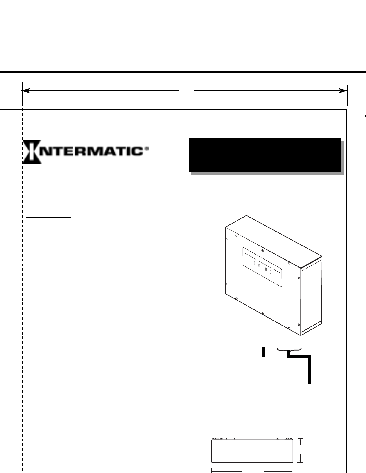
Outer Housing - Metal housing measuring 20" wide x 16" high x 6"
deep. The outer housing contains the inner housing. connection lugs for
each phase, neutral and ground, connections for the form C alarm relay
and the audible alarm test and silence switch.
A
5/8" flange on the forward side of the housing has ten (10) threaded
holes that are used to attached the cover plate. Four (4) mounting holes
are located in the back surface of the housing for mounting. It is sug
-
gested that all four (4) fasteners be used to secure the outer housing.
Cover Plate - Metal plate measuring 19 13/16" wide x 15 13/16" high.
The cover plate contains ten (10) holes located around the edges that
matched the threaded holes in the outer housing and are used to secure
the cover plate to the outer housing. The cover plate is reversible and
has an identification label on both front and reverse sides. The labels
are mirror images of each other and selection of which side to use
depends upon the placement of the outer housing. (This process will be
explained in the installation section that follows.)
Inner Module - Metal box measuring 13 3/16" wide x 9 3/4" high x 4
15/16" deep including the mounting rails that are part of the module.
The inner module is fastened to the outer housing with four (4) bolts
through the mounting rails. Module identification and wiring diagram
labels are attached to the inner module. The inner module contains all
of the surge suppression, noise filtering, fusing, monitoring and reporting
SUPPLY VOLTAGE AND CONFIGURATION
240-2S 120/240 Single Phase
208-3Y 120/208 Three Phase Wye
240-3HLD 120/240 Three Phase H. L. Delta
480-3Y 277/480 Three Phase Wye
480-3D 480 Three Phase Delta
PEAK SURGE RATING
PG60 60 kA per Mode
PG80 80 kA per Mode
PG100 100 kA per Mode
Model # PG100 - 208 - 3Y
6.0”
-
Page 2

Page 3

Page 4

2
REVISE DR
WG TO ALIGN TEXT (NO ECO)
SRB
3/2/2005 2-RM 3/2/2005 FINISH:
1 RELEASED T
O ELEC. DA
T
A
LET
. REVISION
SIGN. MODEL SUPERSEDES:
Violet - n/c
Orange - n/o
Orange - n/o
Violet - n/c
-
-
Alarm indi
-
Page 5

ALARM
OPERATION
PROTECTIO
N MODES
CAUTION; HIGH V
OLT
AGE INSIDE
SEVICE BY QUALIFIED
PERSONN
EL ONL
Y
Red ALARM
light ON or
Audible Alarm
ON indicates
loss of protection. Refe
r to
the operatio
n manual for
troubleshoo
ting help.
Alarm
Neutral
L1
L2
L3
L1
L2
L3
Ground
Green lights ON indicat
e
power prese
nt and protec-
tion circuits for each mo
de
are operating propely
.
One or more
Green lights
OFF indicates loss of
power
or protection. Refer to th
e
operation manual for
troubleshoo
ting help.
(1) What Is Covered By This Limited Warranty
Repair or Replacement of Product
Intermatic Incorporated ("Intermatic") warrants to the original purchaser only
PG60-240-3HLD, PG60-480-3Y
PG100-240-2S, PG100-208-3Y
(each a "Product") shall be free from defects in material or workmanship for a period of ten years (120 months) from date of pur
chase or 126 months from date of manufacture. If the purchaser discovers a defect in material or workmanship, the purchaser must
promptly submit a warranty claim. Upon a determination by Intermatic that the Product is defective, Intermatic shall correct any
defect in material or workmanship by, at Intermatic's option, either repairing or replacing the defective Product. Any repair, including
both parts and labor, shall be at Intermatic's expense. The foregoing remedies are the purchaser's exclusive remedies for a breach
of warranty
For purposes of this Limited Warranty, a Power Transient shall mean over-voltage resulting from momentary voltage spikes or
surges on an AC power line of magnitude that the Product, according to its specifications, is designed to stop before such spikes or
surges affect downstream equipment.
The Product must be installed in the appropriate application in complete accordance with the installation instructions. All building
wiring and other connections to the Product must conform to all applicable national, state and local electrical codes; the Product
must not be opened, modified, exposed to extreme heat or cold, submerged or subjected to abnormal use or service. All products
must be used in accordance with the instructions provided with the Product and the purchaser shall be solely responsible for select-
ing a Product model with specifications appropriate for the equipment to be protected. Intermatic shall determine, in its sole discre-
tion, whether any Product returned by a purchaser has been used in accordance with its instructions, is an appropriate model for the
purchaser's use thereof, and whether the Product is defective.
(2) What Is Not Covered By This Warranty
Intermatic does not warrant (a) defects in the Product or damage to any equipment caused by the failure to properly install the
Product; (b) damage caused by use of the Product for purposes other than those for which it was designed; (c) damage caused by
disaster such as fire, flood and wind; (d) damage caused by unauthorized attachments or modification of the Product; (e) damage to
the Product occurring during shipment; (f) damage caused by electrical disturbances exceeding published product specifications or
(g) damage to the Product caused by any other abuse or misuse by the purchaser.
(3) Disclaimer of Warranty
THE FOREGOING WARRANTIES ARE IN LIEU OF ALL OTHER EXPRESSED WARRANTIES. TO THE EXTENT ALLOWED BY
LA
W
DURA
(4)
IN NO CASE SHALL
UPON BREACH OF WARRANTY, BREACH OF CONTRACT, NEGLIGENCE, STRICT TORT, OR ANY OTHER LEGAL THEORY.
SUCH EXCLUDED DAMAGES INCLUDE, BUT ARE NOT LIMITED TO, DAMAGE TO SOFTWARE, LOSS OF DATA, LOSS OF
PROFITS, LOSS OF SA
OF CAPIT
PARTIES INCLUDING CUSTOMERS, DAMAGE TO PROPERTY AND PERSONAL INJURY. SOME STATES DO NOT ALLOW
LIMITS ON W
THIS PARAGRAPH AND IN PARAGRAPH (3) MAY NOT APPLY.
(5)
No action arising out of any claimed breach of warranty may be brought more than one year after the cause of action has occurred.
FINAL CHECKOUT PROCEDURE
1. CHECK all connections for correct location and torque.
2.
Make sure that the electrical panel and the SPD are clear of all tools, metal parts and personnel.
3.
T
urn power ON to the electrical panel.
4. Place Alarm Switch in the NORMAL position.
5. Turn the power ON to the SPD.
6.
Check all PROTECTION ST
A
TUS Line indicator lights for proper illumination.
PROTECTION MODE indicators ON.
ALARM indicator OFF.
7.
Check output continuity for the
Alarm Relay if used.
(a) Common to Normally Open = greater than 10 M ohms, (b) Common to Normally Closed = 0 ohms.
8.
The
Audible
Alarm should be silent.
9. Place Alarm Switch in SILENCE position: Audible alarm should sound. Return Alarm Switch to normal position.
10. Place Alarm Switch in TEST position. Audible alarm should sound, the Red Alarm Indicator LED should be ON and the alarm relay
outputs should reverse state. Return the switch to the NORMAL position.
OPERATION
1. The ALARM SWITCH should be in the NORMAL position for standard operating conditions.
2.
The COVER PLATE must be in position with all bolts secured to prevent access by unauthorized personnel.
3.
The PROTECTION MODE indicator lights should be ON.
4.
The ALARM indicator light should be OFF.
5.
Periodic functional checks of the system as required by local codes or procedures are conducted by performing steps 9 and 10 of
the FINAL
CHECKOUT
PROCEDURE.
COVER PLA
TE INSTALLA
TION
The cover plate has labels on the front and back.
One side has the labels positioned for use when
the SPD is located at the top of the electrical
panel. The second side of the cover plate is used
when the SPD is positioned at the bottom of the
electric panel. MAKE SURE THAT THE PROPER
SIDE IS PLACED FOR
WARD AND ALL INDICATOR
LIGHTS ARE VISIBLE.
SPD mounted above the Panelboard
1.
Position the cover plate on the face of the outer
housing so that the mounting holes align with the
threaded holes and the indicator light positions in the
label align with the indicator lights in the inner mod
ule.
NOTE: In this application, the label with the LED indi
-
cators will be at the top of the cover plate.
SPD mounted under the Panelboard
1. Position the cover plate on the face of the outer
housing so that the mounting holes align with the
threaded holes and the indicator light positions in the
label align with the indicator lights in the inner mod
ule.
NOTE: In this application, the label with the LED indicators will be at the bottom of the cover plate.
TYPICAL INSTALLATIONS
circuit breaker
Alarm relay
wiring area
Alarm relay
wiring area
Ground bus
W
ire pass-
through areas
Neutral bus
Main breaker
Page 6

ALARM
OPERATION
PROTECTIO
N MODES
CAUTION; HIGH V
OLT
AGE INSIDE
SEVICE BY QUALIFIED
PERSONN
EL ONL
Y
Red ALARM
light ON or
Audible Alarm
ON indicates
loss of protection. Refe
r to
the operatio
n manual for
troubleshoo
ting help.
Alarm
Neutral
L1
L2
L3
L1
L2
L3
Ground
Green lights ON indicat
e
power prese
nt and protec-
tion circuits for each mo
de
are operating propely
.
One or more
Green lights
OFF indicates loss of
power
or protection. Refer to th
e
operation manual for
troubleshoo
ting help.
INTRODUCTION
The PG60-80-100 Series is designed to be installed in very close prox-
imity to the power bus of an electric distribution panel or electric panel-
board. It can be used with most panels or panelboards in distribution
today. The PG60-80-100 Series offers peak surge amperage protection
levels of 60 kA to 100 kA per mode. It is designed to be easily mounted
above or below the panelboard. Provisions have been made with a
reversible cover plate to keep the instructions and indicators in a user
friendly position. Standard features include all mode protection, multi-
mode LED indicators that show full protection, diminished protection and
lost protection for all phases. A form C relay for remote alarm indication,
audible trouble alarm with test and silence switch are also standard
equipment.
The system is comprised of three sections; outer housing, cover plate
and inner module. Each section is engineered to make the installer/ser-
vice technician's task as easy as possible. A description of each section
and the function follows.
Outer Housing - Metal housing measuring 20" wide x 16" high x 6"
deep. The outer housing contains the inner housing. connection lugs for
each phase, neutral and ground, connections for the form C alarm relay
and the audible alarm test and silence switch.
A
5/8" flange on the forward side of the housing has ten (10) threaded
holes that are used to attached the cover plate. Four (4) mounting holes
are located in the back surface of the housing for mounting. It is sug
gested that all four (4) fasteners be used to secure the outer housing.
Cover Plate - Metal plate measuring 19 13/16" wide x 15 13/16" high.
The cover plate contains ten (10) holes located around the edges that
matched the threaded holes in the outer housing and are used to secure
the cover plate to the outer housing. The cover plate is reversible and
has an identification label on both front and reverse sides. The labels
are mirror images of each other and selection of which side to use
depends upon the placement of the outer housing. (This process will be
explained in the installation section that follows.)
Inner Module - Metal box measuring 13 3/16" wide x 9 3/4" high x 4
15/16" deep including the mounting rails that are part of the module.
The inner module is fastened to the outer housing with four (4) bolts
through the mounting rails. Module identification and wiring diagram
labels are attached to the inner module. The inner module contains all
of the surge suppression, noise filtering, fusing, monitoring and reporting
TEN YEAR LIMITED PRODUCT WARRANTY
For
Intermatic PG60-80-100 Series SURGE PROTECTION DEVICES
(1) What Is Covered By This Limited Warranty
Repair or Replacement of Product
Intermatic Incorporated ("Intermatic") warrants to the original purchaser only
, the Intermatic model PG60-240-2S, PG60-208-3Y
,
PG60-240-3HLD, PG60-480-3Y
, PG60-480-3DLL, PG80-240-2S, PG80-208-3Y
, PG80-240-3HLD, PG80-480-3Y
, PG80-480-3DLL,
PG100-240-2S, PG100-208-3Y
, PG100-240-3HLD, PG100-480-3Y
and PG100-480-3DLL, PanelGuard
®
Surge Protection Devices
(each a "Product") shall be free from defects in material or workmanship for a period of ten years (120 months) from date of pur
chase or 126 months from date of manufacture. If the purchaser discovers a defect in material or workmanship, the purchaser must
promptly submit a warranty claim. Upon a determination by Intermatic that the Product is defective, Intermatic shall correct any
defect in material or workmanship by, at Intermatic's option, either repairing or replacing the defective Product. Any repair, including
both parts and labor, shall be at Intermatic's expense. The foregoing remedies are the purchaser's exclusive remedies for a breach
of warranty
.
For purposes of this Limited Warranty, a Power Transient shall mean over-voltage resulting from momentary voltage spikes or
surges on an AC power line of magnitude that the Product, according to its specifications, is designed to stop before such spikes or
surges affect downstream equipment.
The Product must be installed in the appropriate application in complete accordance with the installation instructions. All building
wiring and other connections to the Product must conform to all applicable national, state and local electrical codes; the Product
must not be opened, modified, exposed to extreme heat or cold, submerged or subjected to abnormal use or service. All products
must be used in accordance with the instructions provided with the Product and the purchaser shall be solely responsible for selecting a Product model with specifications appropriate for the equipment to be protected. Intermatic shall determine, in its sole discretion, whether any Product returned by a purchaser has been used in accordance with its instructions, is an appropriate model for the
purchaser's use thereof, and whether the Product is defective.
(2) What Is Not Covered By This Warranty
Intermatic does not warrant (a) defects in the Product or damage to any equipment caused by the failure to properly install the
Product; (b) damage caused by use of the Product for purposes other than those for which it was designed; (c) damage caused by
disaster such as fire, flood and wind; (d) damage caused by unauthorized attachments or modification of the Product; (e) damage to
the Product occurring during shipment; (f) damage caused by electrical disturbances exceeding published product specifications or
(g) damage to the Product caused by any other abuse or misuse by the purchaser.
(3) Disclaimer of Warranty
THE FOREGOING WARRANTIES ARE IN LIEU OF ALL OTHER EXPRESSED WARRANTIES. TO THE EXTENT ALLOWED BY
LA
W
,
ANY
IMPLIED WARRANTIES OF MERCHANTABILITY OR FITNESS FOR A PARTICULAR PURPOSE ARE LIMITED IN
DURA
TION
TO THE DURATION OF THIS LIMITED WARRANTY.
(4)
Limitation of Remedies
IN NO CASE SHALL
INTERMA
TIC BE LIABLE FOR
ANY SPECIAL, INCIDENTAL, OR CONSEQUENTIAL DAMAGES BASED
UPON BREACH OF WARRANTY, BREACH OF CONTRACT, NEGLIGENCE, STRICT TORT, OR ANY OTHER LEGAL THEORY.
SUCH EXCLUDED DAMAGES INCLUDE, BUT ARE NOT LIMITED TO, DAMAGE TO SOFTWARE, LOSS OF DATA, LOSS OF
PROFITS, LOSS OF SA
VINGS OR REVENUE, LOSS OF USE OF THE PRODUCT OR
ANY
ASSOCIA
TED EQUIPMENT
, COST
OF CAPIT
AL, COST OF
ANY
SUBSTITUTE EQUIPMENT, FACILITIES OR SERVICES, DOWNTIME, THE CLAIMS OF THIRD
PARTIES INCLUDING CUSTOMERS, DAMAGE TO PROPERTY AND PERSONAL INJURY. SOME STATES DO NOT ALLOW
LIMITS ON W
ARRANTIES OR ON REMEDIES FOR BREACH IN CERT
AIN TRANSACTIONS. IN SUCH ST
A
TES, THE LIMITS IN
THIS PARAGRAPH AND IN PARAGRAPH (3) MAY NOT APPLY.
(5)
T
ime Limit for Bringing Suit
No action arising out of any claimed breach of warranty may be brought more than one year after the cause of action has occurred.
 Loading...