

Intermatic I-Wave PE45343RC, I-Wave PE45343RCT1, I-Wave PE45343RCT3, I-Wave PE5 Series Installation And User Manual
Page 1
PE45343RC
PE45343RCT1
PE45343RCT3
Installation and User Guide
Wave PE5 Series
Pool/Spa Combination Systems
Pool Systems
Spa Systems
Version 4-13-06
Page 2

2 I-Wave PE5 Installation Guide
Important Safety Instructions
All electrical work must be performed by a licensed electrician and conform to all national, state,
and local codes. When installing and using this electrical equipment, basic safety precautions
should always be followed, including the following:
DANGER: To reduce the risk of injury, do not remove the suction ttings of your spa or hot tub.
Never operate a spa or hot tub if the suction ttings are broken or missing. Never replace a
suction tting with one rated less than the ow rate marked on the equipment assembly.
WARNING: Prolonged immersion in hot water may induce hyperthermia. Hyperthermia occurs
when the internal temperature of the body reaches a level several degrees above the normal
body temperature of 98.6°F. The symptoms of hyperthermia include dizziness, fainting,
drowsiness, lethargy, and an increase in the internal temperature of the body. The effects of
hyperthermia include: 1) unawareness of impending danger; 2) failure to perceive heat; 3) failure
to recognize the need to exit spa; 4) physical inability to exit spa; 5) fetal damage in pregnant
women; 6) unconsciousness resulting in a danger of drowning.
WARNING: To Reduce the Risk of Injury —
The water in a spa should never exceed 104°F (40°C). Water temperatures between 100°F
•
(38°C) and 104°F (40°C) are considered safe for a healthy adult. Lower water temperatures are
recommended for young children and when spa use exceeds 10 minutes.
Since excessive water temperatures have a high potential for causing fetal damage during
•
the early months of pregnancy, pregnant or possibly pregnant women should limit spa water
temperatures to 100°F (38°C).
Before entering a spa or hot tub, the user should measure the water temperature with an
•
accurate thermometer since the tolerance of water temperature-regulating devices varies.
The use of alcohol, drugs, or medication before or during spa or hot tub use may lad to
•
unconsciousness with the possibility of drowning.
Obese persons and person with history of heart disease, low or high blood pressure,
•
circulatory system problems, or diabetes should consult a physician before using a spa.
Persons using medication should consult a physician before using a spa or hot tub since
•
some medication may induce drowsiness while other medication may affect heart rate, blood
pressure, and circulation.
WARNING: Risk of electric shock – Install the control center at least ve (5) feet (152.4cm) from
the inside wall of the pool and/or hot tub using non-metallic plumbing. Canadian installations
must be at least three (3) meters from the water.
Copyright © 2006 Intermatic, Inc.
Page 3

Children should not use spas or hot tubs without adult supervision.
•
Do not use spas or hot tubs unless all suction guards are installed to prevent body and hair
•
entrapment.
People using medications and/or having an adverse medical history should consult a
•
physician before using a spa or hot tub.
People with infectious diseases should not use a spa or hot tub.
•
To avoid injury, exercise care when entering or exiting the spa or hot tub.
•
Do not use drugs or alcohol before or during the use of a spa or hot tub to avoid
•
unconsciousness and possible drowning
Pregnant or possibly pregnant women should consult a physician before using a spa or hot
•
tub.
Water temperature in excess of 100°F (38°C) may be injurious to your health.
•
Before entering a spa or hot tub measure the water temperature with an accurate
•
thermometer.
Do nut use a spa or hot tub immediately following strenuous exercise.
•
Prolonged immersion in a spa or hot tub may be injurious to your health.
•
Safety 3
Do not permit any electric appliance (such as a light, telephone, radio, or television) within 5
•
feet (1.5m) of a spa or hot tub.
The use of alcohol, drugs or medication can greatly increase the risk of fatal hyperthermia in
•
hot tubs and spas.
Water temperature in excess of 100°F (38°C) may be hazardous to your health.
•
WARNING: A terminal bar marked “GROUND” is provided with the control center. To reduce
the risk of electrical shock, connect this terminal bar to the grounding terminal of your electric
service or supply panel with a continuous copper conductor having green insulation and one
that is equivalent in size to the circuit conductors supplying this equipment, nut no smaller than
no. 12 AWG (3.3mm). In addition, a second wire connector should be bonded with a no. 8
AWG (4.115mm) copper wire to any metal ladders, water pipes, or other metal within ve (5)
feet (1.52m) of the tub.
WARNING: A ground-fault circuit-interrupter must be provided if this device is used to control
underwater lighting xtures. The conductors on the load side of the ground-fault circuitinterrupter shall not occupy conduit, boxes or enclosures containing other conductors unless
the additional conductors are also protected by a ground-fault circuit-interrupter. Refer to local
codes for complete details.
Providing a brighter solution.™
Page 4

4 I-Wave PE5 Installation Guide
Contents
Section 1: System Overview .............................................................................................................6
Additional Detail on Key Components .........................................................................................7
Three-Circuit Clock (P1353ME) ...............................................................................................7
Valve/Pump Switch (P4243ME) ............................................................................................... 8
24-Volt Valve Actuator (PE24VA) .............................................................................................8
Panel-Mounted Transceiver (PE650) Includes Antenna (PA118) ..............................................8
Wireless Hand-Held Transceiver (PE950) ................................................................................9
35-ft. Antenna Extension Cable Assembly (PA121) .................................................................. 9
OMRON Relay Assembly (143T145A) ....................................................................................9
Water Temperature Sensor (PA122) .........................................................................................9
Steel Outdoor Enclosure Includes PE45300 (PE45300) ........................................................10
Optional — Transceiver Repeater Module (HA04C) .............................................................10
Optional — Three-Button Wired Remote Control (133PE1484A) ..........................................10
Optional — Freeze (Air Temperature) Sensor (178PA28A) ....................................................10
Section 2: Plumbing Examples ........................................................................................................ 11
For Pool and Spa Combo Installations ........................................................................................11
For Booster Pump Pool Cleaner Installations...............................................................................11
For Non-Booster Pump Pool Cleaner Installations.......................................................................12
Section 3: Control Center Installation ............................................................................................13
Mounting the Control Center ......................................................................................................13
Wiring the System Power ...........................................................................................................13
Bonding the Control Center ........................................................................................................14
Wiring the Individual Equipment ................................................................................................14
If Wiring 120-Volt Loads: .......................................................................................................15
If Wiring 240-Volt Loads: .......................................................................................................16
If Wiring Combination 120- and 240-Volt Loads: ..................................................................17
Wiring Underwater Lights ..........................................................................................................18
High-Voltage Underwater Lights ............................................................................................ 18
Low-Voltage Underwater Lights ............................................................................................. 19
Low-Voltage Wiring ...................................................................................................................20
Water Temperature Sensor .....................................................................................................20
Freeze Sensor ........................................................................................................................20
Motorized Valve Actuator Connection and Synchronizing .....................................................21
Fireman Switch Connection .......................................................................................................22
Connection to the Three-Circuit Clock ...................................................................................22
Connection for Teledyne Laars Heater ...................................................................................22
Connection for Raypak Heaters .............................................................................................22
Connection for Hayward Heaters .......................................................................................... 23
Connection for Pentair Heater ...............................................................................................23
Connection for Sta-Rite Heaters .............................................................................................24
Section 4: Programming the Three-Circuit Clock Mechanism .........................................................25
Overview of Three Circuit Clock Control Panel...........................................................................25
Copyright © 2006 Intermatic, Inc.
Page 5

Safety 5
Identifying Connections and Selecting Proper Input Voltage .......................................................26
Connection Detail .................................................................................................................26
Circuit Ratings ............................................................................................................................27
Mode Selection/Denition .........................................................................................................27
Mode 1 — (Aux1, Aux2, Aux3) ..............................................................................................27
Mode 2 — (Pump High, Pump Low, Aux3) ............................................................................ 28
Mode 3 — (Pump, Aux2, Cleaner Pump) ...............................................................................28
Mode 4 — (Pump High, Pump Low, Cleaner Pump) ..............................................................29
Mode 5 — (Pump, Pump, Aux3) ............................................................................................29
Mode 6 — (Aux1, Aux2, Aux3) ..............................................................................................30
Setting Mode ..............................................................................................................................30
Setting Time of Day ....................................................................................................................31
Setting the On/Off Times for Each Circuit ...................................................................................31
Setting the Heater’s Cool Down Time (optional) .........................................................................34
Setting Freeze Temperature (optional) .........................................................................................35
Section 5: Programming the Valve/Pump Switch Mechanism .........................................................36
Overview of the Valve/Pump Switch Control Panel .....................................................................36
Installing the Three-Button Wired Remote Control ......................................................................38
Installing Other Wired Remote Connections (Master Switch) ......................................................38
Connecting the Heater Switch to Control Temperatures ..............................................................39
If Connecting an External Timer: .................................................................................................40
Section 6: Programming the Hand-Held Remote Transceiver .........................................................41
Overview ...................................................................................................................................41
Synchronizing the Hand-Held Remote Transceiver with the Panel-Mounted Receiver .................41
Deleting Any Existing Programming ....................................................................................... 41
Linking the Hand-Held Remote to the Receiver ..................................................................... 42
Testing I-Wave Reception ...........................................................................................................43
Installing the 35-ft. Antenna Extension Cable (PA121) ........................................................... 44
Installing and Conguring Optional Repeaters .......................................................................44
Everyday Use of the Hand-Held Remote Transceiver .................................................................. 46
Changing between Pool and Spa ...........................................................................................46
Setting Pool and Spa Temperatures.........................................................................................46
Operating Programmed Functions .........................................................................................47
Changing Batteries ................................................................................................................47
Manually Turning Equipment On and Off .............................................................................. 47
Advanced Features .....................................................................................................................48
Conguring Two or More Hand-Held Remote Transceivers ....................................................48
Programming to Protect a Pool Cleaner Pump .......................................................................49
Using Two Hand-Held Controllers to Operate the System ......................................................49
Section 7: Checking Out and Troubleshooting the System ..............................................................50
Section 9: Warranty ........................................................................................................................62
Providing a brighter solution.™
Page 6
6 I-Wave PE5 Installation Guide
Section 1:
System Overview
The Intermatic I-Wave Pool/Spa PE5 Wireless Control System brings wireless control to a new
level of simplicity and affordability. What makes the system distinctive is that it is:
Easy to Use — with simple, push button controls and a clear, easy-to-read display panel
•
Everything You Need — providing, in its standard conguration, the functionality and
•
control called for in nearly every installation.
Modular — components snap in and out of the enclosure as needed to simplify installation
•
and repair, and to make customization simple for the installer. No need for the technician
to spend hours troubleshooting a circuit board…just snap in a replacement.
Dependable — with Z-Wave® technology that lets you plug inexpensive repeaters into an
•
electrical outlet to relay signals in any part of the site with dead spots. Z-Wave® technology
eliminates intermittent signal problems experienced with many other systems.
Cost Efciency — a superior system, easier to install and maintain, with better
•
dependability, and at a cost that’s competitive with any other system available.
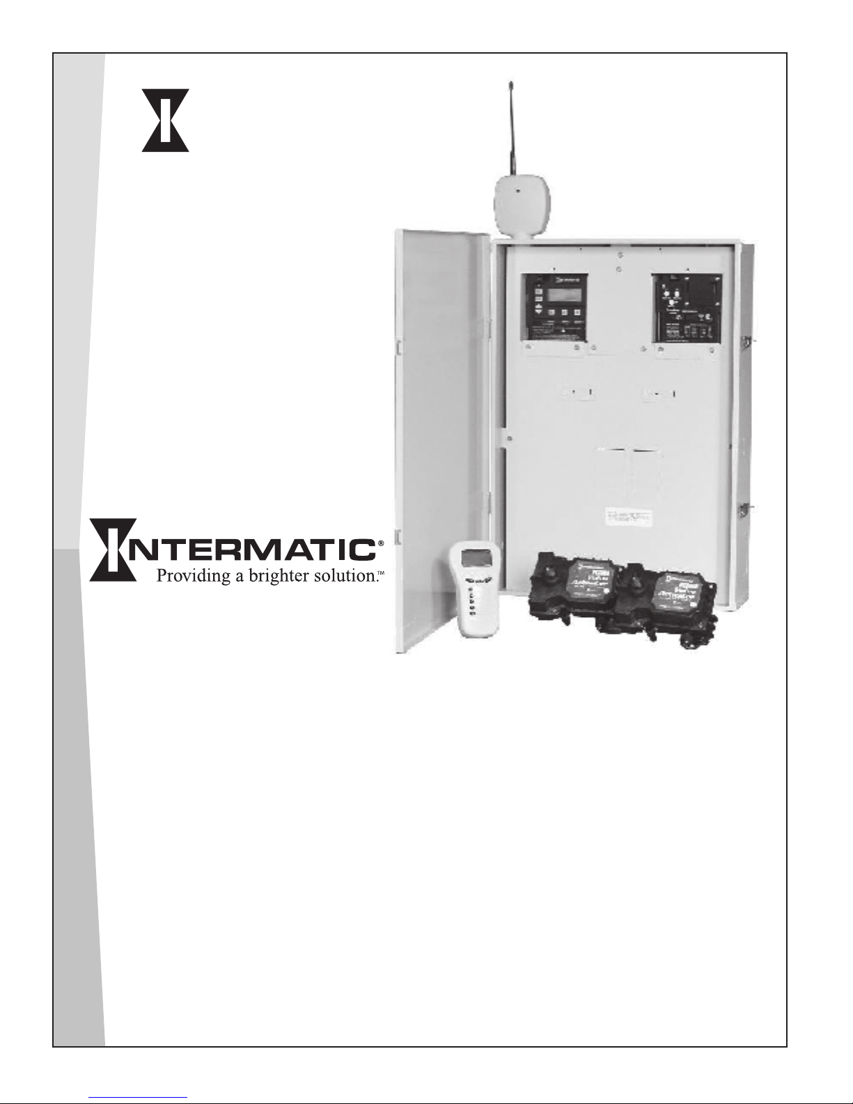
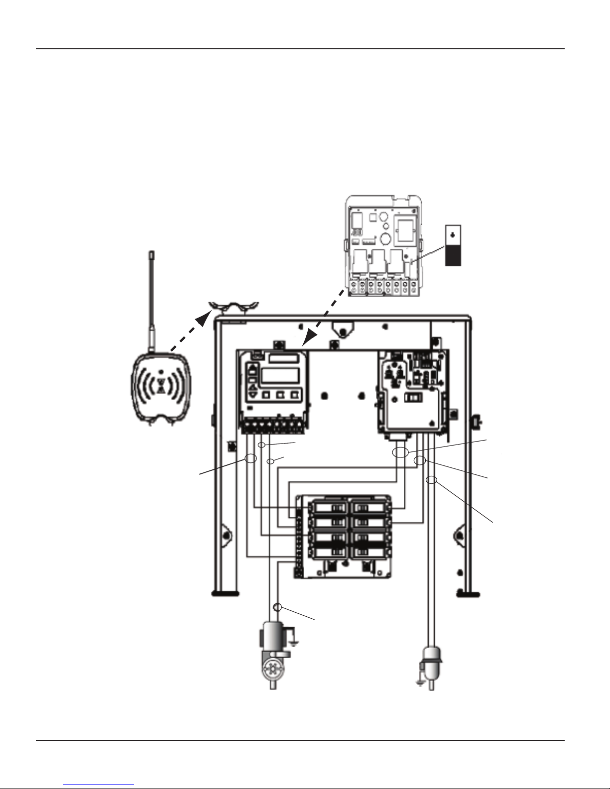
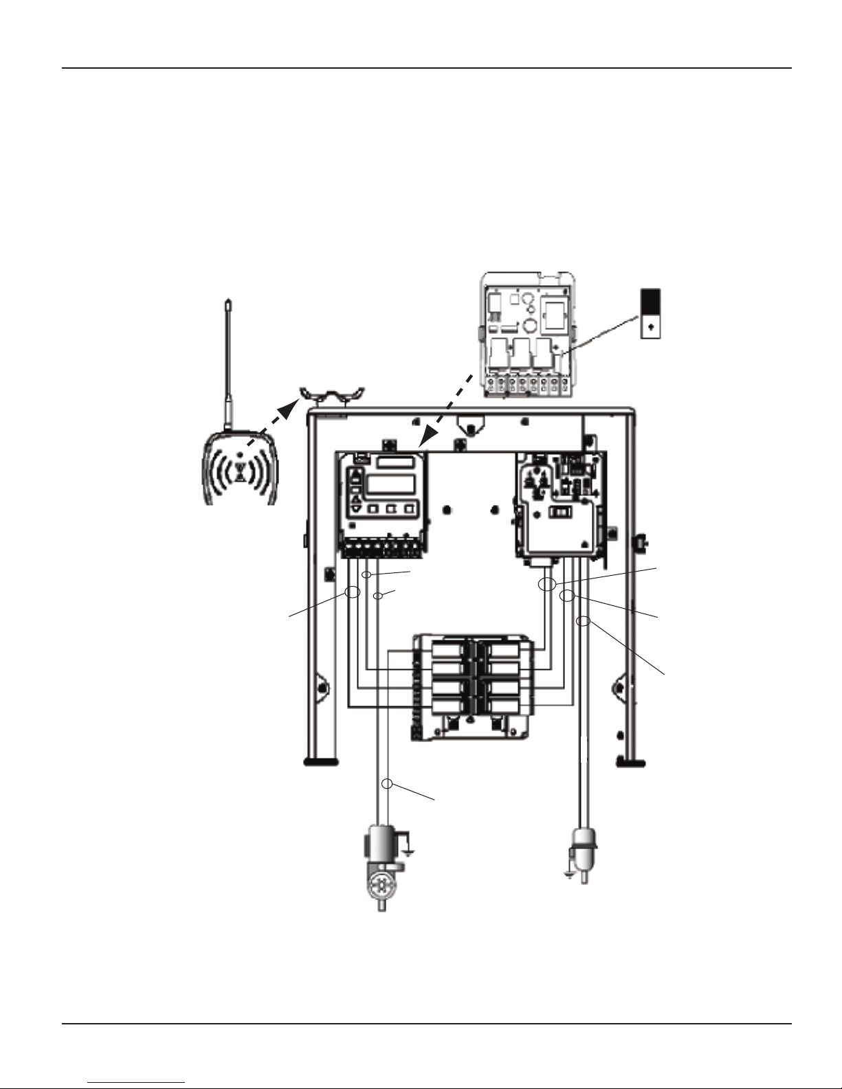
The standard conguration for the I-Wave Pool/Spa PE5 Wireless Control System conguration is
shown in Figure 1-1. You can order individual components for a custom conguration or system
as indicated.
Removable antenna (PA118)
Removable antenna (PA118)
can be ordered separately
can be ordered separately
Panel-Mounted Transceiver (PE650).
Panel-Mounted Transceiver (PE650).
Includes Antenna (PA118).
Includes Antenna (PA118).
Three-Circuit Clock (P1353ME)
Three-Circuit Clock (P1353ME)
offers timer capability and can
offers timer capability and can
control up to 3 pool/spa circuits.
control up to 3 pool/spa circuits.
Offers five pre-programmed
Offers five pre-programmed
configuration modes.
configuration modes.
Hand-Held Transceiver (PE950).
Hand-Held Transceiver (PE950).
Up to 5 units can be used with an
Up to 5 units can be used with an
I-Wave system. Additional units
I-Wave system. Additional units
can be ordered separately.
can be ordered separately.
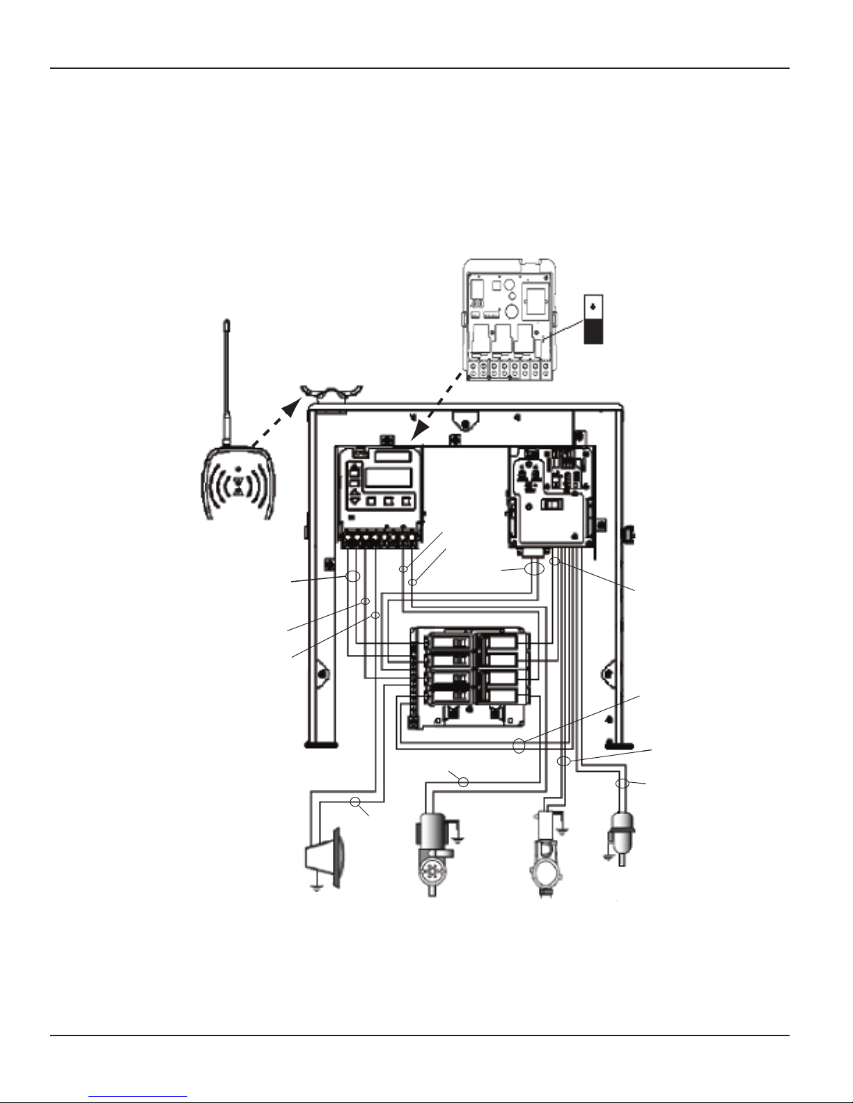
Valve/Pump Switch (P4243ME), can control
Valve/Pump Switch (P4243ME), can control
up to 2 different pool/spa circuits and up
up to 2 different pool/spa circuits and up
to 3 valve actuators. Can also be ordered
to 3 valve actuators. Can also be ordered
separately.
separately.
I-Wave Steel Outdoor Enclosure
I-Wave Steel Outdoor Enclosure
(PE40000), weatherproof, and with
(PE40000), weatherproof, and with
plenty of room to add additional
plenty of room to add additional
switch mechanisms if desirable.
switch mechanisms if desirable.
Can also be ordered separately
Can also be ordered separately
by installers who want to create
by installers who want to create
a non-standard system from
a non-standard system from
individual components.
individual components.
24-volt Valve Actuators (PE24VA)
24-volt Valve Actuators (PE24VA)
provide reliable control of 2-way
provide reliable control of 2-way
and 3-way diverter valves. (Two are
and 3-way diverter valves. (Two are
included, additional units can be
included, additional units can be
ordered)
ordered)
Figure 1-1Figure 1-1
Copyright © 2006 Intermatic, Inc.
Page 7
The standard system is shipped with snap-in mechanisms in place inside the enclosure, the
panel-mounted transceiver attached to the top of the enclosure, with antenna to be attached.
Components are already interconnected and are ready for wiring. System model numbers are
designed to make sure the installation meets local code as follows:
PE45343RC — the basic radio-controlled system.
•
PE45343RCT1 — a special version with a 100 watt transformer for 12-Volt underwater
•
lighting, where required by local code. The 100-watt transformer (PA117) can also be
ordered separately for installation into standard model PE45343RC.
PE45343RCT3 — a special version with a 300 watt transformer for 12-Volt underwater
•
lighting, where required by local code. The 300-watt transformer (PA116) can also be
ordered separately for installation into standard model PE45343RC.
You can order most system components individually to assemble a custom I-Wave system as
desired.
Additional Detail on Key Components
Three-Circuit Clock (P1353ME)
Designed for aftermarket and retrot applications, the P1353ME has the
ability to program up to three different circuits. Choose between six preprogrammed modes of operation, which include single speed pump or
2-speed pump/cleaner pump combinations. In addition, programmed
modes that include auxiliaries can control pumps up to 3 HP as well as
underwater, garden, and/or fountain lighting. Countdown and Override
features allow cycle interruptions when pool/spa service is required.
All timing and protection, associated with lter pump/cleaner pump
combinations and two-speed pumps, has already been integrated into
the software. This mechanism can also be installed into almost any
Intermatic enclosure.
One: System Overview 7
120 or 208-240 Volt Input Voltage
•
Memory Back-Up
•
Heater Protection (Fireman Switch)
•
LCD Readout
•
Shipping Weight — 3 lbs. (1.4 kg)
•
Agency Approval — CSA/C-US
•
CONTACT RATINGS – EACH CIRCUIT, ALL MODES
20A Resistive, 120/240 VAC., 50/60 Hz
•
20A FLA@120 VAC, 96A LRA@120 VAC, 50/60 Hz
•
17A FLA@240 VAC, 80A LRA@120 VAC, 50/60 Hz
•
5 Amps Tungsten, 120/240 VAC, 50/60 Hz
•
5 Amps Ballast, 120/240 VAC, 50/60 Hz
•
Providing a brighter solution.™
Page 8
8 I-Wave PE5 Installation Guide
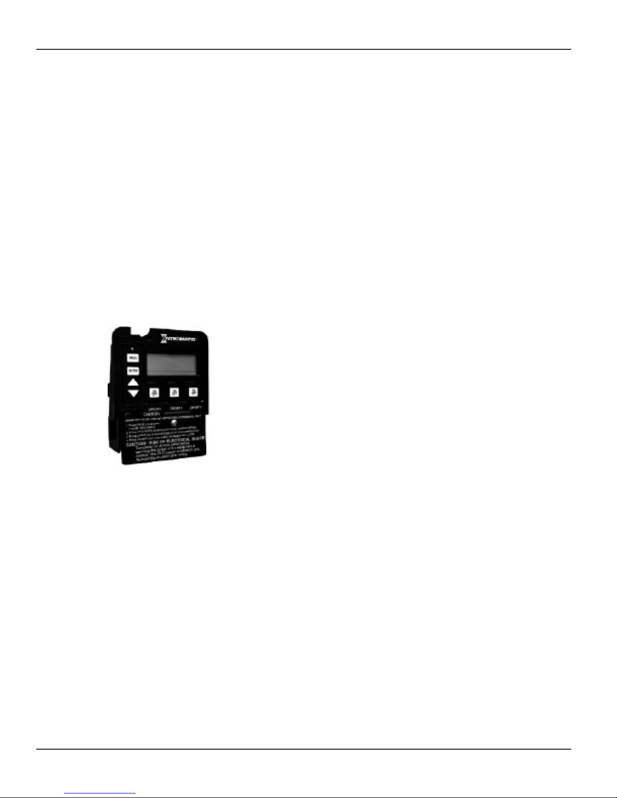
Valve/Pump Switch (P4243ME)
120 or 208-240 Volt Input Voltage
•
Controls up to three valve actuators
•
Switches heater thermostat
•
Remote control capabilities
•
Shipping Weight — 3 lbs. (1.4 kg)
•
Agency Approval — CSA/C-US
•
Designed for aftermarket and retrot applications, the P4243ME is most
suited for controlling up to two different circuits associated with pool/
spa combinations but can also be used to control all the equipment
typically needed in connection with water features, water gardening,
solar heating, and other similar applications. This unit snaps into almost
any Intermatic enclosure and features two 3HP double pole relays,
one of which can be controlled by an external timer, 24 volt supply for
up to three valve actuators, automatic HIGH/LOW water temperature
selector, heater connection circuit, and push button control for each
load with indicator lights on the face of the control. In addition, the unit
has connections for a hard-wired or wireless remote and a master switch
controller.
CONTACT RATINGS – EACH CIRCUIT
17A Resistive, 120/240 VAC., 50/60 Hz
•
1.5 HP @ 120 VAC., 50/60 Hz
•
3.0 HP @ 240 VAC., 50/60 Hz
•
10 Amp Tungsten, 120/240 VAC, 50/60 Hz
•
24-Volt Valve Actuator (PE24VA)
Designed with quality in mind, Intermatic’s 24-volt valve actuators
provide reliable control of 2-way and 3-way diverter valves for pool/
spa combinations and water features. The water ow can be altered
for specic applications through the adjustable cam, which rotates
diverter valves to multiple degree settings. The cam settings can be
easily adjusted by simply removing the lid. These valve actuators are
compatible with all pool/spa valves currently offered in the industry and
will retrot into all pool/spa control systems.
24VAC Input Voltage
•
Automates compatible diverter valves for
•
pool/spa combos
Adjustable cam rotates diverter valves to
•
multiple degree settings
Designed to operate most 2-way and 3-way diverter valves
•
Shipping Weight - 3 lbs. (1.4 kg)
•
Agency Approval - CSA/C-US
•
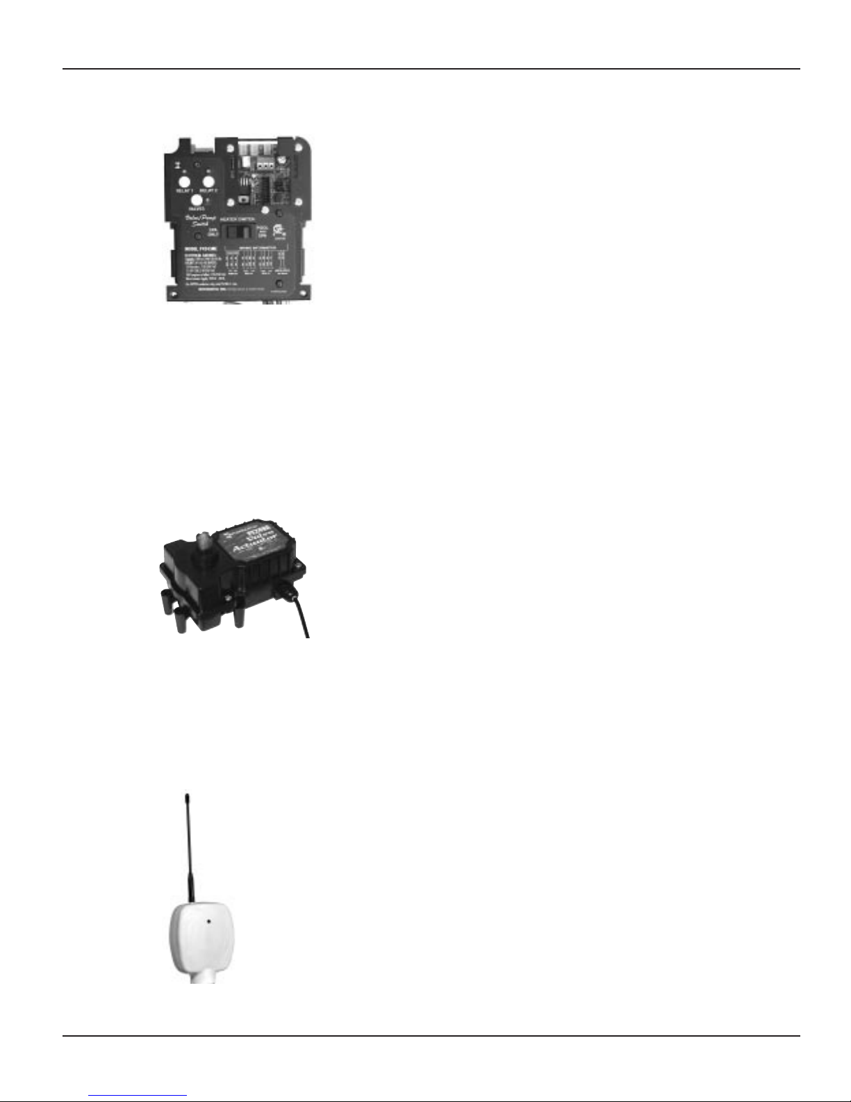
Panel-Mounted Transceiver (PE650) Includes Antenna (PA118)
The main function of the Panel-Mounted Transceiver is to take commands
from the Wireless Hand-Held Transceiver (PE950) and hand them off to two
mechanisms (P1353ME and/or P4243ME) in the I-Wave Enclosure box. This unit
can control:
One P1353ME unit and one P4243ME unit
•
•
•
In cases where the two devices are too far apart for direct communication, a
Transceiver Repeater Module (HA04C) will relay commands between the two
devices. Shown here with its removable antenna (PA118).
One or two P1353ME units
One or two P4243ME units
Copyright © 2006 Intermatic, Inc.
Page 9
One: System Overview 9
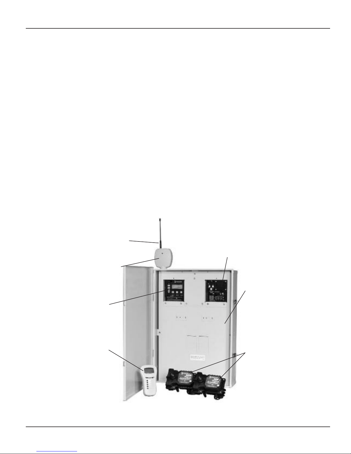
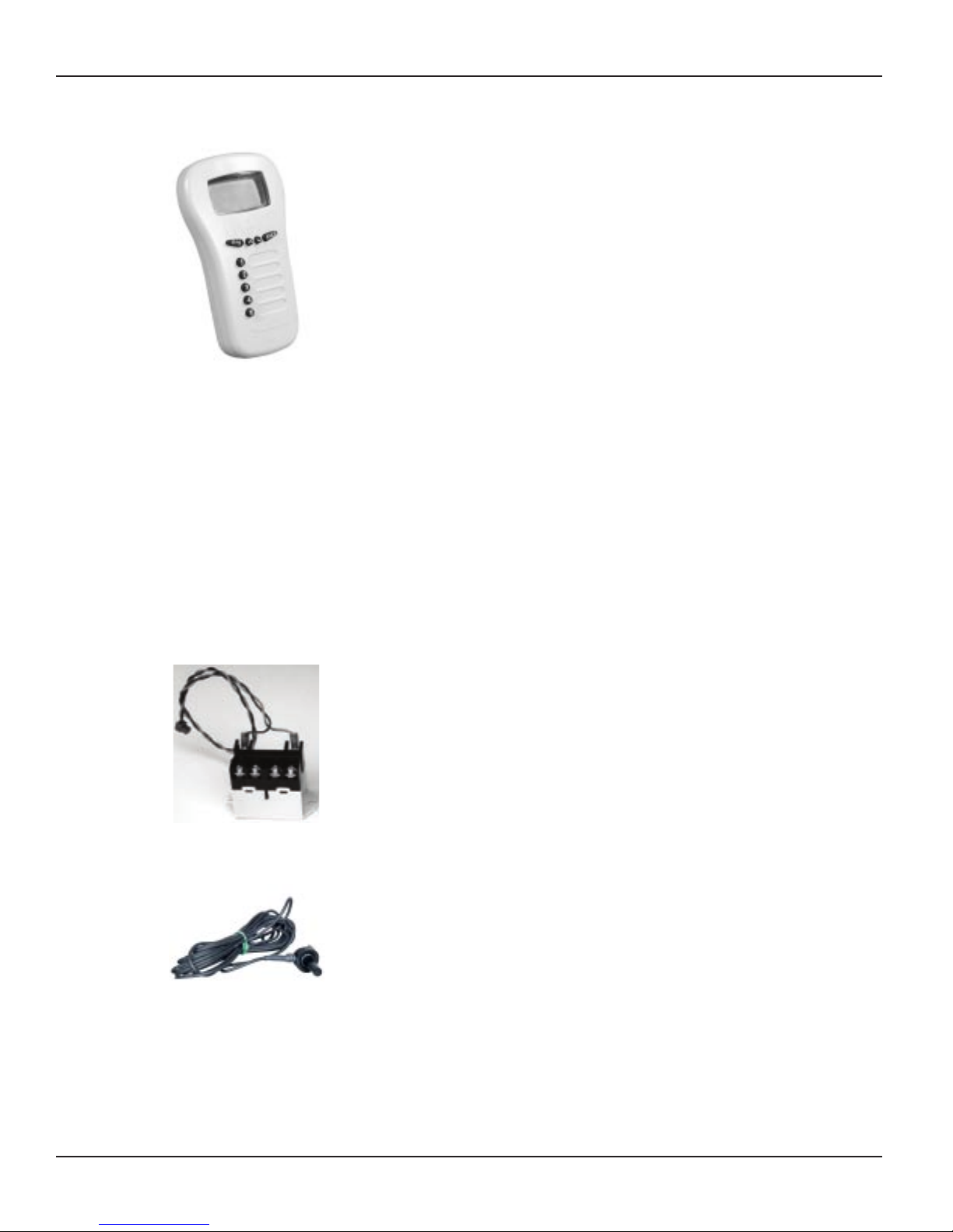
Wireless Hand-Held Transceiver (PE950)
The main function of the Wireless Hand-Held Transceiver is to transmit user
commands to the Panel-Mounted Transceiver (PE650) and display the status
of the equipment. The device can control up to ve loads, typically:
The three loads in the Three-Circuit Clock
•
The two relays in the Valve/Pump Switch, usually water temperature
•
controls for pool/spa
The actuators that switch between pool and spa
•
The unit oats if thrown in the pool or spa, is water-submersible, shock
resistant, and requires three (3) AA batteries. Expected battery life is about
one year in typical use.
The Wireless Hand-Held Transceiver (PE950) can only communicate with the Panel-Mounted
Transceiver (PE650) and Transceiver Repeater Module (HA04C), and is compatible with no
other hardware. In addition, when the components of a specic system are linked together into a
network, communication with another neighboring system cannot occur. Up to ve PE950 units
can be used in a single installation.
35-ft. Antenna Extension Cable Assembly (PA121)
When a structure impedes transmission between the Panel-Mounted Transceiver and Handheld Transceiver(s), you can use the 35-ft. Antenna Extension Cable Assembly (PA121) to
relocate the antenna from the Panel-Mounted Transceiver to the area of operation, ensuring that
communication between the Hand-Held unit and the control center is successful.
OMRON Relay Assembly (143T145A)
There are two OMRON Relay Assemblies (143T145A) in the Valve/Pump
Switch Mechanism (P4243ME) which switch either 120V or 240V loads.
These relays are replaceable and can be ordered separately.
CONTACT RATINGS – EACH CIRCUIT
CONTACT RATINGS – EACH CIRCUIT
17A Resistive, 120/240 VAC., 50/60 Hz
•
17A Resistive, 120/240 VAC., 50/60 Hz
•
1.5 HP @ 120 VAC., 50/60 Hz
•
1.5 HP @ 120 VAC., 50/60 Hz
•
3.0 HP @ 240 VAC., 50/60 Hz
•
3.0 HP @ 240 VAC., 50/60 Hz
•
10 Amp Tungsten, 120/240 VAC, 50/60 Hz
•
10 Amp Tungsten, 120/240 VAC, 50/60 Hz
•
Water Temperature Sensor (PA122)
The Intermatic Water Sensor (PA122) monitors both pool and spa water
temperature, depending on the position of the diverter valves. Installation
is necessary for the thermostatic control to work. The sensor can be
ordered separately.
Providing a brighter solution.™
Page 10
10 I-Wave PE5 Installation Guide
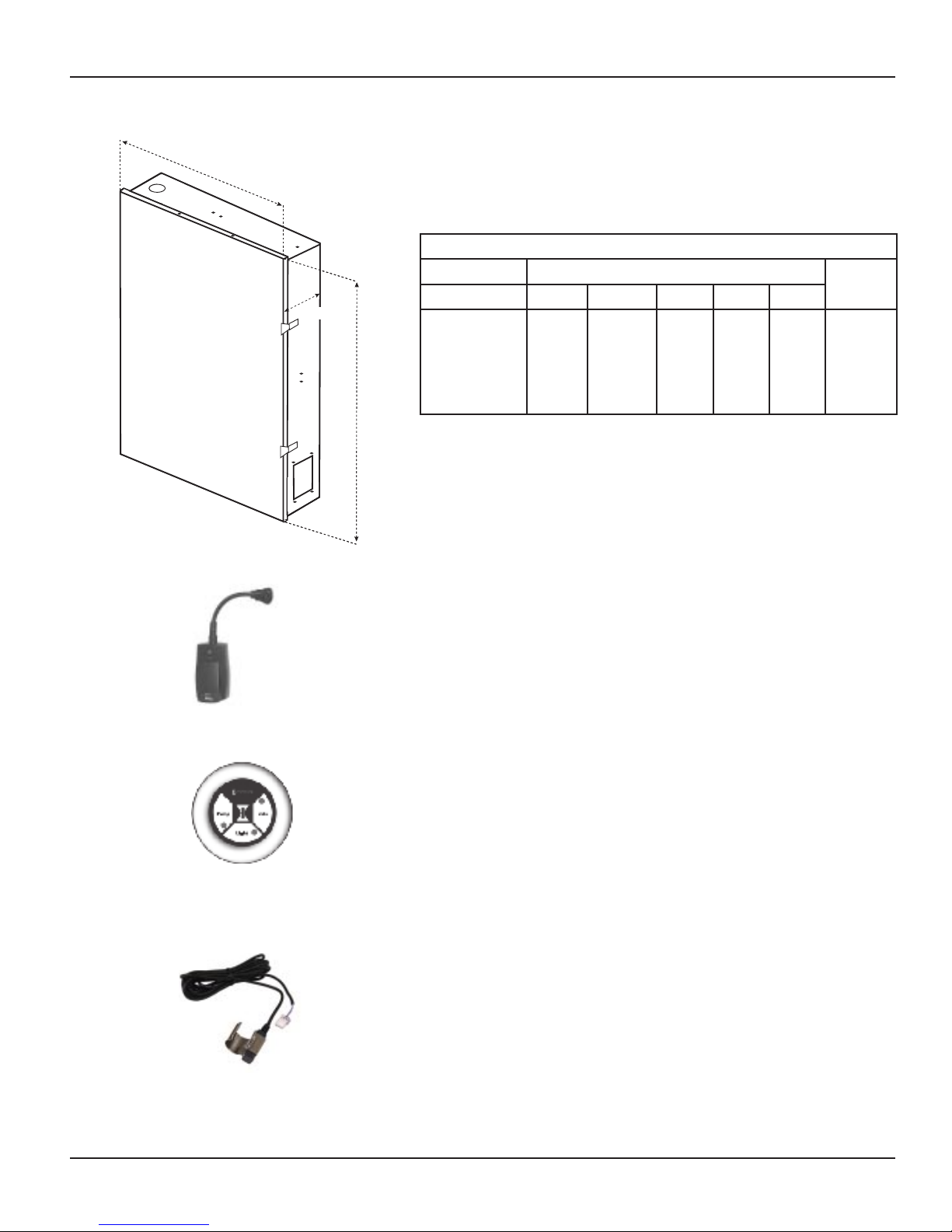
19”
26 3/4”
5 1/2”
19”
26 3/4”
5 1/2”
Steel Outdoor Enclosure Includes P1353ME (PE45300)
Suitable listed breakers (purchase locally)
CIRCUIT BREAKER FILLER
MFR SINGLE DOUBLE TWIN QUAD GFCB
Cutler-Hammer
Murray
Siemens
Square-D
Thomas & Betts
BR
MP-T
QP
HOM
TB
BR
MP-T
QP
HOM
TB
BRD
MH-T
QT
HOMT
TBBD
BRD
MH-T
QT
HOMT
TBBD
GFCB
MP-GT
QPF
HOMT
GFB
PLATE
BRFP
LX100FP
QF3
HOMFP
FP-1C-TB
Optional — Transceiver Repeater Module (HA04C)
The Transceiver Repeater Modules (HA04C) ensure that no problems in reception
occur between the Hand-Held Controller(s) (PE950) and the Panel-Mounted
Transceiver (PE650). Reception is affected by distance (about 100 feet, direct line
of sight) and by physical obstacles (like brick walls or structures). However, by
plugging in a Transceiver Repeater Module where necessary, long distances or
physical obstructions can be overcome.
Optional — Three-Button Wired Remote Control (133PE1484A)
The Three-Button Wired Remote Control (133PE1484A) plugs into either the
Three-Circuit Clock (P1353ME) or Valve/Pump Switch (P4243ME).
When installed as part of a system, it replaces the wireless method of controlling
the three circuits within the mechanism. For more information, refer to Installing
box, since the Wireless Hand-Held Transceiver (PE950) can only control two mechanisms.
Optional — Freeze (Air Temperature) Sensor (178PA28A)
a Wired Remote Connection in Section 4. The Three-Button Wired Remote
Control must be installed where a third mechanism is needed in the enclosure
Add the Intermatic Freeze or Air Temperature Sensor (178PA28A) to installations
where below-freezing outdoor temperatures are a concern. Programming
information to incorporate the sensor is provided on page 35.
Copyright © 2006 Intermatic, Inc.
Page 11
Section 2:
Pool
Spa
Filter
Check
Valve
Spa
Make-up
Filter
Pump
Intake
Return
Return
Intake
Skimmers
Heater
Pool
Spa
Filter
Check
Valve
Spa
Make-up
Filter
Pump
Intake
Return
Return
Intake
Skimmers
Heater
Pool
Spa
Filter
Check
Valve
Spa Make-up
Filter
Pump
Intake
Return
Return
Intake
Heater
Booster
Pump
Pool
Spa
Filter
Check
Valve
Spa Make-up
Filter
Pump
Intake
Return
Return
Intake
Heater
Booster
Pump
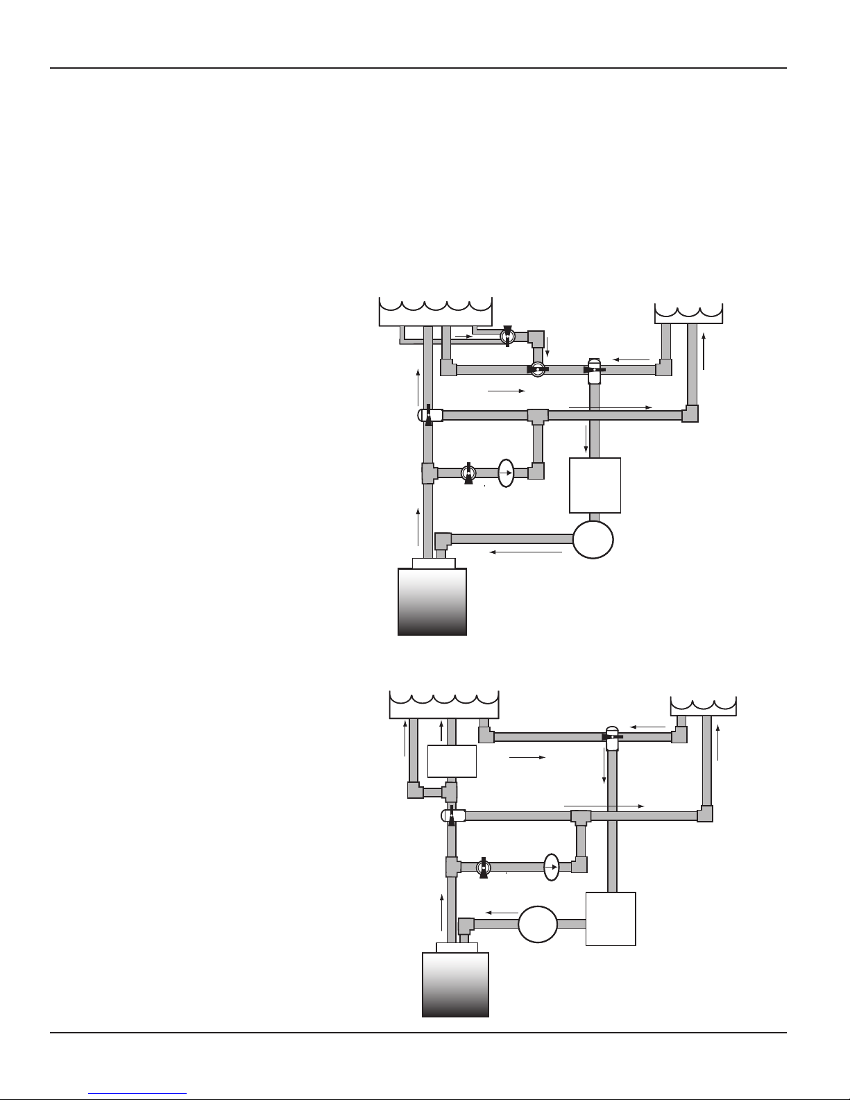
Plumbing Examples
The following diagrams show several plumbing and wiring examples of installations for pool and
spa that share a single lter pump, lter, and heater. If you are installing a pool only or spa only,
these diagrams will not apply.
For Pool and Spa
Combo Installations
Two: Plumbing and Wiring Examples 11
For Booster Pump Pool
Cleaner Installations
Providing a brighter solution.™
Page 12

12 I-Wave PE5 Installation Guide
Pool
Spa
Filter
Check
Valve
Spa
Make-up
Filter
Pump
Intake
Return
Return
Intake
Heater
Energy
Filter
Pool
Spa
Filter
Check
Valve
Spa
Make-up
Filter
Pump
Intake
Return
Return
Intake
Heater
Energy
Filter
For Non-Booster Pump
Pool Cleaner Installations
Copyright © 2006 Intermatic, Inc.
Page 13
Section 3:
Earth Ground
From Main
Power
White
(neu)
Black
Red
Ground
Buss
Earth Ground
From Main
Power
White
(neu)
Black
Red
Ground
Buss
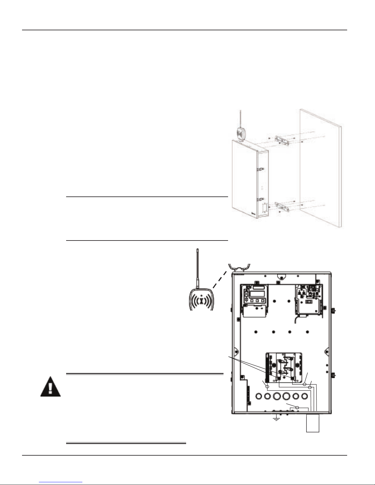
Control Center Installation
Mounting the Control Center
Special code requirements apply to your I-Wave
Control System. To ensure safe installation, please
follow all applicable national state, and local codes
when installing the Control Center.
Locate your Control Center near the pool/spa
equipment pad at least ve feet or more away from
either the pool or spa equipment and at least ve feet
off the ground.
Mounting brackets have been provided to assist you in
your installation.
NOTE: The Control Center is not to be considered
as suitable for use as Service Equipment. Therefore,
it is required to have the appropriate means of
disconnection, circuit isolation, and/or branch circuit
protection installed at the Main Power Panel.
Three: Control Center Installation 13
Figure 3-1Figure 3-1
Wiring the System Power
Run wire from the Main Power Panel
to your Control Center and connect the
leads to the Control Center Breaker Base.
See detail in Figure 3-2 at the right.
The breaker base of your Control Center
is capable of handling up to 125 amps.
You must comply with the applicable
local codes and use the proper gauge
wiring from your Main Power panel to
your control center breaker base. The
proper gauge wire will be determined by
the length of wire required and the 125
Max Amp rating.
WARNING: Potentially high voltages
in the Control Center can create
dangerous electrical hazards,
possibly causing death, serious
injury, or property damage. Turn
off the Main Power to the Control
Center to disconnect or service the
I-Wave Control Center.
Figure 3-2Figure 3-2
Providing a brighter solution.™
Page 14

14 I-Wave PE5 Installation Guide
Part Number
156T11047A
Part Number
156T11047A
Bonding the Control Center
Some state local codes require bonding the control center
to the bonding grid. If this is required, install a bonding lug
(156T11047A) to the Control Center enclosure and connect a
#8 solid copper core wire, to an approved earth ground, (i.e.
approved ground stake, or conducting metal water pipe buried
to a sufcient depth, etc.). See detail in Figure 3-3 at the right.
Wiring the Individual Equipment
Each piece of pool or spa equipment requires its own high voltage relay and associated circuit
breaker branch protection. Each circuit breaker should be sized according to your load and the
appropriate local codes.
The I-Wave Control System consists of two Intermatic snap-in mechanisms:
P1353ME — with three timed circuits each comprised of three SPST relays
•
P4243ME — with two on-demand circuits comprised of two DPST relays
•
Even though the three circuit clock can easily handle on-demand circuits, any equipment that
requires programmed ON/OFF times should be wired to the three-circuit P1353ME mechanism
(i.e., lter pumps, booster pumps, etc.). On-demand equipment (i.e., blowers, lights, etc.) should
be wired to the P4243ME valve-controller mechanism. This practice will maximize your control
capabilities.
All circuits are independent contacts. Therefore you can mix and match 120-Volt and 240-Volt
loads within each mechanism. Refer to the following illustrations for sample wiring diagrams.
Figure 3-3Figure 3-3
Copyright © 2006 Intermatic, Inc.
Page 15
If Wiring 120-Volt Loads:
If using 120V source voltage,
set voltage selector jumper
on back of P1353ME clock
mechanism to 120V
Breaker
Panel
Filter Pump
(120 VAC)
Neutral
Blower
(120 VAC)
Blk/Wht
120 VAC
Blk/Red
Line
Blu/Yel
Load
Blk/Wht
120 VAC
120V
240V
Blk (line)
Blk (load)
(P1353ME)
If using 120V source voltage,
set voltage selector jumper
on back of P1353ME clock
mechanism to 120V
Breaker
Panel
Filter Pump
(120 VAC)
Neutral
Blower
(120 VAC)
Blk/Wht
120 VAC
Blk/Red
Line
Blu/Yel
Load
Blk/Wht
120 VAC
120V
240V
Blk (line)
Blk (load)
(P1353ME)
For safety purposes, the factory default setting for the source voltage of a P1353ME
•
mechanism is for 240 Volts.
For 120-Volt installations, be sure you set the Source Voltage Selection Jumper on the back of
•
the Three-Circuit Clock mechanism (P1353ME) for 120 Volts before you begin wiring.
For more information, see Identifying Connections and Selecting Proper Input Voltage on
•
page 26.
Three: Control Center Installation 15
Figure 3-4Figure 3-4
Providing a brighter solution.™
Page 16
16 I-Wave PE5 Installation Guide
If using 240V source voltage,
set voltage selector jumper
on back of P1353ME clock
mechanism to 240V
Breaker
Panel
Filter Pump
(240 VAC)
Red
Blower
(240 VAC)
Blk/Org
240 VAC
Blk/Red
Line
Blu/Yel
Load
Blk/Red
240 VAC
120V
240V
Blk (line)
Blk (load)
(P1353ME)
If using 240V source voltage,
set voltage selector jumper
on back of P1353ME clock
mechanism to 240V
Breaker
Panel
Filter Pump
(240 VAC)
Red
Blower
(240 VAC)
Blk/Org
240 VAC
Blk/Red
Line
Blu/Yel
Load
Blk/Red
240 VAC
120V
240V
Blk (line)
Blk (load)
(P1353ME)
If Wiring 240-Volt Loads:
For safety purposes, the factory default setting for the source voltage of a P1353ME
•
mechanism is for 240 Volts.
The Source Voltage Selection Jumper on the back of the Three-Circuit Clock mechanism
•
(P1353ME) will already be correctly set, ready for you to begin wiring.
For more information, see Identifying Connections and Selecting Proper Input Voltage on
•
page 26.
Figure 3-5Figure 3-5
Copyright © 2006 Intermatic, Inc.
Page 17
If Wiring Combination 120- and 240-Volt Loads:
For combo 120- 240V loads,
set source voltage selector
jumper on back of P1353ME
clock mechanism to 120V
Filter Pump
(120 VAC)
Neu
Blower
(120 VAC)
Blk/Wht
120 VAC
Blk/Red
Line
Blu/Yel
Load
Blk/Wht
120 VAC
120V
240V
Blk (line)
Blk (load)
(P1353ME)
Blk (load)
Blk (line)
Vio/Org
Line
Blu/Gry
Load
Jet Pump
(240 VAC)
Light
(120 VAC)
Red
For combination 120- and 240-Volt loads, change the factory default setting of the Source
•
Voltage Selection Jumper on the back of the Three-Circuit Clock mechanism (P1353ME) from
its factory default setting to 120 Volts.
For more information, see Identifying Connections and Selecting Proper Input Voltage on
•
page 26.
Three: Control Center Installation 17
Figure 3-6Figure 3-6
Providing a brighter solution.™
Page 18
18 I-Wave PE5 Installation Guide
(WP1000C
)
(WP1000C
)
Wiring Underwater Lights
CAUTION: A Ground Fault Circuit Interrupter (GFCI) must be provided for high voltage
pool/spa lights. Do not use a GFCI circuit breaker.
High-Voltage Underwater Lights
Figure 3-7 Figure 3-8 Figure 3-7 Figure 3-8
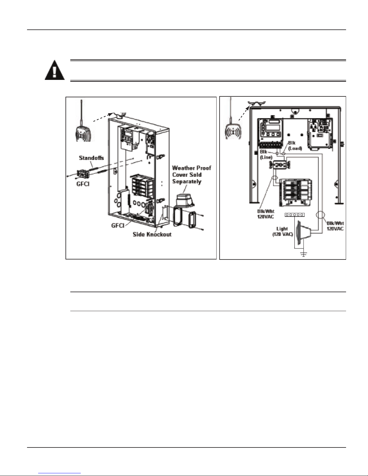
The I-Wave PE5 Control Center comes equipped with two décor knockouts on the dead front
and one side knockout for installation of GFCI receptacles. (See Figure 3-7).
NOTE: If using the décor knockouts to install a GFCI, you must use the standoffs provided with
the Control Center to mount your GFCI.
Install a GFCI receptacle and connect the neutral and hot wire, from the circuit breaker, to the
1.
LINE side of the GFCI. (See Figure 3-8).
Connect the neutral (white) from the light to the GFCI.
2.
Connect the hot (black) as follows:
3.
From the LOAD side of the GFCI to the line side of the clock,
a.
From the light to the LOAD side of the clock. (See Figure 3-8.)
b.
Connect the ground (green) from the light to the grounding bar inside the Control Center.
4.
Copyright © 2006 Intermatic, Inc.
Page 19
Three: Control Center Installation 19
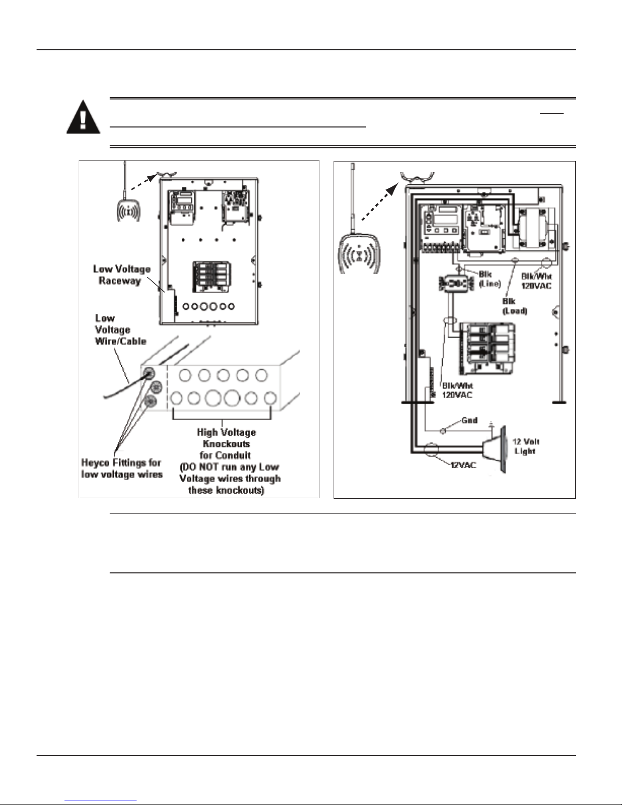
Low-Voltage Underwater Lights
CAUTION: Your I-Wave Control Center is equipped with a Low Voltage Raceway. You
must use this raceway for all low voltage wiring. You cannot mix high and low voltages
in the high voltage compartment.
Figure 3-9 Figure 3-10 Figure 3-9 Figure 3-10
NOTE: If you require a low voltage transformer, you should order system model PE45343RCT1
(with a 100 watt transformer) or PE45343RCT3 (with a 300-watt transformer). Alternatively, you
can order a 300-watt PA124 or 100-watt PA123 12V transformer kit to mount in the standard
system model PE45343RC. (See Figure 3-10.)
If required by local code, install a GFCI receptacle and connect the neutral and hot wire, from
1.
the circuit breaker, to the LINE side of the GFCI. (See Figure 3-10.)
Connect the light to the secondary side of the transformer.
2.
Connect the neutral (white) on the primary side of the transformer to the load side of the
3.
GFCI.
Connect the hot (black) as follows:
4.
To the LOAD side of clock,
a.
Then out the LINE side of the clock to the LOAD side of the GFCI. (See Figure 3-10.)
b.
Connect the ground (green) from the light to the grounding bar inside the Control Center.
5.
Providing a brighter solution.™
Page 20
20 I-Wave PE5 Installation Guide
Fireman’s Switch Wires
(Brown/Brown)
Water Temp Wires
(Black/White)
Make connection
with connectors
provided
Cable to
P1353ME
Cable to
P4232ME
Wires from
Water Temp Sensor
(Black/White)
(178PE4)
Fireman’s Switch Wires
(Brown/Brown)
Water Temp Wires
(Black/White)
Make connection
with connectors
provided
Cable to
P1353ME
Cable to
P4232ME
Wires from
Water Temp Sensor
(Black/White)
(178PE4)
Remove clock and connect
Freeze (Air Temp) Sensor
(178PA28A) here
Freeze Sensor
(178PA28A)
Remove clock and connect
Freeze (Air Temp) Sensor
(178PA28A) here
Freeze Sensor
(178PA28A)
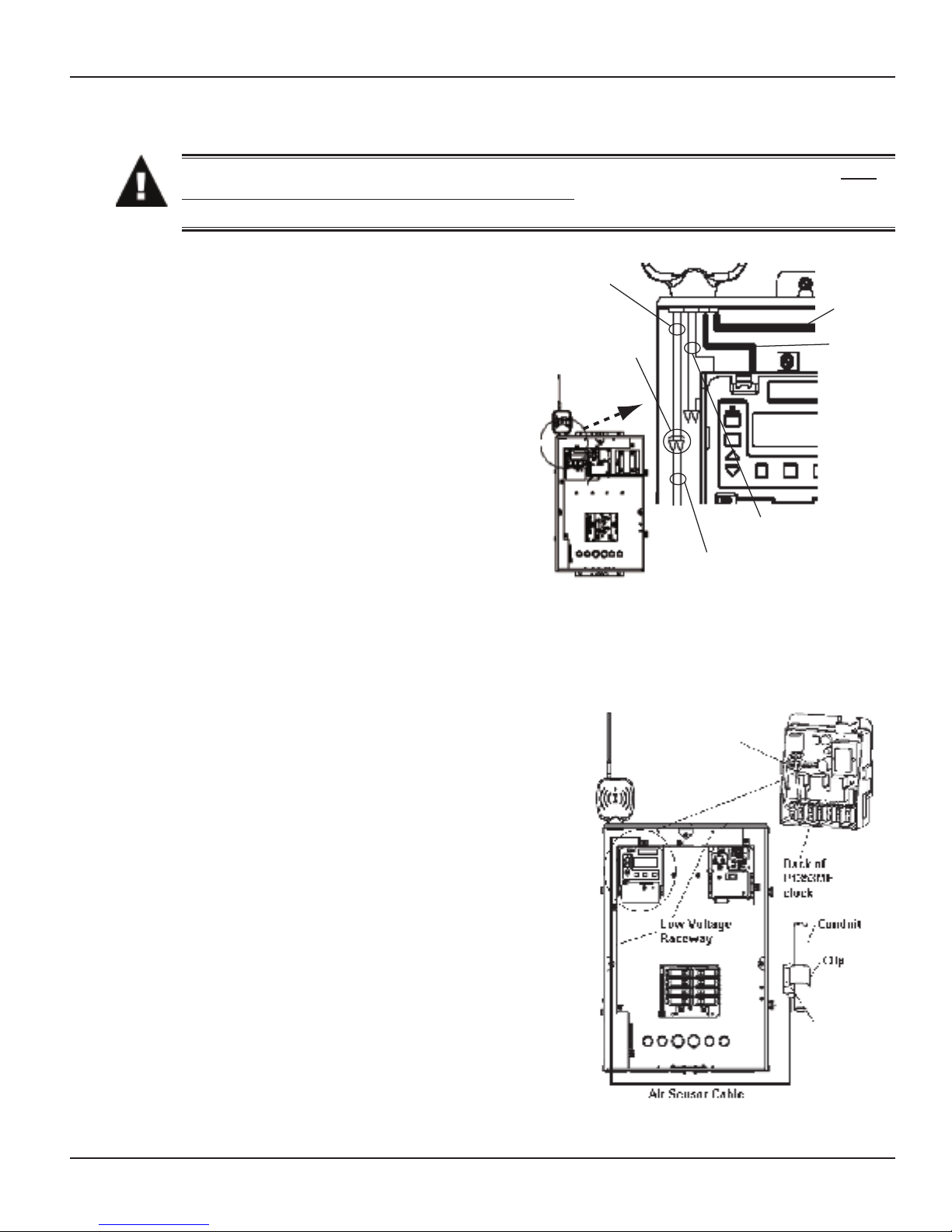
Low-Voltage Wiring
CAUTION: Your I-Wave Control Center is equipped with a Low Voltage Raceway. You
must use this raceway for all low voltage wiring, including the 12 Volt wires from the
transformer. You cannot mix high and low voltages in the high voltage compartment.
Water Temperature Sensor
The I-Wave Control System comes equipped
with a Water Temperature Sensor. This
sensor is needed to monitor and maintain
both the pool and spa water temperature
depending on the position of the diverter
valves. It needs to be installed in order for
the thermostat control to work. Power needs
to be disconnected when connecting the
temp sensor. Only an Intermatic Sensor
will work with this controller. Follow the
directions below to install and mount your
water temperature sensor. Refer to page 46
for programming instructions.
Drill a 3/8” hole in the pipe between the
1.
lter pump and lter and install the Water
Temperature Sensor with hose clamp (not
provided). Ensure the O-ring is in place.
Run the wire to the Control Center, through the low voltage raceway. Connect both wires to
2.
Figure 3-11Figure 3-11
the Panel-Mounted Receiver. (See Figure 3-11.)
Freeze Sensor
The I-Wave Control System uses an optional Freeze
Sensor (178PA28A) for measuring air temperature and
implementing the Freeze Protection Circuit—necessary
for the freeze protection circuit and programming to
work. Power must be disconnected when connecting
the Freeze Sensor. Only an Intermatic Freeze Sensor
will work with this controller. Refer to page 35 for
programming information, and page 10 for ordering
information.
Install the Freeze Sensor outside the Control Center,
1.
preferably onto a piece of conduit at or near your
equipment pad. Use the clip provided with the
sensor. Do not install in direct sunlight or around
motors or other heat sources.
Run the wire to the Control Center through the low
2.
voltage raceway. Connect Freeze Sensor directly
to the back of the three-circuit clock mechanism.
(See Figure 3-12.) Refer to page 26 for connection
information.
Figure 3-12Figure 3-12
Copyright © 2006 Intermatic, Inc.
Page 21

Three: Control Center Installation 21
Motorized Valve Actuator Connection and Synchronizing
The I-Wave Control System is capable of controlling up to three Motorized Valve Actuators. Two
Intermatic Motorized Valve Actuators (PE24VA) are included with your I-Wave system. Refer to
page 8 for information to order additional actuators.
The actuators must be installed to automatically rotate your valves between pool and spa
plumbing. Power must be disconnected when connecting the actuator connectors to your I-Wave
Control Center. Refer to the directions below prior to installing your PE24VA actuators. Refer to
Figure 3-13 for detail.
Figure 3-13Figure 3-13
Remove power from the I-Wave control center.
1.
Attach the valve actuators (PE24VA) to the water valves. (See instructions included.)
2.
Run the actuator cable to the Control Center, and through the low voltage raceway.
3.
Remove the access door to the Pump/Valve Switch mechanism.
4.
Insert the three-pin connector of the motorized valve actuator to any of the three available
5.
connectors on the Pump/Valve Switch mechanism circuit board.
Apply power to the I-Wave Control Center and synchronize the actuators as follows:
6.
Use the Valve button located on your Pump/Valve switch to illuminate the green light
a.
above the Valve button. This indicates that the switch is in SPA mode.
Use the switch located on your motorized valve actuator to ensure the valves are in the
b.
SPA position.
If either of the Actuators is positioned backwards, ip the switch on the back to reverse
c.
position.
Verify that the Actuators are correctly synchronized with your installation.
d.
Providing a brighter solution.™
Page 22

22 I-Wave PE5 Installation Guide
Fireman
Switch
Wires
(Brown/Brown)
Fireman
Switch
Wires
(Brown/Brown)
Fireman Switch Connection
The I-Wave Control System is capable of controlling most heaters or heat pumps, using
thermostatic circuitry of 24 VAC @ 2A or less, in the market today. Locate your heater in the
following pages and follow the instructions for proper installation with your I-Wave Control
Center.
Connection to the Three-Circuit Clock
Connect the Fireman switch to the Intermatic Fireman Switch
wires (tagged), located in the low-voltage raceway of the
Intermatic panel. (See Figure 3-14.)
Connection for Teledyne Laars Heater
Connect two #14 gauge wires, designed for
1.
Figure 3-14Figure 3-14
use in hot environments, to the two black
wires, marked heater connection, on the
panel-mounted receiver.
Connect the other ends of the #14 gauge
2.
wires from Step 1 to the Fireman’s Switch
terminal bar in place of the factory installed
wire loop.
Do not disconnect high limit or pressure
3.
switches.
Turn the heater thermostat(s) to maximum
4.
setting.
Turn the heater switch to the ON position.
5.
For dual thermostat heaters turn switch to Spa position.
Figure 3-15Figure 3-15
Connection for Raypak Heaters
The following connection procedure is for the two wire-one function conguration Raypak
heater.
Connect two #14 gauge wires, designed for
1.
use in hot environments, to the two black
wires on the panel-mounted receiver.
Connect one end of either #14 gauge wires
2.
from Step 1 to both the orange/black and
black/orange wires on the Raypak heater.
Connect the remaining #14 gauge wire
3.
from Step 1 to the yellow/black wire on the
Raypak heater.
Figure 3-16Figure 3-16
Copyright © 2006 Intermatic, Inc.
Page 23

Three: Control Center Installation 23
rs
Connection for Hayward Heaters
Remove heater service door on your Hayward
1.
Heater.
Remove factory-installed wire connector between
2.
two (2) red wires labeled “CONNECTION FOR
FIELD INSTALLED CONTROL SWITCH.” (See
Figure 3-17.)
Connect two #14 gauge wires, designed for use
3.
in hot environments, to the two red wires. (See
Figure 3-18.)
Wire the other end to the two black wires, marked
4.
Figure 3-17 — Wiring Before ModificationFigure 3-17 — Wiring Before Modification
heater connection, on the panel-mounted receiver
in your I-Wave Control Center.
Do not disconnect high limit or pressure switches.
5.
Turn the heater thermostat(s) to maximum setting.
6.
Turn the thermostat selector switch to the ON,
7.
HIGH, or SPA position.
Connection for Pentair Heater
Remove heater service door on your Pentair
1.
Heater.
Separate the black wires (common) from each
2.
other. (See Figure 3-19.)
Connect two #14 gauge wires, designed for use in
3.
hot environments, to the two black wires, marked
heater connection, on the panel-mounted receiver
in the I-Wave Control Center and attach the other
end to the two black wires on the heater. (See
Figure 3-20.)
Do not disconnect high limit or pressure switches.
4.
Turn the heater thermostat(s) to maximum setting.
5.
Turn the heater toggle switch on.
6.
Figure 3-18 — Wiring with [what??]Figure 3-18 — Wiring with [what??]
Figure 3-19 — Wiring Before ModificationFigure 3-19 — Wiring Before Modification
Figure 3-20 — Wiring with AquaLink RSFigure 3-20 — Wiring with AquaLink RS
Providing a brighter solution.™
Page 24

24 I-Wave PE5 Installation Guide
Connection for Sta-Rite Heaters
Figure 3-21 Figure 3-22 Figure 3-21 Figure 3-22
Turn off power to heater at main circuit breaker panel.
1.
Unbolt and remove the upper jacket
2.
halves (Refer to heater owners
manual).
3.
Open control box cover. (See
Figure 3-21.)
4.
Remove the factory-installed jumper
between the Fireman’s Switch
terminals. (See Figure 3-22. )
5.
Connect two #14 gauge
wires, designed for use in hot
environments, to the two black
wires, marked heater connection,
on the panel-mounted receiver
in the I-Wave Control Center and
attach the other end to the two
spade terminals at the heater. You
can also cut the yellow jumper wire
and wire connect the black wires to
each yellow wire. (See Figure 3-23.)
6.
Route the wires out through the
knockout on the bottom of the
Control Box.
7.
Do not disconnect high limit or
pressure switches.
8.
Turn the heater on and maximize
the temperature setting.
Figure 3-23Figure 3-23
Copyright © 2006 Intermatic, Inc.
Page 25

Four: Programming the Three-Circult Clock Mechanism 25
Section 4:
Programming the Three-Circuit Clock
Mechanism
Overview of Three Circuit Clock Control Panel
The Intermatic Three-Circuit Clock Control Panel is easy to program and capable of automatically
switching loads on three circuits according to a preset 24-hour daily schedule, and providing
control over a variety of different applications. Figure 4-1 shows the front of the mechanism.
MODE BUTTON—With a small tool, press and hold this button down
for 5 seconds. Using the Up and Down arrow keys, you can select the
appropriate preprogrammed mode that matches your particular pool or spa
equipment pad configuration. Hit the ENTER key when finished.
PROGRAM BUTTON—used to
enter programming mode and
access different programming
features.
ENTER BUTTON—used to
save programming changes
to memory and exit
programming mode.
ARROW BUTTONS—used
to increase or decrease
programming parameters
when in programming mode.
DISPLAY—Indicates time
of day and programming
settings during
programming mode.
ON/OFF BUTTONS—Turn
on and off circuit
functions.
Figure 4-1
TIMER POWER—the two terminals where you wire
120V or 240V to power the multipurpose control. Be
sure the jumper on the back, matches the source
voltage. See page 26.
CIRCUITS 1, 2, & 3—These six terminals are where you wire the equipment
source voltage and equipment load lines. You can have different source
voltages for each circuit, depending on your equipment requirements.
NOTE: The three-circuit clock breaks only one leg to the load. Wire the
other leg directly from the line to the load. (Refer to the illustration on the
clock, above the terminals.)
Providing a brighter solution.™
Page 26

26 I-Wave PE5 Installation Guide
Identifying Connections and Selecting Proper Input Voltage
Figure 4-2 below shows the reverse side of the Three-Circuit Clock Control Panel. Detailed
connection information is provided below the diagram.
CAUTION: If the Source Voltage Selector Jumper is in the wrong position, the F1 fuse
will blow and you may damage the circuit board, voiding the warranty.
Before making any connections: Set the Source Voltage Selector Jumper.
1.
The factory default position for this jumper is the 240 Volt position.
If the input voltage for the clock is 120 Volts, change this jumper to the
2.
120 Volt position.
Fireman Switch
Connection
Freeze Sensor
Connection
Source Voltage
Wired or Wireless
Remote Control
Connection
Figure 4-2
Selection Jumper
Fuse
Connection Detail
Freeze Sensor Connection — For the Intermatic Freeze Sensor (178PA28A), which is
•
necessary for the freeze protection circuit and programming to work. Disconnect power when
connecting the freeze sensor. Only an Intermatic sensor can be used. Refer to page 35 for
programming information.
Firemen Switch Connection — For the remen switch wires that connect to the Pool/Spa
•
heater. If installing with a Wireless Remote Control, use the two brown wires coming from the
panel-mounted receiver to create the circuit between this switch and the heater. Connectors
should be ¼” female spade connectors crimped to insulated-type wire. This connection is a
simple SPST contact, and switches the supplied heater voltage. It does not supply voltage to
the heater thermostat. In non-wireless installations, clip the “loop” supplied, then connect
with wire nut connectors. Refer to page 34 for programming information.
Remote Control Connection — Connects the Intermatic Remote Control (133PE1484A),
•
which allows you to remotely turn ON or OFF all three available circuits. It also has status
lights that indicate when a load is ON, OFF or delayed. If using the Three-Button Wired
Remote Control (133PE1484A), it connects here as well. Refer to page 38 for additional
information.
Copyright © 2006 Intermatic, Inc.
Page 27

Circuit Ratings
CLOCK SOURCE VOLTAGE — 120/240VAC, 50/60 Hz
POWER CONSUMPTION — 6.0 Watts Max
CIRCUIT CONTACT CONFIGURATION — SPST
CIRCUIT SWITCH RATINGS ALL MODES:
20A Resistive, 120/240 VAC, 50/60 Hz
•
20A FLA@120 VAC, 96A LRA@120 VAC, 50/60 Hz
•
17A FLA@240 VAC, 80A LRA@240 VAC, 50/60 Hz
•
5 Amps Tungsten, 120/240 VAC, 50/60 Hz
•
5 Amps Ballast, 120/240 VAC, 50/60 Hz
•
EVENTS PER CIRCUIT — 3 On/Off Events Per Circuit
INTERNAL BATTERY POWER:
40-year retention for all programmed settings
•
Up to 24 hours
•
Four: Programming the Three-Circult Clock Mechanism 27
Mode Selection/Definition
IMPORTANT NOTE—There are six modes to choose from, depending on your pool
or spa equipment pad configuration. Each mode has specific programming, timing,
and lockout features that are designed to work with specific types of pool or spa
equipment. Mode setting is generally done only once and usually during the initial
installation. It is purposely difficult to enter the mode-changing program and should
only be done by a Qualified Installer. Be sure you fully understand each mode
definitions and installation, prior to selecting the proper mode.
Mode 1 — (Aux1, Aux2, Aux3)
Each of the three single pole circuits are dened
generically, and can control any load within each
of its individual circuit ratings. All three circuits act
independent of each other.
NOTE: This drawing illustrates
NOTE: This drawing illustrates
that only one leg is broken, with
that only one leg is broken, with
the other leg going directly to
the other leg going directly to
load, whether 120V or 240V.
load, whether 120V or 240V.
Figure 4-3Figure 4-3
Providing a brighter solution.™
Page 28

28 I-Wave PE5 Installation Guide
Mode 2 — (Pump High, Pump Low, Aux3)
Circuit one and two are dedicated single pole
outputs for a two-speed pump load. Circuits one and
two will never be ON at the same time, consistent
with a two-speed pump application. Circuit
three is single pole circuit for a generic load, and
independent of circuits one and two.
NOTE: This drawing illustrates
NOTE: This drawing illustrates
that only one leg is broken, with
that only one leg is broken, with
the other leg going directly to
the other leg going directly to
load, whether 120V or 240V.
load, whether 120V or 240V.
Mode 3 — (Pump, Aux2, Cleaner Pump)
Circuit one and three are dedicated single pole
outputs for a single speed pump working with a
pressure side cleaner pump. Circuit three will never
come on unless circuit one is on for at least one
minute, consistent with a pressure side cleaner
pump. Circuit two is a single pole circuit for a
generic load, independent of circuits one and three.
NOTE: This drawing illustrates
NOTE: This drawing illustrates
that only one leg is broken, with
that only one leg is broken, with
the other leg going directly to
the other leg going directly to
load, whether 120V or 240V.
load, whether 120V or 240V.
Figure 4-4Figure 4-4
Figure 4-5Figure 4-5
Copyright © 2006 Intermatic, Inc.
Page 29

Four: Programming the Three-Circult Clock Mechanism 29
Mode 4 — (Pump High, Pump Low, Cleaner Pump)
Circuit one and two are dedicated single pole
outputs for a two-speed pump load. Circuits one and
two will never be ON at the same time, consistent
with a two-speed pump application. Circuit three
is also a dedicated single pole output for a pressure
side cleaner pump. Circuit three will never come
on unless circuit one is on for at least one minute,
consistent with a pressure side cleaner pump.
NOTE: This drawing illustrates
NOTE: This drawing illustrates
that only one leg is broken, with
that only one leg is broken, with
the other leg going directly to
the other leg going directly to
load, whether 120V or 240V.
load, whether 120V or 240V.
Figure 4-6Figure 4-6
Mode 5 — (Pump, Pump, Aux3)
Circuit one and two are now coupled together
making up one circuit capable of switching the
power source to one pump. The On/Off button for
circuit one now controls both circuit one and two
simultaneously. The On/Off button for circuit two is
disabled. Circuit three remains a single pole circuit
for a generic load, and is independent of circuits one
and two.
NOTE: This drawing illustrates
NOTE: This drawing illustrates
that only one leg is broken, with
that only one leg is broken, with
the other leg going directly to
the other leg going directly to
load, whether 120V or 240V.
load, whether 120V or 240V.
Figure 4-7Figure 4-7
Providing a brighter solution.™
Page 30

30 I-Wave PE5 Installation Guide
<Mode> button
<ENTER> button
“SET MODE”
<Arrow>
buttons
Circuit outputs will
be defined
Mode
Number
blinks
<Mode> button
<ENTER> button
“SET MODE”
<Arrow>
buttons
Circuit outputs will
be defined
Mode
Number
blinks
Mode 6 — (Aux1, Aux2, Aux3)
Identical to Mode 1, in which each of the three single
pole circuits are dened generically and can control any
load within each of its individual circuit ratings, with all
three circuits act independent of each other.
However, with Mode 6, the reman switch closes only
when Circuit 1 (the lter pump) is manually turned on
— not when the clock turns it on. This mode is useful
when you have Circuit 1 connected to a circulation
pump in the spa. When the spa is not in use, the clock
circulates the water to lter it, but does not turn on the
heater. When the spa is in use, the heat is also turned on
by manually switching Circuit 1.
NOTE: This drawing illustrates
NOTE: This drawing illustrates
that only one leg is broken, with
that only one leg is broken, with
the other leg going directly to
the other leg going directly to
load, whether 120V or 240V.
load, whether 120V or 240V.
Setting Mode
Figure 4-8Figure 4-8
Overview
Determine the mode that would be best for your installation, then select it using the instructions
provided below.
Procedure
NOTE: If you don’t press a button within 60 seconds
while setting Mode, the control will save current
settings and return to normal operating mode.
With a small pointed tool (i.e., pen, pencil,
1.
screwdriver, etc.), press and hold the <MODE>
button for about 5 seconds until the display
shows SET MODE and the Mode Number
blinks.
Use the <Arrow> buttons to cycle through all
2.
ve available modes. Each circuit output will
be dened on the display as you cycle through
the available modes.
Once the desired mode number is displayed,
3.
press and release the <ENTER> button. This
saves the mode number to memory and exits
SET MODE programming.
Copyright © 2006 Intermatic, Inc.
Page 31

Setting Time of Day
<PROGRAM>
button
Program Menu
Displayed Time
<Arrow>
buttons
AM/PM Indicator
<PROGRAM>
button
Program Menu
Displayed Time
<Arrow>
buttons
AM/PM Indicator
NO EVENT 1 Not definedNO EVENT 1 Not defined
Overview
This procedure makes sure that timer-controlled actions will occur at the right time.
Procedure
NOTE: If you don’t press a button within 60 seconds
while setting Time of Day, the control will save
current settings and return to normal operating mode.
Press and release the <PROGRAM> button. The
1.
displayed time will start to blink, and the program
menu will display Set Clock.
Use the <Arrow> buttons to change the time.
2.
NOTE: Check the AM and PM indicator to make
sure your setting is correct.
When the time is set, you have two choices:
3.
Four: Programming the Three-Circult Clock Mechanism 31
Press and release the <ENTER> button to save and exit programming.
•
Press and release the <PROGRAM> button to save and go on to the next programming
•
feature.
Setting the On/Off Times for Each Circuit
Overview
You can set up to three separate ON/OFF times per load or circuit, and you can set specic times
for them to turn on and off, i.e., you want the lter pump to run from noon till 4:00 P.M., or you
want lights on from 7:00 P.M., off at 11:00 P.M., then on again at 6:00 A.M. and off at 8:00 A.M.
Procedure
PROGRAMMING TIP: You can use the <ENTER> button to review all the events for each circuit.
You can use the <PROGRAM> button to advance through each circuit and on to the next
programming feature.
If you pressed and released the program key from
1.
the previous procedure, the screen display should
look like the illustration at the right. [If not, press and
release the <PROGRAM> button twice.]
Note that the display indicates that the rst event of
circuit one has not been dened (NO EVENT1).
Providing a brighter solution.™
Page 32

32 I-Wave PE5 Installation Guide
First Event
(EVENT1)
Start Time
First Event
(EVENT1)
Start Time
Stop Time
First Event
(EVENT1)
Stop Time
First Event
(EVENT1)
NO EVENT 2NO EVENT 2
Use the <Arrow> buttons to dene the Start time for
2.
the rst event (EVENT1) for circuit one. The screen
displays:
Once you are satised with the start time, press and
3.
release the <ENTER> button, saving the start time. The
display will prompt for the Stop time for the rst event
(EVENT1) for circuit one. The screen displays:
Use the <Arrow> buttons to dene the Stop time
4.
for the rst event (EVENT1) for circuit one. Press
and release the <ENTER> button when complete.
The program will now advance to the second event
(EVENT2) for circuit one, as shown below. Note that
the display indicates that the second event of circuit
one has not been dened (NO EVENT2).
Repeat Steps 2 thru 4 to set a second event for circuit
5.
#1, and for subsequent events you wish to set up.
Notes on Setting ON/OFF Times for Each Mode
General Note
The ON/OFF buttons were provided for service operations, and for circumstances where
•
instantaneous response is required. If the intent is to turn equipment on and off everyday at
the same time, programming individual events will make sure these functions take place.
All circuits will respond to a programmed off time. Therefore, when a circuit is turned on with
•
the ON/OFF button, it automatically turns itself off at the end of the next programmed event.
If there are no events programmed, the circuit stays on until the ON/OFF button is pressed
•
again.
If the ON/OFF button is pressed while the corresponding circuit is on, it turns the circuit
•
off and supersedes any program in progress. The priority is always given to the last manual
operation.
Copyright © 2006 Intermatic, Inc.
Page 33

Four: Programming the Three-Circult Clock Mechanism 33
Notes on Setting ON/OFF Times for Each Mode (cont’d)
Mode 1 — (Aux1, Aux2, Aux3)
All three of the available circuits act independently, and up to three individual on/off times can
be set for each circuit independently.
Mode 2 — (Pump High, Pump Low, Aux 3)
In this mode circuits 1 & 2 are connect to a two speed pump, and Aux 3 is connected
independent of circuits 1 & 2. In the event that you program high and low speed to be on at the
same time or if their independent ON times overlap, high speed will always take precedence.
Example: Low speed is programmed to come ON at noon and run until 6 PM. High speed is
programmed to come on at 2 PM and turn off at 4 PM. In this case the pump will come ON
at noon in low speed, go to high speed at 2 PM, and back to low speed at 4 PM, and shut off
at 6 PM.
All manual ON operations for circuits 1 & 2 override all programmed ON times. Therefore, any
desired low and high-speed run combinations need to be programmed as separate events and
cannot controlled by combining the manual ON/OFF button with a scheduled event. The last
speed started manually has priority over all prior automatic and manual operations.
Example: You would like to run the pump in high speed for 6 hours and low speed for the
remainder of the time. Program a 6-hour event for high speed, and an 18-hour event for low
speed. Do not turn the low speed on manually, and program a 6-hour event for high speed.
The high speed will not occur.
Mode 3 — (Filter Pump, Aux2, Cleaner Pump)
The cleaner pump cannot turn on unless the lter pump has been on for at least 30 seconds.
Therefore, for any ON/OFF time programmed for the cleaner pump, the lter pump will come on
rst, followed 30 seconds later by the cleaner pump. Both the cleaner and lter pump will turn
off according to the programmed off time. When programming an event for the cleaner pump, it
is not necessary to program a separate event for the lter pump, as it will automatically turn on
when the cleaner pump turns on at its next scheduled on time.
Mode 4 – (Pump High, Pump Low, Cleaner Pump)
Mode 4 is a combination of Modes 2 and 3, so refer above to Modes 2 and 3 for programming
specics. Note that if the cleaner pump is programmed to come ON, the control will turn ON
the lter pump to high speed 30 seconds prior to turning the cleaner pump ON, even if the lter
pump is currently on in low speed.
Mode 5 – (Aux1, Aux3)
Both of the available circuits act independently, similar to Mode 1. Therefore you can set up to
three individual ON/OFF times for each circuit and they will act independently.
Mode 6 — (Aux1, Aux2, Aux3)
All three of the available circuits act independently, and up to three individual on/off times can
be set for each circuit independently. When the clock turns ON Circuit #1 due to a scheduled
ON time, the heater will not come on. The heater will come ON only when Circuit #1 is turned
ON manually.
Providing a brighter solution.™
Page 34

34 I-Wave PE5 Installation Guide
COOL DOWN
<PROGRAM> button
<ARROW> buttons
COOL DOWN
<PROGRAM> button
<ARROW> buttons
Counting Down
Minutes and Seconds
AUX1 Indicator
Blinking
Counting Down
Minutes and Seconds
AUX1 Indicator
Blinking
Setting the Heater’s Cool Down Time (optional)
Overview
The heater’s cool down time is a time dened by the programmer. This time is dened as the
additional time the pump will run, over and beyond the desired pump OFF time, to make sure
the heater is cooled down before shutting off.
If the heater were to stay on after the pump had shut off, the water in the pipe could
boil, damaging the system. Refer to heater manufacturer for specific time.
If a cool down time is programmed, the cool down cycle will occur in all cases, even if the user
turns off the pump. To override the cool down time, press and release the ON/OFF key a second
time during the cool down cycle. The cool down feature only applies to Circuit #1, in all modes.
Procedure
Use the <PROGRAM> button to advance to the COOL
1.
DOWN setting, as shown. The default cool down time
is zero.
Use the <ARROW> buttons to modify the cool down
2.
time. The programming range is from zero to fteen
minutes and no seconds.
When you’ve set the cool down time, press the
3.
<ENTER> button to save and exit, or the <PROGRAM>
button to save and advance to the next programming feature.
The display will look like the example shown at the right
when the Heater’s Cool Down Time feature is activated. In
this example, the cool down time was set for 5 minutes,
and is in the process of counting down to zero, showing
minutes and seconds.
The AUX1 indicator is blinking, indicating that the Cool
Down feature is activated for Circuit #1. The Cool Down
feature only affects Circuit #1. When the countdown
display reaches zero, Circuit #1 will open and the time
display will change back to the time of day.
NOTE: You can override the Cool Down feature during countdown by pressing and releasing the
ON/OFF button associated with Circuit #1. This will end the cool down cycle and immediately
power off Circuit #1.
Copyright © 2006 Intermatic, Inc.
Page 35

Four: Programming the Three-Circult Clock Mechanism 35
32°F
Freeze Temp
1st Circuit
32°F
Freeze Temp
1st Circuit
Aux #1 and #3
Freeze
Aux #1 and #3
Freeze
Setting Freeze Temperature (optional)
Overview
Freeze temperature programming will not appear unless the optional Intermatic Freeze Sensor
(178PA28A) has been installed. This is the only freeze sensor that will work with the P1353ME
Mechanism.
Power must be disconnected when connecting the 178PA28A sensor.
If Intermatic Freeze Sensor (178PA28A) has been installed, use the following procedure to
program freeze temperature.
Procedure
Use the <PROGRAM> button to advance to the
1.
Freeze Temp setting, as shown. The 1st Circuit and
32°F are the factory default settings.
Use the <ARROW> buttons to modify the desired
2.
freeze temperature trip point. The programming range
is 32° through 44°F.
After you have set the desired trip temperature, push
3.
and release the desired ON/OFF button to indicate
which circuits should come ON when the trip temperature is reached.
When programming is complete, , press the <ENTER> button to save and exit, or the
4.
<PROGRAM> button to save and advance to the next programming feature.
The display will look like the example shown at the
right when the Freeze Control feature is activated. In
this example, the freeze sensor was connected, enabling
the Freeze Control feature. Circuits #1 and #3 were
programmed to come on during a Freeze condition.
AUX1 and AUX3 will blink, indicating that the control
has activated these two circuits due to a freeze condition.
NOTE: You can override the circuits during a freeze condition by pressing and releasing the
corresponding ON/OFF buttons. This will turn the devices OFF. The override will only last one
hour, so if the freeze condition still exists after one hour, Circuits #1 and #3 will come back on.
NOTE: Freeze protection stays enabled until the outside air temperature exceeds the
programmed freeze temperature for more than one minute.
Providing a brighter solution.™
Page 36

36 I-Wave PE5 Installation Guide
Section 5:
Programming the Valve/Pump Switch
Mechanism
Overview of the Valve/Pump Switch Control Panel
Front View
HEATER THERMOSTAT CONNECTOR — supports the three
ACTUATOR CONNECTION —
The Valve/Pump Switch
mechanism supports up to
three 24V valve actuators.
SERVICE BUTTONS —
allow you to operate the
mechanism at the panel.
wires from the heaters thermostat. The wires should be
marked Pool, Common, and Spa. The mechanism will
switch the heater thermostat when the actuators change.
WIRED OR WIRELESS
CONNECTOR will support
either the wired remote
control or the panel-mounted
wireless transceiver.
POOL/SPA
THERMOSTAT SWITCH
— allows you to switch
between the pool and
spa thermostat or just
the spa only. In the spa
only mode, the pool
thermostat is disabled.
DUAL-VOLTAGE TRANSFORMER
— is capable of being powered
with either 120V or 240V.
CIRCUITS 1 & 2 — The pool to spa mechanism
supports up to two auxiliary 3HP circuit loads. You
can have different source voltages for each circuit,
depending on your equipment requirements.
JUMPER BLOCK
CONFIGURATION — used
when a simple single-pole
single through switch
is going to be used in
conjunction with the Sensor
Line to control the Pool to
Spa Mech. This is the most
inexpensive way to achieve
total pool/spa automation.
SENSOR LINE — allows the
mechanism to be controlled by
a single pole sing throw switch
(i.e. toggle switch, relay, wall
switch, etc.). See page 38 for
details.
Copyright © 2006 Intermatic, Inc.
Page 37

24 VAC POWER-IN FOR PC
BOARD — The secondary of the
Valve/Pump Switch transformer
supplies 24 VAC to the circuit
board at these two pins.
OMRON CONNECTIONS
— Each of the two Omron
relay coils connect to the
PC board at these points.
Be careful not to switch
the two connectors, as the
relays will not match up
with the front membrane
pad on the mechanism
SENSOR LINE PLUG IN — This is where the two sensor lines
connect to the PC board. The sensor line allows the mechanism
to be controled by a single-pole, single-throw switch or master
switch (i.e., a toggle switch, relay, wall switch, etc.). See page 38.
HEATER SWITCH CONNECTION — The POOL/SPA & SPA ONLY
switch, located on the face of the Valve/Pump Switch mechanism,
interfaces with the PC board at this point.
EXTERNAL TIMER PLUG IN —
An external dry-contact
timer connects at this point
to control the ON/OFF state
of Relay #1. See page 40.
OMRON RELAY #2 — This
relay is a DPST relay
capable of controlling
up to a 3 H.P. load and
17 FLA @ 240 VAC.
Can be ordered separately
(145T145A). See page 9.
CONTROL FACE PLUG IN — The
front membrane control pad
control pad plugs into the
PC board at this point.
OMRON RELAY #1 — This
relay is a DPST relay
capable of controlling up to
a 3 H.P. load and
17 FLA @ 240 VAC. Can be
ordered separately (145T145A).
See page 9.
Rear View
Five: Programming the Valve/Pump Switch Mechanism 37
Providing a brighter solution.™
Page 38

38 I-Wave PE5 Installation Guide
Installing the Three-Button Wired Remote Control
The Three-Button Wired Remote Control (133PE1484A) can be installed to plug
into either the Three-Circuit Clock (P1353ME) or Valve/Pump Switch (P4243ME).
When plugged into one of these mechanisms, it replaces the wireless method of
controlling the three circuits within the mechanism. For example, if you plug the
Three-Button Wired Remote Control into the Valve/Pump Switch, the two relays
and the actuators will no longer be controllable using the Hand-Held Wireless
Remote. The Three-Button Wired Remote Control must be installed where a third
mechanism is needed in the enclosure box, since the Wireless Hand-Held Remote Transceiver
can only control two mechanisms.
See illustrations below for connection detail.
Connection to
Connection to
Valve/Pump Switch
Valve/Pump Switch
(PE4243ME)
(PE4243ME)
Three-Button Wired
Three-Button Wired
Remote Control
Remote Control
(133PE1484A)
(133PE1484A)
Connection to
Connection to
Three-Circuit Clock
Three-Circuit Clock
(PE1353ME)
(PE1353ME)
Installing Other Wired Remote Connections (Master Switch)
You can install any ON/OFF switch to the sensor line to provide wired control of the two relays
and the Pool/Spa actuators in the Valve/Pump Switch (P4243ME), giving you dual control
(master switch and wireless) control of these circuits.
In use, a wired remote switch toggles all circuits to their opposite state. This means that if
Relays 1 and 2 are ON, and the actuator valve is in SPA, the wired remote switch will turn
Relays 1 and 2 OFF, while switching the actuator valve to POOL. It does this by toggling
Relays 1 and 2 and the actuator valve back and forth from their default state in order to return
the system to its default setting after the owner has made temporary changes to the settings.
For example, if using the phone while sitting in the spa, the owner may turn off the jets to
reduce noise. The next time the Master Switch is used, the jets will revert to being ON when
the system is in spa mode.
INSTALLATION ISSUE: If you want to change the default state for your installation and you
manually press the switches on the Valve/Pump Switch control panel, your changes will be
temporary with the wired remote switch (master switch) because it will return the circuits to their
factory default setting when it is activated, eliminating your custom settings.
Copyright © 2006 Intermatic, Inc.
Page 39

Five: Programming the Valve/Pump Switch Mechanism 39
Therefore, if you want to make permanent changes to the factory
defaults, you must use the jumper, as shown at the right. Then the
wired remote switch’s return to defaults will not delete your changes.
The jumper rows control the position of the relays as follows:
J1 = Master Switch
•
Jumper on pins 1 and 2 sets the system default state to a
-
LATCHING Sensor Line. This is the factory default state.
Jumper on pins 2 and 3 sets the system default state to MOMENTARY Sensor Line.
-
J2 = Relay #1
•
Jumper on pins 1 and 2 sets Relay #1 to OPEN = OFF.
-
Jumper on pins 2 and 3 sets Relay #1 to CLOSED = ON.
-
J3 = Relay #2
•
Jumper on pins 1 and 2 sets Relay #2 to OPEN = OFF.
-
Jumper on pins 2 and 3 sets Relay #2 to CLOSED = ON.
-
J4 = Not used — for future implementation
•
Connecting the Heater Switch to Control Temperatures
Overview
The primary means of controlling the heater is using the Hand-Held Controller. If there is no
Hand-Held Controller in the system, the heater switch provides an alternate method.
This Switch can be also used in conjunction with the Hand-Held Controller to provide maximum
temperature limits for the pool and spa. Control by this Switch is primary over the Hand-Held.
Procedure
Wire the heater thermostats to the blue connectors visible
1.
on the front of the Valve/Pump Switch, as shown.
Set limits on the heaters themselves, so that when
2.
the Switch powers the heaters, they will reach the
temperatures you have set.
Make temperature adjustments at the heaters themselves.
3.
Providing a brighter solution.™
Page 40

40 I-Wave PE5 Installation Guide
Clock
Motor
TIMER
Load
Independent
Clock Motor
Circuit
Connect
to Clock
Line
Clock
Motor
TIMER
Load
Independent
Clock Motor
Circuit
Connect
to Clock
Line
If Connecting an External Timer:
Overview
You can add an external timer to a circuit, providing timer control to the “on demand” circuit.
External timers are available from Intermatic and are not included with the I-Wave system. When
connected to the system, the external timer powers Relay 1 on and off according to its time
settings.
Procedure
Connect your timer to Relay 1 on the back of the Valve/Pump Switch Mechanism, as shown
in the circled area of the illustration at the right. An independent contact (Dry Contact) timer
is required to be connected to the circuit board 1/4” spade terminals. Do not apply voltage to
these terminals!
Copyright © 2006 Intermatic, Inc.
Page 41

Six: Programming the Hand-Held Transmitter 41
Actuator
Button
(Pool/Spa)
Chlorinator
(not currently
functional)
Display Screen
ON/OFF
Function
Buttons
Temperature Set
Up/Down
Arrow Buttons
Actuator
Button
(Pool/Spa)
Chlorinator
(not currently
functional)
Display Screen
ON/OFF
Function
Buttons
Temperature Set
Up/Down
Arrow Buttons
1 2 3 4 5
STA T
OK
POOL SPA
73
ºF SET
P 73
S 85
When you see
these numbers, it means
that circuit is ON
“POOL” or “SPA”
tells which mode
the system is in
“OK” means
Hand-Held
is communicating
with panel-mounted
transceiver
Current Temp
of the Pool or Spa,
depending on
whichever mode
the system is in
Temp settings
for pool (P)
or spa (S)
STAT
POOL
OO
ºF SET
P OO
S OO
STAT
POOL
OO
ºF SET
P OO
S OO
Section 6:
Programming the Hand-Held Remote
Transceiver
Overview
The Hand-Held Remote Transceiver (PE950) is the focal point of user convenience. It’s waterresistant, shock-resistant, and is easy to program for handy remote control of the functions at a
specic pool-spa installation. An assortment of self-stick labels are provided to identify the
equipment you program into the ve control buttons. We suggest that you program the device
rst, then apply the appropriate label from the assortment supplied.
Synchronizing the Hand-Held Remote Transceiver with the
Panel-Mounted Receiver
When you’ve nished physical installation and wiring and have enabled power to the control
center, you need to synchronize the Hand-Held with the Panel-Mounted Transceiver. This is a
two step process: rst, delete any programming that might exist in the Hand-Held Remote and
Receiver, then synchronize the two devices with each other.
Deleting Any Existing Programming
This procedure deletes any existing programming from the Remote and Receiver units so they are
ready to be programmed into the network of this installation.
NOTE: If the word FAILURE instead of SUCCESS appears at the bottom of the screen during any of
the following steps, repeat the programming procedure, then try replacing the batteries in the
Hand-Held. If the problem persists, contact Intermatic Customer Service.
1.
Press and release any button on the Hand-Held Remote to wake it
from sleep. (The unit goes to sleep to conserve battery life when it
has been idle for 60 seconds.) The screen display on the Hand-Held
should look generally like the example on the right, though it may
display actual temperatures and settings.
Detail on Hand-Held Remote Display ScreenDetail on Hand-Held Remote Display Screen
Providing a brighter solution.™
Page 42

42 I-Wave PE5 Installation Guide
LEAR N VER x
1 INC LUDE NOD E
2 ADD TO GROUP
3 RES ET N ODE
4 RES ET C ONTR OLLER
5 MOR E OP TION S
C EXI T
LEAR N VER x
1 INC LUDE NOD E
2 ADD TO GROUP
3 RES ET N ODE
4 RES ET C ONTR OLLER
5 MOR E OP TION S
C EXI T
LEAR N VER x
4 RES ET C ONTR OLLER
LEAR N VER x
4 RES ET C ONTR OLLER
LEAR N VER x
1 INC LUDE NOD E
2 ADD TO GROUP
3 RES ET N ODE
4 RES ET C ONTR OLLER
5 MOR E OP TION S
C EXI T
SUC CESS
LEAR N VER x
1 INC LUDE NOD E
2 ADD TO GROUP
3 RES ET N ODE
4 RES ET C ONTR OLLER
5 MOR E OP TION S
C EXI T
SUC CESS
LEAR N VER x
1 INC LUDE NOD E
2 ADD TO GROUP
3 RES ET N ODE
4 RES ET C ONTR OLLER
5 MOR E OP TION S
C EXI T
SUC CESS
LEAR N VER x
1 INC LUDE NOD E
2 ADD TO GROUP
3 RES ET N ODE
4 RES ET C ONTR OLLER
5 MOR E OP TION S
C EXI T
SUC CESS
LEAR N VER x
3 RES ET N ODE
LEAR N VER x
3 RES ET N ODE
STAT
POOL
OO
ºF SET
P OO
S OO
STAT
POOL
OO
ºF SET
P OO
S OO
LEAR N VER x
1 INC LUDE NOD E
2 ADD TO GROUP
3 RES ET N ODE
4 RES ET C ONTR OLLER
5 MOR E OP TION S
C EXI T
LEAR N VER x
1 INC LUDE NOD E
2 ADD TO GROUP
3 RES ET N ODE
4 RES ET C ONTR OLLER
5 MOR E OP TION S
C EXI T
LEAR N VER x
1 INC LUDE NOD E
LEAR N VER x
1 INC LUDE NOD E
Press and hold the <P/S> and <CHLR> buttons at the same time for
2.
about 5 seconds. This will put the device in programming mode, as
shown at the right.
NOTE: If you pause in the programming procedure for 30 seconds or
so, the screen automatically returns to Step 1.
Press and release the <4> function button
3.
to select RESET CONTROLLER. The
screen refreshes and displays only the line
4 RESET CONTROLLER, then returns to
the full screen with the word SUCCESS at
the bottom, as shown.
Now press and release the <3> function button on the Hand-Held
4.
Remote to select RESET NODE. The screen refreshes and displays
only the line 3 RESET NODE.
Press and release the black button on the base of the Panel-Mounted
5.
Transceiver. The display returns to the full screen with the word
SUCCESS at the bottom, as shown.
The two devices are now “clean” and are ready to be linked together
within the network you have installed.
Linking the Hand-Held Remote to the Receiver
If necessary, press and release any button on the Hand-Held Remote
1.
to wake it from sleep. (The unit goes to sleep to conserve battery life
when it has been idle for 60 seconds.) The screen display on the
Hand-Held should look generally like the example on the right,
though it may display actual temperatures and settings.
Press and hold the <P/S> and <CHLR> buttons at the same time for
2.
about 5 seconds. This will put the device in programming mode, as
shown at the right.
NOTE: If you pause in the programming procedure for 30 seconds or
so, the screen automatically returns to Step 1.
Press and release the <1> function button to select INCLUDE
3.
NODE. The screen refreshes and displays only the line 1 INCLUDE
NODE, as shown.
Copyright © 2006 Intermatic, Inc.
Page 43

Six: Programming the Hand-Held Transmitter 43
LEAR N VER x
1 INC LUDE NOD E
2 ADD TO GROUP
3 RES ET N ODE
4 RES ET C ONTR OLLER
5 MOR E OP TION S
C EXI T
SUC CESS
LEAR N VER x
1 INC LUDE NOD E
2 ADD TO GROUP
3 RES ET N ODE
4 RES ET C ONTR OLLER
5 MOR E OP TION S
C EXI T
SUC CESS
LEAR N VER x
2 ADD TO GROUP
LEAR N VER x
2 ADD TO GROUP
LEAR N VER x
1 INC LUDE NOD E
2 ADD TO GROUP
3 RES ET N ODE
4 RES ET C ONTR OLLER
5 MOR E OP TION S
C EXI T
SUC CESS
LEAR N VER x
1 INC LUDE NOD E
2 ADD TO GROUP
3 RES ET N ODE
4 RES ET C ONTR OLLER
5 MOR E OP TION S
C EXI T
SUC CESS
STAT
OK
POOL
OO
ºF SET
P OO
S OO
STAT
OK
POOL
OO
ºF SET
P OO
S OO
Push and release the black button on the base of the Panel-Mounted
4.
Transceiver. The screen returns to the full screen with the word
SUCCESS at the bottom, as shown.
Press and release the <2> function button to select ADD TO
5.
GROUP. The screen refreshes and displays only the line 2 ADD TO
GROUP.
Push and release the black button on the base of the Panel-Mounted
6.
Transceiver. The screen returns to the full screen with the word
SUCCESS at the bottom, as shown.
Press and release the <CHLR> button on the Hand-Held Remote to
7.
exit programming mode. On the left side of the screen, you will see
the words STAT OK.
The two devices are now linked together within the network you have
installed.
NOTE: If the two devices have not successfully reset or linked together — and you are seeing only
the word STAT on the left side of the screen — it’s likely that old programming still exists in either
device. Carefully repeat the two procedures Deleting Any Existing Programming (on page 41)
and Linking the Hand-Held Remote to the Receiver (on page 42). If the problem persists, contact
Intermatic Customer Service.
Testing I-Wave Reception
At the heart of the I-Wave system is Z-wave™ wireless technology. Test reception by walking
around the yard with the Hand-Held Remote and look on the screen to see if there are any areas
where STAT OK changes to STAT (which means the Hand-Held and the Control Center are no
longer communicating).
Signal reception between Hand-Held Controllers and the Control Center is affected by distance
(about 100 feet, direct line of sight) and by physical obstacles (like brick, wire lash in walls, or
steel structures).
If you identify any locations in the area of operation where communications problems occur
— typically when a structure blocks the line of sight between the Hand-Held and the Control
Center, install the 35-ft. Antenna Extension Cable (PA121) to relocate the antenna from the
Panel-Mounted Transceiver into the area of operation.
Providing a brighter solution.™
Page 44

44 I-Wave PE5 Installation Guide
STAT
OK
POOL
72
ºF SET
P 72
S 85
STAT
OK
POOL
72
ºF SET
P 72
S 85
LEAR N VER x
1 INC LUDE NOD E
2 ADD TO GROUP
3 RES ET N ODE
4 RES ET C ONTR OLLER
5 MOR E OP TION S
C EXI T
LEAR N VER x
1 INC LUDE NOD E
2 ADD TO GROUP
3 RES ET N ODE
4 RES ET C ONTR OLLER
5 MOR E OP TION S
C EXI T
LEAR N VER x
3 RES ET N ODE
LEAR N VER x
3 RES ET N ODE
Installing the 35-ft. Antenna Extension Cable (PA121)
Choose a location for the antenna within 35 feet of the Control Center that will be in direct
line of sight from the area of operation — where the home owner will be using the Hand-Held
Remote.
Unscrew the antenna from the top of the Panel-Mounted Transceiver.
1.
Screw the male end of the 35-ft. Antenna Extension Cable into the top of the Panel-Mounted
2.
Transceiver.
Run the cable underground from the Control Center to the location that will provide a direct
3.
line of sight between the Hand-Held Remote and the area of operation.
Screw the antenna into the female end of the 35-ft. Antenna Extension Cable.
4.
Securely mount the end of the cable with the antenna in the air.
5.
Installing and Configuring Optional Repeaters
When you have installed the Antenna Extension Cable and are
encountering further communications problems, typically if the home
owner wants to be able to use the Hand-Held Remote from inside the
house, order and install optional Transceiver Repeater Modules (HA04C) to
the system, plugging them into 120 volt electric outlets where available.
Repeaters can relay signals to bridge between a dead spot and the Control
Center.
NOTE: The relay between Repeaters and the rest of the system causes a
delay in response time. Wait a few seconds for commands you enter on the
Transceiver Repeater
Transceiver Repeater
Module (HA04C)
Module (HA04C)
Hand-Held Remote to register.
Plug a Transceiver Repeater Module (HA04C) into any electrical outlet that is located where
1.
you have determined a reception problem can be solved.
If necessary, press and release any button on the Hand-Held Remote
2.
to wake it from sleep. Because you are at a location in between the
control center and the problem area, the screen display on the HandHeld will look generally like the example on the right.
Press and hold the <P/S> and <CHLR> buttons at the same time for
3.
about 5 seconds. This will put the device in programming mode, as
shown at the right.
NOTE: If you pause in the programming procedure for 30 seconds,
the screen automatically returns to Step 2.
Press and release the <3> function button to select RESET NODE.
4.
The screen refreshes and displays only the line 3 RESET NODE, as
shown.
Copyright © 2006 Intermatic, Inc.
Page 45

Six: Programming the Hand-Held Transmitter 45
LEAR N VER x
1 INC LUDE NOD E
2 ADD TO GROUP
3 RES ET N ODE
4 RES ET C ONTR OLLER
5 MOR E OP TION S
C EXI T
SUC CESS
LEAR N VER x
1 INC LUDE NOD E
2 ADD TO GROUP
3 RES ET N ODE
4 RES ET C ONTR OLLER
5 MOR E OP TION S
C EXI T
SUC CESS
LEAR N VER x
1 INC LUDE NOD E
LEAR N VER x
1 INC LUDE NOD E
LEAR N VER x
1 INC LUDE NOD E
2 ADD TO GROUP
3 RES ET N ODE
4 RES ET C ONTR OLLER
5 MOR E OP TION S
C EXI T
SUC CESS
LEAR N VER x
1 INC LUDE NOD E
2 ADD TO GROUP
3 RES ET N ODE
4 RES ET C ONTR OLLER
5 MOR E OP TION S
C EXI T
SUC CESS
LEAR N VER x
2 ADD TO GROUP
LEAR N VER x
2 ADD TO GROUP
LEAR N VER x
1 INC LUDE NOD E
2 ADD TO GROUP
3 RES ET N ODE
4 RES ET C ONTR OLLER
5 MOR E OP TION S
C EXI T
SUC CESS
LEAR N VER x
1 INC LUDE NOD E
2 ADD TO GROUP
3 RES ET N ODE
4 RES ET C ONTR OLLER
5 MOR E OP TION S
C EXI T
SUC CESS
Push and release the black button on the Repeater. The word
5.
SUCCESS appears at the bottom of the Hand-Held’s screen as shown.
Press and release the <1> function button to select INCLUDE
4.
NODE. The screen refreshes and displays only the line 1 INCLUDE
NODE, as shown.
Push and release the black button on the Repeater. The word
5.
SUCCESS appears at the bottom of the Hand-Held’s screen as shown.
Press and release the <2> function button on the Hand-Held to
6.
select ADD TO GROUP. The screen refreshes and displays only the
line 2 ADD TO GROUP.
Push and release the black button on the base of the Panel-Mounted
7.
Transceiver. The screen returns to the full screen with the word
SUCCESS at the bottom, as shown.
Press and release the <CHLR> button on the Hand-Held Remote
8.
to exit programming mode. When you now carry the Hand-Held
Remote in the problem area, you will now see the words STAT OK
on the left side of the screen.
The repeater is now part of the network. You can add more repeaters as necessary.
REMEMBER: When you have one or more repeaters installed in a network, you increase the
response time: the time between when you press a button on the Hand-Held Remote and when
the reaction takes place.
Providing a brighter solution.™
Page 46

46 I-Wave PE5 Installation Guide
STAT
OK
POOL
72
ºF SET
P 72
S 85
STAT
OK
POOL
72
ºF SET
P 72
S 85
STAT
OK
SPA
85
ºF SET
P 72
S 85
STAT
OK
SPA
85
ºF SET
P 72
S 85
STAT
OK
POOL
72
ºF SET
P 72
S 85
STAT
OK
POOL
72
ºF SET
P 72
S 85
Everyday Use of the Hand-Held Remote Transceiver
The complete everyday functionality of the pool/spa system you have installed can be
conveniently controlled using the Hand-Held Remote.
Changing between Pool and Spa
The Valve Actuator (PE24VA) that you have installed in the system directs water either to the
pool or the spa. To use the hand-Held Controller to control this valve:
Press and release any button on the Hand-Held Remote to wake it
1.
from sleep. (The unit goes to sleep to conserve battery life when it
has been idle for 60 seconds.) The screen display on the Hand-Held
should look generally like the example on the right.
Note on the Hand-Held Remote Screen the current mode for the
2.
system:
POOL on the left side of the screen indicates the pool temperature setting (shown in the
•
example).
SPA on the right side of the screen indicates the spa temperature setting.
•
Press and release the <P/S> button. The system will change to the opposite mode from its
3.
:
current setting.
Note the change on the Hand-Held Remote Screen. In the example
4.
at the right, the mode is now changed to Spa, and the temperature
shown is the water temperature of the Spa.
NOTE: The large temperature display shown on the Hand-Held Remote
Screen reects the current water temperature of the Pool or Spa,
depending on which mode is active.
Setting Pool and Spa Temperatures
If connected and linked, the Hand-Held Remote controls the independent water temperatures of
both the pool and spa.
View the current temperature on the right side of the Hand-Held
1.
Remote Screen under the word SET.
P = current pool water set temperature
•
S = current spa water set temperature
•
Press and release the <P/S> button if necessary to change the system
2.
between Pool and Spa mode. Depending on which mode is selected, the word POOL (lower
left) or SPA (lower right) appears on the screen
Press the <UP> or <DOWN> arrow buttons to raise or lower the setting to the desired
3.
temperature. You can hold the button down and the value will automatically change.
Release the arrow button when the setting reaches the temperature you want. After a few
4.
seconds, the display returns to the current temperature of the pool or spa, depending on
which mode you select.
Copyright © 2006 Intermatic, Inc.
Page 47

Six: Programming the Hand-Held Transmitter 47
Remove
3 screws
Remove
3 screws
Operating Programmed Functions
Depending on how you have wired the system, the ve function buttons on the Hand-Held
Remote control the ve circuits in the Control Center. You should apply the appropriate label to
the ve buttons — describing the appropriate equipment according to your installation — from
the assortment of labels supplied.
Buttons <1>, <2>, and <3> control circuits 1, 2, and 3 on the Three-Circuit Clock
•
Mechanism (P1353ME) that is installed on the left side of the Control Center.
Buttons <4> and <5> control Relay 1 and Relay 2 on the Valve/Pump Switch Control
•
(P4243ME) that is installed on the right side of the Control Center.
When you press any of these buttons, the appropriate circuit toggles ON or OFF. In addition,
when the circuit is ON, the Hand-Held Controller’s display shows the circuit number along the
top of the screen.
Changing Batteries
The Hand-Held Remote Transceiver requires three (3) AA batteries.
Battery life is about one year in typical use.
To change batteries:
Use a small Phillips screwdriver to remove the three screws on the
1.
back of the unit, as indicated.
Place three new batteries in the unit, making sure to observe “+”
2.
and “–” polarity.
Manually Turning Equipment On and Off
At the Control Center
For service purposes, the ve circuits and the pool/spa actuators can be operated manually at the
Control Center.
Simply press any of the circuit buttons on either the Three-Circuit Clock or the Valve/Pump
Switch mechanisms to toggle between ON and OFF.
Any manual OFF/ON controlling will be reected on the screen of the Hand-Held Controller.
Providing a brighter solution.™
Page 48

48 I-Wave PE5 Installation Guide
LEAR N VER x
1 INC LUDE NOD E
2 ADD TO GROUP
3 RES ET N ODE
4 RES ET C ONTROLLER
5 MOR E OP TION S
C EXI T
LEAR N VER x
1 INC LUDE NOD E
2 ADD TO GROUP
3 RES ET N ODE
4 RES ET C ONTROLLER
5 MOR E OP TION S
C EXI T
STAT
OK
POOL
72
ºF SET
P 72
S 85
STAT
OK
POOL
72
ºF SET
P 72
S 85
LEAR N VER x
1 INC LUDE NOD E
2 ADD TO GROUP
3 RES ET N ODE
4 RES ET C ONTR OLLER
5 MOR E OP TION S
C EXI T
LEAR N VER x
1 INC LUDE NOD E
2 ADD TO GROUP
3 RES ET N ODE
4 RES ET C ONTR OLLER
5 MOR E OP TION S
C EXI T
LEA RN VER x
1 MODE 3/ 4
2 ADD NEW CO NTROL LER
5 PRE VIOU S O PTION S
C EXI T
LEA RN VER x
1 MODE 3/ 4
2 ADD NEW CO NTROL LER
5 PRE VIOU S O PTION S
C EXI T
LEAR N VER x
2 REA DY F OR A DD
LEAR N VER x
2 REA DY F OR A DD
LEA RN VER x
1 INC LUDE NO DE
2 ADD TO GROUP
3 RES ET N ODE
4 RES ET C ONTROLLE R
5 MORE OP TIO NS
C EXI T
SUC CES S
LEA RN VER x
1 INC LUDE NO DE
2 ADD TO GROUP
3 RES ET N ODE
4 RES ET C ONTROLLE R
5 MORE OP TIO NS
C EXI T
SUC CES S
Advanced Features
Configuring Two or More Hand-Held Remote Transceivers
Many installations will nd it convenient to use two Hand-Held Remote Transceivers. Once you
have linked one Hand-Held to the Control Center, it’s easy to add a additional units.
NOTES: The rst Hand-Held you link to the Control Center is considered
the PRIMARY controller and all other units are SECONDARY. You can
tell the status of a controller from the VER (version) code at the top of
the display: the letter “P” = PRIMARY; the letter “S” = SECONDARY.
The PRIMARY controller must be used to “introduce” or link any
additional (SECONDARY) Hand-Held units to the Control Center.
If the PRIMARY controller must be replaced (due to loss, damage, etc.,), you must reprogram
from scratch to create a new PRIMARY controller, then reprogram any additional controllers as
SECONDARY controllers.
Press and release any button on the Hand-Held Remote to wake it
1.
from sleep. (The unit goes to sleep to conserve battery life when it
has been idle for 60 seconds.) The screen display on the Hand-Held
should look generally like the example on the right.
On both Hand-Held units, press and hold the <P/S> and <CHLR>
2.
buttons at the same time for about 5 seconds to put them into
programming mode, as shown at the right.
On the NEW Hand-Held you are adding to the network:
3.
Press and release the <5> button to select MORE OPTIONS. A
a.
new screen will appear, as shown at the right.
Press and release the <2> button on the new screen to select
b.
READY TO ADD. The screen refreshes and displays only the line 2
READY TO ADD.
Promptly, on the EXISTING or PRIMARY Hand-Held that is already
4.
part of the network, press and release the <1> button to select
INCLUDE NODE. After a few seconds, the word SUCCESS should
appear on the screens of both units.
Copyright © 2006 Intermatic, Inc.
Page 49

Six: Programming the Hand-Held Transmitter 49
STAT
OK
POOL
72
ºF SET
P 72
S 85
STAT
OK
POOL
72
ºF SET
P 72
S 85
LEAR N VER x
1 INC LUDE NOD E
2 ADD TO GROUP
3 RES ET N ODE
4 RES ET C ONTR OLLER
5 MOR E OP TION S
C EXI T
LEAR N VER x
1 INC LUDE NOD E
2 ADD TO GROUP
3 RES ET N ODE
4 RES ET C ONTR OLLER
5 MOR E OP TION S
C EXI T
LEA RN VER x
1 MODE 3/ 4
2 ADD NEW CO NTROL LER
5 PRE VIOU S O PTION S
C EXI T
LEA RN VER x
1 MODE 3/ 4
2 ADD NEW CO NTROL LER
5 PRE VIOU S O PTION S
C EXI T
Press and release the <CHLR> button on both Hand-Held Controllers to exit programming
5.
mode. The left side of the screen of both Controllers will say STAT OK, indicating that the
procedure has been successful.
Programming to Protect a Pool Cleaner Pump
When you installed and wired the system, you may have included a cleaner pump along with a
spa (Mode 3) or with a two-speed lter pump (Mode 4).
You will want to make sure this pump is never powered on when the system is in spa mode.
The system can accommodate these two scenarios.
Press and release any button on the Hand-Held Remote to wake it
1.
from sleep. (The unit goes to sleep to conserve battery life when it
has been idle for 30 seconds.)
Press and hold the <P/S> and <CHLR> buttons at the same time for
2.
about 5 seconds. This will put the device in programming mode, as
shown at the right.
Press and release the <5> button to select MORE OPTIONS. A new
3.
screen will appear, as shown at the right.
Press and release the <1> button on the new screen to select MODE
4.
3/4 ON.
NOTE: This button toggles between ON and OFF.
That’s all there is to it. When Mode 3/4 is set to ON:
The system will automatically turn the cleaner pump OFF any time the spa mode is
•
activated, protecting the cleaner pump.
If you switch to pool mode or to the high-speed pump mode, the system waits 30 seconds
•
before powering ON the cleaner pump, making sure there is enough water in the system.
Using Two Hand-Held Controllers to Operate the System
When two or more Hand-Held Controllers are being used to operate a system, each will
synchronize itself to the other according to whatever function the other controller has activated.
For example, if you press the <1> button on one controller, the following will happen:
Circuit 1 at the control center will toggle on or off, depending on its current state.
•
The number 1 will appear along the top of the Hand-Held Controller’s screen.
•
Then, a few seconds later, the number 1 will also appear along the top of the second
•
Hand-Held Controller’s screen.
The owner can add up to ve Hand-Held Controllers to a system.
Providing a brighter solution.™
Page 50

50 I-Wave PE5 Installation Guide
Section 7:
Checking Out and Troubleshooting
the System
After you have completed installation and programming, make sure the system is working OK by
completing the procedures listed below. Later on, if problems develop in using the system, going
over these same procedures will help you troubleshoot the problem.
Check time of day setting
What to do If it doesn’t work Reference/Procedure
Verify that display on ThreeCircuit Clock Mechanism
(P1353ME) is showing
correct time of day.
Verify that power is ON to
the panel.
Verify that the breaker is
turned on for the clock.
Verify power is wired to
the three-circuit clock.
Verify the voltage select
jumper, on the back of
the clock, is in the proper
position.
Verify that the F1 Fuse is
not blown.
Follow instructions for
setting the correct time.
Replace Clock if
unsuccessful.
Turn the main circuit breaker that feeds the panel to the
1.
ON position.
Use a voltmeter to verify that voltage is present at the
2.
buss terminals. See page 13.
Use a voltmeter to verify that voltage is present at the
breaker and Timer Power terminals. See pages 15-17, and
25.
Check that the proper wires and voltage are connected to
terminals 1 & 2 on the three-circuit clock. See pages 1517, and 25.
Remove the mechanism.
1.
Verify that the voltage jumper is in the correct position
2.
for the input voltage. See page 15-17, and 26.
Remove the mechanism.
1.
Use an ohmmeter to verify that the fuse on the back is
2.
not blown open. See page 26.
If the fuse is bad, replace fuse.
3.
See page 31.
Replace the P1353ME mechanism. See page 7 for ordering
information.
Copyright © 2006 Intermatic, Inc.
Page 51

Seven: Checking Out and Troubleshooting the System 51
Check circuits on the Three-Circuit Clock Mechanism (P1353ME)
What to do If it doesn’t work Reference/Procedure
Run this procedure for each
circuit on the mechanism:
Press the Circuit #1 ON/
1.
OFF button on the face of
the mechanism.
Wake up the Hand-Held
2.
Receiver by pushing any
button. Verify the HandHeld Receiver shows
circuit #1 has powered
ON. The number 1 will
illuminate on the screen
indicating circuit #1 has
turned ON.
Verify the wired load
3.
that corresponds with the
circuit pushed activates
properly. (e.g., pump,
light, etc.)
Turn Circuit #1 OFF using
4.
the ON/OFF button on
the Hand-Held Remote
Transceiver.
Verify the Hand-Held
5.
Receiver shows circuit #1
has powered OFF. The
number 1 will disappear
on the screen indicating
circuit #1 has turned OFF.
If you can’t complete this
procedure successfully,
follow the steps in the next
column to troubleshoot.
Verify the Hand-Held
Remote Transceiver is
working.
Verify that power is ON to
the panel.
Verify that the breaker is
turned ON for each wired
load.
Verify that the input
voltage jumper, on the
back of the mechanism, is
in the correct position.
Verify that the F1 Fuse is
not blown.
Verify that the wiring is
correct to the load.
Verify that you have set
the correct Mode for the
installation.
See “Verify the Hand-Held Remote Transceiver is working
properly” troubleshooting on page 56.
NOTE: You must push any button on the Hand-Held
Remote Transceiver to wake it from its sleep state.
Failure to do so will result in no display!
Turn the main circuit breaker that feeds the panel to the
1.
ON position.
Use a voltmeter to verify that voltage is present at the
2.
buss terminals. See page 13.
Use a voltmeter to verify that voltage is present at the
breaker and Timer Power Circuit terminals. See pages 1517, and 25.
Remove the mechanism.
1.
Verify that the voltage jumper is in the correct position
2.
for the input voltage. See pages 15-17, and 26.
Remove the mechanism.
1.
Use an ohmmeter to verify that the fuse on the back is
2.
not blown open. See page 26.
If the fuse is bad, replace fuse.
3.
Retrace your wiring and verify that all lines and loads are
wired properly. See pages 15-19 and 27-30.
NOTE: Remember this mechanism breaks only one
side to the load. Make sure you fully understand how
to wire this mechanism prior to hooking up Line and
Load wires.
See pages 25 and 27-30.
Verify that the relay
associated with the circuit
is closing when turned on.
Providing a brighter solution.™
Remove all power except power to the Three-Circuit
1.
Clock mechanism.
Remove the line and load of the suspect circuit, from
2.
the Three-Circuit Clock.
Put one probe of an ohmmeter on the LINE side of the
3.
circuit.
Put the other probe on the LOAD side of the circuit.
4.
Push the ON/OFF button to the ON position and check
5.
if the contacts short.
If not, replace the mechanism.
6.
Page 52

52 I-Wave PE5 Installation Guide
What to do If it doesn’t work Reference/Procedure
Verify that the mechanism
works independently of the
Panel-Mounted Transceiver.
Verify that the Hand-Held
Remote Transceiver is
linked up to the PanelMounted Transceiver.
Verify that the other two
circuits work properly.
Remove power from the system by turning off the main
1.
breaker.
Disconnect the Panel-Mounted Transceiver from the
2.
back of the mechanism.
Verify all line and load wires are connect properly. See
3.
item 6 above.
Reapply power. Does the mechanism work now?
4.
If not, repeat Reference/Procedures 1, 2, 3, 4, & 5.
5.
If yes, reconnect Panel-Mounted Transceiver and try the
wireless control again.
If unit still doesn’t work, proceed to the next item.
6.
Check that the display panel on the Hand-Held Remote
1.
Transceiver says STAT OK, not just STAT.
If not, reprogram the Hand-Held Remote Transceiver.
2.
See pages 41-43.
Replace the Hand-Held Remote Transceiver if unable to
3.
successfully program.
Replace the Panel-Mounted Transceiver if still not able
4.
to establish communication with the replacement
Hand-Held Remote Transceiver.
If all three circuits fail to work properly, replace
the P1353ME mechanism. See page 7 for ordering
information.
Copyright © 2006 Intermatic, Inc.
Page 53

Seven: Checking Out and Troubleshooting the System 53
Check circuits on the Valve/Pump Switch Mechanism (P4243ME)
What to do If it doesn’t work Reference/Procedure
Run this procedure for each
circuit on the mechanism.
Press the Relay #1 ON/
1.
OFF button on the face of
the mechanism.
Wake up the Hand-Held
2.
Receiver by pushing any
button. Verify the HandHeld Receiver shows
circuit #4 has powered
ON. The number 4 will
illuminate on the screen
indicating circuit #4 has
turned ON.
Verify the wired load
3.
that corresponds with the
circuit pushed activates
properly. (e.g., pump,
light, etc.)
Turn Relay #1 OFF using
4.
the ON/OFF button on
the Hand-Held Remote
Transceiver.
Verify the Hand-Held
5.
Receiver shows circuit #1
has powered OFF. The
number 4 will disappear
on the screen indicating
circuit #1 has turned OFF.
Repeat steps 1 thru 4 for
6.
Relay #2 (number 5 on
the Hand-Held Remote
Transceiver).
If you can’t complete this
procedure successfully,
follow the steps in the next
column to troubleshoot.
Verify that the Hand-Held
Remote Transceiver is
working.
Verify that power is ON to
the panel.
Verify that the breaker is
turned ON for each wired
load.
Verify that the primary of
the transformer is wired to
proper voltage.
Verify that the wiring is
correct to the load.
Verify that the mechanism
works independently of the
Panel-Mounted Transceiver.
Verify that the relay
associated with the load is
closing when turned ON.
Verify that the wiring is
connected to the internal
relays.
Verify that the control pad
is connected to the circuit
board.
Verify that each relay coil
wire is connected to the
circuit board.
See “Verify the Hand-Held Remote Transceiver is working
properly” troubleshooting on page 56.
NOTE: You must push any button on the Hand-Held
Remote Transceiver to wake it from its sleep state.
Failure to do so will result in no display!
Turn the main circuit breaker that feeds the panel to the
1.
ON position.
Use a voltmeter to verify that voltage is present at the
2.
buss terminals. See page 13.
Use a voltmeter to verify that voltage is present at the
breaker associated with the loads.
Check that the proper wires on the primary of the
transformer are wired to the proper voltage. See pages
15-17.
Retrace your wiring and verify that all lines and loads are
wired properly. See pages 15-19 and 27-30.
Remove power from the system by turning off the main
1.
breaker.
Disconnect the Panel-Mounted Transceiver from the
2.
back of the mechanism.
Verify all line and load wires are connect properly. See
3.
item 6 above.
Reapply power. Does the mechanism work now?
4.
If not, repeat Reference/Procedures 1, 2, 3, 4, & 5.
5.
If yes, reconnect Panel-Mounted Transceiver and try the
wireless control again.
If unit still does not work, proceed to the next item.
6.
Remove all power except power to the Pump/Valve
1.
Switch mechanism.
Remove the line and load of the suspect circuit, from
2.
the Pump/Valve Switch.
Put one probe of an ohmmeter on the LINE side of the
3.
circuit.
Put the other probe on the LOAD side of the circuit.
4.
Push the ON/OFF button to the ON position and check
5.
if the contacts short.
If not, proceed to the next item.
6.
Remove all power from the system.
1.
Remove the Pump/Valve Switch Mechanism and
2.
examine the wires going to the two Omron relays.
Compare the wire locations to the wire identiers
on the front pad of the Pump/Valve Switch. Are they
connected to the correct terminals on the relay?
Check that the ribbon cable from the Control Face is
connected to the circuit board. See page 37 to identify the
Control Face Plug In.
Verify the coil wires from each of the Omron relays are
connected to the circuit board. See page 37 to identify the
Omron connections.
Providing a brighter solution.™
Page 54

54 I-Wave PE5 Installation Guide
What to do If it doesn’t work Reference/Procedure
Verify that 24 VAC power
is connected and present at
the circuit board.
Verify that the Hand-Held
Remote Transceiver is
linked up to the PanelMounted Transceiver.
Verify that the other two
circuits work properly.
Verify the yellow wires from the secondary of the
transformer are connected to the circuit board. See
page 37 to identify the 24 VAC Power-In connections.
Check that the display panel on the Hand-Held Remote
1.
Transceiver says STAT OK, not just STAT.
If not, reprogram the Hand-Held Remote Transceiver.
2.
See pages 41-43.
Replace the Hand-Held Remote Transceiver if unable
3.
to successfully program.
Replace the Panel-Mounted Transceiver if still not able
4.
to establish communication with the replacement
Hand-Held Remote Transceiver.
If all three circuits fail to work properly, replace
the P4243ME mechanism. See page 8 for ordering
information.
Check that actuator valves correctly switch between pool and spa
What to do If it doesn’t work Reference/Procedure
Press the VALVES ON/OFF
1.
button on the face of
the mechanism so that
the green light below
the VALVE button is
illuminated.
Wake up the Hand-Held
2.
Remote Transceiver by
pushing any button. Verify
the Hand-Held Receiver
shows “Spa” on the LCD
screen.
Verify the Actuators and
3.
Valves are in the SPA
position.
Press the VALVES ON/OFF
4.
button on the face of the
mechanism so that the
green light below the
VALVE button goes off.
Verify the Hand-Held
5.
Remote Transceiver shows
“Pool” on the LCD screen
and the Actuators and
Valves are in the POOL
position.
If you can’t complete this
procedure successfully,
follow the steps in the next
column to troubleshoot.
Verify that the Hand-Held
Remote Transceiver is
working.
Verify that power is ON to
the panel.
Verify that the primary of
the transformer is wired to
the proper voltage.
Verify that the actuator
cable is plugged into the
Pump/Valve Switch.
Verify that the actuator
shaft is engaged in the
valve it controls.
Verify that the ON/OFF
switch on the actuator is
powered ON.
See “Verify the Hand-Held Remote Transceiver is working
properly” troubleshooting on page 56.
NOTE: You must push any button on the Hand-Held
Remote Transceiver to wake it from its sleep state.
Failure to do so will result in no display!
Turn the main circuit breaker that feeds the panel to the
1.
ON position.
Use a voltmeter to verify that voltage is present at the
2.
buss terminals. See page 13.
Check that the proper wires on the primary of the
transformer are wired to the proper voltage. See pages
15-17.
Retrace your wiring and verify that each actuator is
plugged in properly. See pages 21 and 36.
Tighten the screw located on the top of the actuator.
1.
Turn the handle until actuator engages. If the actuator
2.
is not engaged, the handle will turn and then engage. If
the actuator is engaged, the handle will not turn.
Proceed to item 6 if actuator is already engaged.
3.
The Intermatic actuator has an ON/OFF switch located on
the back of the actuator. Make sure this switch is in the
AUTO ON 1 or AUTO ON 2 position, depending on your
plumbing conguration.
Copyright © 2006 Intermatic, Inc.
Page 55

Seven: Checking Out and Troubleshooting the System 55
What to do If it doesn’t work Reference/Procedure
Verify that the mechanism
works independently of the
Panel-Mounted Transceiver.
Verify that the Control Pad
is connected to the circuit
board.
Verify that the 24 Vac
power is connected and
present at the circuit
board.
Verify that the Hand-Held
Remote Transceiver is
linked up to the PanelMounted Transceiver.
Verify that the other two
circuits work properly.
Remove power from the system by turning off the main
1.
breaker.
Disconnect the Panel-Mounted Transceiver from the
2.
front of the mechanism.
Verify that the actuator cable is connected properly. See
3.
item 4 above.
Reapply power. Does the mechanism work now?
4.
If no, repeat Reference/Procedures 2, 3, 4, 5, & 6.
5.
If yes, reconnect the Panel-Mounted Transceiver and try
the wireless control again.
If unit still does not work, proceed to item 8.
6.
Verify ribbon cable from the Control Face is connected to
the circuit board. See page 37 to identify the Control Face
Plug In.
Check that the yellow wires from the secondary of the
transformer are connected to the circuit board. See
page 37 to identify the 24 VAC Power-In connections.
Check that the display panel on the Hand-Held Remote
1.
Transceiver says STAT OK, not just STAT.
If not, reprogram the Hand-Held Remote Transceiver.
2.
See pages 41-43.
Replace the Remote if unable to successfully program.
3.
Replace the Panel-Mounted Transceiver if still not able
4.
to establish communication with the replacement
Hand-Held Remote Transceiver.
If all three circuits fail to work properly, replace
the P4243ME mechanism. See page 8 for ordering
information.
Providing a brighter solution.™
Page 56

56 I-Wave PE5 Installation Guide
Verify that the Hand-Held Remote Transceiver is working properly
What to do If it doesn’t work Reference/Procedure
Wake up the Hand-Held
1.
Remote Transceiver by
pressing any button.
On the right hand side
2.
of the display there
should be a P and S
indicating the pool and
spa set temperatures.
Use the arrow keys to
increase or decrease
these set points. The
display will change back
in ve seconds.
Pushing the <CHLR>
3.
button should
change the display
to “CHLORINATOR
NOT AVAILABLE”. This
display will change back
in ve seconds.
Holding down the
4.
<P/S> and <CHLR>
buttons simultaneously
for ve seconds should
enter you into the
programming screen.
Use the number keys to
navigate these menus.
Press the <CHLR>
button to exit the
programming screen.
If you can’t complete this
procedure successfully,
follow the steps in the next
column to troubleshoot.
Verify that batteries are
installed properly and fully
charged.
Verify that the Hand-Held
Remote Transceiver has
successfully awakened from
its sleep state.
Verify that the HandHeld Remote Transceiver
is successfully linked up
to the Panel-Mounted
Transceiver.
The Hand-Held Remote Transceiver takes 3 AAA
1.
batteries. Make sure the batteries are installed and are
properly aligned according to the polarity markings in
the battery compartment.
Do not mix fully charged batteries with partially
2.
charged batteries in the Hand-Held Remote
Transceiver.
Do not use rechargeable batteries in the Hand-Held
3.
Remote Transceiver.
If the Low Bat indicator is visible in the display,
4.
the Hand-Held Remote Transceiver will function
intermittently. Replace batteries immediately.
Push and release any button on the Hand-Held Remote
1.
Transceiver to wake it from its sleep state. Failure to
awaken means there will be nothing visible on the
display!
If the Hand-Held Remote Transceiver is awake and
2.
none of its buttons are pressed, it should go back into
its sleep state after one minute.
Check that the display panel on the Hand-Held Remote
1.
Transceiver says STAT OK, not just STAT.
If not, reprogram the Hand-Held Remote Transceiver.
2.
See pages 41-43.
Replace the Hand-Held Remote Transceiver if unable
3.
to successfully program.
Replace the Panel-Mounted Transceiver if still not able
4.
to establish communication with the replacement
Hand-Held Remote Transceiver.
Copyright © 2006 Intermatic, Inc.
Page 57

Seven: Checking Out and Troubleshooting the System 57
Verify that the Hand-Held Remote is controlling pool and spa temperature
What to do If it doesn’t work Reference/Procedure
Wake up the Hand-Held
1.
Remote Transceiver by
pressing any button.
Depending on how your
2.
suction and discharge
valves are turned, the
display should show the
actual water temperature
of either the pool or spa.
On the right hand side of
3.
the display there should
be a P and S indicating
the pool and spa set
temperatures. Press the
<ARROW> buttons to
adjust the set point so that
it is higher then the actual
water temperature.
Verify that the word
4.
HEATING appears at the
bottom of the display. This
indicates that the heater
should be heating, if it
is working properly and
the system is wired and
plumbed properly.
Verify that the heater is
5.
actually heating.
Press the <ARROW>
6.
buttons to lower the set
temperature below the
actual water temperature.
Verify that the word
7.
HEATING goes out at the
bottom of the display.
This indicates that the
heater should not be
heating, if the heater is
working properly and
the system is wired and
plumbed properly.
Verify that heater has
8.
stopped heating.
If you can’t complete these
procedures successfully,
follow the steps in the next
column to troubleshoot.
Verify that lter pump is
turned ON and running.
Verify that power is turned
ON to the heater.
Verify that the heater
thermostat at the Heater
is turned up fully for both
pool and spa settings.
Verify that the Pool and
Spa Set point on the
Hand-Held Remote
Transceiver is set higher
than the actual water
temperature shown on its
display.
Verify that the Fireman
switch wires from
the Panel-Mounted
Transceiver are connected
properly to the heater.
Verify heater works
independently of the
control system.
Results of troubleshooting: If the heater does not work independently of the
Turn ON the circuit that controls the lter pump. Verify
that the lter pump is running and that there is adequate
ow through the heater.
Verify that the heater circuit breaker is ON and the heater
actually has power.
All thermostats on the heater must be set to their
maximum setting.
On the right hand side of the display there should be a
1.
P and S indicating the pool and spa set temperatures.
Press and release the <ARROW> buttons to adjust
the set point so that it is higher then the actual water
temperature.
Verify that the word HEATING appears at the bottom
2.
of the display. This indicates that the heater should
be heating, if it is working properly and the system is
wired and plumbed properly.
Identify your heater and retrace your wiring to verify all
lines are connected properly. See pages 22-24.
Remove all wires from the control to the heater and
1.
hook up the heater system as a stand-alone unit.
Verify that the heater works with its own thermostat.
2.
1.
control, repair the heater.
If the heater does work independently of the control,
2.
replace the Panel-Mounted Transceiver. See page 8 for
ordering information.
Providing a brighter solution.™
Page 58

58 I-Wave PE5 Installation Guide
Check for successful wireless reception all around the yard
What to do If it doesn’t work Reference/Procedure
Wake up the Hand-Held
1.
Remote Transceiver by
pressing any button.
Identify and walk to the
2.
areas where you intend
to use the Hand-Held
Remote Transceiver, and
make sure you see STAT
OK in the upper left
corner of the display at all
times in these areas.
If the word OK disappears
3.
and the display reads
only STAT, follow the
procedures in the next
column.
Verify that the HandHeld Remote is working
properly.
Verify that the HandHeld Remote Transceiver
is successfully
communicating with the
Panel-Mounted Transceiver.
Install Transceiver Repeater
Modules (HA04C) where
necessary to improve or
broaden range.
Install the Intermatic 35-ft.
Antenna Extension Cable
Assembly (PA121) to
improve or broaden range.
See “Verify the Hand-Held Remote Transceiver is working
properly” troubleshooting on page 56.
Stand next to the control box with the Hand-Held
1.
Remote Transceiver.
Verify that the unit works by locating and following the
2.
“What to do” procedures detailed in “Check circuits
on the Three-Circuit Clock Mechanism (P1353ME)” on
page 51.
Locate a 120 Volt outlet someplace between the Panel-
1.
Mounted Transceiver and the area the Hand-Held
Remote Transceiver lost communication.
Install a Transceiver Repeater Module (HA04C) in this
2.
outlet and program the Repeater Module by following
the instructions on page 44 thru 45.
See page 10 for Transceiver Repeater Module ordering
3.
information.
If a 120 Volt outlet is not strategically located or the
1.
Transceiver Repeater Module doesn’t work, you may
have to remote the antenna on the Panel-Mounted
Transceiver located on the top of the enclosure.
NOTE: Only an Intermatic 35-ft. Antenna Extension
Cable Assembly (PA121) will work with the I-Wave
Control. Ordering information is located on page 11.
Remove the antenna located at the top of the Panel-
2.
Mounted Transceiver by turning the antenna counter
clockwise.
Install the female end of the cable where the antenna
3.
was previously connected.
Install the antenna on the other end of the cable.
4.
Route the cable to a location where the antenna will be
5.
in the direct Line of Sight of the area where the HandHeld Remote Transceiver will be most frequently used.
Mount the cable and antenna with the mounting
6.
kit that comes with the Intermatic 35-ft. Antenna
Extension Cable Assembly (PA121).
Repeat the “What to do” procedure to verify that your
7.
installation was successful.
Copyright © 2006 Intermatic, Inc.
Page 59

Seven: Checking Out and Troubleshooting the System 59
Check that Protection for the Pool Cleaner Pump is Working (if installed)
What to do If it doesn’t work Reference/Procedure
Make sure all equipment is
1.
OFF but power is present
at the panel.
Make sure the water valves
2.
are in the Pool position
and the VALVE light on the
control is OFF.
Push Circuit #1 ON to turn
3.
on the lter pump.
Push Circuit #3 ON to
4.
turn on the cleaner pump.
The cleaner pump should
start in approximately 30
seconds, depending on
how long the lter pump
has been running.
Push the VALVE button on
5.
the control to change the
valves over to the SPA. The
cleaner pump should turn
off within 5 seconds of
pushing the VALVE button.
Wake up the Hand-Held
6.
Remote Transceiver by
pressing any button.
Push button #3 to turn
7.
on the cleaner pump.
The cleaner pump should
NOT come on because
the valves are in the spa
position.
Push the <P/S> button on
8.
the Hand-Held Remote
Transceiver to change the
valves back to the pool
position.
Push button #3 to turn
9.
on the cleaner pump. The
cleaner pump should now
come on.
Push the <P/S> button on
10.
the Hand-Held Remote
Transceiver as to change
the valves back to the spa
position.
The cleaner should shut off
11.
automatically.
If you can’t complete this
procedure successfully, follow
the steps in the next column
to troubleshoot.
Verify that the Three-Circuit Clock
and Pump/Valve switch are working
properly.
Verify that the cleaner pump is wired
to circuit #3 of the Three Circuit Clock.
Verify that the Three Circuit Clock is
set to either Mode 3 or 4 depending
on your lter pump conguration (e.g.
single speed or two speed).
Verify that Mode 3/4 protection has
been turned ON, on the Hand-Held
Remote Transceiver.
Review the What to do suggestions for the
1.
“Check circuits on the Three-Circuit Clock
Mechanism (P1353ME)” troubleshooting
information on page 51.
Review the What to do suggestions for
2.
the “Check circuits on the Valve/Pump
Mechanism (P4243ME)” troubleshooting
information on page 53.
Review the wiring diagram on pages 28 or 29.
Review Mode settings on pages 28-30 and
32-33.
Review “Programming to Protect a Pool
Cleaner Pump” on page 49.
If unit doesn’t work after satisfying the four
items above, replace the Panel-Mounted
Transceiver rst, and then the Hand-Held
Remote Transceiver.
Providing a brighter solution.™
Page 60

60 I-Wave PE5 Installation Guide
Check that the Fireman’s Switch is Working (if installed)
What to do If it doesn’t work Reference/Procedure
Make sure all equipment is
1.
OFF but power is present
at the panel.
Make sure the water valves
2.
are in the Pool position
and the VALVE light on the
control is OFF.
Push Circuit #1 ON to turn
3.
on the Filter Pump.
Wake up the Hand-Held
4.
Remote Transceiver by
pressing any button. The
display should show the
actual water temperature
of the pool.
On the right hand side of
5.
the display is a P and an
S indicating the pool and
spa set temperatures. Use
the arrow keys to adjust
the pool set point so that
the nal set point is higher
then the actual water
temperature.
At the bottom of the
6.
display, the word
HEATING should come
on. This indicates that the
heater should be heating,
presuming that the heater
is working properly and
the system is wired and
plumbed properly.
Verify that the heater is
7.
actually heating.
Push Circuit #1 OFF to
8.
turn off the Filter Pump.
The heater should shut
off but the Filter pump
should continue to run
while the display on the
Three-circuit Clock starts
to count down from its
programmed setting.
When the clock’s
9.
programmed setting
reaches zero, the Filter
pump should shut off.
If you can’t complete this
procedure successfully, follow
the steps in the next column
to troubleshoot.
Verify that the Three-Circuit Clock
and Pump/Valve switch are working
properly.
Verify heater and wireless system are
working properly together.
Verify a Fireman’s Switch delay time
has been programmed in the Three
Circuit Clock.
Review the What to do suggestions for the
1.
“Check circuits on the Three-Circuit Clock
Mechanism (P1353ME)” troubleshooting
information on page 51.
Review the What to do suggestions for
2.
the “Check circuits on the Valve/Pump
Mechanism (P4243ME)” troubleshooting
information on page 53.
Review What to do suggestions for the “Verify
that the Hand-Held Remote Transceiver
is controlling pool and spa temperature”
troubleshooting information on page 57.
Review “Setting the Heaters Cool Down Time”
on page 34.
If unit doesn’t work after satisfying the three
items above, replace the Three Circuit Clock
(P1353ME). See page 7 for ordering details.
Copyright © 2006 Intermatic, Inc.
Page 61

Seven: Checking Out and Troubleshooting the System 61
Check that the freeze sensor is working (if installed)
What to do If it doesn’t work Reference/Procedure
Make sure all equipment
1.
is OFF but power is at the
panel.
For testing purposes only,
2.
change the set point for
the freeze sensor to 40°F
and make sure Circuit #1
has been selected to come
ON. See page 35.
Place the freeze sensor in
3.
a cup of ice.
Wait for the temperature
4.
of the sensor to drop
below the 40°F set point.
Verify that Circuit #1 has
5.
come ON.
If you can’t complete this
procedure successfully,
follow the steps in the next
column to troubleshoot.
Verify that the Three-Circuit Clock
and Pump/Valve switch are working
properly.
Verify that the freeze sensor is installed
and plugged into the proper port on
the Three-Circuit Clock.
Verify you programmed a freeze
temperature and selected the loads you
would like to come on during a freeze
situation.
If unit doesn’t work after satisfying
steps 1 thru 3, replace the Freeze
Sensor (178PA28A), and then the
Three-Circuit Clock (P1353ME).
•
•
Review the What to do suggestions for the
1.
“Check circuits on the Three-Circuit Clock
Mechanism (P1353ME)” troubleshooting
information on page 51.
Review the What to do suggestions for
2.
the “Check circuits on the Valve/Pump
Mechanism (P4243ME)” troubleshooting
information on page 53.
Review page 26 to identify where to plug in
1.
the freeze sensor.
Only an Intermatic Freeze Sensor
2.
(178PA28A) will work with this unit. See
page 10 for ordering information.
Review page 35 for programming instructions
concerning the freeze set point and circuit
selection.
Freeze Sensor (178PA28A): see page 10 for
ordering information.
Three-Circuit Clock (P1353ME): see page 7
for ordering information.
Check that the Three-Button Wired Remote is working (if installed)
What to do If it doesn’t work Reference/Procedure
Press each of the three
1.
buttons on the Wired
Remote Control.
Verify that the equipment
2.
controlled by those
circuits activates properly.
Verify that the lights come
3.
on for the three circuits.
If any of the circuits don’t work, check
your wiring for that circuit.
Check that the external timer is working (if installed)
What to do If it doesn’t work Reference/Procedure
Set the external timer to
1.
ve minutes ahead of the
current correct time.
Wait to see that the
2.
equipment comes on
when the ve minutes is
up.
Providing a brighter solution.™
Page 62

62 I-Wave PE5 Installation Guide
Section 9:
Warranty
ONE YEAR LIMITED WARRANTY
If, within one (1) year from the date of purchase, this product fails due to defect in material or workmanship, Intermatic Incorporated will repair
or replace it, as its sole option, free of charge. This warranty is extended to the original household purchaser only and is not transferable. This
warranty does not apply to: (a) damage to units caused by accident, dropping, or abuse in handling, acts of God, or any negligent use; (b) units
which have been subject to unauthorized repair, opened, taken apart, or otherwise modified; (c) units not used in accordance with instructions; (d)
damages exceeding the cost of the product; (e) sealed lamps and/or lamp bulbs, LEDs, and batteries; (f) the finish on any portion of the product,
such as surface and/or weathering, as this is considered normal wear and tear; (g) transit damage, initial installation costs, removal costs, or
reinstallation costs.
INTERMATIC INCORPORATED WILL NOT BE LIABLE FOR INCIDENTAL OR CONSEQUENTIAL DAMAGES. SOME STATES DO NOT ALLOW THE
EXCLUSION OR LIMITATION OF INCIDENTAL DAMAGES, SO THE ABOVE LIMITATION OR EXCLUSION MAY NOT APPLY TO YOU. THIS WARRANTY
IS IN LIEU OF ALL OTHER EXPRESS OR IMPLIED WARRANTIES. ALL IMPLIED WARRANTIES, INCLUDING THE WARRANTY OF MERCHANTABILITY
AND THE WARRANTY OF FITNESS FOR A PARTICULAR PURPOSE, ARE HEREBY MODIFIED TO EXIST ONLY AS CONTAINED IN THIS LIMITED
WARRANTY, AND SHALL BE OF THE SAME DURATION AS THE WARRANTY PERIOD STATE ABOVE. SOME STATES DO NOT ALLOW LIMITATIONS
ON THE DURATION OF AN IMPLIED WARRANTY, SO THE ABOVE LIMITATION MAY NOT APPLY TO YOU.
This warranty service is available by either (a) returning the product to the dealer from whom the unit was purchased, or (b) mailing the product,
along with proof of purchase, postage prepaid, to the authorized service center listed below. This warranty is made by: Intermatic Incorporated/
After Sales Service/7777 Winn Rd., Spring Grove, IL 60081-7000 <http://intermatic.com>. Please be sure to wrap the product securely to avoid
shipping damage.
Because of our commitment to continuing research and improvements, Intermatic Incorporated reserves the right to make changes, without notice,
in the specifications and material contained herein, and shall not be responsible for any damages, direct or consequential, caused by reliance on
the material presented.
WARRANTY REGISTRATION
Owner’s Name___________________________________ Signature_____________________________________________
Street Address__________________________________________ Date of Purchase ______________________________
City__________________________________ State_____ Zip ______________ Phone _________________________
Authorized Dealer ________________________________________ Sales Rep ___________________________________
City__________________________________ State_____ Zip ______________ Phone _________________________
How did you hear about our product? (Please check all that apply.)
___Pool Store Employee ___Pool Builder ___Pool Service ___Direct Mail Ad ___In-Store Display
___Friend/Relative ___Magazine ___Newspaper ___Radio ___TV ___Catalog ___Other: ___________
To activate your warranty, please return this portion to:
Intermatic, Inc.
7777 Winn Road
Spring Grove, IL 60081
or by FAX: 815-675-7055
Copyright © 2006 Intermatic, Inc.
Page 63

63
Installation Notes
________________________________________________________________________________________________
________________________________________________________________________________________________
________________________________________________________________________________________________
________________________________________________________________________________________________
________________________________________________________________________________________________
________________________________________________________________________________________________
________________________________________________________________________________________________
________________________________________________________________________________________________
________________________________________________________________________________________________
________________________________________________________________________________________________
________________________________________________________________________________________________
________________________________________________________________________________________________
________________________________________________________________________________________________
________________________________________________________________________________________________
________________________________________________________________________________________________
________________________________________________________________________________________________
________________________________________________________________________________________________
________________________________________________________________________________________________
________________________________________________________________________________________________
________________________________________________________________________________________________
________________________________________________________________________________________________
________________________________________________________________________________________________
________________________________________________________________________________________________
________________________________________________________________________________________________
________________________________________________________________________________________________
________________________________________________________________________________________________
________________________________________________________________________________________________
________________________________________________________________________________________________
________________________________________________________________________________________________
________________________________________________________________________________________________
________________________________________________________________________________________________
Providing a brighter solution.™
Page 64

Intermatic, Inc.
7777 Winn Road
Spring Grove, Illinois 60081-9698
www.intermatic.com
Intermatic Customer Service: 815-675-7000
(8 a.m. through 4:30 p.m. CT, Monday through Friday)
©2006 Intermatic, Inc.
Printed in U.S.A. 158PE12384
 Loading...