

Page 1

User Guide
http://waterheatertimer.org/How-to-wire-Intermatic-CA3750.html
Page 2

2 InTouch™ User Guide
Copyright © 2006 Intermatic, Inc.
Published by:
INTERMATIC, INC.
7777 Winn Road
Spring Grove, IL 60081
Copyright © 2006
Written by William Schmidt
With contributions by Bryan Povish, Wayne Fresen, and Jeff Bovee
Publié par :
INTERMATIC, INC.
7777 Winn Road
Spring Grove, IL 60081
Copyright © 2006
Rédigé par William Schmidt
Avec la collaboration de Bryan Povish, Wayne Fresen, et Jeff Bovee
Publicado por:
INTERMATIC, INC.
7777 Winn Road
Spring Grove, IL 60081
Copyright © 2006
Escrito por William Schmidt
Con la colaboración de Bryan Povish, Wayne Fresen, y Jeff Bovee
158CA12789
Page 3

Providing a brighter solution.™
3
Congratulations!
You have purchased an incredibly versatile and capable
system for controlling your home—your lighting
and appliances, electronics, pools and spas, security
systems, and more. The InTouch™ Wireless Control
system lets you run your house more efciently, and
provides you with safety, convenience, and exibility.
At the heart of the InTouch system is Z-Wave™ wireless
technology, forming a “mesh” network that delivers key
benets:
Dependability. Since each unit communicates
with every other unit in the “mesh” system, your
commands are routed to their destinations by the
shortest, best pathway. With InTouch devices well
distributed throughout the house and creating a
strong network, it’s virtually impossible to be out of
range.
Compatibility. New switches, receptacles, and
remotes you might add to your system in the future
will readily work. Plus, you can include earlier
versions of Z-Wave products by Intermatic, as
well as most Z-Wave devices provided by other
manufacturers.
Low cost. The InTouch system requires no special
wiring. Most system components replace existing
switches and outlets.
Easy to use. Setting up the system is simple. You
just assign groups of devices to buttons on your
remotes—setting things the way you want them—
and then when you press a button from anywhere in
your house…voilá!
•
•
•
•
Page 4

4 InTouch™ User Guide
Copyright © 2006 Intermatic, Inc.
Contents of This Guide
Section 1: Setting Up Your Network..................................................6
Overview ..................................................................................6
Hardware Overview ..................................................................7
Locating a Lost Hand-Held..................................................8
Before You Begin… ....................................................................8
Creating the Network ..............................................................11
Linking the Hand-Held to the Base....................................11
Linking an Additional Base and Hand-Held
to the Network .....................................................13
Adding Devices to the Network ........................................14
Removing Devices from the Network ................................16
Section 2: Programming Scenes with Controllers ............................20
Overview ................................................................................20
Strategy for Setting Up Scenes .................................................21
Creating a Scene ......................................................................22
Activating a Scene ...................................................................23
Copying a Scene to Another InTouch Controller ......................24
Making Temporary Adjustments to a Scene ..............................25
Adding a New Device to a Scene ............................................26
Deleting a Scene .....................................................................26
Section 3: Programming Scenes with Routing Slave Devices ..........28
Overview ................................................................................28
Creating a Scene ......................................................................29
Attaching an Existing Scene to a Device ..................................30
Removing a Scene from a Device ............................................31
Combining InTouch Devices with Other Manufacturers ...........32
Programming a non-InTouch Routing Slave Device
in an InTouch Network ...............................................32
Changing a non-InTouch Routing Slave Device
in an InTouch Network ...............................................33
Breaking the Link between a non-InTouch
Routing Slave Device and Other Devices ...................34
Page 5

Providing a brighter solution.™
5
Section 4: An Introduction to the In-Wall Master Controller ...........35
Overview ................................................................................35
Overall GUIDE to the In-Wall Master Controller ......................37
Hardware Overview ..........................................................37
Minimum Recommended Set Up ......................................38
Optional Programming ......................................................39
What To Do First ...............................................................40
Section 5: Step-by-Step with the In-Wall Master Controller ............41
Introduction .............................................................................41
Setting System Time .................................................................41
Things You Should Know about Time .................................41
Grouping Devices into Rooms .................................................44
Creating Rooms.................................................................45
Adding Devices to Rooms .................................................46
Removing a Device from a Room ......................................47
Renaming a Room.............................................................49
Deleting a Room ...............................................................51
Working with Scenes ...............................................................52
Adding a Scene .................................................................52
Conguring a Scene (Making Changes to Scenes) ..............54
Turning a Scene ON or OFF ..............................................55
Assigning a Scene to a Scene Selection Button ..................56
Activating a Scene with a Scene Selection Button .............58
Renaming a Scene.............................................................58
Deleting a Scene ...............................................................60
Setting Up Common Events to Activate Your Scenes .................61
Setting Up an ON/OFF Recurring Event ............................62
Setting the ON Time ...................................................62
Setting the OFF Time ...................................................66
Setting Up a Recurring Event of Specic Duration .............67
Setting Up an Action Event ................................................71
Other Event Programming........................................................76
Setting the Duration of an Event ........................................76
Renaming an Event ...........................................................77
Deleting an Event ..............................................................79
Section 6: Troubleshooting .............................................................80
Page 6
6 InTouch™ User Guide
Copyright © 2006 Intermatic, Inc.
Section 1:
Setting Up Your Network
Overview
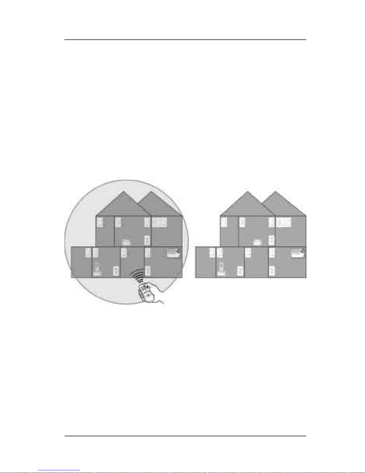
After each of your InTouch Wireless Control devices has
been wired in place or plugged into an electrical outlet,
you need to link them together into “your” network.
This makes sure that no device has been left out. It also
ensures that, should your neighbors also have Z-Wave
systems, no outside controllers can operate your
network.
Usually, the electrician who wired your system will have
set up the network. If not, you can do it yourself. The
basic procedure is simple.
This section also provides instructions for removing a
device from your network—something you need to do if
you replace an old device with a new one.
Your InTouch network exists around the Hand-Held
(Model CA5500R) and its Base (Model CA5500B), which
is also the hub of the network.
Page 7
Setting Up Your Network 7
Providing a brighter solution.™
Hardware Overview
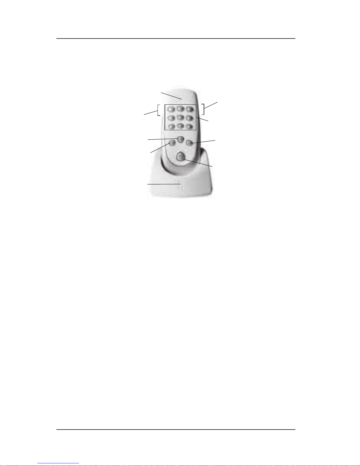
The Hand-Held and Base are the most important parts of
an InTouch network.
Status Light — provides important feedback and
conrmation when programming the network.
The <Include> and <Exclude> Buttons — located on
the side or edge of the Hand-Held, are used during
programming to add or remove devices as part of the
InTouch network.
<Scene Selection> Buttons — used to select a scene that
has been programmed into the network for activation.
The <Enter> Button — used to activate a scene that is
programmed into the network.
The <Raise> and <Lower> Buttons — used to raise and
lower levels of devices (e.g., dimmer switches) that are
part of selected scenes.
The <Home Button> — has special uses explained in this
guide.
The Power Light — tells the power status of the Base: it
pulses blue when charging the Hand-Held, lights solid
blue when the Hand-Held is fully charged, lights dim
blue when the Hand-Held is not in the Base, and blinks
red when the Hand-Held cannot be charged.
<EXCLUDE>
button
(on left side)
The
<ENTER>
button
Press to
<RAISE>
levels
<INCLUDE>
button
(on right side)
Press to
<LOWER>
levels
<SCENE SELECTION>
buttons
The <HOME> button
has special uses
explained in
this guide
The STATUS LIGHT
The
POWER LIGHT
<EXCLUDE>
button
(on left side)
The
<ENTER>
button
Press to
<RAISE>
levels
<INCLUDE>
button
(on right side)
Press to
<LOWER>
levels
<SCENE SELECTION>
buttons
The <HOME> button
has special uses
explained in
this guide
The STATUS LIGHT
The
POWER LIGHT
Page 8

8 InTouch™ User Guide
Copyright © 2006 Intermatic, Inc.
Locating a Lost Hand-Held
If the Hand-Held is misplaced (separated from its Base),
here’s how to locate it:
Disconnect the Base from the power supply (pull its
plug), then plug it back in. Within about 15 minutes,
when the Base “nds” the Hand-Held, the HandHeld will beep and ash.
Press any button on the Hand-Held to stop the
beeping and ashing.
NOTE: If for any reason power is interrupted to the
base, the Hand-Held may begin ashing and beeping
even though it is not lost.
Before You Begin…
Your InTouch system should be set up “from scratch”
when installation is complete. If any prior programming
exists in any controller(s) or other devices — if any of
the devices were ever used before — your system may
not operate as efciently or predictably as it should.
This might have happened, for example, if the installer
ran some preliminary programming tests on a few
devices of his own, which are not part of your system.
NOTE: This is extremely important! If you are ever
unsure about a device, reset it completely. Using
devices that have not been reset can corrupt the
network information in all your controllers, causing
you to have to completely reset and re-setup every
device in your network.
NOTE: When InTouch devices are initially powered
up, their status indicators will blink blue and/or
red to indicate they are ready to be included into a
network.
Run the following reset procedure to completely
wipe your system clean. Then, when you are sure
about the state of your system, you can proceed with
programming it with the devices that make up your
network.
1.
2.
Page 9

Setting Up Your Network 9
Providing a brighter solution.™
NOTE: The battery pack is initially unplugged to
preserve battery life. Remove the battery cover and
plug in the battery. Replace the battery cover. The
Hand-Held must have its battery installed and be
properly charged before being used. Place the remote
in the Base. The Power light on the Base will pulse
blue when charging, then change to solid blue when
the Hand-Held is fully charged and ready to use.
Place the Hand-Held in the Base and make sure it is
powered ON.
While the Hand-Held is in the Base, press and hold
simultaneously the <RAISE> and <LOWER> buttons
until the Power Light on the Base lights up with a
pink color.
Wait for the pink light to go off.
Reset controllers as follows:
NOTE: Unless resetting the entire system, controllers
should not be reset. Instead, simply remove them
from the network. See page 16.
HAND-HELD CONTROLLER—
Press and hold simultaneously the <5>,
<ENTER> and <HOME> buttons until the Status
Light on the Hand-Held lights up with a pink
color.
Wait for the pink light to go off.
IN-WALL SCENE/GROUP CONTROLLER—
Press and hold
simultaneously the <6>,
<ENTER> and <HOME>
buttons until the Status
Light on the Hand-Held
lights up with a pink
color.
Wait for the pink light to go off.
1.
2.
3.
4.
a.
b.
a.
b.
<HOME>
button
STATUS
LIGHT
<HOME>
button
STATUS
LIGHT
Page 10
10 InTouch™ User Guide
Copyright © 2006 Intermatic, Inc.
MASTER IN-WALL CONTROLLER—
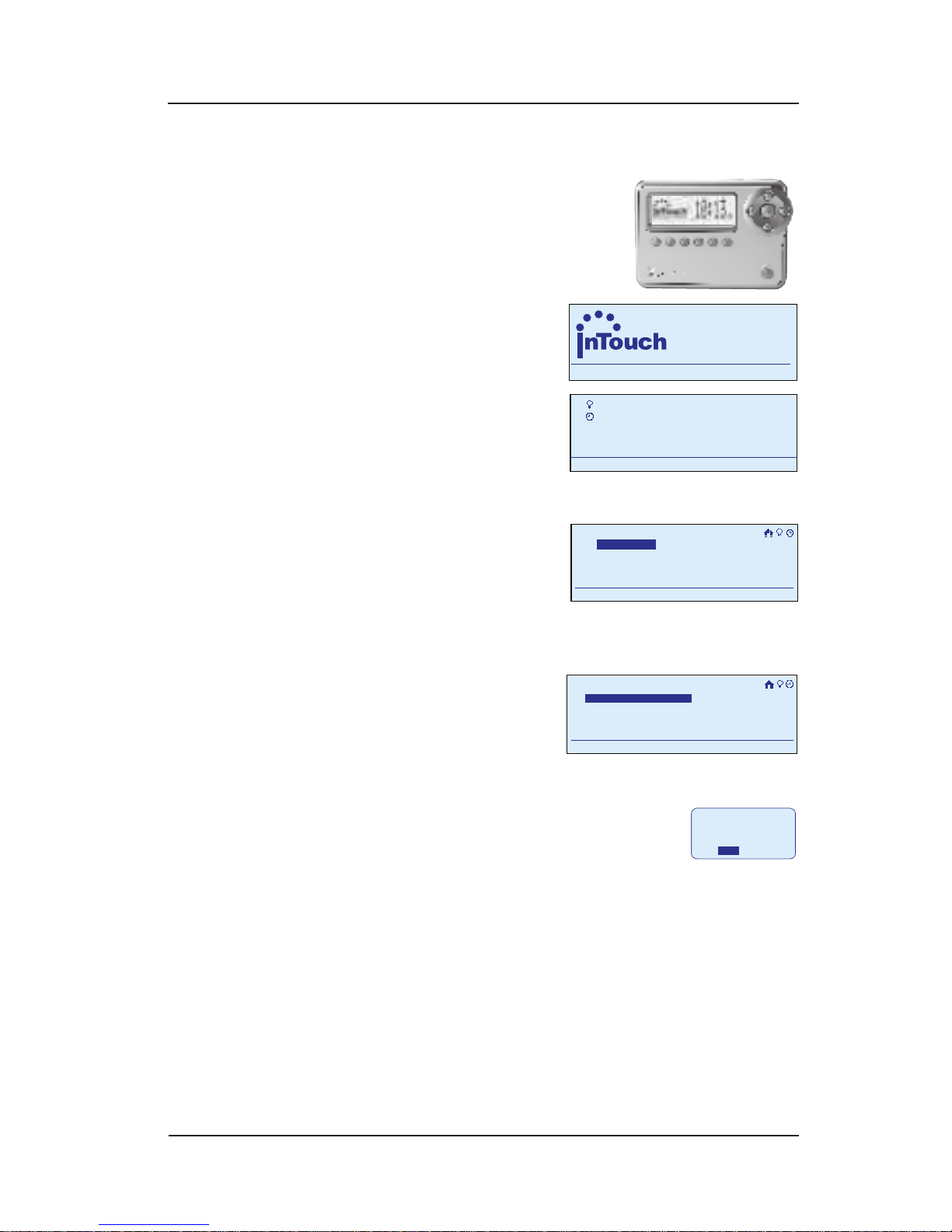
Use the <ARROW> buttons
to navigate through the
following routine. See page
37 for Hardware Overview.
Begin at the InTouch
Home Screen as
shown.
Press the
<ENTER> button.
The screen
displays the
Main Menu as shown.
Scroll with the
<UP/DOWN>
arrows to select
Setup, then
press <ENTER>. The screen displays system
setup options.
Select Setup
Network, then
press <ENTER>.
The screen
displays options for setting up the network.
Select Reset Controller, then
press <ENTER>. The system
will ask for conrmation.
Press the <RIGHT> arrow button to select
YES, then press <ENTER>. The screen
will display “Reset to Factory Defaults”
when the reset procedure is completed
internally.
Repeat this procedure for each controller in your
network.
When you have completed this reset procedure, you can
proceed with setting up your InTouch network.
a.
a.
a.
a.
b.
a
WIRELESS CONTROLS
TM
11:25
a
WIRELESS CONTROLS
TM
11:25
My Scenes
My Events
Setup
11:25a
My Scenes
My Events
Setup
11:25a
Setup Home
Set Time
Setup
11:25a
Setup Network
Setup Home
Set Time
Setup
11:25a
Setup Network
Setup>Setup Network
Include Node
11:25a
Exclude Node
Replicate Receive
Reset Controller
Setup>Setup Network
Include Node
11:25a
Exclude Node
Replicate Receive
Reset Controller
Are you sure you
want to reset?
Data will be
Lost.
NO YES
Are you sure you
want to reset?
Data will be
Lost.
NO YES
Page 11

Setting Up Your Network 11
Providing a brighter solution.™
Creating the Network
Use this procedure to create the network of your
InTouch devices.
If you “include” ALL the devices in your network before
you create scenes, your network will operate smoother,
more responsively, and with maximum efciency.
You need the Hand-Held (Model CA5500R) with Base
(Model CA5500B) to complete this procedure.
NOTE: For maximum network performance, locate
the Base in a central area of the house.
Linking the Hand-Held to the Base
Your InTouch network consists of the private
connections between your Hand-Held, its Base (which
is actually the “brains” of the system as well as the
charger for the Hand-Held), and all of the devices your
network controls.
Before linking to devices throughout the house, you
must link the Hand-Held to its Base. If you have more
than one Hand-Held, you must link each of them to
their respective bases. This makes sure that only your
Hand-Held(s) will be able to control the devices in
your network. If neighbors have InTouch systems, their
controllers will not be able to affect your network.
Page 12
12 InTouch™ User Guide
Copyright © 2006 Intermatic, Inc.
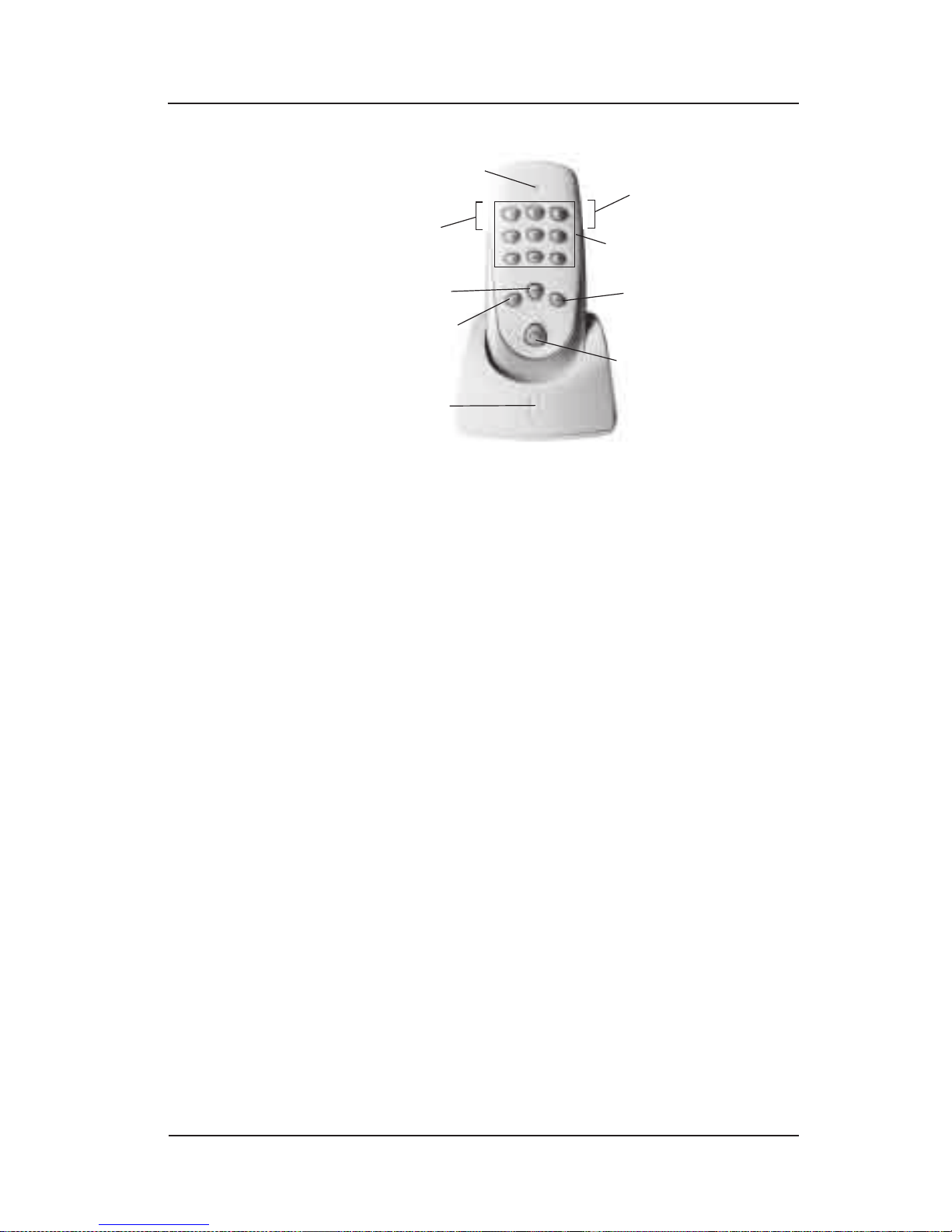
Place the Hand-Held in the Base and make sure the
Base is powered ON.
Press and release the <INCLUDE> button on the HandHeld so that its Status Light lights up blue, indicating
that it is in Include mode.
Wait for the Status Light on the Hand-Held to go out.
When it does, the link is successful. The Status Light
on the Hand-Held will:
Blink BLUE once if programming is successful.
Blink RED once if programming failed. If this
happens, reset Base and Remote and try again.
See page 9. If it fails a second time, refer to
the Troubleshooting Section of this Manual for
additional information.
NOTE: If you ever lose or damage your Hand-Held, you
can order a replacement and easily transfer over any
program existing on the old controller. Just follow the
procedure above: place the new Hand-Held in the Base
and press the <INCLUDE> button.
1.
2.
3.
•
•
<EXCLUDE>
button
(on left side)
The
<ENTER>
button
Press to
<RAISE>
levels
<INCLUDE>
button
(on right side)
Press to
<LOWER>
levels
<SCENE SELECTION>
buttons
The <HOME> button
has special uses
explained in
this guide
The STATUS LIGHT
The
POWER LIGHT
<EXCLUDE>
button
(on left side)
The
<ENTER>
button
Press to
<RAISE>
levels
<INCLUDE>
button
(on right side)
Press to
<LOWER>
levels
<SCENE SELECTION>
buttons
The <HOME> button
has special uses
explained in
this guide
The STATUS LIGHT
The
POWER LIGHT
Page 13

Setting Up Your Network 13
Providing a brighter solution.™
Linking an Additional Base and Hand-Held
to the Network
If you have an additional Base and Hand-Held, use the
following procedure to link them to the network.
NOTE: The original Base and Hand-Held must already
be included in the network before you can proceed.
Place the new Hand-Held in the new Base. (Make
sure it’s powered ON.)
Take the original Hand-Held out of its base and press
and release the <INCLUDE> button so that its Status
Light lights up blue, indicating that it is in Include
mode.
Press and hold (for 4+ seconds) the <HOME> button
on the new Hand-Held. When the linking process is
complete, the Status Light on the original Hand-Held
will:
Blink BLUE once if programming is successful.
Blink RED once if programming failed. If this
happens, try again. If it fails a second time, refer
to the Troubleshooting Section of this Manual for
additional information.
While the new Hand-Held is still in its new Base,
press the <INCLUDE> button so that its Status Light
lights up blue, indicating that it is in Include mode.
Wait for the Status Light on the new Hand-Held to:
Blink BLUE once if programming is successful.
Blink RED once if programming failed. If this
happens, try again. If it fails a second time, refer
to the Troubleshooting Section of this Manual for
additional information.
1.
2.
3.
•
•
1.
2.
•
•
Page 14
14 InTouch™ User Guide
Copyright © 2006 Intermatic, Inc.
Adding Devices to the Network
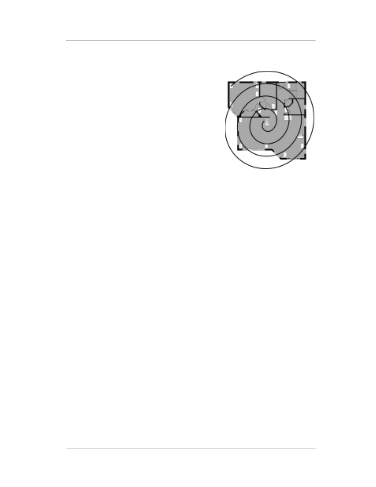
When including devices,
work in ever-widening
circles away from the
centrally-located Base.
Remove the Hand-Held
from the Base and take it
to the rst device to be
included in the network.
Hold the Hand-Held
within a few feet of the
device to be included.
Make sure the lights under the Hand-Held’s buttons
are lit. If they are not lit, press any button to wake
the Hand-Held from battery-saving sleep mode.
Perform the following procedure and repeat for each
device to be included:
Press and release the <INCLUDE> button on the
Hand-Held. The Status Light lights up blue,
indicating that it is in Include mode.
NOTE: If the Hand-Held Status light blinks
RED immediately upon pressing the <INCLUDE>
button then the Base and Remote have not
been properly linked together. If this happens,
reset Base and Remote and try again. See
page 9.
Press the <ACTIVATION> button on the device to be
included. The Status Light on the Hand-Held will
blink off briey when it has received the device
being added. When nished, the Status Light on
the Hand-Held will:
Blink BLUE once if the procedure is
successful.
Blink RED once if the procedure failed. If this
happens, try again. If it fails a second time,
refer to the Troubleshooting Section of this
Manual for additional information.
1.
2.
3.
4.
a.
a.
-
-
Page 15
Setting Up Your Network 15
Providing a brighter solution.™
NOTE: On InTouch devices that have this feature,
the status light will stop blinking BLUE and/or RED
to indicate that the device has been added to the
network.
Additional Considerations:
If the device doesn’t have a button (for example,
a simple on-off switch), press the rocker switch
on the device.
If the device is the In-Wall
Scene/Group Controller,
press and hold (for 4+
seconds) the <HOME> button
on the device. The Status
Light on the Hand-Held will:
Blink BLUE once if the
procedure is successful.
Blink RED once if the procedure failed. If this
happens, the In-Wall Scene/Group Controller
must be EXCLUDED and then RE-INCLUDED to the
network.
If the device is the In-Wall Master Controller:
NOTE: It is best to add this device to the network
last.
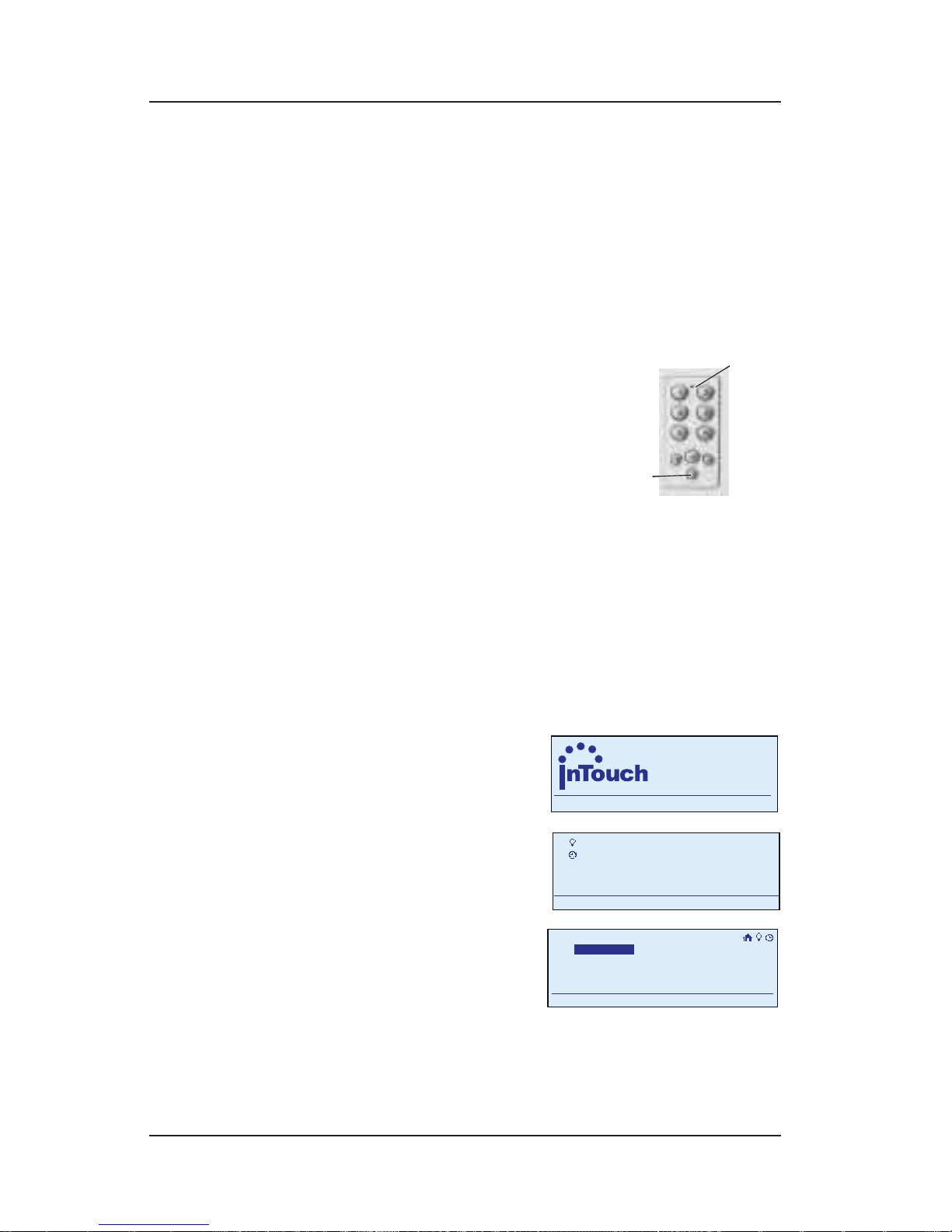
Begin at the InTouch
Home Screen as
shown.
Press <ENTER>. The
screen displays the
Main Menu.
Scroll with the
<UP/DOWN>
arrows to select
Setup, then press
<ENTER>. The
screen displays system setup options.
•
•
-
-
•
a.
b.
<HOME>
button
STATUS
LIGHT
<HOME>
button
STATUS
LIGHT
a
WIRELESS CONTROLS
TM
11:25
a
WIRELESS CONTROLS
TM
11:25
My Scenes
My Events
Setup
11:25a
My Scenes
My Events
Setup
11:25a
Setup Home
Set Time
Setup
11:25a
Setup Network
Setup Home
Set Time
Setup
11:25a
Setup Network
Page 16

16 InTouch™ User Guide
Copyright © 2006 Intermatic, Inc.
Select Setup
Network, then
press <ENTER>. The
screen displays
options for setting up the network.
Select Replicate Receive, then press <ENTER>.
The screen will display as follows:
“Waiting for routing table update…” when
the Replicate Receive command has been
received.
“Loading routing table…” when the Master
Controller is communicating with the
Base/Hand-Held.
“Routing table updated” if the update was
successful.
“Routing table update failed” if the
update was not successful. Refer to the
Troubleshooting Section of this Manual for
additional information.
After a brief delay (up to 30 seconds) the
screen returns to the InTouch Home Screen.
Repeat this simple procedure for each device in your
network, working in widening circles from the Base.
When you’ve included each device, you’re done.
Follow the same procedure to include other Z-Wave devices
in the network (i.e., Intermatic HomeSettings™ devices or
devices from other manufacturers). For specic information
on which button to press, refer to the user guide that came
with the device or contact the manufacturer.
Removing Devices from the Network
Use this procedure to remove InTouch devices from
your home network. Before you replace an old device
with a new one, you need to make sure your network
isn’t still looking for it.
NOTE: If you are unsure if a device has been used
before, it is always a good idea to “remove” it rst.
c.
d.
-
-
-
-
6.
Setup>Setup Network
Include Node
11:25a
Exclude Node
Replicate Receive
Reset Controller
Setup>Setup Network
Include Node
11:25a
Exclude Node
Replicate Receive
Reset Controller
Page 17

Setting Up Your Network 17
Providing a brighter solution.™
Remove the Hand-Held from the Base and take it to
the rst device to be removed in the network.
Hold the Hand-Held within a few feet of the device
to be removed.
Make sure the lights under the Hand-Held’s buttons
are lit. If they are not lit, press any button to wake
the Hand-Held from battery-saving sleep mode.
Perform the following procedure and repeat for each
device to be included:
Press and release the <EXCLUDE> button on
the Hand-Held. The Status Light lights up red,
indicating that it is in Exclude mode.
Press the <ACTIVATION> button on the device to be
excluded.
NOTE: On InTouch devices that have this feature,
the status light will begin blinking BLUE and/or RED
to indicate that the device is ready to be removed
from the network.
Additional Considerations:
If the device doesn’t have a button (for example,
an on-off switch), press the rocker switch on the
device.
If the device is the In-Wall
Scene/Group Controller
(Model CA5000), press
and hold (for 4+ seconds)
the <HOME> button on the
device. The Status Light on
the Hand-Held will:
Blink BLUE once if programming is successful.
Blink RED once if programming failed. If this
happens, try again. If it fails a second time,
refer to the Troubleshooting Section of this
Manual for additional information.
1.
2.
3.
4.
a.
b.
•
•
-
-
<HOME>
button
STATUS
LIGHT
<HOME>
button
STATUS
LIGHT
Page 18
18 InTouch™ User Guide
Copyright © 2006 Intermatic, Inc.
If the device is the InWall Master Controller,
use the <ARROW> buttons
to navigate through the
following routine.
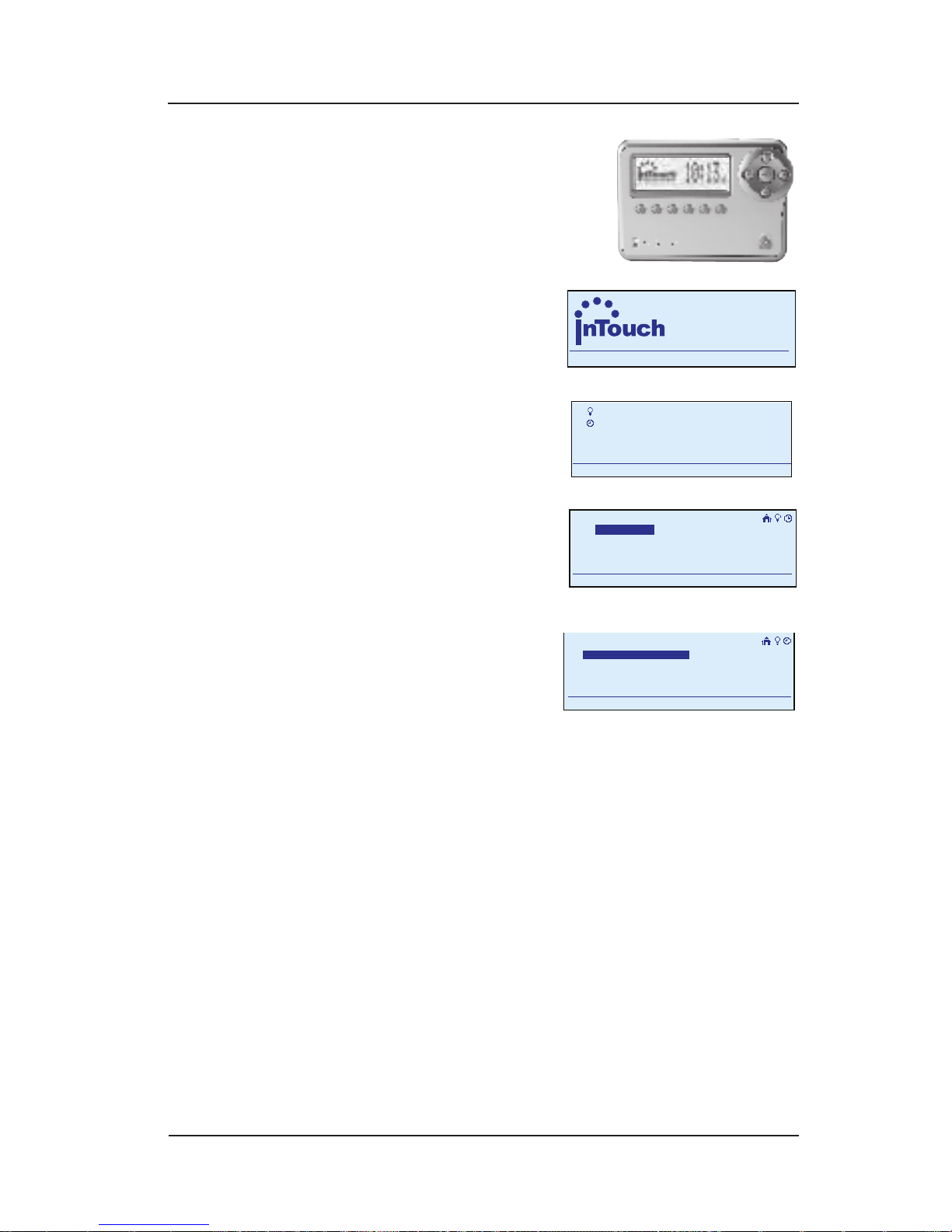
Begin at the InTouch
Home Screen as
shown.
Press the <ENTER>
button. The screen
displays the Main
Menu as shown.
Scroll with the <UP/
DOWN> arrows to
select Setup, then
press <ENTER>. The
screen displays system setup options.
Select Setup
Network, then
press <ENTER>. The
screen displays
options for setting up the network.
Select Replicate Receive, then press <ENTER>.
The screen will display as follows:
“Waiting for routing table update…” when
the Replicate Receive command has been
received and <ENTER> is pressed.
“Loading routing table…” when the Master
Controller is communicating with the
Base/Hand-Held.
“Routing table updated” if the update was
successful.
“Routing table update failed” if the
update was not successful. Refer to the
•
a.
a.
a.
b.
•
•
•
•
a
WIRELESS CONTROLS
TM
11:25
a
WIRELESS CONTROLS
TM
11:25
My Scenes
My Events
Setup
11:25a
My Scenes
My Events
Setup
11:25a
Setup Home
Set Time
Setup
11:25a
Setup Network
Setup Home
Set Time
Setup
11:25a
Setup Network
Setup>Setup Network
Include Node
11:25a
Exclude Node
Replicate Receive
Reset Controller
Setup>Setup Network
Include Node
11:25a
Exclude Node
Replicate Receive
Reset Controller
Page 19

Programming Scenes with Controllers 19
Providing a brighter solution.™
Troubleshooting Section of this Manual for
additional information.
After a brief delay (up to 30 seconds) the
screen returns to the InTouch Home Screen.
Repeat this procedure for each device you want to
remove from your network.
Follow the same procedure to remove other Z-Wave
devices in the network (i.e., Intermatic HomeSettings
devices or devices from other manufacturers). For
specic information on which button to press, refer to
the user guide that came with the device or contact the
manufacturer.
4.
Page 20
20 InTouch™ User Guide
Copyright © 2006 Intermatic, Inc.
Section 2:
Programming Scenes with
Controllers
Overview
Scenes are the heart and soul of an InTouch network.
A scene is a group of devices that have been set to
respond the way you want — typically for accented
mood lighting or security. For example, if you set up
the lighting in your living room a certain way for
watching a movie on your big screen TV, you’ve
created a scene. Another scene might be to turn on
all the lights on your stairway and upstairs hallway.
Or your porch light, the lights in your yard, and the
light at the end of your driveway.
Without scenes, your controllers would provide you
with far less remote control capability.
With scenes, you can control whole groups of items
in a totally customized, virtually unlimited manner.
The Hand-Held (Model CA5500R) with Base (Model
CA5500B) is the mandatory controller for an InTouch
wireless network (the Base is the brains of your network).
You can also create and manage scenes with other
optional controllers, including:
•
•
Page 21

Programming Scenes with Controllers 21
Providing a brighter solution.™
The In-Wall Master Controller (Model CA7100)
The In-Wall Scene/Group Controller (Model
CA5000)
This section provides instructions for the Hand-Held and
the In-Wall Scene/Group Controller Controller.
NOTE: If your system includes an In-Wall Master
Controller, it may be easier to program scenes using
that device rather than the routines described below.
Refer to instructions for the In-Wall Master Controller in
Sections 4 and 5.
After you have created scenes throughout your home
with these devices, you use them to operate the network
by activating the scenes you have set up.
Strategy for Setting Up Scenes
An In-Wall Scene/Group Controller can give you
maximum control within a single room. For example, in
place of a light switch in your living room, its six buttons
could control the room’s accent lighting, changing
between different scenes: watching TV, socializing,
reading, all on full for cleaning up, turning on a ceiling
fan, etc.
If you have an In-Wall Scene/Group Controller in each
room of a house, you would program its buttons to
control the scenes in that room. And, you might reserve
the top left button on all room controllers as the “full on
alert” button that turns on the whole house.
By contrast, you might program the Hand-Held for full
on/off capability for each room — so it’s easy to make
sure the lights are all off.
Or, the top left button turns off that pesky light that’s
always being left on upstairs. The possibilities are
endless!
And if someone manually turns some lights in the family
room ON but some are still OFF, when you press the
“Family Room” button on the Hand-Held, it will turn all
the lights ON. That’s because when elements in a scene
have been separately activated, the system rst turns
•
•
Page 22
22 InTouch™ User Guide
Copyright © 2006 Intermatic, Inc.
all the elements on to “harmonize” the scene. Press the
button again and all elements of the scene will turn off.
Creating a Scene
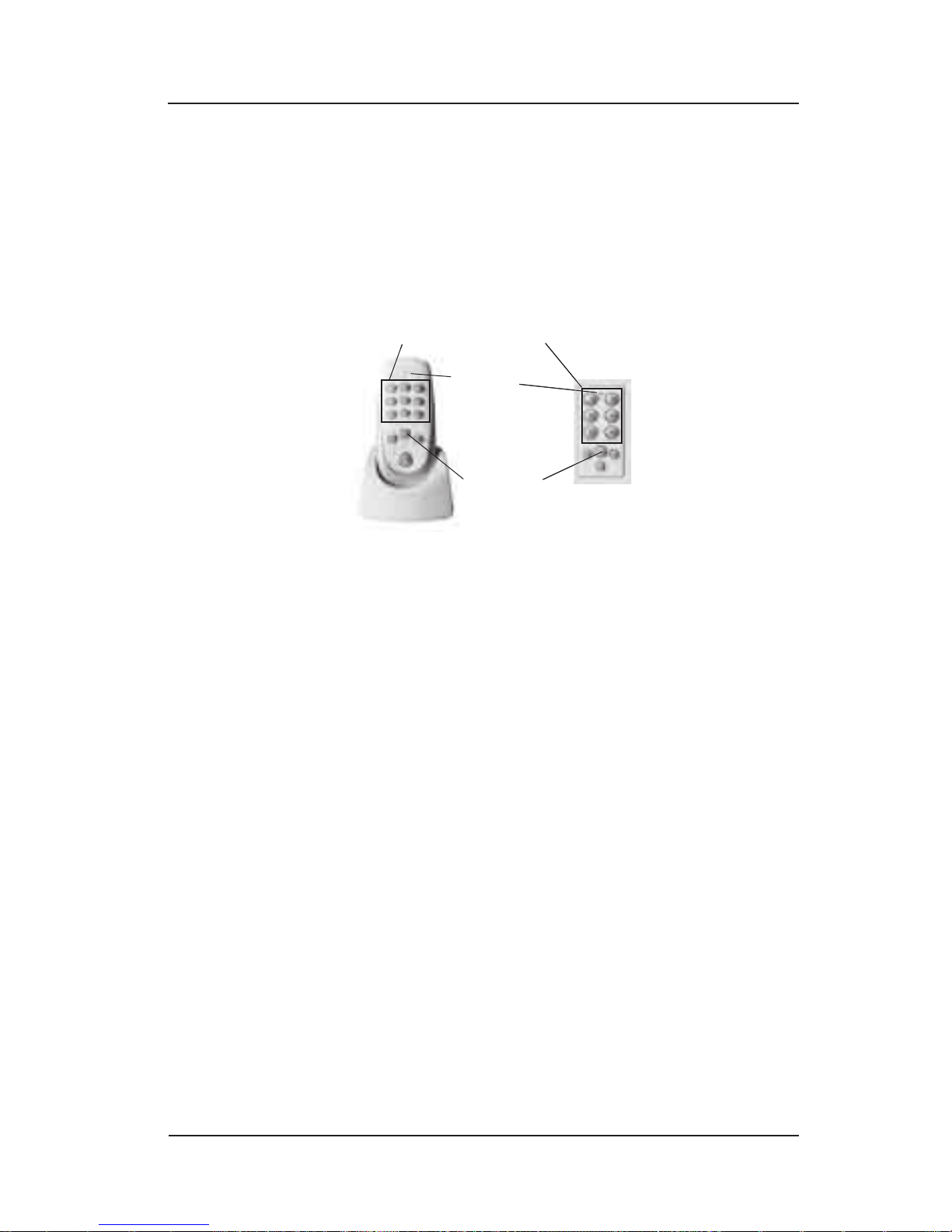
Use one or more of the controllers shown here to
program scenes to be activated by specic buttons on
the controller(s).
If using a Hand-Held, make sure the lights under the
Hand-Held’s buttons are lit. If they are not lit, press
any button to wake the Hand-Held from batterysaving sleep mode.
Press and hold (for approximately 10 seconds) the
<SCENE SELECTION> button you want to control the
scene. The Status Light on the device will pulse
once slowly with a blue light. This indicates that the
button is in “learning” mode.
NOTE: Scene “learning” mode will time-out after
5 minutes from the last button press and save the
scene.
Go around your home and make a change in the
status of each device you want to include in the
scene. For example, turn a room light on or off, set a
dimmer to a desired level, etc. To include an InTouch
electric outlet (e.g., where you have plugged in a
lamp), press the button on the outlet.
To include other Z-Wave devices in the scene (i.e.,
Intermatic HomeSettings devices or other brands),
turn them ON or OFF from their existing state. The
system will turn them back to their original state
1.
2.
3.
<ENTER>
button
STATUS
LIGHT
<SCENE SELECTION> buttons
Hand-Held with Base In-Wall Scene/Group Controller
<ENTER>
button
STATUS
LIGHT
<SCENE SELECTION> buttons
Hand-Held with Base In-Wall Scene/Group Controller
Page 23

Programming Scenes with Controllers 23
Providing a brighter solution.™
when it “sees” them. This may take a few minutes as
the network sorts things out. When it’s nished, set
the device as you want it for the scene.
Return to the controller. Press and hold (for
approximately 10 seconds) the button being
programmed. The Status Light will stay on while the
controller is gathering information, and will then:
Blink BLUE once if programming is successful.
Blink RED once if programming failed. If this
happens, try again. If it fails a second time, refer
to the Troubleshooting Section of this Manual for
additional information.
Test the programming. Press the <SCENE SELECTION>
button once to select the scene, then press the
<ENTER> button to activate the scene. Press <ENTER>
again to deactivate.
NOTE: If all of the devices in the scene are on, the
<SCENE SELECTION> button will be brightly lit. This
indicates that the status of the selected scene is ON.
That’s all there is to it. Repeat the procedure to program
other buttons on the controller to create other scenes.
Activating a Scene
Once you’ve set up a scene by programming it with
your controller, use this procedure to activate it.
If using a Hand-Held, make sure the lights under the
Hand-Held’s buttons are lit. If they are not lit, press
any button to wake the Hand-Held from batterysaving sleep mode.
Press the <SCENE SELECTION> button that controls the
scene. The ring around the button will begin to pulse
with a blue light.
NOTE: More than one <SCENE SELECTION> button can
be pressed to adjust several scenes at the same time.
If you want to deselect all the scenes selected before
making changes, press the <HOME> button on the
controller.
4.
•
•
5.
1.
2.
Page 24

24 InTouch™ User Guide
Copyright © 2006 Intermatic, Inc.
Now activate the scene by pressing the <ENTER>
button to turn the scene ON or OFF.
Press the <SCENE SELECTION> button again to deselect
it or the <HOME> button to deselect a group of scenes.
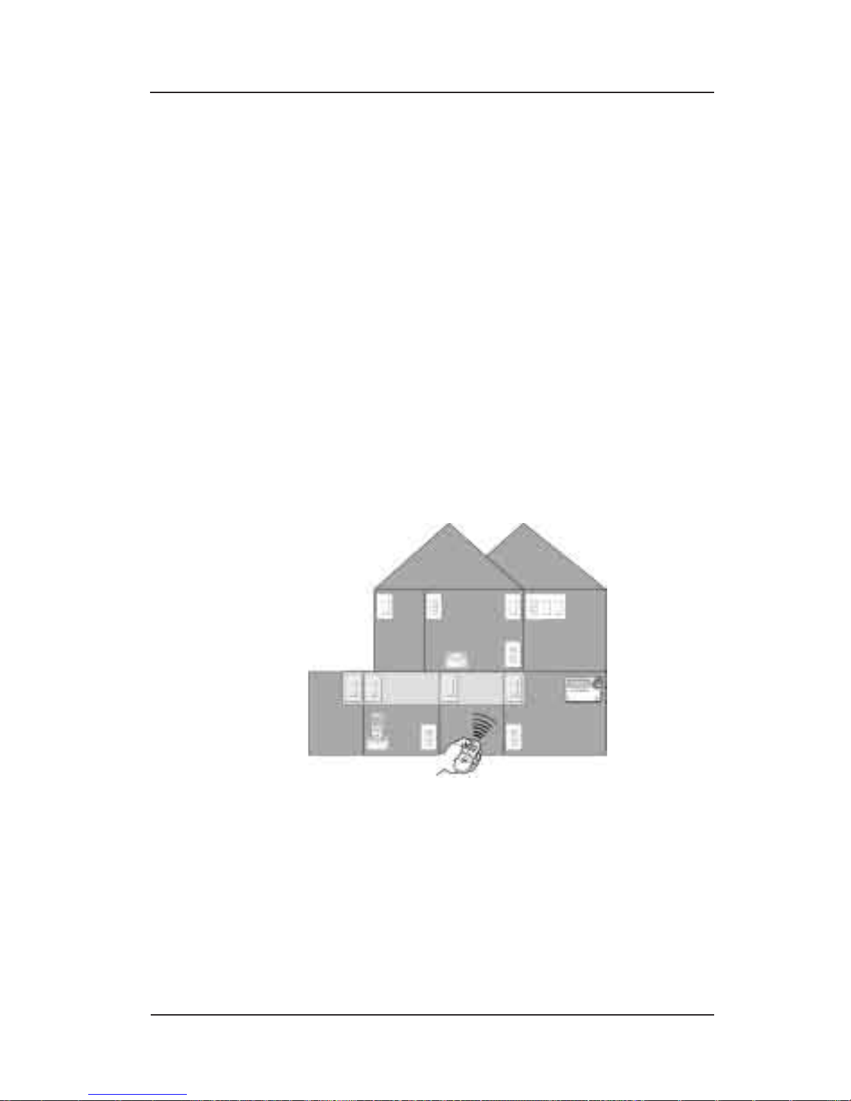
You can activate the scene from anywhere in your
house, and from at least 50 feet from any device in the
network.
Also, when a scene is ON, the light around its button
is on — so if you have a scene that controls the lights
in the kids’ room, you’ll know whether lights were left
on just by looking at the button that controls the scene.
This is great for saving trips upstairs to check, out to the
garage, etc.
Copying a Scene to Another InTouch Controller
What if you have more than one InTouch controller
and want each controller to be able to control a scene
you’ve already created?
You can copy the scene from one InTouch controller to
another.
If using a Hand-Held, make sure the lights under the
Hand-Held’s buttons are lit. If they are not lit, press
any button to wake the Hand-Held from batterysaving sleep mode.
Press and hold (for approximately 10 seconds) the
<SCENE SELECTION> button on the controller you want
to “learn” the scene you have already programmed
on another controller. The Status Light on the
“learning” controller will pulse once with a blue
light.
On the other InTouch controller, press the <SCENE
SELECTION> button that activates the scene you want
to attach or copy. You can press more than one
<SCENE SELECTION> button on more than one device
to combine several scenes.
NOTE: The scene(s) will activate when you perform
this step. Ignore the activation and continue.
3.
4.
1.
2.
3.
Page 25

Programming Scenes with Controllers 25
Providing a brighter solution.™
NOTE: If you want, you can make changes to the
scene as it will be controlled by the new controller.
If you want to do so, make them now. Any changes
you make will NOT affect the original controller.
Return to the “learning” controller. Press and hold
(for approximately 10 seconds) the button being
programmed. The Status Light will pulse once again,
and will:
Blink BLUE once if programming is successful.
Blink RED once if programming failed. If this
happens, try again. Refer to the Troubleshooting
Section of this Manual for additional information.
Test the programming. Press the <SCENE SELECTION>
button once to select the scene, then press the
<ENTER> button to activate the scene. Press <ENTER>
again to deactivate.
Making Temporary Adjustments to a Scene
Once you’ve created a scene involving dimmers, blind
controls, thermostats, etc., you may want to temporarily
adjust the settings on these devices, raising or lowering
them. Use this procedure to adjust all the devices at once.
NOTE: If you want to make a permanent adjustment,
you need to create a new scene following instructions
in Creating Scenes on page 22. If you have the In-Wall
Master Controller, you can make permanent adjustments
by editing the scene. Refer to Sections 4 and 5.
If using a Hand-Held, make sure the lights under the
Hand-Held’s buttons are lit. If they are not lit, press
any button to wake the Hand-Held from batterysaving sleep mode.
Press the <SCENE SELECTION> button that controls the
scene you want to adjust. The ring around the button
will begin to pulse with a blue light.
You now have two options for adjusting the scene:
Press and hold the <RAISE> button to raise the level.
Press and hold the <LOWER> button to lower the level.
4.
•
•
5.
1.
2.
3.
•
•
Page 26
26 InTouch™ User Guide
Copyright © 2006 Intermatic, Inc.
Release the <RAISE/LOWER> button when you’re
satised with the levels.
Press the <SCENE SELECTION> button again to deselect
it or the <HOME> button to deselect a group of scenes.
The next time you turn on the scene, the lights in the
scene will return to their originally programmed levels.
NOTE: Devices that cannot be dimmed will not respond
to the <RAISE/LOWER> adjustment.
Adding a New Device to a Scene
If you would like to add another device to an existing
scene, you must recreate the scene from the beginning,
and include the new device in the programming.
If you have the In-Wall Master Controller (Model
CA7100), you can add your new device by editing
the scene. Refer to detailed instructions for this device
provided in Sections 4 and 5 of this guide.
Deleting a Scene
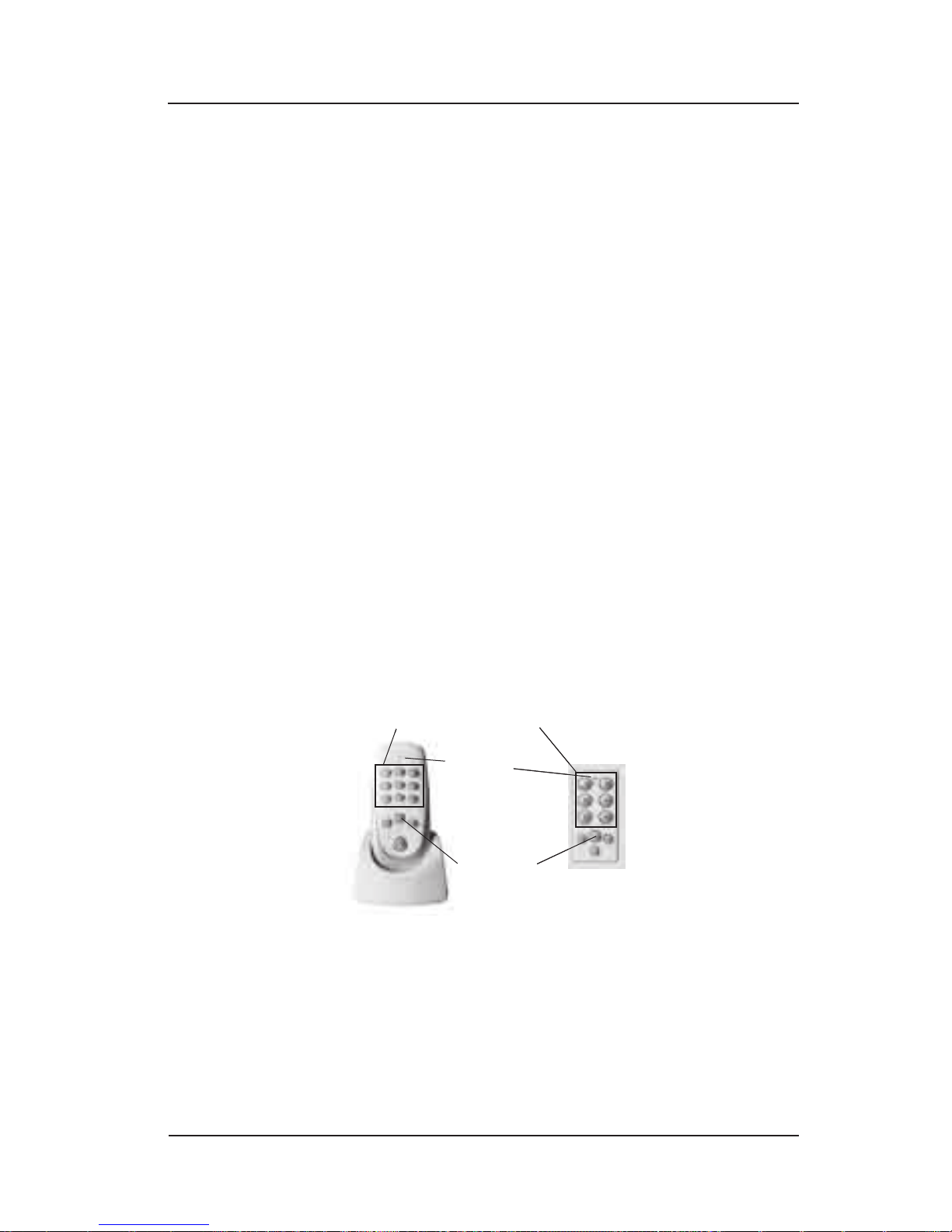
Use one or more of the controllers shown here to delete
scenes that have been created.
If using a Hand-Held, make sure the lights under the
Hand-Held’s buttons are lit. If they are not lit, press
any button to wake the Hand-Held from batterysaving sleep mode.
Press and hold (for approximately 10 seconds) the
<SCENE SELECTION> button that controls the scene you
4.
5.
1.
2.
<ENTER>
button
STATUS
LIGHT
<SCENE SELECTION> buttons
Hand-Held with Base In-Wall Scene/Group Controller
<ENTER>
button
STATUS
LIGHT
<SCENE SELECTION> buttons
Hand-Held with Base In-Wall Scene/Group Controller
Page 27

Programming Scenes with Routing Slave Devices 27
Providing a brighter solution.™
want to delete. The Status Light on the device will
pulse once slowly with a blue light. This indicates
that the button is in “learning” mode.
NOTE: At this point the scene is deleted.
Press and hold (for approximately 10 seconds)
the button that controls the scene being deleted.
The Status Light will stay on while the controller is
gathering information, and will then blink RED once
if deletion is successful.
Test the programming. Press the <SCENE SELECTION>
button once to select the scene, then press the
<ENTER> button to activate the scene. None of the
components previously associated with the scene
should respond.
If the system includes a In-Wall Master Controller,
the display panel will no longer list the scene.
NOTE: It may take up to 24 hours for the In-Wall Master
Controller to update itself to these changes and show
them on its display panel. To force a faster update,
perform another “Include” procedure with the In-Wall
Master Controller. See page 14.
3.
4.
Page 28
28 InTouch™ User Guide
Copyright © 2006 Intermatic, Inc.
Section 3:
Programming Scenes with
Routing Slave Devices
Overview
You can also do simple programming with many of the
devices installed throughout your house — like motion
sensors and programmable switches.
These devices — known technically as “routing slave”
devices — may control connected electrical loads like
lights and appliances.
However, they can also be programmed to create and
activate scenes that you can set up throughout your
house.
A scene is a group of devices that have been
programmed to respond the way you want. For
example, if you set up the lighting in your living
room a certain way for watching a movie on your big
screen TV, you’ve created a scene. Another scene
might be to turn on all the lights on your stairway
and upstairs hallway. Or your porch light, the lights
in your yard, and the light at the end of your
driveway.
Page 29
Programming Scenes with Routing Slave Devices 29
Providing a brighter solution.™
Creating a Scene
With your network based on the Hand-Held (Model
CA5500R) with Base (Model CA5500B), follow this
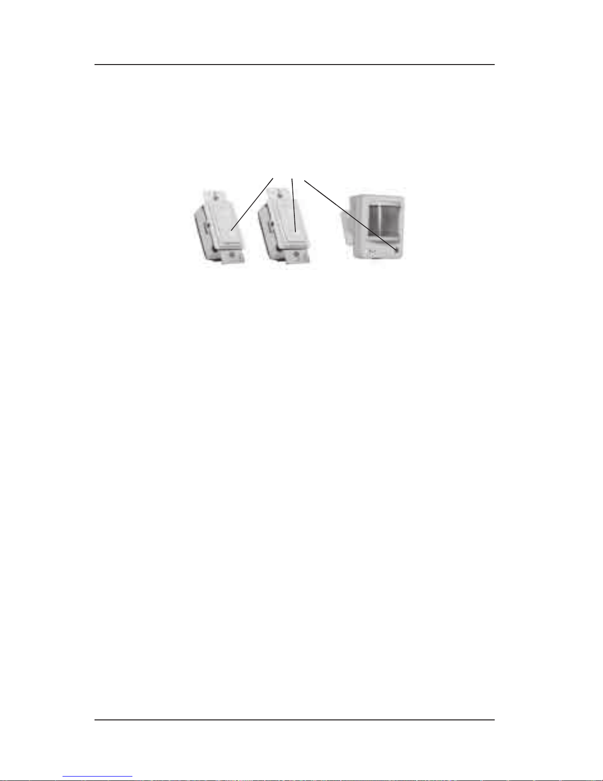
procedure to create a scene with the following devices:
NOTE: When activating one of these devices manually, all
the devices controlled by the scene will be activated.
Depending on which device you want to program,
perform the following step:
Motion Sensor—Press and hold (for
approximately 10 seconds) the <ACTIVATION>
button.
Switch-Type Devices—Make sure the device
is in OFF mode, then press and hold (for
approximately 10 seconds) the lower portion of
the rocker switch.
The Status Light will pulse once with a blue light,
indicating that the device is in “learning” mode.
Go around your home and make a change in the
status of each device you want to include in the
scene. For example, turn a room light on or off, set a
dimmer to a desired level, etc. To include an InTouch
electric outlet (e.g., where you have plugged in a
lamp), press the button on the outlet.
To include other Z-Wave devices in the scene (i.e.,
Intermatic HomeSettings devices or other brands),
turn them ON or OFF from their existing state. The
system will turn them back to their original state
when it “sees” them. This may take a few minutes as
the network sorts things out. When it’s nished, set
the device as you want it for the scene.
1.
•
•
2.
<ACTIVATION>
button
Motion Sensor
Switch-Type Devices
<ACTIVATION>
button
Motion Sensor
Switch-Type Devices
Page 30

30 InTouch™ User Guide
Copyright © 2006 Intermatic, Inc.
When nished, return to the device you are programming and press once and hold (for approximately 10
seconds):
Motion Sensor—The <ACTIVATION> button.
Switch-Type Devices—The lower portion of the
rocker switch.
The Status Light will stay on while the device is
gathering information, and will then:
Blink BLUE once if programming is successful.
Blink RED once if programming failed. If this
happens, try again. Refer to the Troubleshooting
Section of this Manual for additional information.
Test the programming. Press the <ACTIVATION> button
once to activate the scene (or walk in front of the
motion detector), then again to deactivate.
Attaching an Existing Scene to a Device
You can attach (or copy) an existing scene—one already
programmed to a button on your Hand-Held or other
InTouch controller—to a switch-type device, or motion
sensor, using the device as an alternate way of activating
the scene.
NOTE: You must have an InTouch Base (Model
CA5500B) for this procedure to work.
Depending on which device you want to program,
perform the following step:
Motion Sensor—Press and hold (for
approximately 10 seconds) the <ACTIVATION>
button.
Switch-Type Device—Make sure the device
is in OFF mode, then press and hold (for
approximately 10 seconds) the lower portion of
the rocker switch.
The Status Light will pulse once with a blue light,
indicating that the device is in “learning” mode.
3.
•
•
•
•
4.
1.
•
•
Page 31

Programming Scenes with Routing Slave Devices 31
Providing a brighter solution.™
On the controller, press the <SCENE SELECTION> button
that activates the scene you want to attach or copy.
You can press more than one <SCENE SELECTION>
button on more than one device to combine several
scenes.
NOTE: The scene(s) will activate when you perform
this step. Ignore the activation and continue.
NOTE: If you want, you can make changes to the
scene as it will be controlled by the new device. If
you want to do so, make them now. Any changes
you make will NOT affect the original controller.
When nished, return to the device you are programming and press once and hold (for approximately 10
seconds):
Motion Sensor—The <ACTIVATION> button.
Switch-Type Devices—The lower portion of the
rocker switch.
The Status Light will stay on while the device is
gathering information, and will then:
Blink BLUE once if programming is successful.
Blink RED once if programming failed. If this
happens, try again. Refer to the Troubleshooting
Section of this Manual for additional information.
Test the programming. Press the <ACTIVATION> button
once to activate the scene, then again to deactivate.
Removing a Scene from a Device
Depending on which device you want to remove a
scene from, perform the following step:
Motion Sensor—Press and hold (for
approximately 10 seconds) the <ACTIVATION>
button.
Switch-Type Devices—Make sure the device
is in OFF mode, then press and hold (for
approximately 10 seconds) the lower portion of
the rocker switch.
2.
3.
•
•
•
•
4.
1.
•
•
Page 32

32 InTouch™ User Guide
Copyright © 2006 Intermatic, Inc.
The Status Light will pulse once with a blue light,
indicating that the device is in “learning” mode.
NOTE: At this point the scene is deleted.
Depending on which device you want to remove,
perform the following step:
Motion Sensor—Press and hold (for
approximately 10 seconds) the <ACTIVATION>
button.
Switch-Type Device—Make sure the device
is in OFF mode, then press and hold (for
approximately 10 seconds) the lower portion of
the rocker switch.
The Status Light will stay on while the device is
gathering information, and will then blink RED once
if deletion is successful.
Your previous scene is deleted and—since you
added no new devices—there is no new scene.
Combining InTouch Devices with Other
Manufacturers
Programming a non-InTouch Routing
Slave Device in an InTouch Network
Routing slave devices from other Z-Wave systems (i.e.,
Intermatic HomeSettings devices or other brands) can
be programmed to function in the network. A good
example of this is a motion sensor. Use the following
procedure to program the routing slave device for the
network.
NOTE: During the programming procedure that follows,
the InTouch Hand-Held serves as a proxy, creating the
link between the device you’re programming and the
devices it will control in its scene, and then steps back
out of the picture.
Press and hold (for 4+ seconds) the <INCLUDE> button
on the Hand-Held. The Status Light on the controller
will blink with a blue light.
1.
•
•
1.
Page 33

Programming Scenes with Routing Slave Devices 33
Providing a brighter solution.™
Press the <ACTIVATION> button on the device you want
the non-InTouch routing slave device to control. (For
example, if the non-InTouch device is a motion sensor
that is to control a light switch, press the <ACTIVATION>
button on the light switch for this step.)
Now press the <ACTIVATION> button on the routing
slave device. (In the example, with the motion
sensor and the light switch, press the <ACTIVATION>
button on the motion sensor.) If the device has a
Status Light, it may light at this time.
NOTE: During each of these steps, the Status Light
on the InTouch controller should blink to indicate
that it received the programming.
Blink BLUE once if programming was successful.
Blink RED once if programming failed. Refer to
the Troubleshooting Section of this Manual for
additional information.
Two notes on non-InTouch routing slave devices:
You must repeat the entire programming procedure
for each device you want to control.
The non-InTouch routing slave device can control a
maximum of ve devices.
Changing a non-InTouch Routing Slave
Device in an InTouch Network
To replace a non-InTouch routing slave within an
InTouch network (for example, before you replace a
non-InTouch motion detector that had been controlling
a light switch), you must break the link between the
routing slave and each currently controlled device, then
include each of the new devices.
Also, if replacing any device controlled by a nonInTouch routing slave, you must break the link between
the routing slave and that device.
2.
3.
•
•
•
•
Page 34

34 InTouch™ User Guide
Copyright © 2006 Intermatic, Inc.
Breaking the Link between a nonInTouch Routing Slave Device and
Other Devices
Press and hold (for 4+ seconds) the <EXCLUDE> button
on the InTouch Hand-Held. The Status Light on the
Hand-Held will blink with a red light.
Now press the <ACTIVATION> button on the routing
slave device. (In the example, with the motion
sensor and the light switch, press the <ACTIVATION>
button on the motion sensor.) If the device has a
Status Light, it may light at this time.
NOTE: When the link-breaking programming is
nished, the Status Light on the Hand-Held should:
Blink BLUE once if programming was successful.
Blink RED once if programming failed. Refer to
the Troubleshooting Section of this Manual for
additional information.
1.
2.
•
•
Page 35

An Introduction to the In-Wall Master Controller 35
Providing a brighter solution.™
Section 4:
An Introduction to the In-Wall
Master Controller
Overview
The In-Wall Master Controller (Model CA7100) has a
broader range of capabilities than any other controller in
the InTouch family. With this device, you can customize
and ne-tune your InTouch Wireless Control system to
further enhance your InTouch lifestyle.
More specically, the In-Wall Master Controller makes
some things easier, like:
Creating or Editing Scenes from One Place. This means
you don’t have to walk all around the house getting
things set up or making changes. You can program the
entire InTouch network directly from the In-Wall Master
Controller. And, you can create scenes without having
to activate any of the devices.
It also makes things possible that can’t be done at all
with the other controllers, like:
Setting Up Scenes Controlled by a Timer. The In-
Wall Master Controller adds a clock to your InTouch
system. This means you can program scenes to turn
on and off according to the time you want, including
sunrise and sunset.
Setting Up Timer-Based Changes in What Buttons
Do. This means you can program a button to do one
thing at one time (like turn on/off all the lights in
the house for the cleaning service on Mondays) and
another thing the rest of the time (like just turn on/off
the kitchen lights).
Making Detailed Adjustments to Scenes. With its
display screen providing a graphical user interface
for visual control over your network, you can rename
the scenes and events that make up the network,
•
•
•
Page 36

36 InTouch™ User Guide
Copyright © 2006 Intermatic, Inc.
using specic names (like Kids’ Room, Garage,
Movie Watching, etc.). This makes it easier for you to
further rene your network because it will be easier
to understand the elements being controlled.
In short, the In-Wall Master Controller is a toolbox lled
with many useful tools. Here’s our plan for making it
easy to use. We’re going to provide you with two kinds
of information:
An overall GUIDE that will give you a birds-eye
view of the hardware, and of what you would want
to do in setting up the In-Wall Master Controller.
This orientation will be helpful whether you’re
an electrician installing an InTouch system, or a
homeowner who has bought a house with the system
installed and wants to set it up for your own family’s
needs and preferences. The GUIDE is included in this
section.
A section of STEP-BY-STEP INSTRUCTIONS for using
each tool in the toolbox. This section is divided into
four parts to keep things simple:
How to set the TIME and DATE — setting the
clock to the correct time so timer functions are
possible.
How to organize devices into ROOMS.
How to create and congure SCENES with the
device — the big time-saver that will prevent you
from having to go all through the house to work
on the InTouch network.
How to create and congure EVENTS that turn
scenes on and off when you want.
READ THE GUIDE FIRST before you try to start
programming. You’ll be glad you did!
1.
2.
a.
b.
c.
d.
Page 37
An Introduction to the In-Wall Master Controller 37
Providing a brighter solution.™
Overall GUIDE to the In-Wall Master Controller
The GUIDE section provides an overview of the In-Wall
Master Controller from a hardware standpoint, and a
road map of what you would want to do in setting up
the In-Wall Master Controller.
Hardware Overview
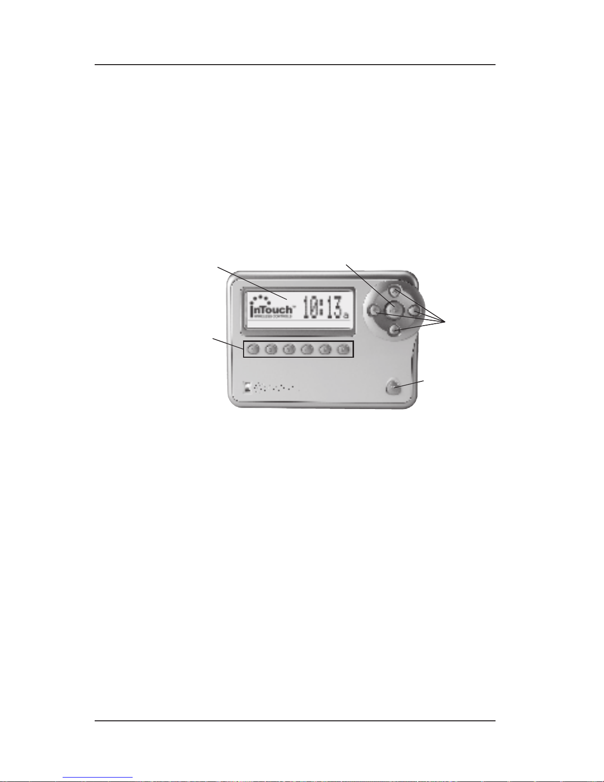
The In-Wall Master Controller provides system control
as well as programming capability.
Display Screen — displays the correct time of day,
automatically adjusted for daylight savings time if you
prefer, and also displays programming menus as you
rene and customize your system.
<ARROW> buttons — used to navigate the programming
menus.
<ENTER> button — makes selections and saves your work
during programming sessions, also toggles scene states
between ON and OFF.
<HOME> button — “steps back” one screen during
programming sessions, also deselects multiple scene
buttons when they are highlighted.
<SCENE SELECTION> buttons — used to activate scenes
that are assigned to the button.
<SCENE SELECTION>
buttons
<ENTER>
button
<ARROW>
buttons
<HOME>
button
Display Screen
<SCENE SELECTION>
buttons
<ENTER>
button
<ARROW>
buttons
<HOME>
button
Display Screen
Page 38

38 InTouch™ User Guide
Copyright © 2006 Intermatic, Inc.
Minimum Recommended Set Up
This is the short list of the main functions you’ll want the
In-Wall Master Controller to be doing.
It’s clear that you’ll need to set the correct time and
date. That’s rst. See page 41.
Next, it is extremely helpful to organize all the devices
throughout the house into rooms. Otherwise, each time
you’re setting up a scene, you’ll have to scroll through
the entire list of devices and try to remember which are
which. See page 44.
Then, if you haven’t already set up scenes, it may be
easier to set them up or create them from the In-Wall
Master Controller because you won’t have to walk all
through the house with the Hand-Held. For instructions
on Working with Scenes, see page 55.
NOTE: If you have already created scenes using the
Hand-Held and Base, you will see them listed on the
In-Wall Master Controller’s display shown according
to the ID number of the device and the last number
indicating the button assigned to activate them. For
example:
Remote C001B001 = Activated by Remote 1, Button 1
Remote C001B002 = Activated by Remote 1, Button 2
Remote C002B001 = Activated by Remote 2, Button 1
Remote C002B002 = Activated by Remote 2, Button 2
etc.
Note that the rst characters describe the device.
You’ll want to note this information when you are
creating events with the In-Wall Master Controller to
activate these scenes. See page 58 to rename these
scenes to something more user friendly, like “Kids’
Room” or “Watching Movies.”
After creating scenes with the In-Wall Master Controller,
you’ll want to assign scenes to the six buttons on the
device. See page 56.
You’ll also need to know how to manually turn scenes
on and off using the In-Wall Master Controller. See page
55 and 58.
Page 39

An Introduction to the In-Wall Master Controller 39
Providing a brighter solution.™
Once you have created scenes, you’ll want to set some
of them to turn on and off when you want. We have
provided detailed, step-by-step instructions for the most
common or popular kinds of events:
An ON/OFF Recurring Event, like turning the
outside lights on at dusk and off at dawn. See
page 62.
A Recurring Event of Specic Duration, like
turning the outside lights on and having them stay
on for 2 hours. See page 67.
An Action Event, where pressing a button or
triggering a motion sensor makes a different thing
happen, depending on the time of day. See
page 71.
For security purposes, you can have these events
occur at random times within a 30-minute
window, giving your house a “lived-in look.” See
pages 66 and 71.
For many owners, these functions alone will justify
the addition of the In-Wall Master Controller to their
InTouch network. Other owners will want to go deeper.
Optional Programming
For owners who want to learn more about what the
In-Wall Master Controller can do — who want to
make their InTouch lifestyle a little more pleasant
and convenient — additional renements can be
programmed. Optional programming can be done with:
Scenes — those groups of devices that have been set to
operate together the way you want:
Conguring a scene (for example, adjusting the list
of devices included in an existing scene). See page
54.
Renaming a scene. This is helpful when viewing
scenes on the In-Wall Master Controller’s display,
since the system gives scenes generic names like
“Scene 1” and “Scene 2.” You can give them more
user-friendly names like “Kids’ Room” or “Watching
Movies.” See page 58.
•
•
•
•
•
•
Page 40

40 InTouch™ User Guide
Copyright © 2006 Intermatic, Inc.
Deleting a scene. See page 60. Remember, it’s
always a good idea to remove unused events,
scenes, and devices to maximize the system’s
responsiveness.
Events — which trigger scenes can also be ne-tuned
in many ways. We have already covered Timer Events.
Here you’ll nd step-by-step instructions for:
Changing the duration — the length of time an event
lasts. See page 76.
Renaming an event, helpful when viewing events
on the In-Wall Master Controller’s display, where
you might want to change the name of an event to
something more specic, like “Outside On.” See
page 77.
Deleting an event from the system when you no
longer need it. It’s always a good idea to remove
unused events, scenes, and devices to maximize the
system’s responsiveness. See page 79.
What To Do First
Make a list of the basic and advanced functions you
want to accomplish. Go after the basics rst, then tackle
the more advanced optional programming. The page
numbers on the preceding pages will guide you to the
step-by-step instructions that will help you get the job
done with minimal difculty.
•
•
•
•
Page 41

Step-by-Step with the In-Wall Master Controller 41
Providing a brighter solution.™
Section 5:
Step-by-Step with the In-Wall
Master Controller
Introduction
This section provides step-by-step instructions for
working with the menus of the In-Wall Master
Controller. Before you use this section, we recommend
that you read Section 4 and make a list of the
programming you want to accomplish — along with
page numbers for nding the appropriate information
— and then use this section as a reference guide.
Setting System Time
Overview
The In-Wall Master Controller lets you set up scenes that
are activated by a timer. Before you can create a timercontrolled scene, you must set the controller’s time.
Things You Should Know about Time
The In-Wall Master Controller is a more sophisticated
timekeeper than a simple clock. Since it keeps track of
the date as well as the time, you have the option to:
Automatically adjust for daylight savings time.
Automatically adjust to changes in sunrise and
sunset — useful if you want to turn lights on and off
at dawn and dusk, which change between summer
and winter. The system can calculate the seasonal
change.
Accommodate how far north or south you live,
automatically adjusting for differences in sunrise and
sunset.
With the In-Wall Master Controller programmed
correctly, you never have to make manual adjustments.
•
•
•
Page 42
42 InTouch™ User Guide
Copyright © 2006 Intermatic, Inc.
Procedure
During programming, use the <ARROW> buttons to
navigate to your selections on the screen. Use the
<RIGHT> arrow to advance to the next item.
NOTE: If you pause for more than 30 seconds during
the programming procedure, the In-Wall Master
Controller will time out and
exit programming mode.
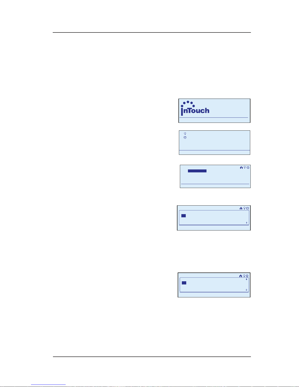
Begin at the InTouch Home
Screen as shown.
Press <ENTER>. The screen
displays the Main Menu.
Scroll with the <UP/DOWN>
arrows to select Setup,
then press <ENTER>. The
screen displays system
setup options.
Select Set Time, then
press <ENTER>. The screen
displays elds for setting
Date, as shown.
Scroll with the <UP/DOWN> arrows to set the correct
Month.
Press the <RIGHT> arrow to select the Day eld, then
<UP/DOWN> to set the correct Day.
Repeat this procedure to
set the correct Year, then
press the <RIGHT> arrow
or <ENTER>. The screen
computes the day of the week and advances to Set
Time.
Scroll with the <UP/DOWN> arrows to set the correct
Hour.
1.
2.
3.
4.
5.
6.
7.
a
WIRELESS CONTROLS
TM
11:25
a
WIRELESS CONTROLS
TM
11:25
My Scenes
My Events
Setup
11:25a
My Scenes
My Events
Setup
11:25a
Setup Home
Set Time
Setup
11:25a
Setup Network
Setup Home
Set Time
Setup
11:25a
Setup Network
11:25a
Set Date:
01-01-06 Thursday
Set Time:
Setup>Setup Home
11:25a
Set Date:
01-01-06 Thursday
Set Time:
Setup>Setup Home
11:25a
Set Time:
1:45p
Daylight Savings:
Setup>Setup Home
11:25a
Set Time:
1:45p
Daylight Savings:
Setup>Setup Home
Page 43
Step-by-Step with the In-Wall Master Controller 43
Providing a brighter solution.™
Press the <RIGHT> arrow to select the Minutes eld,
then scroll <UP/DOWN> to set the correct Minutes.
Repeat this procedure
to set whether the time
is AM or PM, then
press the <RIGHT> arrow
or <ENTER>. The screen displays elds for selecting
whether you want the system to Automatically adjust
for Daylight Savings Time. (Choose Off if you live
in a part of the country that does not use daylight
savings time.)
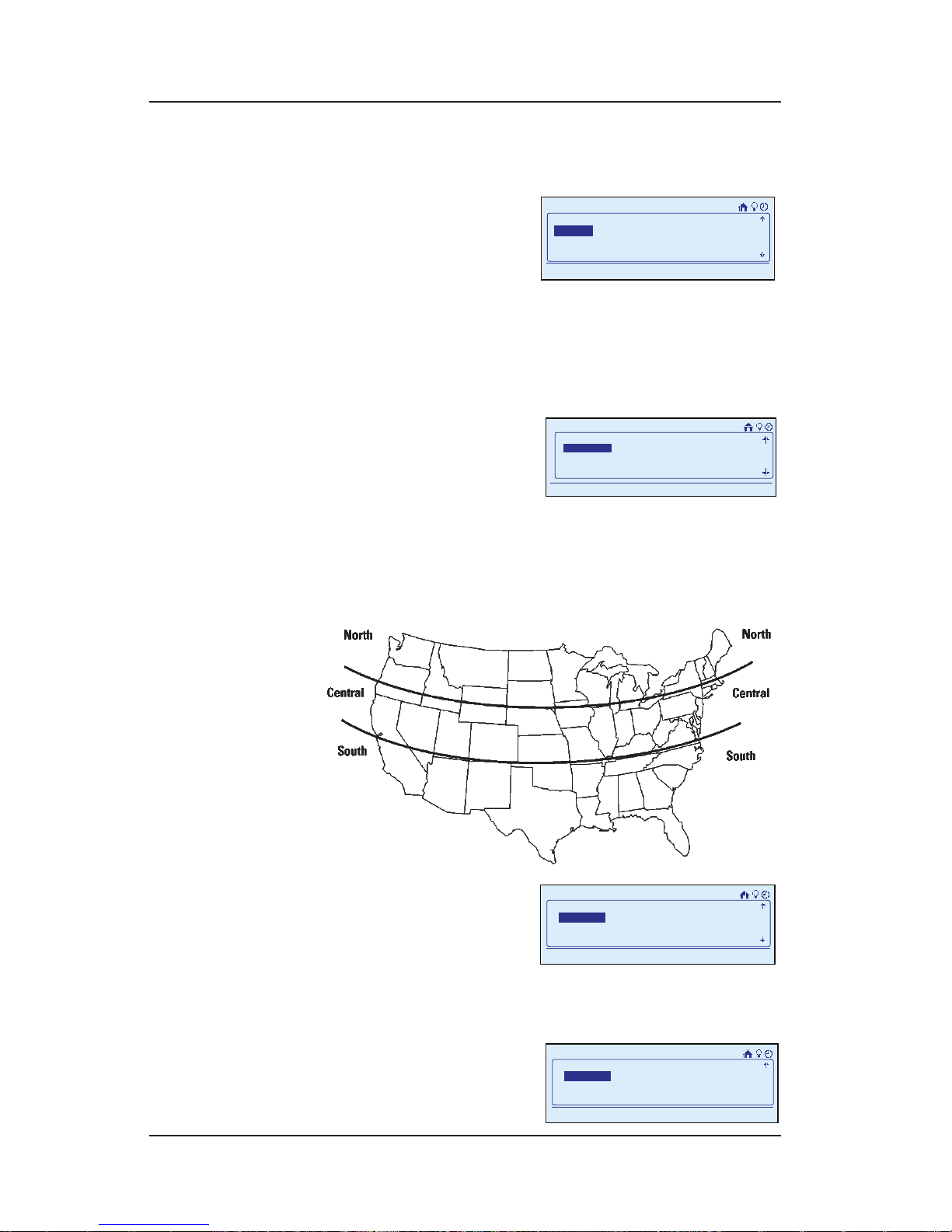
Scroll with the <UP/
DOWN> arrows to make
your selection, then press
the <RIGHT> arrow or
<ENTER>. The screen displays elds for setting System
Latitude, as shown.
Using the map shown below, locate the part of the
country (North, Central, or South) where you live.
Scroll with the <UP/
DOWN> arrows to select
the section of the
country where you live,
then press the <RIGHT> arrow or <ENTER>. The screen
displays the computed time for sunrise, as shown.
Recommended: You can
enter the exact time for
sunrise as provided in
your daily newspaper.
8.
9.
10.
11.
12.
13.
11:25a
Daylight Savings:
Auto
System Latitude:
Setup>Setup Home
11:25a
Daylight Savings:
Auto
System Latitude:
Setup>Setup Home
11:25a
System Latitude:
Central
Sunrise [Computed 5:49a]:
Setup>Setup Home
11:25a
System Latitude:
Central
Sunrise [Computed 5:49a]:
Setup>Setup Home
11:25a
Setup>Setup Home
Sunrise [ Computed 6:23a ]:
6:25a
Sunset [ Computed 6:20p ]:
11:25a
Setup>Setup Home
Sunrise [ Computed 6:23a ]:
6:25a
Sunset [ Computed 6:20p ]:
11:25a
Setup>Setup Home
Sunset [ Computed 6:20p ]:
6:20p
Save & Close
11:25a
Setup>Setup Home
Sunset [ Computed 6:20p ]:
6:20p
Save & Close
Page 44

44 InTouch™ User Guide
Copyright © 2006 Intermatic, Inc.
To set exact time, scroll with the <UP/DOWN>
arrows to set today’s sunrise time, then press the
<RIGHT> arrow.
To skip setting exact time, press the <RIGHT> arrow
to bypass the step.
In either case, the screen displays a computed time
for sunset, as shown.
Recommended: As with sunrise, you can enter the
exact time for sunset. Scroll with the <UP/DOWN>
arrows to set the exact sunset time, then press the
<RIGHT> arrow, or press the <RIGHT> arrow to bypass
the step. In either case, the cursor highlights Save &
Close.
Press <ENTER>. Your settings are saved and the Main
Menu screen reappears. After a few seconds, the
Home Screen reappears, displaying the correct time.
Grouping Devices into Rooms
Overview
A room is a group of devices that:
Have been installed inside a room of the house, or
Will be controlled by scenes programmed for a room
of the house, both inside and outside the room.
In this case, for example, you might also include
a hallway light located outside the room along
with the devices inside the room since you plan to
program scenes that will control the hallway light as
well.
To group devices into rooms, you must rst add devices
to the network (see page 14), create the rooms, and
then add the appropriate devices to the rooms you have
created.
•
•
14.
15.
•
•
Page 45
Step-by-Step with the In-Wall Master Controller 45
Providing a brighter solution.™
Creating Rooms
Creating rooms means to establish the rooms or
groupings within the house for the devices the InTouch
system will be controlling.
During programming, use the <ARROW> buttons to
navigate to your selections on the screen. Use the
<RIGHT> arrow to advance to the next item.
NOTE: If you pause for more than 30 seconds during
the programming procedure, the In-Wall Master
Controller will time out and
exit programming mode.
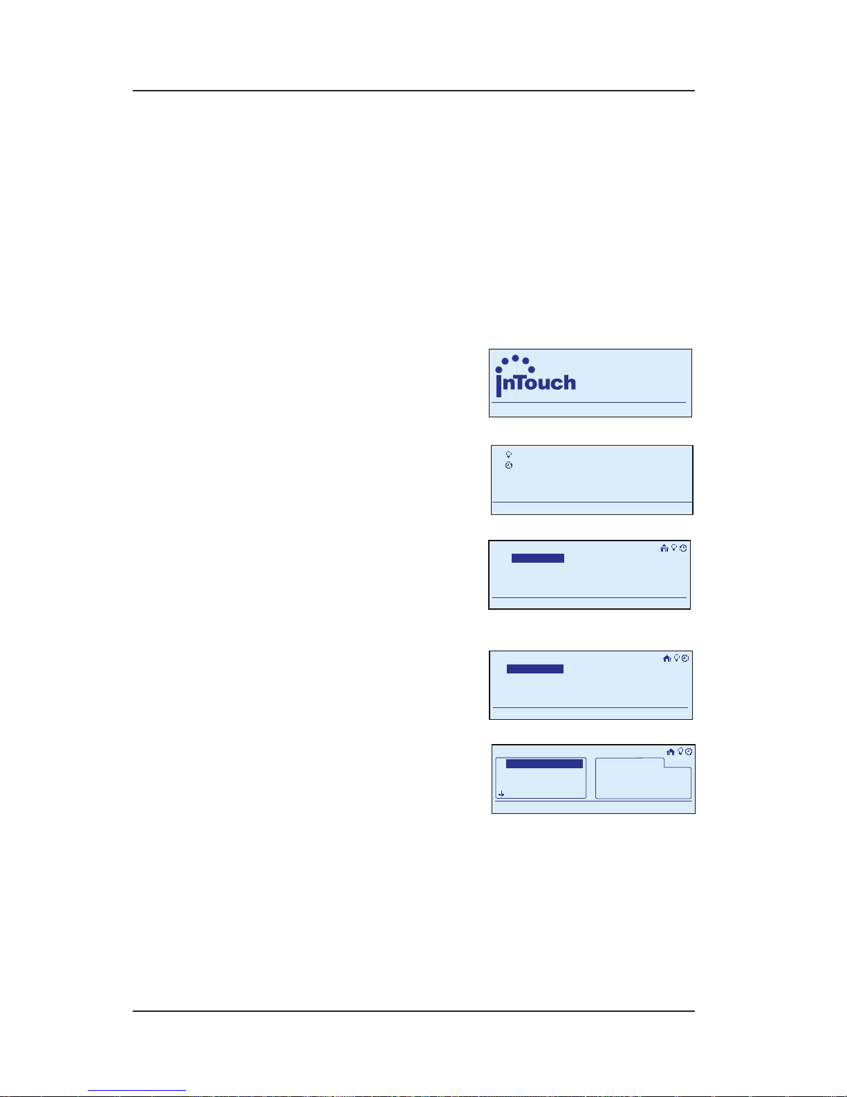
Begin at the InTouch Home
Screen as shown.
Press <ENTER>. The screen
displays the Main Menu.
Scroll with the <UP/DOWN>
arrows to select Setup,
then press <ENTER>. The
screen displays system
setup options.
Select Setup Home, then
press <ENTER>. The screen
displays options for
setting up the home.
Select Add Rooms, then
press <ENTER>. The screen
displays a list of room
names in the box on the
left.
NOTE: If the room name you want to use is not
displayed, choose an existing room name and
rename it later. See instructions for renaming rooms
on page 48.
1.
2.
3.
4.
a
WIRELESS CONTROLS
TM
11:25
a
WIRELESS CONTROLS
TM
11:25
My Scenes
My Events
Setup
11:25a
My Scenes
My Events
Setup
11:25a
Setup Home
Set Time
Setup
11:25a
Setup Network
Setup Home
Set Time
Setup
11:25a
Setup Network
Add Rooms
Edit Rooms
11:25a
Setup>Setup Home
Add Rooms
Edit Rooms
11:25a
Setup>Setup Home
>
Bedroom
Den
Garage
Bathroom
11:25a
Setup>Setup Home>Add Rooms
>
Bedroom
Den
Garage
Bathroom
11:25a
Setup>Setup Home>Add Rooms
Page 46
46 InTouch™ User Guide
Copyright © 2006 Intermatic, Inc.
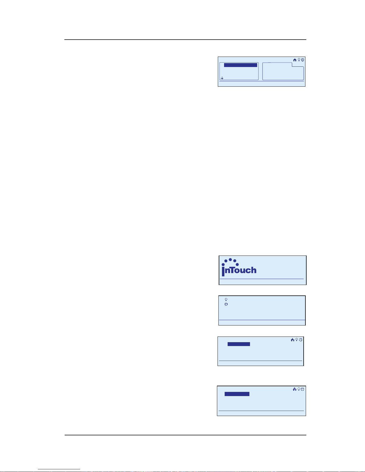
Highlight a room on the
left and press <ENTER>.
Note that the room name
copies to the box on the
right. Repeat this procedure until you have created
the rooms you will need for programming the house.
Press the <HOME> button when you are nished. The
screen returns to the Main Menu. Having created the
rooms, you must now add the appropriate devices to
the rooms you have created.
Adding Devices to Rooms
Once you have created the rooms, use the editing
function to add the appropriate devices to the rooms
you have created.
During programming, use the <ARROW> buttons to
navigate to your selections on the screen. Use the
<RIGHT> arrow to advance to the next item.
NOTE: If you pause for more than 30 seconds during
the programming procedure, the In-Wall Master
Controller will time out and
exit programming mode.
Begin at the InTouch Home
Screen as shown.
Press <ENTER>. The screen
displays the Main Menu.
Scroll with the <UP/DOWN>
arrows to select Setup,
then press <ENTER>. The
screen displays system
setup options.
Select Setup Home, then
press <ENTER>. The screen
displays options for
setting up the home.
5.
6.
1.
2.
3.
>
Bedroom
Den
Garage
Bathroom
11:25a
Setup>Setup Home>Add Rooms
Bathroom 1
Bedroom 1
Bedroom 2
>
Bedroom
Den
Garage
Bathroom
11:25a
Setup>Setup Home>Add Rooms
Bathroom 1
Bedroom 1
Bedroom 2
a
WIRELESS CONTROLS
TM
11:25
a
WIRELESS CONTROLS
TM
11:25
My Scenes
My Events
Setup
11:25a
My Scenes
My Events
Setup
11:25a
Setup Home
Set Time
Setup
11:25a
Setup Network
Setup Home
Set Time
Setup
11:25a
Setup Network
Add Rooms
Edit Rooms
11:25a
Setup>Setup Home
Add Rooms
Edit Rooms
11:25a
Setup>Setup Home
Page 47
Step-by-Step with the In-Wall Master Controller 47
Providing a brighter solution.™
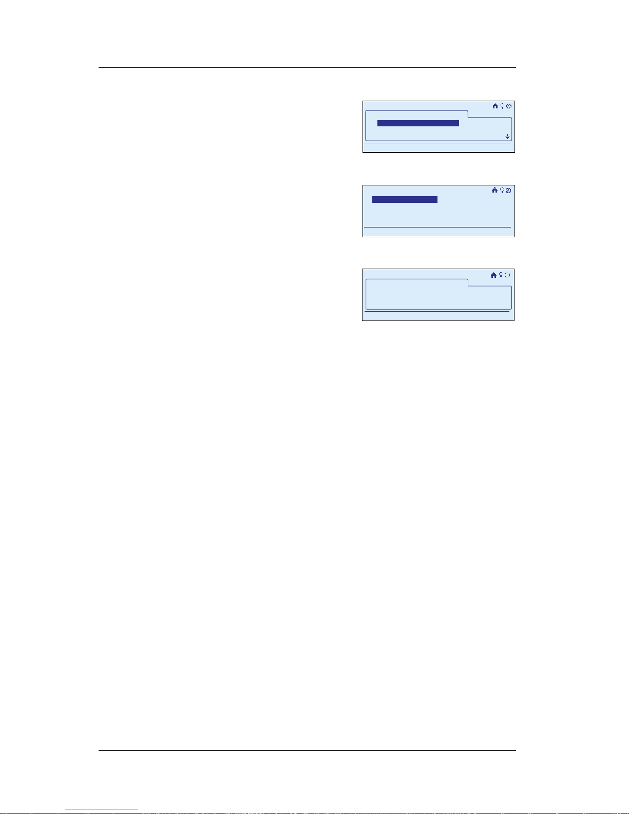
Select Edit Rooms, then
press <ENTER>. The screen
displays the list of the
rooms you have created
for the house.
Select the rst room you
want to edit and press
<ENTER>. The screen
displays the options for
editing the room.
Select Add Device, then
press <ENTER>. The screen
displays the room name
by itself.
Press <ENTER> to begin adding devices to the selected
room.
Now go around the room and change the state of
each device you want to include in the room: turn
it ON, turn it OFF, etc. If any controllers are to be
included in the room, press any <SCENE SELECTION>
button.
When you are nished, press <ENTER> to complete
the procedure. The display returns to the Main Menu,
and automatically exits programming mode in about
30 seconds if there’s no activity.
Repeat this procedure for the other rooms in the house.
Removing a Device from a Room
If you want to reclassify a device from one room to
another:
Use the following procedure to “remove” the device
from one room.
Use the procedure on page 46 to “add” the device to
a new room.
During programming, use the <ARROW> buttons to
navigate to your selections on the screen. Use the
<RIGHT> arrow to advance to the next item.
4.
5.
6.
7.
7.
8.
9.
•
•
My Rooms
Bathroom 1
11:25a
Setup>Setup Home>Edit Rooms
Bedroom 1
Bedroom 2
My Rooms
Bathroom 1
11:25a
Setup>Setup Home>Edit Rooms
Bedroom 1
Bedroom 2
Remove Device
Rename Room
Delete Room
Add Device
11:25a
Setup>Setup Home>Edit Rooms
Remove Device
Rename Room
Delete Room
Add Device
11:25a
Setup>Setup Home>Edit Rooms
Bathroom 1
11:25a
Setup>Setup Home>Edit Rooms
Bathroom 1
11:25a
Setup>Setup Home>Edit Rooms
Page 48
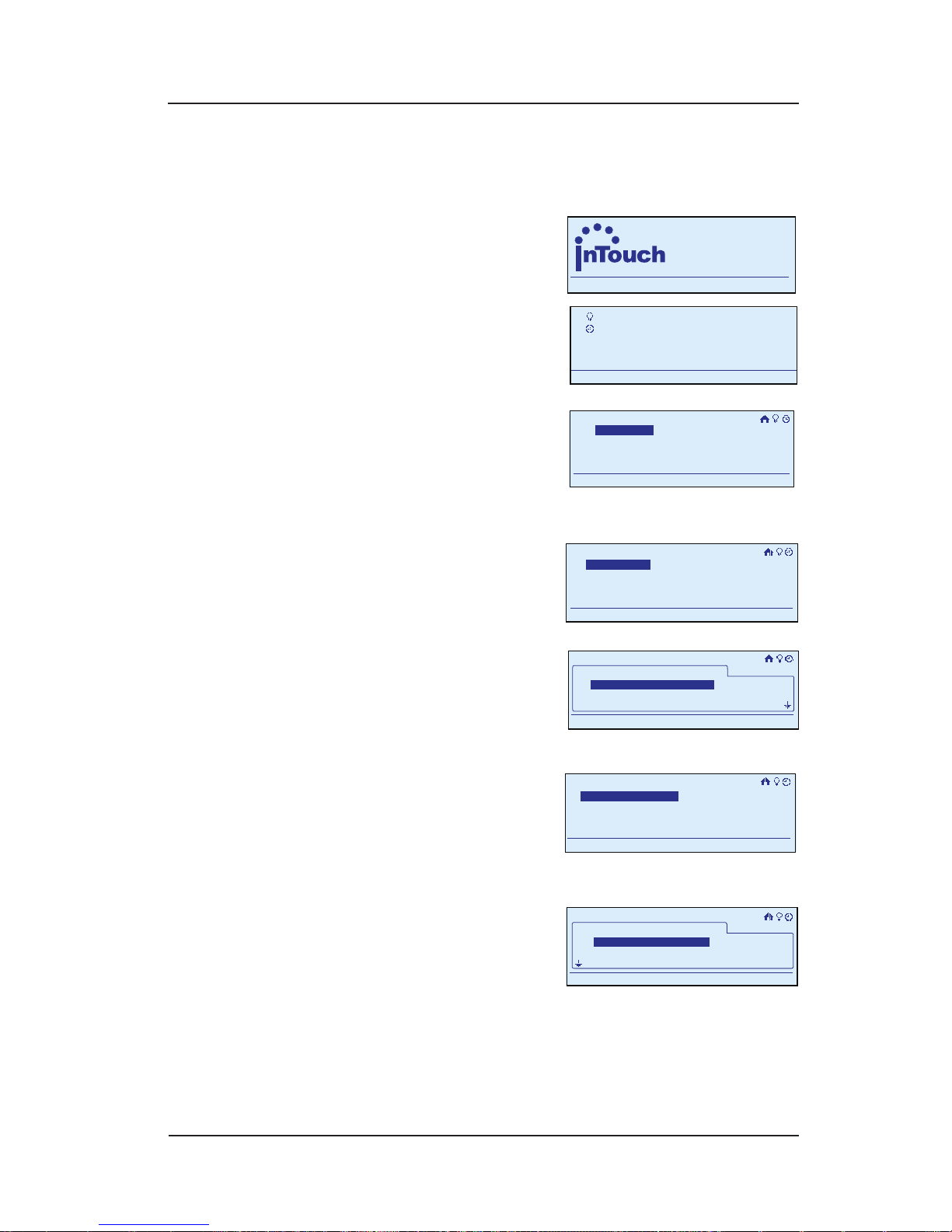
48 InTouch™ User Guide
Copyright © 2006 Intermatic, Inc.
NOTE: If you pause for more than 30 seconds during
the programming procedure, the In-Wall Master
Controller will time out and exit programming mode.
Begin at the InTouch Home
Screen as shown.
Press <ENTER>. The screen
displays the Main Menu.
Scroll with the <UP/DOWN>
arrows to select Setup,
then press <ENTER>. The
screen displays system
setup options.
Select Setup Home, then
press <ENTER>. The screen
displays options for
setting up the home.
Select Edit Rooms, then
press <ENTER>. The screen
displays the list of the
rooms you have created
for the house.
Select the room from
which you want to
remove a device and
press <ENTER>. The screen
displays the options for editing the room.
Select Remove Device
and press <ENTER>. The
screen displays the room’s
devices.
Select the device you want to remove as shown and
press <ENTER>. Conrm that you want to remove the
device. The device is returned to the “Unassigned”
room, ready for assignment to another room.
1.
2.
3.
4.
5.
6.
7.
a
WIRELESS CONTROLS
TM
11:25
a
WIRELESS CONTROLS
TM
11:25
My Scenes
My Events
Setup
11:25a
My Scenes
My Events
Setup
11:25a
Setup Home
Set Time
Setup
11:25a
Setup Network
Setup Home
Set Time
Setup
11:25a
Setup Network
Add Rooms
Edit Rooms
11:25a
Setup>Setup Home
Add Rooms
Edit Rooms
11:25a
Setup>Setup Home
My Rooms
Bathroom 1
11:25a
Setup>Setup Home>Edit Rooms
Bedroom 1
Bedroom 2
My Rooms
Bathroom 1
11:25a
Setup>Setup Home>Edit Rooms
Bedroom 1
Bedroom 2
Remove Device
Rename Room
Delete Room
Add Device
11:25a
Setup>Setup Home>Edit Rooms
Remove Device
Rename Room
Delete Room
Add Device
11:25a
Setup>Setup Home>Edit Rooms
Bathroom 1
11:25a
Setup>Setup Home>Edit Rooms
Done>
Binary Switch 3
Binary Switch 2
Binary Switch 1
Bathroom 1
11:25a
Setup>Setup Home>Edit Rooms
Done>
Binary Switch 3
Binary Switch 2
Binary Switch 1
Page 49
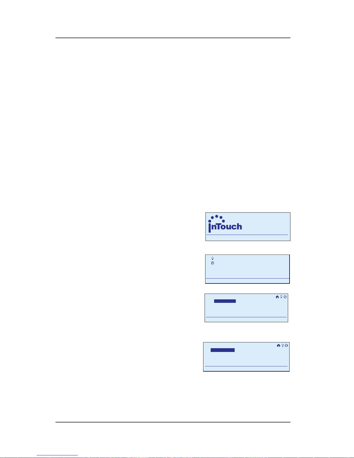
Step-by-Step with the In-Wall Master Controller 49
Providing a brighter solution.™
When you are nished, scroll with the <DOWN>
arrow to highlight Done, then press <ENTER> to nish
the procedure. The display returns to the Main Menu
screen, and automatically exits programming mode
in about 30 seconds if there’s no activity.
Renaming a Room
Renaming a room makes the In-Wall Master Controller
more user-friendly in everyday use. Giving a child’s
bedroom the child’s name, for example, means there
will be no question about whether Otto’s bedroom is
“Bedroom 1” or “Bedroom 2.”
During programming, use the <ARROW> buttons to
navigate to your selections on the screen. Use the
<RIGHT> arrow to advance to the next item.
NOTE: If you pause for more than 30 seconds during
the programming procedure, the In-Wall Master
Controller will time out and
exit programming mode.
Begin at the InTouch Home
Screen as shown.
Press <ENTER>. The screen
displays the Main Menu.
Scroll with the <UP/DOWN>
arrows to select Setup,
then press <ENTER>. The
screen displays system
setup options.
Select Setup Home, then
press <ENTER>. The screen
displays options for
setting up the home.
8.
1.
2.
3.
a
WIRELESS CONTROLS
TM
11:25
a
WIRELESS CONTROLS
TM
11:25
My Scenes
My Events
Setup
11:25a
My Scenes
My Events
Setup
11:25a
Setup Home
Set Time
Setup
11:25a
Setup Network
Setup Home
Set Time
Setup
11:25a
Setup Network
Add Rooms
Edit Rooms
11:25a
Setup>Setup Home
Add Rooms
Edit Rooms
11:25a
Setup>Setup Home
Page 50
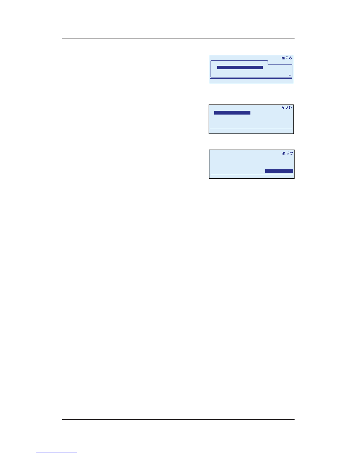
50 InTouch™ User Guide
Copyright © 2006 Intermatic, Inc.
Select Edit Rooms, then
press <ENTER>. The screen
displays the list of the
rooms you have created
for the house.
Select the room you
want to rename and
press <ENTER>. The screen
displays the options for
editing the room.
Select Rename Room and
press <ENTER>. The screen
displays the old name
and prompts you to enter
the new name.
Scroll with the <UP/DOWN> arrows to change the rst
character of the new name, then press the <RIGHT>
arrow to select the second character, and continue
creating the new name.
The characters repeat in a loop in the order shown
below, starting from wherever you are at the time.
There is a “blank space” symbol between the “~”
symbol and the “!” symbol, as shown below.
ABCDEFGHIJKLMNOPQRSTUVWXYZ[\]^_`
abcdefghijklmnopqrstuvwxyz{|}~ !
”#$%&’()*+,-./0123456789:;<=>?@
NOTE: To shorten a name or “erase” unwanted
characters, override them with a “blank space”
character.
When you are satised with the new name of the
room, press the <ENTER> button to highlight Save
& Close, then press <ENTER> again to nish the
renaming procedure. The display returns to the Main
Menu screen, and automatically exits programming
mode in about 30 seconds if there’s no activity.
4.
5.
6.
7.
8.
My Rooms
Bathroom 1
11:25a
Setup>Setup Home>Edit Rooms
Bedroom 1
Bedroom 2
My Rooms
Bathroom 1
11:25a
Setup>Setup Home>Edit Rooms
Bedroom 1
Bedroom 2
Remove Device
Rename Room
Delete Room
Add Device
11:25a
Setup>Setup Home>Edit Rooms
Remove Device
Rename Room
Delete Room
Add Device
11:25a
Setup>Setup Home>Edit Rooms
11:25a
Enter room name
Otto's Bedroom
Save & Close
Setup>Setup Home>Edit Rooms
11:25a
Enter room name
Otto's Bedroom
Save & Close
Setup>Setup Home>Edit Rooms
Page 51
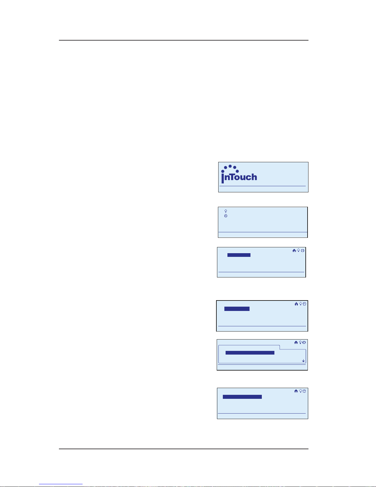
Step-by-Step with the In-Wall Master Controller 51
Providing a brighter solution.™
Deleting a Room
Deleting a room lets you correct your original
conguration. When you delete a room, any devices
assigned to the room are returned to the “Unassigned”
room.
During programming, use the <ARROW> buttons to
navigate to your selections on the screen. Use the
<RIGHT> arrow to advance to the next item.
NOTE: If you pause for more than 30 seconds during
the programming procedure, the In-Wall Master
Controller will time out and
exit programming mode.
Begin at the InTouch Home
Screen as shown.
Press <ENTER>. The screen
displays the Main Menu.
Scroll with the <UP/DOWN>
arrows to select Setup,
then press <ENTER>. The
screen displays system
setup options.
Select Setup Home, then
press <ENTER>. The screen
displays options for
setting up the home.
Select Edit Rooms, then
press <ENTER>. The screen
displays the list of the
rooms you have created
for the house.
Select the room you
want to delete and press
<ENTER>. The screen
displays the options for
editing the room.
1.
2.
3.
4.
5.
a
WIRELESS CONTROLS
TM
11:25
a
WIRELESS CONTROLS
TM
11:25
My Scenes
My Events
Setup
11:25a
My Scenes
My Events
Setup
11:25a
Setup Home
Set Time
Setup
11:25a
Setup Network
Setup Home
Set Time
Setup
11:25a
Setup Network
Add Rooms
Edit Rooms
11:25a
Setup>Setup Home
Add Rooms
Edit Rooms
11:25a
Setup>Setup Home
My Rooms
Bathroom 1
11:25a
Setup>Setup Home>Edit Rooms
Bedroom 1
Bedroom 2
My Rooms
Bathroom 1
11:25a
Setup>Setup Home>Edit Rooms
Bedroom 1
Bedroom 2
Remove Device
Rename Room
Delete Room
Add Device
11:25a
Setup>Setup Home>Edit Rooms
Remove Device
Rename Room
Delete Room
Add Device
11:25a
Setup>Setup Home>Edit Rooms
Page 52

52 InTouch™ User Guide
Copyright © 2006 Intermatic, Inc.
Select Delete Room and
press <ENTER>. The screen
displays the room and
asks if you want to Save
& Close.
Select Yes with the <RIGHT/LEFT> arrows, then press
<ENTER>. The room is deleted and the display returns
to the Main Menu screen, and automatically exits
programming mode in about 30 seconds if there’s no
activity.
NOTE: Any devices that were assigned to the room
being deleted will show up in the “Unassigned”
folder.
Working with Scenes
Overview
A scene is a group of devices that have been set to
respond the way you want. For example, if you set
up the lighting in your living room a certain way for
watching a movie on your big screen TV, you’ve created
a scene. Another scene might be to turn on all the lights
on your stairway and upstairs hallway. Or your porch
light, the lights in your yard, and the light at the end of
your driveway.
Adding a Scene
Adding a scene means to create a new scene by
grouping devices you want to control. This is the timesaving way of creating scenes where you can work
from the In-Wall Master Controller instead of walking
throughout the house.
During programming, use the <ARROW> buttons to
navigate to your selections on the screen. Use the
<RIGHT> arrow to advance to the next item.
NOTE: If you pause for more than 30 seconds during
the programming procedure, the In-Wall Master
Controller will time out and exit programming mode.
6.
7.
Remove Bathroom 1
Save & Close
No
11:25a
Setup>Setup Home>Edit Rooms
Yes
Remove Bathroom 1
Save & Close
No
11:25a
Setup>Setup Home>Edit Rooms
Yes
Page 53
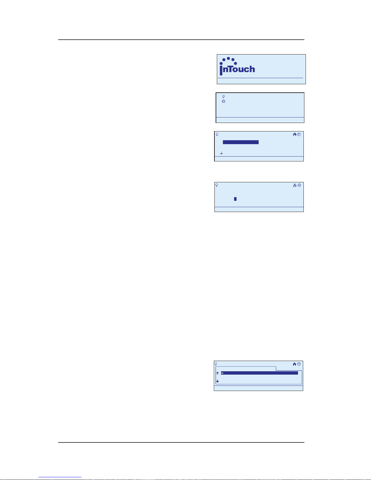
Step-by-Step with the In-Wall Master Controller 53
Providing a brighter solution.™
Begin at the InTouch Home
Screen as shown.
Press <ENTER>. The screen
displays the Main Menu.
Scroll with the <UP/
DOWN> arrows to select
My Scenes, then press
<ENTER>. The screen
displays options for working with scenes.
Select Add Scene, then
press <ENTER>. The screen
displays the new scene,
giving it a generic name
like “Scene 1” and highlighting the rst letter in the
scene name (“S” in “Scene 1”).
OPTION: You can rename the scene at this time
to something that’s more descriptive, like “Kids’
Bedroom” or “Back Yard.”
To rename the scene at this time, follow
instructions on page 57.
To skip renaming at this time, press <ENTER>. The
screen highlights Congure.
Press <ENTER> to begin the procedure of conguring
the details of the scene. The screen displays a list of
rooms.
Scroll to select a room and press <ENTER>.
Scroll to select a device
you want to adjust.
Press the <RIGHT/LEFT>
arrows to adjust the value
you want. You will have one of three possibilities:
For a switch—ON and OFF.
1.
2.
3.
4.
•
•
5.
6.
7.
8.
•
a
WIRELESS CONTROLS
TM
11:25
a
WIRELESS CONTROLS
TM
11:25
My Scenes
My Events
Setup
11:25a
My Scenes
My Events
Setup
11:25a
My Scenes
Turn on Scene
Configure Scene
Add Scene
Rename Scene
11:25a
My Scenes
Turn on Scene
Configure Scene
Add Scene
Rename Scene
11:25a
>Add Scene
Enter Scene name
Scene 1
11:25a
S
Configure>
>Add Scene
Enter Scene name
Scene 1
11:25a
S
Configure>
>Configure Scene
11:25a
Scene 1
Binary Switch 5
Multi Level Switch 3
OFF
75%
Bathroom1
Bathroom 1
>Configure Scene
11:25a
Scene 1
Binary Switch 5
Multi Level Switch 3
OFF
75%
Bathroom1
Bathroom 1
Page 54
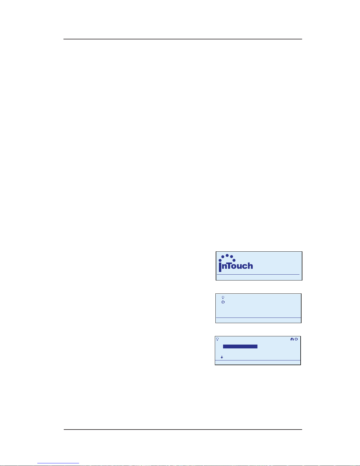
54 InTouch™ User Guide
Copyright © 2006 Intermatic, Inc.
For a dimmer switch—OFF and a percentage of
ON.
For a switch not in the scene—three dashes (it
may be added to the scene at this point).
When you are satised, press the <DOWN> arrow to
highlight Save & Close, then press <ENTER> to nish
the procedure. The display returns to the Main Menu
screen, and automatically exits programming mode
in about 30 seconds if there’s no activity.
Configuring a Scene (Making Changes
to Scenes)
Conguring a scene means to adjust the devices that are
included in a pre-existing scene and are affected when
the scene is turned on or off.
During programming, use the <ARROW> buttons to
navigate to your selections on the screen. Use the
<RIGHT> arrow to advance to the next item.
NOTE: If you pause for more than 30 seconds during
the programming procedure, the In-Wall Master
Controller will time out and
exit programming mode.
Begin at the InTouch Home
Screen as shown.
Press <ENTER>. The screen
displays the Main Menu.
Scroll with the <UP/
DOWN> arrows to select
My Scenes, then press
<ENTER>. The screen
displays a list of options for working with scenes.
•
•
9.
1.
2.
a
WIRELESS CONTROLS
TM
11:25
a
WIRELESS CONTROLS
TM
11:25
My Scenes
My Events
Setup
11:25a
My Scenes
My Events
Setup
11:25a
My Scenes
Turn on Scene
Configure Scene
Add Scene
Rename Scene
11:25a
My Scenes
Turn on Scene
Configure Scene
Add Scene
Rename Scene
11:25a
Page 55
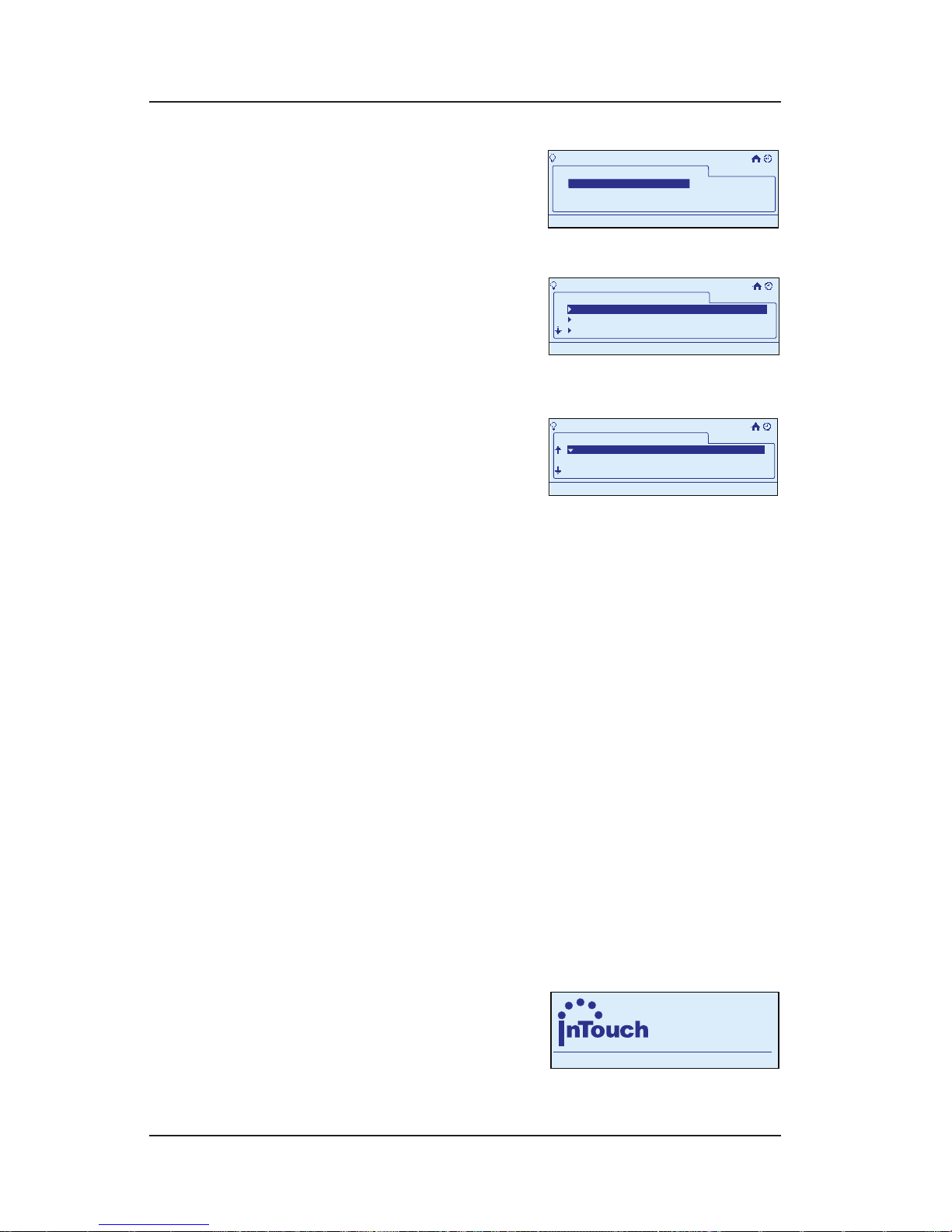
Step-by-Step with the In-Wall Master Controller 55
Providing a brighter solution.™
Select Congure Scene,
then press <ENTER>. The
screen displays a list of
the scenes programmed
in your system.
Select the scene you
want to congure and
press <ENTER>. The screen
displays the list of rooms.
Scroll to select a room and press <ENTER>.
Scroll to select a device
you want to adjust.
Press the <RIGHT/LEFT>
arrows to adjust the value
you want. You will have one of three possibilities:
For a switch—ON and OFF.
For a dimmer switch—OFF and a percentage of
ON.
For a switch not in the scene—three dashes (it
may be added to the scene at this point).
When you are satised, press the <DOWN> arrow to
highlight Save & Close, then press <ENTER> to nish
the procedure. The display returns to the Main Menu
screen, and automatically exits programming mode
in about 30 seconds if there’s no activity.
Turning a Scene ON or OFF
During programming, use the <ARROW> buttons to
navigate to your selections on the screen. Use the
<RIGHT> arrow to advance to the next item.
NOTE: If you pause for more than 30 seconds during
the programming procedure, the In-Wall Master
Controller will time out and
exit programming mode.
Begin at the InTouch Home
Screen as shown.
3.
4.
5.
6.
7.
•
•
•
8.
>Configure Scene
My Scenes
Scene1
11:25a
Scene 1
>Configure Scene
My Scenes
Scene1
11:25a
Scene 1
>Configure Scene
Scene 1
Bathroom1
Bedroom 1
Bedroom 2
11:25a
Bathroom 1
>Configure Scene
Scene 1
Bathroom1
Bedroom 1
Bedroom 2
11:25a
Bathroom 1
>Configure Scene
11:25a
Scene 1
Binary Switch 5
Multi Level Switch 3
OFF
75%
Bathroom1
Bathroom 1
>Configure Scene
11:25a
Scene 1
Binary Switch 5
Multi Level Switch 3
OFF
75%
Bathroom1
Bathroom 1
a
WIRELESS CONTROLS
TM
11:25
a
WIRELESS CONTROLS
TM
11:25
Page 56
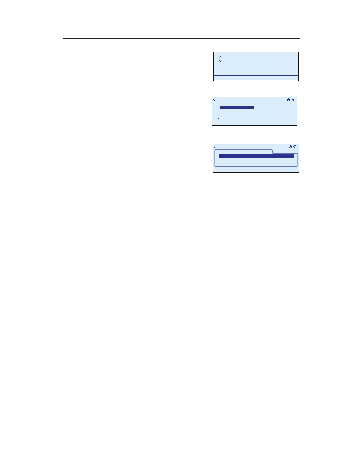
56 InTouch™ User Guide
Copyright © 2006 Intermatic, Inc.
Press <ENTER>. The screen
displays the Main Menu.
Scroll with the <UP/
DOWN> arrows to select
My Scenes, then press
<ENTER>. The screen
displays a list of options for working with scenes.
Select Turn on Scene,
then press <ENTER>. The
screen displays a list of
the scenes programmed
in your system.
Scroll with the <UP/DOWN> arrows to select the scene
you want to turn on or off. You now have three
options for adjusting the scene:
Press the <ENTER> button to turn the scene ON or
OFF.
Press and hold the <RIGHT> arrow button to raise
the level. Release the <RIGHT> arrow button when
you’re satised with the levels.
Press and hold the <LEFT> arrow button to lower
the level. Release the <LEFT> arrow button when
you’re satised with the levels.
Assigning a Scene to a Scene Selection
Button
When you assign scenes to the <SCENE SELECTION>
buttons on the In-Wall Master Controller, you can turn
them on and off by pressing the button, followed by
<ENTER> — just like on the other controllers.
During programming, use the <ARROW> buttons to
navigate to your selections on the screen. Use the
<RIGHT> arrow to advance to the next item.
1.
2.
3.
4.
•
•
•
My Scenes
My Events
Setup
11:25a
My Scenes
My Events
Setup
11:25a
My Scenes
Turn on Scene
Configure Scene
Add Scene
Rename Scene
11:25a
My Scenes
Turn on Scene
Configure Scene
Add Scene
Rename Scene
11:25a
>Turn on Scene
My Scenes
Scene1 Off
11:25a
Scene1Scene 1 OFF
>Turn on Scene
My Scenes
Scene1 Off
11:25a
Scene1Scene 1 OFF
Page 57
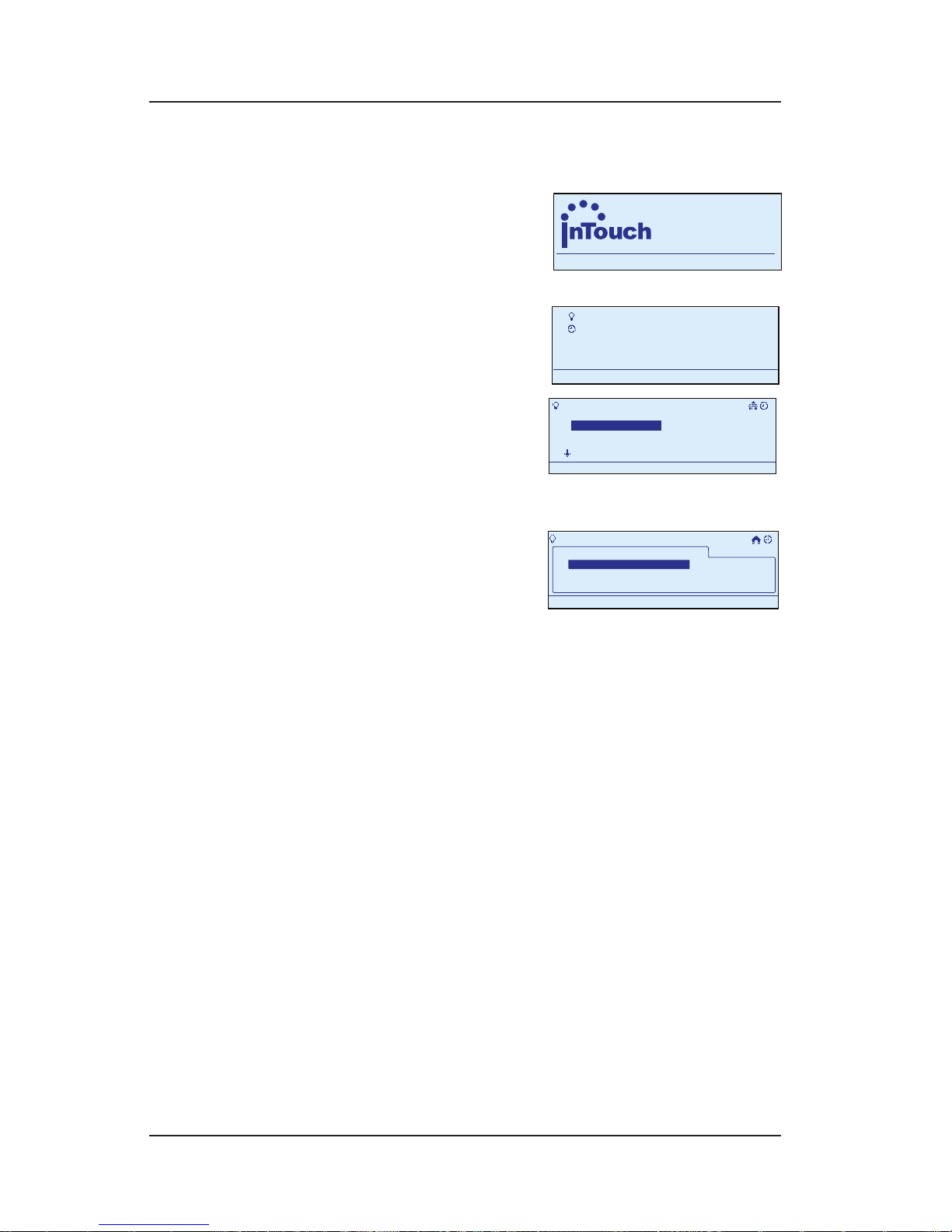
Step-by-Step with the In-Wall Master Controller 57
Providing a brighter solution.™
NOTE: If you pause for more than 30 seconds during
the programming procedure, the In-Wall Master
Controller will time out and
exit programming mode.
Begin at the InTouch Home
Screen as shown.
Press <ENTER>. The screen
displays the Main Menu.
Scroll with the <UP/
DOWN> arrows to select
My Scenes, then press
<ENTER>. The screen
displays a list of options for working with scenes.
Select Congure Scene,
then press <ENTER>. The
screen displays a list of
the scenes programmed
in your system.
Scroll with the <UP/DOWN> arrows to select the the
scene you want to control with a scene button.
Press and hold (for 4+ seconds) the <SCENE
SELECTION> button you want to control the scene.
Press the <HOME> button or wait for 30 seconds or so
for the device to exit programming mode and return
to the Home screen.
Test the programming. Press the <SCENE SELECTION>
button once to select the scene, then press the
<ENTER> button to activate the scene. Press <ENTER>
again to deactivate.
NOTE: If all of the devices in the scene are on, the
<SCENE SELECTION> button will be brightly lit.
1.
2.
3.
4.
5.
6.
7.
a
WIRELESS CONTROLS
TM
11:25
a
WIRELESS CONTROLS
TM
11:25
My Scenes
My Events
Setup
11:25a
My Scenes
My Events
Setup
11:25a
My Scenes
Turn on Scene
Configure Scene
Add Scene
Rename Scene
11:25a
My Scenes
Turn on Scene
Configure Scene
Add Scene
Rename Scene
11:25a
>Configure Scene
My Scenes
Scene1
11:25a
Scene 1
>Configure Scene
My Scenes
Scene1
11:25a
Scene 1
Page 58

58 InTouch™ User Guide
Copyright © 2006 Intermatic, Inc.
Activating a Scene with a Scene
Selection Button
After you’ve assigned scenes to scene selection buttons,
it’s easy to activate the scenes.
Press the button assigned to the scene to select it.
You now have three options for adjusting the scene:
Press the <ENTER> button to turn the scene ON or
OFF.
Press and hold the <RIGHT> arrow button to raise
the level. Release the <RIGHT> arrow button when
you’re satised with the levels.
Press and hold the <LEFT> arrow button to lower
the level. Release the <LEFT> arrow button when
you’re satised with the levels.
Press the <SCENE SELECTION> button again to deselect
it or the <HOME> button to deselect a group of scenes.
NOTE: More than one <SCENE SELECTION> button can
be pressed to adjust several scenes at the same time.
If you want to deselect all the scenes selected before
making changes, press the <HOME> button on the
controller.
Renaming a Scene
When you create a scene, the system gives it a generic
name like “Scene 1.” With this procedure, you can give
the scene a more descriptive name, like “Kids‘ Room” or
“Watching Movies.”
During programming, use the <ARROW> buttons to
navigate to your selections on the screen. Use the
<RIGHT> arrow to advance to the next item.
NOTE: If you pause for more than 30 seconds during
the programming procedure, the In-Wall Master
Controller will time out and
exit programming mode.
Begin at the InTouch Home
Screen as shown.
1.
•
•
•
2.
a
WIRELESS CONTROLS
TM
11:25
a
WIRELESS CONTROLS
TM
11:25
Page 59
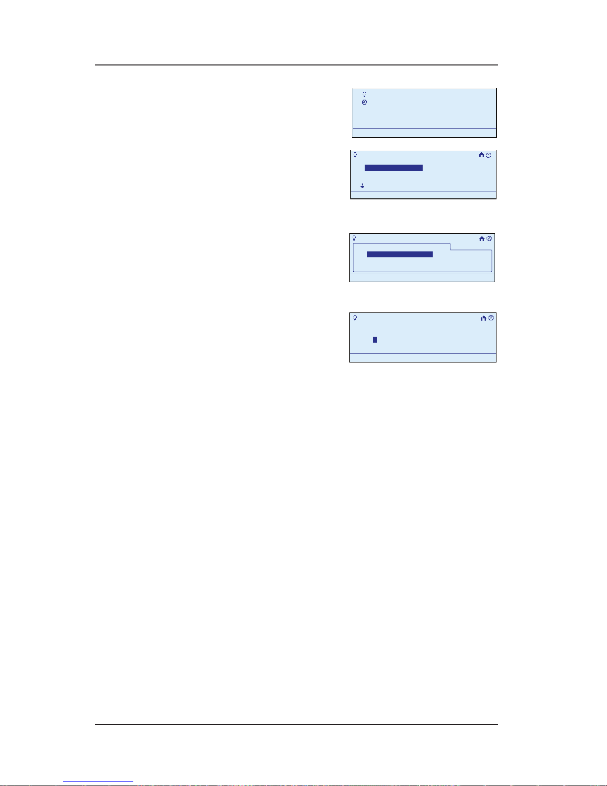
Step-by-Step with the In-Wall Master Controller 59
Providing a brighter solution.™
Press <ENTER>. The screen
displays the Main Menu.
Scroll with the <UP/DOWN>
arrows to select My
Scenes, then press
<ENTER>. The screen
displays a list of options for working with scenes.
Select Rename Scene,
then press <ENTER>. The
screen displays a list of
the scenes programmed
in your system.
Select the scene you
want to rename and press
<ENTER>. The rst letter of
the existing scene name
is highlighted.
Scroll with the <UP/DOWN> arrows to change the rst
character of the new name, then press the <RIGHT>
arrow to select the second character, and continue
creating the new name.
The characters repeat in a loop in the order shown
below, starting from wherever you are at the time.
There is a “blank space” symbol between the “~”
symbol and the “!” symbol, as shown below.
ABCDEFGHIJKLMNOPQRSTUVWXYZ[\]^_`
abcdefghijklmnopqrstuvwxyz{|}~ !
”#$%&’()*+,-./0123456789:;<=>?@
NOTE: To shorten a name or “erase” unwanted
characters, override them with a “blank space”
character.
When you are satised with the new name of the
scene, press the <ENTER> button to highlight Save
& Close, then press <ENTER> again to nish the
renaming procedure. The display returns to the Main
1.
2.
3.
4.
5.
6.
My Scenes
My Events
Setup
11:25a
My Scenes
My Events
Setup
11:25a
My Scenes
Turn on Scene
Configure Scene
Add Scene
Rename Scene
11:25a
My Scenes
Turn on Scene
Configure Scene
Add Scene
Rename Scene
11:25a
>Rename Scene
11:25a
My Scenes
Scene 1
>Rename Scene
11:25a
My Scenes
Scene 1
>Rename Scene
Enter Scene Name
Scene 10
11:25a
Save & Close
>Rename Scene
Enter Scene Name
Scene 10
11:25a
Save & Close
Page 60
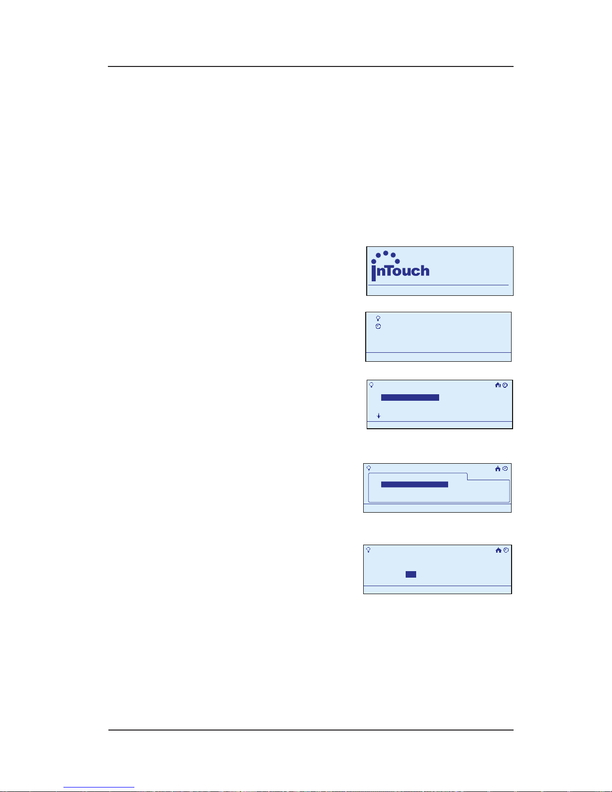
60 InTouch™ User Guide
Copyright © 2006 Intermatic, Inc.
Menu screen, and automatically exits programming
mode in about 30 seconds if there’s no activity.
Deleting a Scene
During programming, use the <ARROW> buttons to
navigate to your selections on the screen. Use the
<RIGHT> arrow to advance to the next item.
NOTE: If you pause for more than 30 seconds during
the programming procedure, the In-Wall Master
Controller will time out and
exit programming mode.
Begin at the InTouch Home
Screen as shown.
Press <ENTER>. The screen
displays the Main Menu.
Scroll with the <UP/DOWN>
arrows to select My
Scenes, then press <ENTER>.
The screen displays a list of
options for working with scenes.
Scroll down to select
Delete Scene, then press
<ENTER>. The screen
displays a list of the
scenes programmed in your system.
Select the scene you
want to delete and press
<ENTER>. The screen
requests conrmation
before it will delete the scene.
Press the <RIGHT/LEFT> arrows to select Yes, then press
<ENTER>. The system deletes the scene. The display
returns to the Main Menu screen, and automatically
exits programming mode in about 30 seconds if
there’s no activity.
1.
2.
3.
4.
5.
a
WIRELESS CONTROLS
TM
11:25
a
WIRELESS CONTROLS
TM
11:25
My Scenes
My Events
Setup
11:25a
My Scenes
My Events
Setup
11:25a
My Scenes
Turn on Scene
Configure Scene
Add Scene
Rename Scene
11:25a
My Scenes
Turn on Scene
Configure Scene
Add Scene
Rename Scene
11:25a
>Delete Scene
My Scenes
Scene 1
11:25a
>Delete Scene
My Scenes
Scene 1
11:25a
>Delete Scene
11:25a
Remove Scene1
YesNo
Save & Close
>Delete Scene
11:25a
Remove Scene1
YesNo
Save & Close
Page 61

Step-by-Step with the In-Wall Master Controller 61
Providing a brighter solution.™
Setting Up Common Events to Activate Your
Scenes
Overview
A scene is a group of devices that have been set to
respond the way you want. For example, if you set
up the lighting in your living room a certain way for
watching a movie on your big screen TV, you’ve created
a scene. Another scene might be to turn on all the lights
on your stairway and upstairs hallway. Or your porch
light, the lights in your yard, and the light at the end of
your driveway.
An event is a timer-activated scene. With the timer
functionality of the In-Wall Master Controller, you
can create events that turn scenes ON and OFF
automatically. The most common timer-event that
activates a scene is:
A Recurring Event — that regularly turns a scene ON or
OFF, either at specic times or “astronomically,” where
the ON/OFF times adjust automatically according to
sunrise and sunset (earlier sunset in winter, etc.).
This is a common safety or security setting and is a
primary reason the In-Wall Master Controller is brought
into an InTouch network. Note that the “ON” time
and the “OFF” time are individual events and must be
created separately.
Recurring events can also be created to turn a scene ON
at a specic time, on a repeating basis, and then turn
OFF after a specied duration for the event runs out.
Other events you can create include:
A One-Time Event — that turns a scene ON or OFF
one time on a specic date, whether at a specic
time or according to sunrise/sunset.
An Action Event — where the timer denes the result
of an action (e.g., a signal from a motion sensor or
the press of a button) to make the button do different
things according to what time it is. For example, a
•
•
Page 62
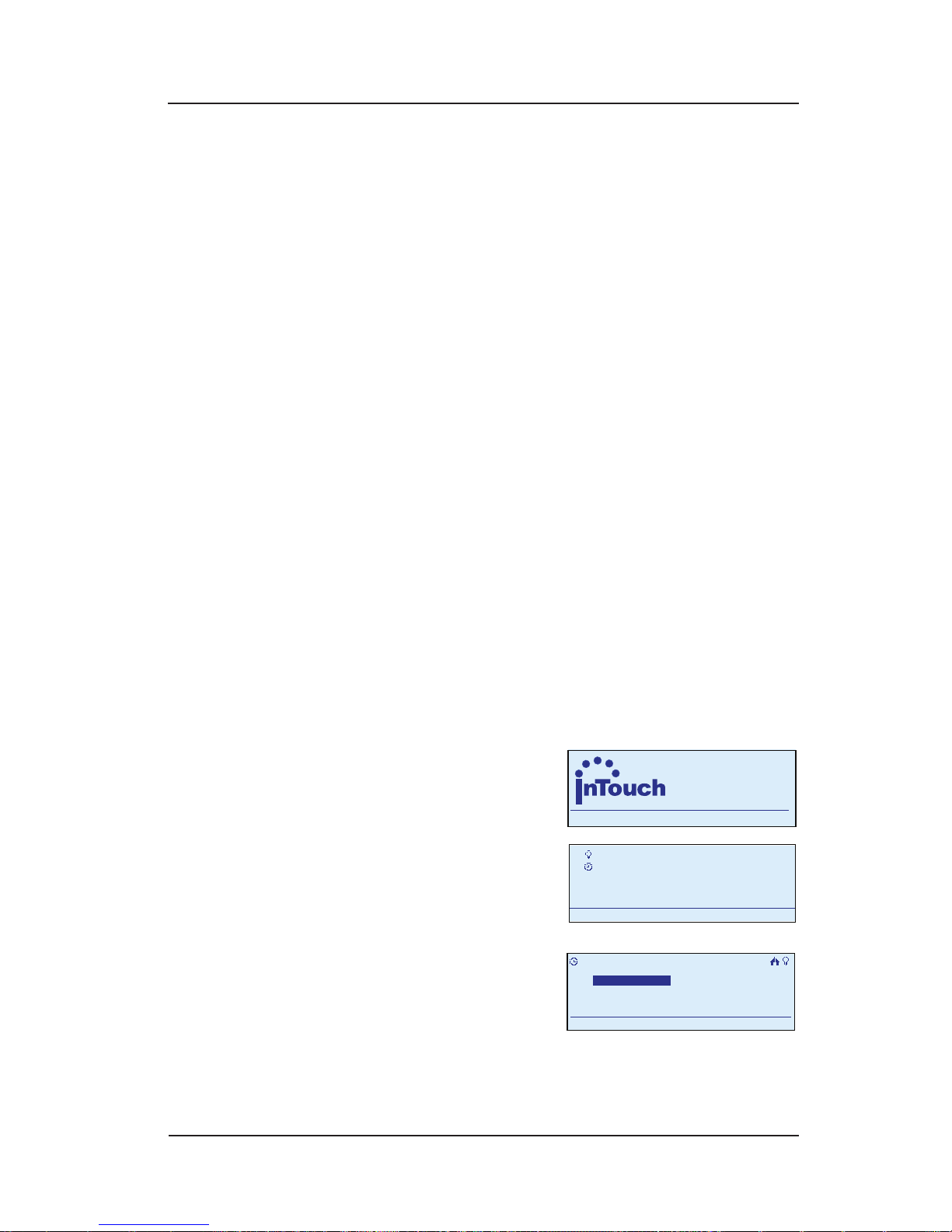
62 InTouch™ User Guide
Copyright © 2006 Intermatic, Inc.
motion sensor could turn on hallway lights to full
brightness in the early evening, and to only 20%
brightness after midnight (so you’re not blinded on
your way to the bathroom).
Setting Up an ON/OFF Recurring Event
A Recurring Event turns a scene ON or OFF, on a
repeating basis, either at:
Specic times
“Astronomically” where the ON/OFF times adjust
automatically according to sunrise and sunset
(earlier sunset in winter, etc.)
This step-by-step procedure will guide you through all
types.
Setting the ON Time
An ON/OFF timer event involves two separate routines:
setting the ON rst, and then setting the OFF.
During programming, use the <ARROW> buttons to
navigate to your selections on the screen. Use the
<RIGHT> arrow to advance to the next item.
NOTE: If you pause for more than 30 seconds during
the programming procedure, the In-Wall Master
Controller will time out and exit programming mode.
.
Begin at the InTouch Home
Screen as shown.
Press <ENTER>. The screen
displays the Main Menu.
Scroll with the <UP/
DOWN> arrows to select
My Events, then press
<ENTER>. The screen
displays options for working with events.
•
•
1.
2.
a
WIRELESS CONTROLS
TM
11:25
a
WIRELESS CONTROLS
TM
11:25
My Scenes
My Events
Setup
11:25a
My Scenes
My Events
Setup
11:25a
My Events
Add Event
Configure Event
Rename Event
11:25a
Delete Event
My Events
Add Event
Configure Event
Rename Event
11:25a
Delete Event
Page 63

Step-by-Step with the In-Wall Master Controller 63
Providing a brighter solution.™
Select Add Event, then
press <ENTER>. The screen
displays the new scene,
giving it a generic name
like “Event 1” and highlighting the rst letter in the
event name (“E” in “Event 1”).
OPTION: You can rename the event to something
that’s more descriptive. If this is the ON setting for
outside lights, you might name it “Outside On.”
To rename the event at this time, follow
instructions below.
To skip renaming at this time, press <ENTER>. The
screen highlights Congure. Continue at Step 6.
Scroll with the <UP/DOWN> arrows to select the rst
character of the new name, then with the <RIGHT>
arrow to select the second character, and continue.
The characters repeat in a loop in the order shown
below, starting from wherever you are at the time.
There is a “blank space” symbol between the “~”
symbol and the “!” symbol, as shown below.
ABCDEFGHIJKLMNOPQRSTUVWXYZ[\]^_`
abcdefghijklmnopqrstuvwxyz{|}~ !
”#$%&’()*+,-./0123456789:;<=>?@
NOTE: To shorten a name or “erase” unwanted
characters, override them with a “blank space”
character.
When you are satised with the new name of
the event, press the <ENTER> button to highlight
Congure.
3.
•
•
4.
5.
>Add Event
Enter Event Name:
Event 1
11:25a
E
Configure>
>Add Event
Enter Event Name:
Event 1
11:25a
E
Configure>
Page 64
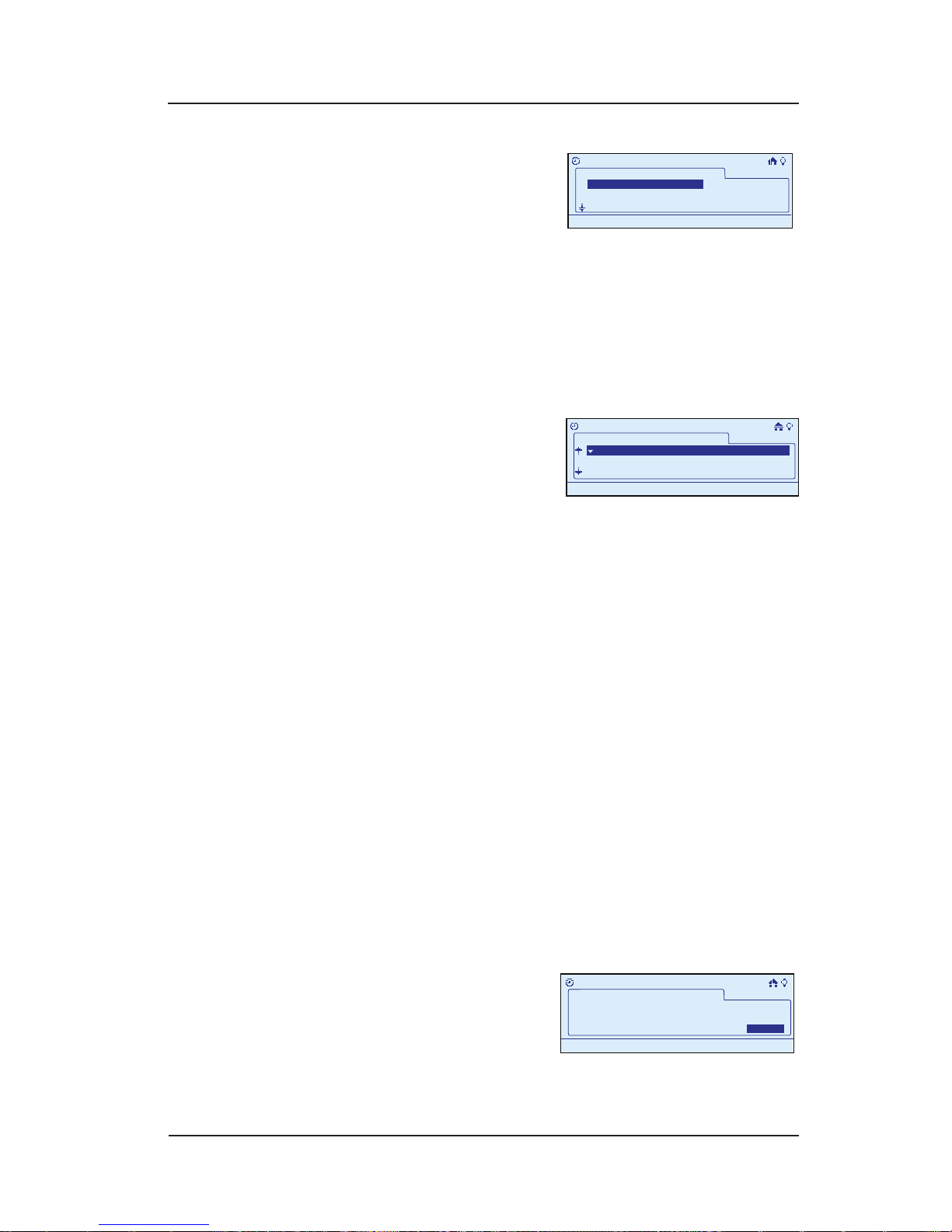
64 InTouch™ User Guide
Copyright © 2006 Intermatic, Inc.
Press <ENTER> again to
congure the event. The
screen displays a list of
all scenes currently in the
network.
Scroll with the <UP/DOWN> arrow buttons to select the
rst scene to be controlled by this event, then press
<ENTER> to place a “+” sign marking the scene.
Repeat Step 7 for other scenes you want to be
controlled by this event.
When nished, press the
<DOWN> arrow button to
advance to the bottom of
the screen to select Next,
then press <ENTER>. The display will show all devices
currently in the network in their room assignments,
along with their preset settings (i.e., ON, OFF, 50%,
or --- [means “it may be added to the scene at this
point”]).
OPTION: Though they’re probably OK, you can
make adjustments at this time to the setting on any of
the devices. Scroll with the <UP/DOWN> arrow buttons
to select the device you want to change, then press
the <RIGHT/LEFT> arrows to adjust the value. You will
have one of three possibilities:
For a switch—ON and OFF.
For a dimmer switch—OFF and a percentage of
ON.
For a switch not in the scene— three dashes (it
may be added to the scene at this point).
Since you’re creating an event that will turn devices
ON, you’re probably going to set everything to ON.
When you are satised
with changes or not
making any, scroll with
the <DOWN> arrow to
advance to the bottom of the screen and highlight
6.
7.
8.
9.
•
•
•
10.
>Configure Event
Event 1
Scene 2
Scene 3
+Scene 1
11:25a
>Configure Event
Event 1
Scene 2
Scene 3
+Scene 1
11:25a
Event 1
Binary Switch 5
Multi Level Switch 3
OFF
75%
Bathroom1
Bathroom 1
>Configure Event
11:25a
Event 1
Binary Switch 5
Multi Level Switch 3
OFF
75%
Bathroom1
Bathroom 1
>Configure Event
11:25a
What is the event duration?
>Configure Event
11:25a
Next>Next>
Event 1
Manual Off
What is the event duration?
>Configure Event
11:25a
Next>Next>
Event 1
Manual Off
Page 65
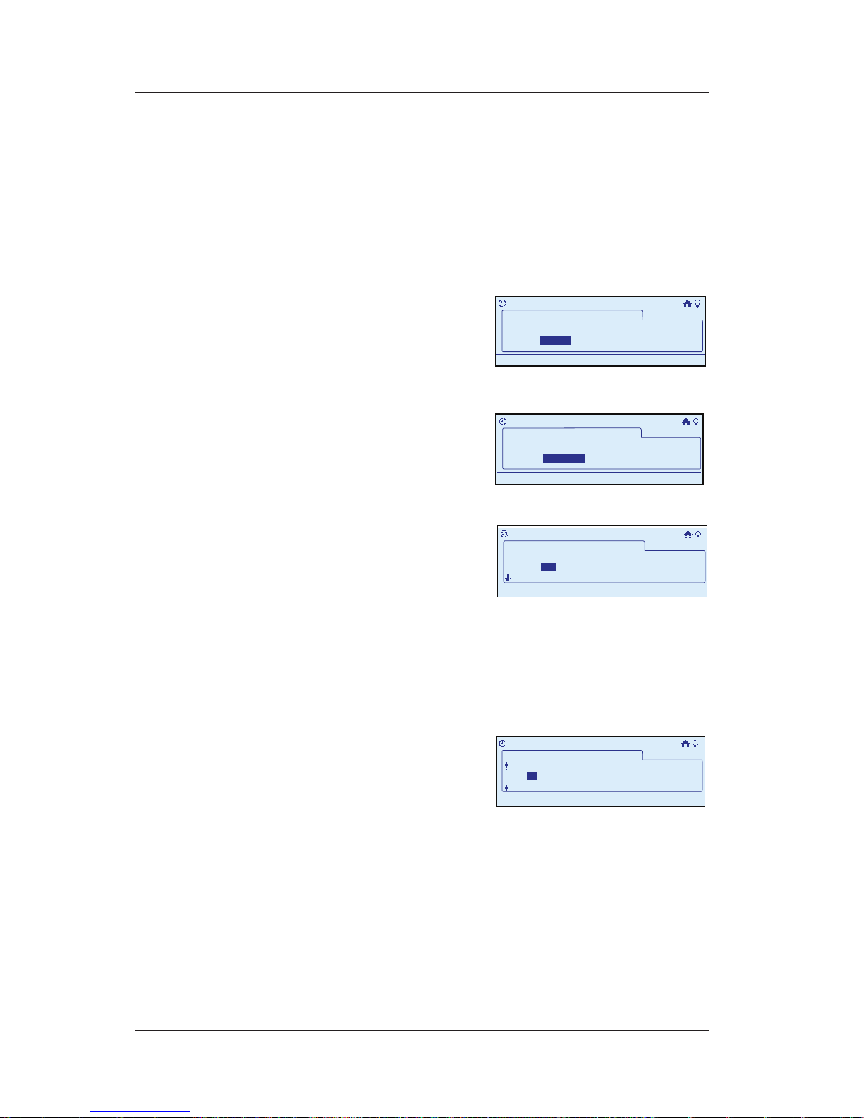
Step-by-Step with the In-Wall Master Controller 65
Providing a brighter solution.™
Next, then press <ENTER>. The screen prompts for
setting the duration of the event.
NOTE: Now you can use the duration setting as a
way to build in an OFF without having to create
another event. You can set a length of time for the
event to stay on of up to 24 hours. See page 69,
Step 11 for instructions if you wish to do this now.
Press the <RIGHT> arrow
to select Next, then press
<ENTER>. The screen
displays options for
activating the event.
Press the <RIGHT> arrow
to select Time, then press
<ENTER>. The screen
requests whether the
event is to be One-Time or Recurring.
Press the <RIGHT> arrow
to select Recurring, then
press <ENTER>. The screen
requests you to specify
the Days you want the event to happen.
Press the <RIGHT> arrow to select the rst Day, then
press <ENTER>. The screen places a “+” sign next to
the day. Repeat the procedure for each day you want
to select.
Press the <RIGHT> arrow
to continue advancing
to the right past Sa
(Saturday). The screen
displays the option to set start time. You can select
for a start time of a Specic Time, at Sunrise, or at
Sunset.
Press the <RIGHT> arrow to make your selection, then
press <ENTER>. The screen places a “+” sign next to
your choice.
11.
12.
13.
14.
15.
16.
>
Configure Event
What begins this Event?
Event 1
Action
Time
11:25a
>
Configure Event
What begins this Event?
Event 1
Action
Time
11:25a
>
Configure Event>Time
When does this event occur?
Event1
RecurringOnetime
11:25a
>
Configure Event>Time
When does this event occur?
Event1
RecurringOnetime
11:25a
>Configure Event>Time
Select days:
Event 1
Set start time:
TuM W Th F SaSu
11:25a
>Configure Event>Time
Select days:
Event 1
Set start time:
TuM W Th F SaSu
11:25a
Set Start Time:
Event 1
:32a+ Sunrise Sunset12
11:25a
Random:
>>Configure Event>Action
Set Start Time:
Event 1
:32a+ Sunrise Sunset12
11:25a
Random:
>>Configure Event>Action
Page 66
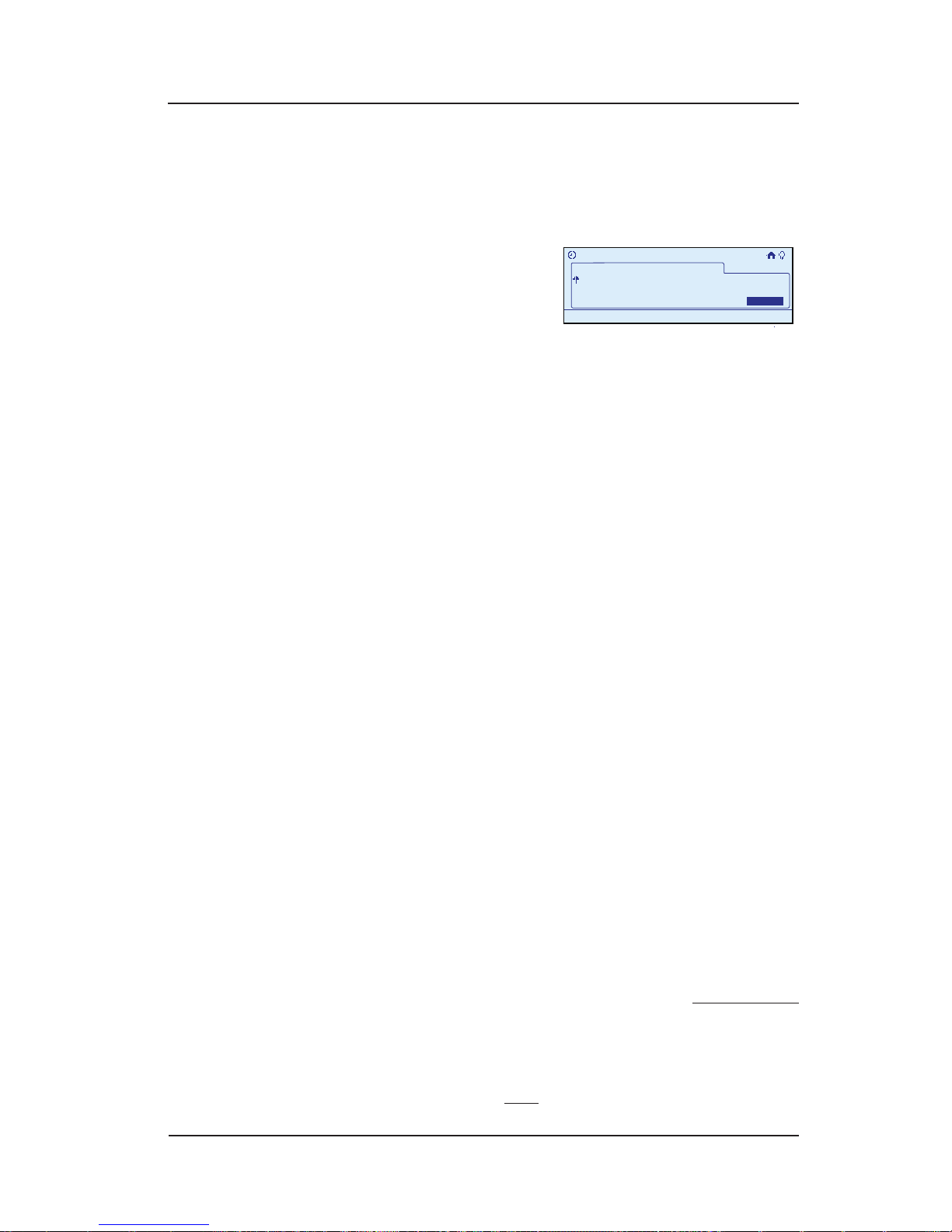
66 InTouch™ User Guide
Copyright © 2006 Intermatic, Inc.
If you are selecting a specic time, scroll with the
<UP/DOWN> arrows to set the correct Hour.
Press the <RIGHT> arrow to select the Minutes eld,
then scroll <UP/DOWN> to set the correct minutes.
When nished setting
start time, press the
<RIGHT> arrow to advance
to the right past Sunset.
The screen displays the option of whether you want
the event to start at a Random time or exact time.
NOTE: If you select Random, the event will occur
within a 30-minute window around the time you
have selected. This is a security feature. If you are
on vacation, choosing Random will make sure your
lights don’t always come on at the same time, giving
your house a “lived in” look.
Scroll with the <UP/DOWN> arrows to turn the
Random feature ON or OFF.
You are now nished. Press the <RIGHT> arrow to
select Done, then press <ENTER>. The display returns
to the Main Menu screen, and automatically exits
programming mode in about 30 seconds if there’s no
activity.
NOTE: A Scene representing the event will be
selected in the scene list and can be edited. This
scene should not be removed unless the associated
event will also be removed.
Setting the OFF Time
You have created the ON time for the event, and must
now go back and create the OFF time for the event. The
procedure is exactly the same. Just keep the following in
mind:
When creating the OFF event, select the same scenes
to be activated (turned off) that you have set in the
ON event. See Steps 7 and 8.
When setting devices, you probably now want the
event to turn them OFF. See Step 9.
17.
18.
19.
20.
21.
•
•
>Configure Event>Time
Random:
Event 1
Off
11:25a
Done>
>Configure Event>Time
Random:
Event 1
Off
11:25a
Done>
Page 67
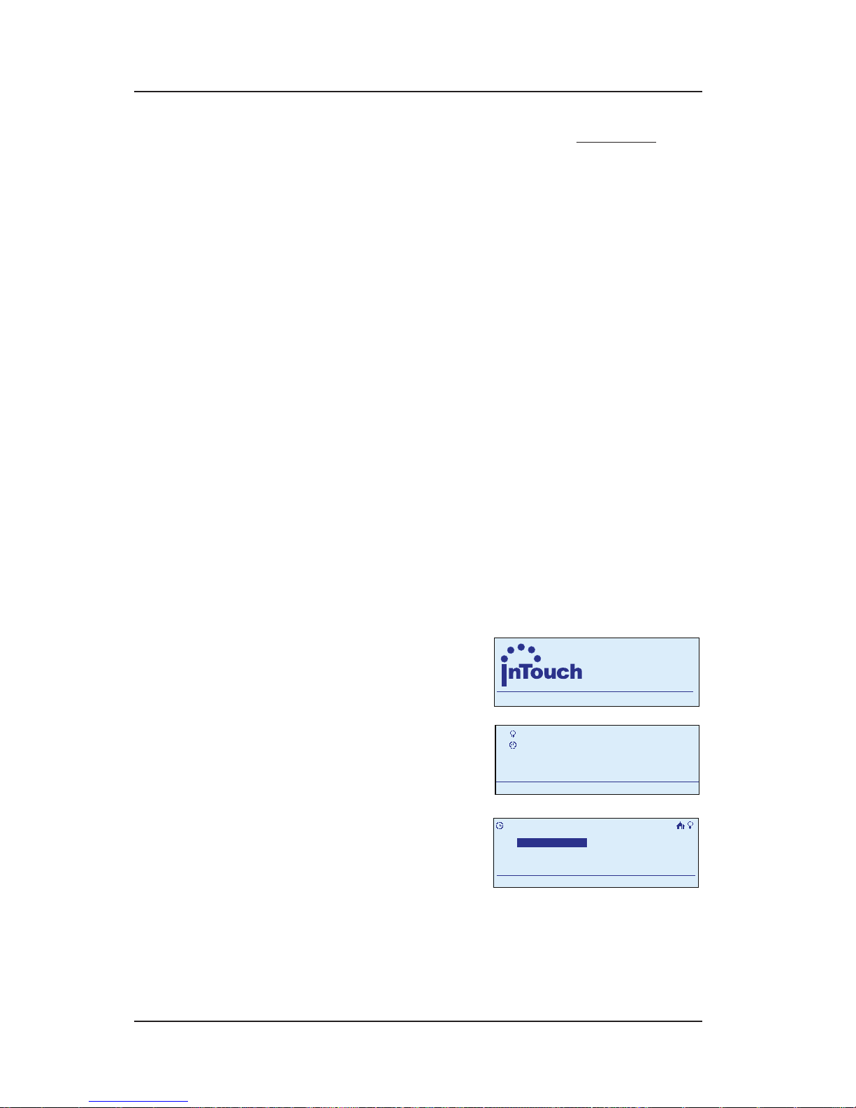
Step-by-Step with the In-Wall Master Controller 67
Providing a brighter solution.™
Be sure your OFF event includes the same days as
the ON event. See Step 14.
Another idea: You can use the duration setting as
a way to build in an OFF without having to create
another event. You can set a length of time for the
event to stay ON of up to 24 hours. See page 76.
That’s it. You can set as many ON/OFF pairs as you
want, activating one or more of the scenes in the
network.
Setting Up a Recurring Event of
Specific Duration
Another kind of Recurring Event turns a scene ON at a
specic time, on a repeating basis, and then turns OFF
after the set duration for the event (up to 24 hours) runs
out.
During programming, use the <ARROW> buttons to
navigate to your selections on the screen. Use the
<RIGHT> arrow to advance to the next item.
NOTE: If you pause for more than 30 seconds during
the programming procedure, the In-Wall Master
Controller will time out and exit programming mode.
.
Begin at the InTouch Home
Screen as shown.
Press <ENTER>. The screen
displays the Main Menu.
Scroll with the <UP/
DOWN> arrows to select
My Events, then press
<ENTER>. The screen
displays options for working with events.
•
•
1.
2.
a
WIRELESS CONTROLS
TM
11:25
a
WIRELESS CONTROLS
TM
11:25
My Scenes
My Events
Setup
11:25a
My Scenes
My Events
Setup
11:25a
My Events
Add Event
Configure Event
Rename Event
11:25a
Delete Event
My Events
Add Event
Configure Event
Rename Event
11:25a
Delete Event
Page 68
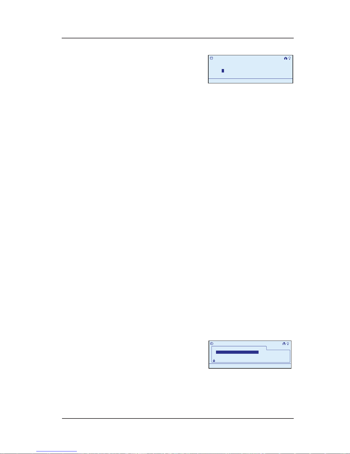
68 InTouch™ User Guide
Copyright © 2006 Intermatic, Inc.
Select Add Event, then
press <ENTER>. The screen
displays the new scene,
giving it a generic name
like “Event 1” and highlighting the rst letter in the
event name (“E” in “Event 1”).
OPTION: You can rename the event to something
that’s more descriptive. If this is the ON setting for
outside lights, you might name it “Outside On.”
To rename the event at this time, follow
instructions below.
To skip renaming at this time, press <ENTER>. The
screen highlights Congure. Continue at Step 6.
Scroll with the <UP/DOWN> arrows to select the rst
character of the new name, then with the <RIGHT>
arrow to select the second character, and continue.
The characters repeat in a loop in the order shown
below, starting from wherever you are at the time.
There is a “blank space” symbol between the “~”
symbol and the “!” symbol, as shown below.
ABCDEFGHIJKLMNOPQRSTUVWXYZ[\]^_`
abcdefghijklmnopqrstuvwxyz{|}~ !
”#$%&’()*+,-./0123456789:;<=>?@
NOTE: To shorten a name or “erase” unwanted
characters, override them with a “blank space”
character.
When you are satised with the new name of
the event, press the <ENTER> button to highlight
Congure.
Press <ENTER> again to
congure the event. The
screen displays a list of
all scenes currently in the
network.
3.
•
•
4.
5.
6.
>Add Event
Enter Event Name:
Event 1
11:25a
E
Configure>
>Add Event
Enter Event Name:
Event 1
11:25a
E
Configure>
>Configure Event
Event 1
Scene 2
Scene 3
+Scene 1
11:25a
>Configure Event
Event 1
Scene 2
Scene 3
+Scene 1
11:25a
Page 69
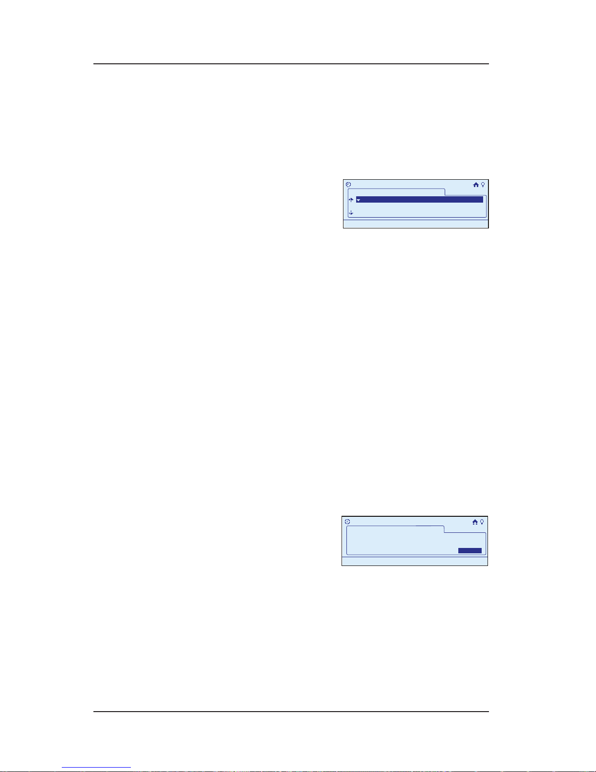
Step-by-Step with the In-Wall Master Controller 69
Providing a brighter solution.™
Scroll with the <UP/DOWN> arrow buttons to select the
rst scene to be controlled by this event, then press
<ENTER> to place a “+” sign marking the scene.
Repeat for other scenes you want to be controlled by
this event.
When nished, press the
<RIGHT> arrow button to
advance to the bottom of
the screen to select Next ,
then press <ENTER>. The display will show all devices
currently in the network, along with their current
settings (i.e., ON, OFF, 50%, or --- [it may be added
to the scene at this point]).
OPTION: You can make adjustments at this time
to the setting on any of the devices. Scroll with
the <UP/DOWN> arrow buttons to select the device
you want to change, then press the <RIGHT/LEFT>
arrows to adjust the value. You will have one of three
possibilities:
For a switch—ON and OFF.
For a dimmer switch—OFF and a percentage of
ON.
For a switch not in the scene— three dashes (it
may be added to the scene at this point).
Since you’re creating an event that will turn lights
ON, you’re probably going to set everything to ON.
When you are satised
with changes or not
making any, scroll with
the <DOWN> arrow to
advance to the bottom of the screen and highlight
Next, then press <ENTER>. The screen prompts for
setting the duration of the event.
Press the <LEFT> arrow to select the hour or minutes,
depending on the duration you want to set (up to 24
hours).
7.
8.
6.
•
•
•
10.
11.
Event 1
Binary Switch 5
Multi Level Switch 3
OFF
75%
Bathroom1
Bathroom 1
>Configure Event
11:25a
Event 1
Binary Switch 5
Multi Level Switch 3
OFF
75%
Bathroom1
Bathroom 1
>Configure Event
11:25a
What is the event duration?
>Configure Event
11:25a
Next>Next>
Event 1
Manual Off
What is the event duration?
>Configure Event
11:25a
Next>Next>
Event 1
Manual Off
Page 70
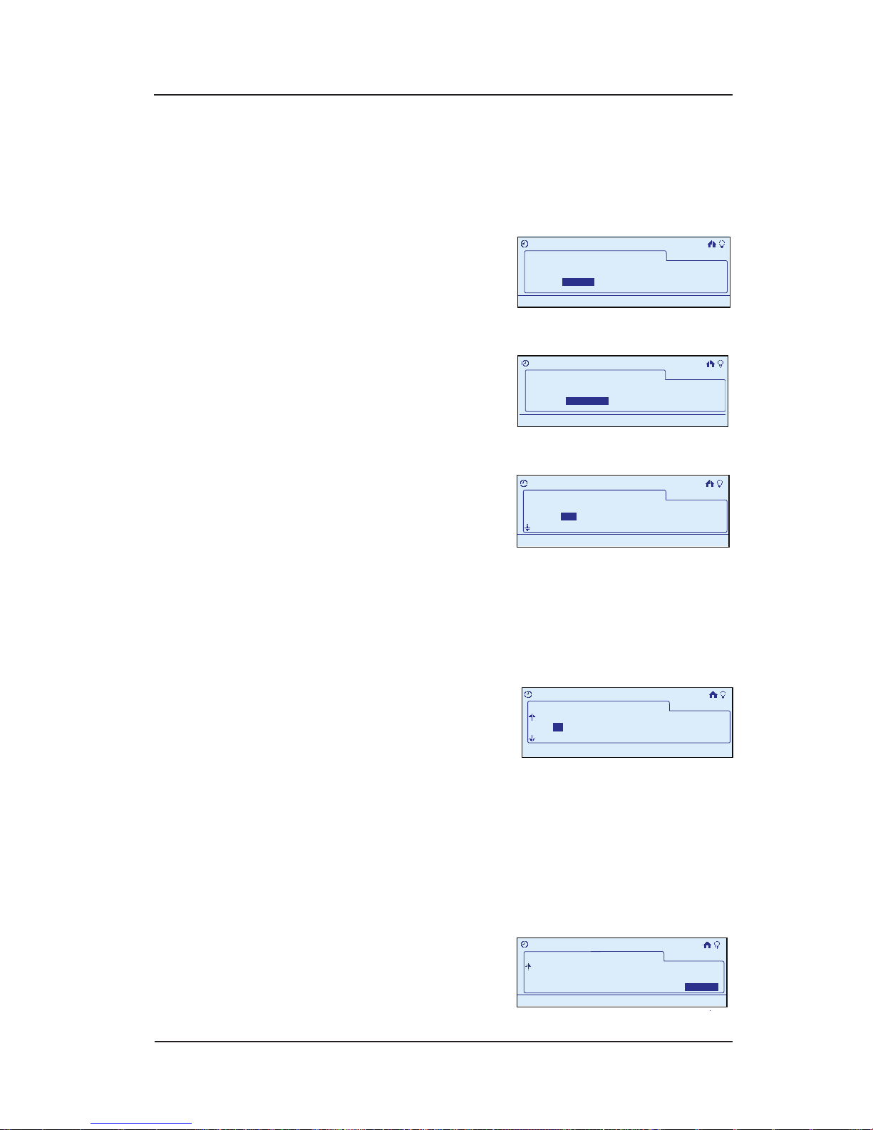
70 InTouch™ User Guide
Copyright © 2006 Intermatic, Inc.
Scroll with the <UP/DOWN> arrow buttons to set the
correct Hour.
Press the <RIGHT> arrow to select the Minutes eld,
then scroll <UP/DOWN> to set the correct minutes.
Press the <RIGHT> arrow
to select Next, then press
<ENTER>. The screen
displays options for
activating the event.
Press the <RIGHT> arrow
to select Time, then press
<ENTER>. The screen
requests whether the
event is to be One-Time or Recurring.
Press the <RIGHT> arrow
to select Recurring, then
press <ENTER>. The screen
requests you to specify
the Days you want the event to happen.
Press the <RIGHT> arrow to select the rst Day, then
press <ENTER>. The screen places a “+” sign next to
the day. Repeat the procedure for each day you want
to select.
Press the <RIGHT> arrow to
continue advancing to the
right past Sa (Saturday).
The screen displays the
option to set start time. You can select for a start time
of a Specic Time, at Sunrise, or at Sunset.
Press the <RIGHT> arrow to make your selection, then
press <ENTER>. The screen places a “+” sign next to
your choice.
If you are selecting a specic time, scroll with the
<UP/DOWN> arrows to set the time you want. As you
get each number correct, press the <RIGHT> arrow to
move to the next number.
12.
13.
10.
11.
16.
17.
18.
19.
20.
>
Configure Event
What begins this Event?
Event 1
Action
Time
11:25a
>
Configure Event
What begins this Event?
Event 1
Action
Time
11:25a
>
Configure Event>Time
When does this event occur?
Event1
RecurringOnetime
11:25a
>
Configure Event>Time
When does this event occur?
Event1
RecurringOnetime
11:25a
>Configure Event>Time
Select days:
Event 1
Set start time:
TuM W Th F SaSu
11:25a
>Configure Event>Time
Select days:
Event 1
Set start time:
TuM W Th F SaSu
11:25a
Set Start Time:
Event 1
:32a+ Sunrise Sunset12
11:25a
Random:
>>Configure Event>Action
Set Start Time:
Event 1
:32a+ Sunrise Sunset12
11:25a
Random:
>>Configure Event>Action
>Configure Event>Time
Random:
Event 1
Off
11:25a
Done>
>Configure Event>Time
Random:
Event 1
Off
11:25a
Done>
Page 71

Step-by-Step with the In-Wall Master Controller 71
Providing a brighter solution.™
When nished setting start time, press the <RIGHT>
arrow to advance to the right past Sunset. The screen
displays the option of whether you want the event to
start at a Random time or exact time.
NOTE: If you select Random, the event will occur
within a 30-minute window around the time you
have selected. This is a security feature. If you are
on vacation, choosing Random will make sure your
lights don’t always come on at the same time, giving
your house a “lived in” look.
Scroll with the <UP/DOWN> arrows to turn the
Random feature ON or OFF.
You are now nished. Press the <RIGHT> arrow to
select Done, then press <ENTER>. The display returns
to the Main Menu screen, and automatically exits
programming mode in about 30 seconds if there’s no
activity.
Setting Up an Action Event
This procedure lets you create an event where the timer
denes the result of the action. For example:
Pressing button #1 in the morning turns on the
kitchen lights and in the evening it turns on the yard
lights. What happens when you press the button is
dened by the timer.
A motion sensor turns on the hallway lights to
full brightness in the early evening, and to 20%
brightness after midnight. In this case, what happens
from the motion-sensor signal depends on the time.
During programming, use the <ARROW> buttons to
navigate to your selections on the screen. Use the
<RIGHT> arrow to advance to the next item.
NOTE: If you pause for more than 30 seconds during
the programming procedure, the In-Wall Master
Controller will time out and exit programming mode.
.
Begin at the InTouch Home
Screen as shown.
21.
22.
23.
•
•
a
WIRELESS CONTROLS
TM
11:25
a
WIRELESS CONTROLS
TM
11:25
Page 72
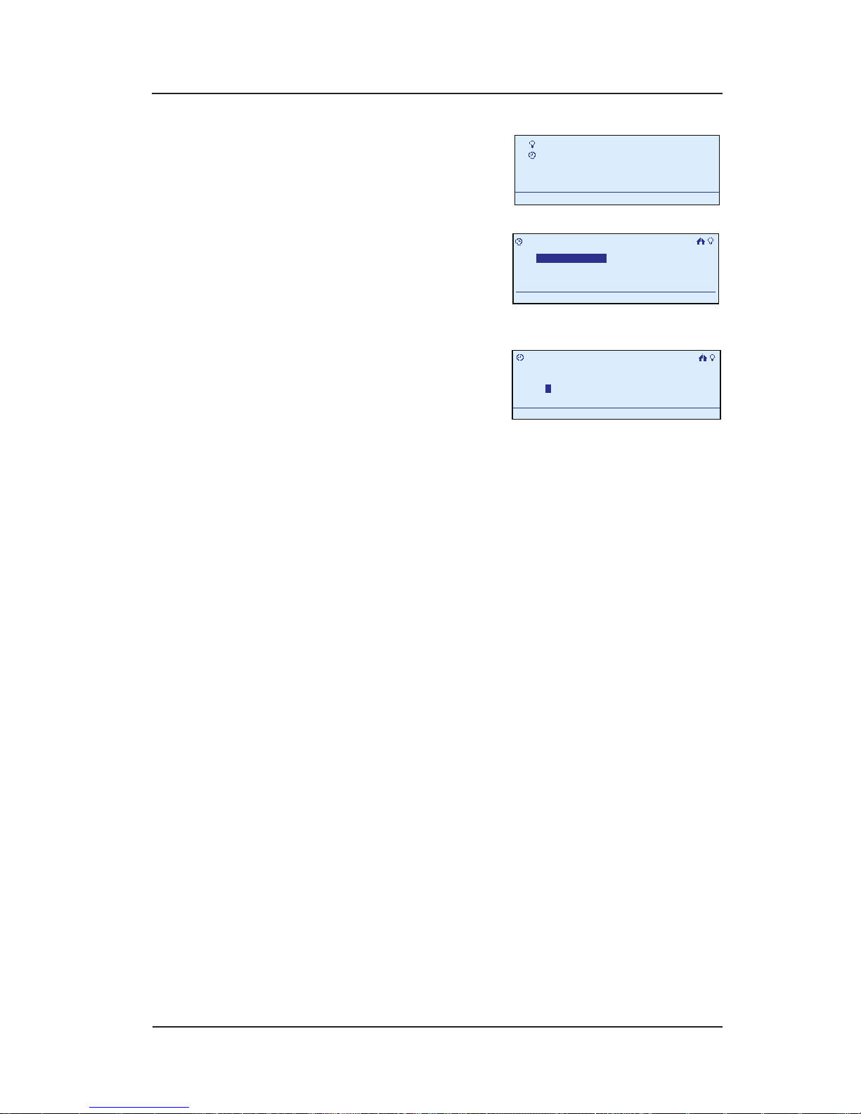
72 InTouch™ User Guide
Copyright © 2006 Intermatic, Inc.
Press <ENTER>. The screen
displays the Main Menu.
Scroll with the <UP/
DOWN> arrows to select
My Events, then press
<ENTER>. The screen
displays options for working with events.
Select Add Event, then
press <ENTER>. The screen
displays the new scene,
giving it a generic name
like “Event 1” and highlighting the rst letter in the
event name (“E” in “Event 1”).
OPTION: You can rename the event to something
that’s more descriptive. If this is the ON setting for
outside lights, you might name it “Outside On.”
To rename the event at this time, follow
instructions below.
To skip renaming at this time, press <ENTER>. The
screen highlights Congure. Continue at Step 6.
Scroll with the <UP/DOWN> arrows to select the rst
character of the new name, then with the <RIGHT>
arrow to select the second character, and continue.
The characters repeat in a loop in the order shown
below, starting from wherever you are at the time.
There is a “blank space” symbol between the “~”
symbol and the “!” symbol, as shown below.
ABCDEFGHIJKLMNOPQRSTUVWXYZ[\]^_`
abcdefghijklmnopqrstuvwxyz{|}~ !
”#$%&’()*+,-./0123456789:;<=>?@
NOTE: To shorten a name or “erase” unwanted
characters, override them with a “blank space”
character.
1.
2.
3.
•
•
4.
My Scenes
My Events
Setup
11:25a
My Scenes
My Events
Setup
11:25a
My Events
Add Event
Configure Event
Rename Event
11:25a
Delete Event
My Events
Add Event
Configure Event
Rename Event
11:25a
Delete Event
>Add Event
Enter Event Name:
Event 1
11:25a
E
Configure>
>Add Event
Enter Event Name:
Event 1
11:25a
E
Configure>
Page 73
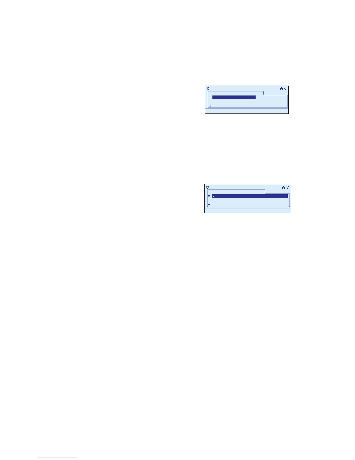
Step-by-Step with the In-Wall Master Controller 73
Providing a brighter solution.™
When you are satised with the new name of
the event, press the <ENTER> button to highlight
Congure.
Press <ENTER> again to
congure the event. The
screen displays a list of
all scenes currently in the
network.
Scroll with the <UP/DOWN> arrow buttons to select the
rst scene to be controlled by this event, then press
<ENTER> to place a “+” sign marking the scene.
Repeat Step 7 for other scenes you want to be
controlled by this event.
When nished, press the
<RIGHT> arrow button to
advance to the bottom of
the screen to select Next,
then press <ENTER>. The display will show all devices
currently in the network, along with their current
settings (i.e., ON, OFF, 50%, or --- [it may be added
to the scene at this point]).
OPTION: You can make adjustments at this time
to the setting on any of the devices. Scroll with
the <UP/DOWN> arrow buttons to select the device
you want to change, then press the <RIGHT/LEFT>
arrows to adjust the value. You will have one of three
possibilities:
For a switch—ON and OFF.
For a dimmer switch—OFF and a percentage of
ON.
For a switch not in the scene— three dashes (it
may be added to the scene at this point).
Since you’re creating an event that will turn lights
ON, you’re probably going to set everything to ON.
5.
6.
7.
8.
9.
•
•
•
>Configure Event
Event 1
Scene 2
Scene 3
+Scene 1
11:25a
>Configure Event
Event 1
Scene 2
Scene 3
+Scene 1
11:25a
Event 1
Binary Switch 5
Multi Level Switch 3
OFF
75%
Bathroom1
Bathroom 1
>Configure Event
11:25a
Event 1
Binary Switch 5
Multi Level Switch 3
OFF
75%
Bathroom1
Bathroom 1
>Configure Event
11:25a
Page 74
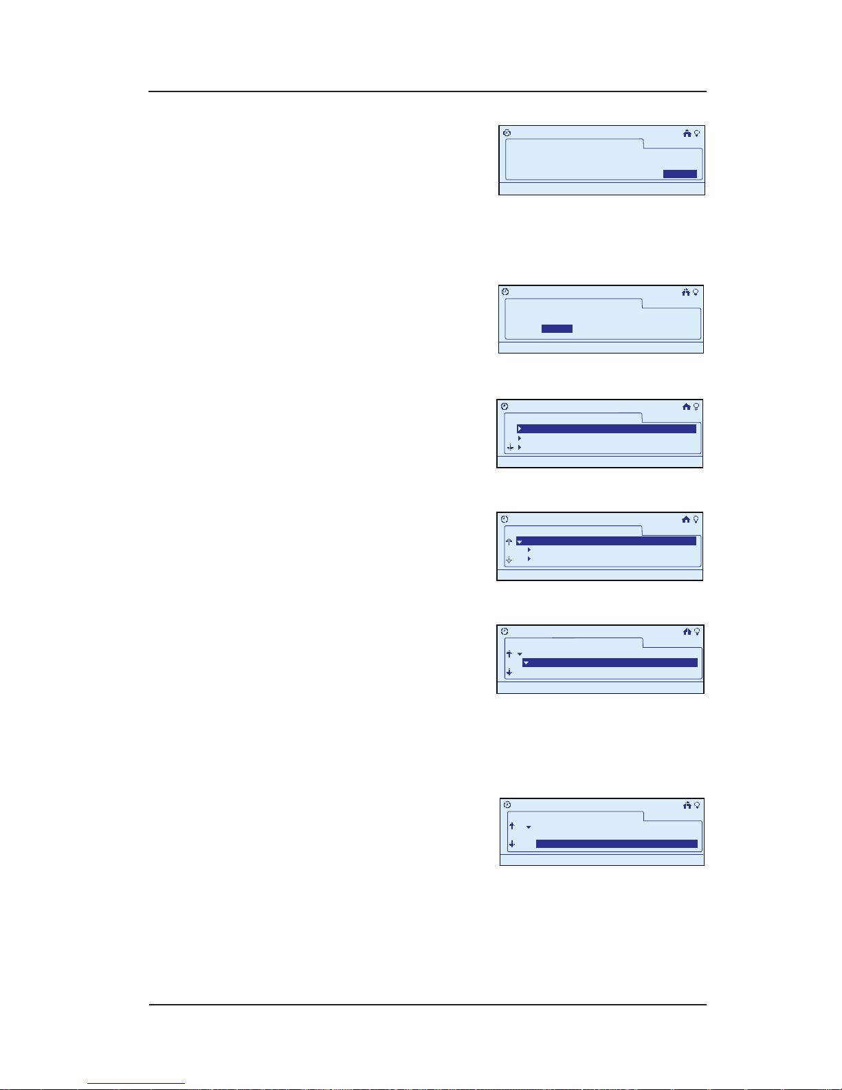
74 InTouch™ User Guide
Copyright © 2006 Intermatic, Inc.
When you are satised
with changes or not
making any, scroll with
the <DOWN> arrow to
advance to the bottom of the screen and highlight
Next, then press <ENTER>. The screen prompts for
setting the duration of the event.
Press the <RIGHT> arrow
to select Next, then press
<ENTER>. The screen
displays options for
activating the event.
Press the <RIGHT> arrow
button to select Action,
then press <ENTER>. The
screen displays the
option to select which room is to be involved.
Scroll to select a room
and press <ENTER>. The
screen displays devices
associated with the
room.
Scroll with the <UP/
DOWN> arrows to
select the device you
want to congure,
then press <ENTER>. The screen displays the input
actions available to trigger the event, for example,
depending on the device, “Input 1” might be the
press of a button, a signal from a motion sensor, etc.
.
Scroll with the <UP/
DOWN> arrows to select
the input action(s) you
want to activate the
event, then press <ENTER>. The screen places a “+”
sign next to your choices.
10.
11.
12.
13.
14.
15.
What is the event duration?
>Configure Event
11:25a
Next>Next>
Event 1
Manual Off
What is the event duration?
>Configure Event
11:25a
Next>Next>
Event 1
Manual Off
>
Configure Event
What begins this Event?
Event 1
Action
Time
11:25a
>
Configure Event
What begins this Event?
Event 1
Action
Time
11:25a
Event 1
>
Configure Event>Action
11:25a
Bathroom 1
Bedroom 1
Bedroom 2
Event 1
>
Configure Event>Action
11:25a
Bathroom 1
Bedroom 1
Bedroom 2
Event 1
>
Configure Event>Action
11:25a
Wall Control 3
PIR Sensor 1
Bathroom1
Bathroom 1
Event 1
>
Configure Event>Action
11:25a
Wall Control 3
PIR Sensor 1
Bathroom1
Bathroom 1
Event 1
>
Configure Event>Action
11:25a
Input 1
Bathroom1
Bathroom 1
Wall Control 3
Event 1
>
Configure Event>Action
11:25a
Input 1
Bathroom1
Bathroom 1
Wall Control 3
Event 1
>
Configure Event>Action
11:25a
Input 1
Wall Control 3
+Input 2
Event 1
>
Configure Event>Action
11:25a
Input 1
Wall Control 3
+Input 2
Page 75
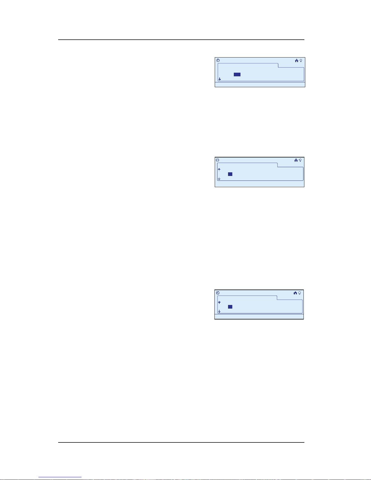
Step-by-Step with the In-Wall Master Controller 75
Providing a brighter solution.™
After selecting all inputs,
scroll with the <DOWN>
arrow to highlight Next,
then press <ENTER>. The
screen requests you to specify the Days you want the
event to happen.
Press the <RIGHT> arrow to select the rst Day, then
press <ENTER>. The screen places a “+” sign next to
the day. Repeat the procedure for each day you want
to select.
Press the <RIGHT> arrow to
continue advancing to the
right past Sa (Saturday).
The screen displays the
option to set the start time. You can select for a start
time of a Specic Time, at Sunrise, or at Sunset.
Press the <RIGHT> arrow to make your selection, then
press <ENTER>. The screen places a “+” sign next to
your choice.
If you are selecting a specic time, scroll with the
<UP/DOWN> arrows to set the time you want. As you
get each number correct, press the <RIGHT> arrow to
move to the next number.
Press the <RIGHT> arrow
to continue advancing
to the right. The screen
displays the option to set
a specic end time.
Scroll with the <UP/DOWN> arrows to set the time
you want. As you get each number correct, press the
<RIGHT> arrow to move to the next number.
When nished setting end time, press the <RIGHT>
arrow to select Done, then press <ENTER>. The display
returns to the Main Menu screen, and automatically
exits programming mode in about 30 seconds if
there’s no activity.
16.
17.
18.
19.
20.
21.
22.
23.
>Configure Event>Action
Select days:
Event 1
Set start time:
TuM W Th F SaSu
11:25a
>Configure Event>Action
Select days:
Event 1
Set start time:
TuM W Th F SaSu
11:25a
>
Set Start Time:
Event 1
:32a+ Sunrise Sunset12
11:25a
>Configure Event>Action
End Time:
>
Set Start Time:
Event 1
:32a+ Sunrise Sunset12
11:25a
>Configure Event>Action
End Time:
>Configure Event>Action
Set End Time:
Event 1
:32a1
11:25a
DONE>
>Configure Event>Action
Set End Time:
Event 1
:32a1
11:25a
DONE>
Page 76
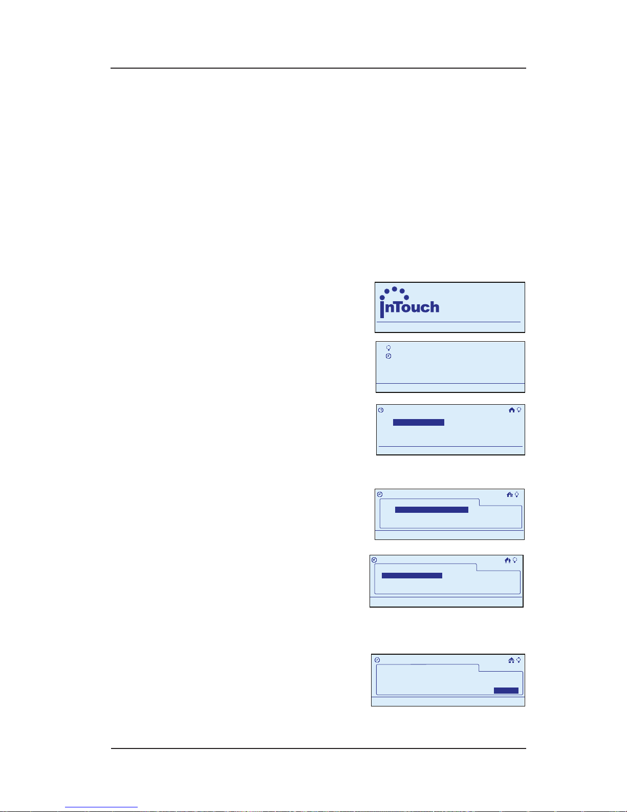
76 InTouch™ User Guide
Copyright © 2006 Intermatic, Inc.
Other Event Programming
Setting the Duration of an Event
This procedure lets you set the length of time an event
will last.
During programming, use the <ARROW> buttons to
navigate to your selections on the screen. Use the
<RIGHT> arrow to advance to the next item.
NOTE: If you pause for more than 30 seconds during
the programming procedure, the In-Wall Master
Controller will time out and exit programming mode.
Begin at the InTouch Home
Screen as shown.
Press <ENTER>. The screen
displays the Main Menu.
Scroll with the <UP/
DOWN> arrows to select
My Events, then press
<ENTER>. The screen
displays event options.
Select Congure Event,
then press <ENTER>. The
screen displays the list of
stored events.
Scroll with the <UP/
DOWN> arrows to select
the event you want to
congure, then press
<ENTER>. The screen displays options for activating
the event.
Select Event Duration,
then press <ENTER>. The
screen species that you
set the duration time for
the event.
1.
2.
3.
4.
5.
a
WIRELESS CONTROLS
TM
11:25
a
WIRELESS CONTROLS
TM
11:25
My Scenes
My Events
Setup
11:25a
My Scenes
My Events
Setup
11:25a
My Events
Add Event
Configure Event
Rename Event
11:25a
Delete Event
My Events
Add Event
Configure Event
Rename Event
11:25a
Delete Event
>Configure Event
My Events
Event 2
Event 1
11:25a
>Configure Event
My Events
Event 2
Event 1
11:25a
Event 1
>
Configure Event
11:25a
Event Scene
Time/Action
Event duration
Event 1
>
Configure Event
11:25a
Event Scene
Time/Action
Event duration
What is the event duration?
>Configure Event
11:25a
Next>Next>
Event 1
Manual Off
What is the event duration?
>Configure Event
11:25a
Next>Next>
Event 1
Manual Off
Page 77
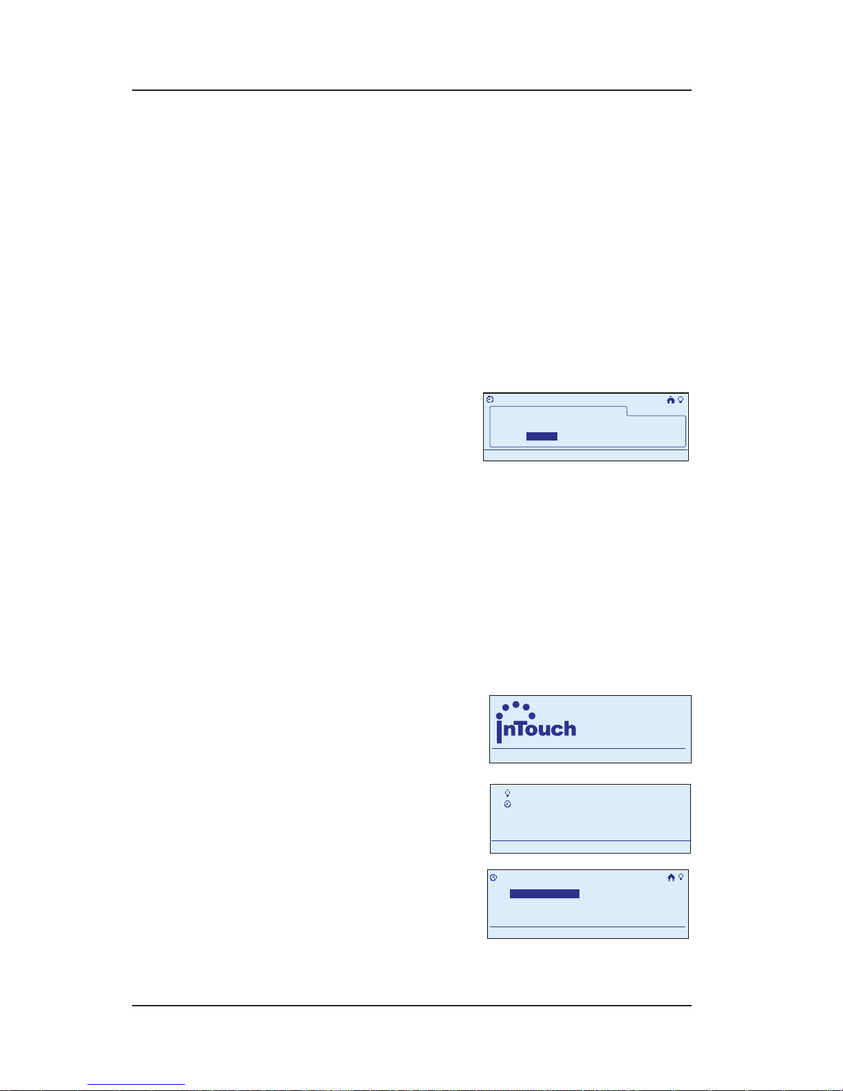
Step-by-Step with the In-Wall Master Controller 77
Providing a brighter solution.™
NOTE: If you scroll below one minute, the screen
displays Manual Off. This means the event will turn
something on, but you will have to manually turn it
off.
Press the <LEFT> arrow to select the hour or minutes,
depending on the duration you want to set (up to 24
hours).
Scroll with the <UP/DOWN> arrow buttons to set the
correct Hour.
Press the <RIGHT> arrow to select the Minutes eld,
then scroll <UP/DOWN> to set the correct minutes.
You are now nished.
Press the <RIGHT> arrow
to select Next, then press
<ENTER>.
Continue at page 65, Step 12 for a Time Event.
Continue at page 74, Step 12 for an Action Event.
Renaming an Event
During programming, use the <ARROW> buttons to
navigate to your selections on the screen. Use the
<RIGHT> arrow to advance to the next item.
NOTE: If you pause for more than 30 seconds during
the programming procedure, the In-Wall Master
Controller will time out and
exit programming mode.
Begin at the InTouch Home
Screen as shown.
Press <ENTER>. The screen
displays the Main Menu.
Scroll with the <UP/
DOWN> arrows to select
My Events, then press
<ENTER>. The screen
displays options for working with events.
6.
7.
8.
9.
•
•
1.
2.
>
Configure Event
What begins this Event?
Event 1
Action
Time
11:25a
>
Configure Event
What begins this Event?
Event 1
Action
Time
11:25a
a
WIRELESS CONTROLS
TM
11:25
a
WIRELESS CONTROLS
TM
11:25
My Scenes
My Events
Setup
11:25a
My Scenes
My Events
Setup
11:25a
My Events
Add Event
Configure Event
Rename Event
11:25a
Delete Event
My Events
Add Event
Configure Event
Rename Event
11:25a
Delete Event
Page 78
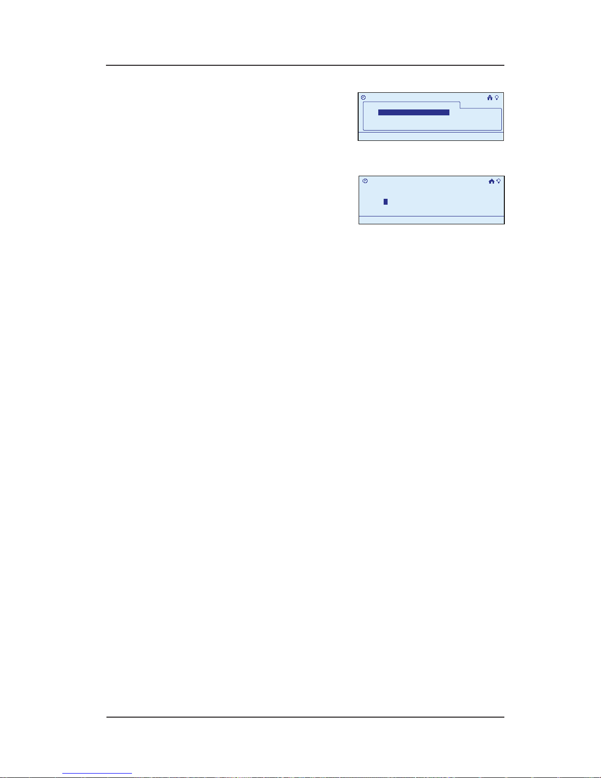
78 InTouch™ User Guide
Copyright © 2006 Intermatic, Inc.
Select Rename Event,
then press <ENTER>. The
screen displays a list of
the events programmed in
your system.
Select the event you want
to rename and press
<ENTER>. The rst letter of
the existing event name
(“E” in “Event 1”) is highlighted.
Scroll with the <UP/DOWN> arrows to select the rst
character of the new name, then with the <RIGHT>
arrow to select the second character, and continue.
The characters repeat in a loop in the order shown
below, starting from wherever you are at the time.
There is a “blank space” symbol between the “~”
symbol and the “!” symbol, as shown below.
ABCDEFGHIJKLMNOPQRSTUVWXYZ[\]^_`
abcdefghijklmnopqrstuvwxyz{|}~ !
”#$%&’()*+,-./0123456789:;<=>?@
NOTE: To shorten a name or “erase” unwanted
characters, override them with a “blank space”
character.
When you are satised with the new name of the
event, press the <ENTER> button to highlight Save
& Close, then press <ENTER> again to complete the
procedure. The display returns to the programming
screen, and automatically exits programming mode
in about 30 seconds if there’s no activity.
3.
4.
5.
6.
>Rename Event
11:25a
My Events
Event 2
Event 1
>Rename Event
11:25a
My Events
Event 2
Event 1
>Rename Event
11:25a
Enter Event Name
Event 1
Save & Close
>Rename Event
11:25a
Enter Event Name
Event 1
Save & Close
Page 79
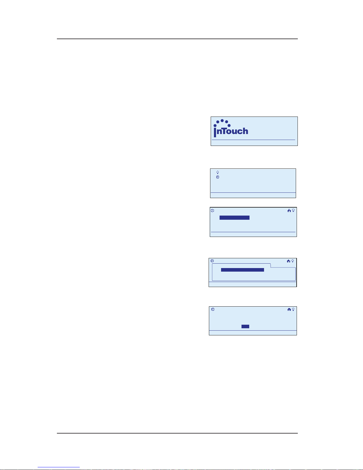
Troubleshooting 79
Providing a brighter solution.™
Deleting an Event
During programming, use the <ARROW> buttons to
navigate to your selections on the screen. Use the
<RIGHT> arrow to advance to the next screen.
NOTE: If you pause for more than 30 seconds during
the programming procedure, the In-Wall Master
Controller will time out and
exit programming mode.
Begin at the InTouch Home
Screen as shown.
Press <ENTER>. The screen
displays the Main Menu.
Scroll with the <UP/
DOWN> arrows to select
My Events, then press
<ENTER>. The screen
displays options for working with events.
Select Delete Event,
then press <ENTER>. The
screen displays a list of
the events programmed
in your system.
Select the event you
want to delete and press
<ENTER>. The screen
requests conrmation
before it will delete the event.
Press the <RIGHT/LEFT> arrows to select Yes, then press
<ENTER>. The system deletes the event. The display
returns to the Main Menu screen, and automatically
exits programming mode in about 30 seconds if
there’s no activity.
1.
2.
3.
4.
5.
a
WIRELESS CONTROLS
TM
11:25
a
WIRELESS CONTROLS
TM
11:25
My Scenes
My Events
Setup
11:25a
My Scenes
My Events
Setup
11:25a
My Events
Add Event
Configure Event
Rename Event
11:25a
Delete Event
My Events
Add Event
Configure Event
Rename Event
11:25a
Delete Event
>Delete Event
11:25a
My Events
Event 2
Event 1
>Delete Event
11:25a
My Events
Event 2
Event 1
>Delete Event
Remove Event 1
11:25a
Save & Close
No Yes
>Delete Event
Remove Event 1
11:25a
Save & Close
No Yes
Page 80

80 InTouch™ User Guide
Copyright © 2006 Intermatic, Inc.
Section 6:
Troubleshooting
Issue Possible Solution
The Status Light on
the Hand-Held stays
lit after the include
process nishes.
Remove and reinsert the battery.
Place the Hand-Held into the Base.
Remove the device from the network,
then re-include it.
1.
2.
3.
The Hand-Held or
base will not reset.
Insert the Hand-Held into Base.
Disconnect the power supply for the
Base.
Wait 10 seconds.
Reconnect the power supply.
Try again.
1.
2.
3.
4.
5.
An In-Wall Scene/
Group Controller
or In-Wall Master
Controller will not
reset.
Disconnect the power at the fuse or
breaker.
Wait 10 seconds.
Reconnect the power.
Try again.
1.
2.
3.
4.
The Status Light on
the Base just blinks
RED when no HandHeld is present.
Disconnect the power supply for the
Base.
Wait 10 seconds.
Reconnect the power supply.
Try again. If this does not solve the
problem, contact Intermatic Customer
Service.
1.
2.
3.
4.
Base light just blinks
RED when a HandHeld is inserted.
There is no connection. Try removing
the Hand-Held and reinserting it.
The battery is overcharged. Wait for a
few minutes and try again.
The battery has discharged excessively.
Call Intermatic Customer Service to
order a new battery.
•
•
•
Page 81

Troubleshooting 81
Providing a brighter solution.™
Issue Possible Solution
The Hand-Held falls
asleep while setting
up a scene.
This is normal behavior.
Finish setting up the scene.
Press the <HOME> button to wake the
Hand-Held.
Press and hold the <SCENE SELECTION>
button to complete the setup.
1.
2.
3.
Device does
not respond to
commands from the
Hand-Held.
Exclude and re-include the device.
NOTE: The CA5100 cannot be controlled
by remote.
A scene used to work,
but no longer controls
devices.
Recreate the scene.
Creating a new scene overwrites the
previous scene.
The Hand-Held or Base may be out of
range of the devices to be controlled.
Include additional devices to the network
to expand its range.
Scene creation causes
a RED light error.
No devices were included in the scene,
so the scene was erased.
Try excluding and re-including all
devices in the scene to make sure they
are in the network.
Another device may already be in
“learn” mode.
Make sure that the Hand-Held is
included to the Base before using it in
the network.
The Base may be out of range of the
devices to be controlled. Include
additional devices to the network to
expand its range.
NOTE: The CA5100 cannot be controlled
by remote.
•
•
•
•
•
Page 82

82 InTouch™ User Guide
Copyright © 2006 Intermatic, Inc.
Issue Possible Solution
The Hand-Held
cannot “include”
devices.
Make sure that the Hand-Held is
“included” to the Base before using it in
the network.
The Hand-Held or Base may be out of
range of the devices to be controlled.
Make sure the Hand-Held is within a
few feet of the device.
The Base may be out of range of the
devices to be controlled. Include
additional devices to the network to
expand its range.
Exclude the device and try again.
•
•
•
•
 Loading...