

Page 1

Before Inst
alling
1. Check the parts in both packages against the Parts Lists shown above. Contact Intermatic if parts are missing.
2. It is suggested that you read these instructions completely before installing the Stand Alone Protection (SAP) unit.
Note: These modules rely on a good ground connection to function properly. Ground availability
should be a consideration when selecting an installation location.
Do not install Protection Devices during Electrical Storms.
INSTALLATION INSTRUCTIONS
Telephone Indoor Stand Alone Protection
Flush Installation
Model Numbers: Description:
IG2TM 2-line telephone protector with indoor enclosure (NEMA 1)
IG4TM 4-line telephone protector with indoor enclosure (NEMA 1)
Optional Modules
IG2T 2-phone line protection module
Models
SURGE PROTECTION
Description
Quantity Reference
Mounting Frame 1 A
Cover / Back plate 1 B
IG2T (in Model IG2TM) 1 C
IG2T (2nd module in Model IG4TM) 1 D
Screws-self threading (3/8” Torx T20 / slot head) 2 E
Ground Wire 1 F
3/4” x 6 Pan Head Screws (
not shown )4
3/4” anchors (
not shown
)4
Description
Quantity Reference
Flush Mount Cover Plate 1 H
Mounting Bracket 1 J
Screws-self threading (3/8” Torx T20 / slot head) 4 K (Fig.4)
Screws-self threading (5/8” Torx T20 / slot head) 2 L
3/4” x 6 Pan Head Screws (
not shown )4
Parts List
Additional Parts
Flush Mount Kit
A
A
C
D
H
J
F
E
E
B
B
Flat head screw driver, Torx head
screw driver, Awl or hole punch, drill,
1/8” and 3/16” bits.
Tools Required
Notes:
1. Telephone protection is compatible with
Voice and Fax lines, Modem lines and
DSL (Digital Subscriber Lines.)
2. Coaxial protection is compatible with
Local antenna, Cable/Satellite and
Cable Internet lines.
Figure 2
Figure 1
L
Page 2
1. Remove the Cover (B) from the Stand Alone Protector (SAP) unit by removing the two Torx Head screws (F)
and separating the cover from the mounting frame (A).
2. Remove the IG2T phone module from the Mounting Frame by removing the two screws that secure it to the
Mounting Frame.
3. Remove the second IG2T phone module in the same manner if you have Model IG4TM.
4. Invert the Mounting Frame so that it appears similar to the illustration in Figure 2.
5. Reattach the IG2T phone module(s) to the Mounting Frame so that the components face forward.
6. Attach the Cover (B) that was removed in step 1 to the Mounting Frame. The Cover should be secured to the
Mounting Frame in the same manner that it was before step 1 above. The Cover now becomes the Back Plate of
the Stand Alone Protection unit. Refer to Figure 2.
7. Select a location to install the SAP that is convenient to telephone and /or coaxial cables. Allow enough room to
route the cables in and out of the unit. REMEMBER:
THE GROUND CONDUCTOR MUST BE BONDED
(COMMON) WITH THE SERVICE ENTRANCE GROUND.
8. If the SAP is being installed in an existing wall or surface for phone-line protection, continue with step A1 below.
If the SAP is being used in a New building or Prewire installation for phone-line protection, go to SECTION B.
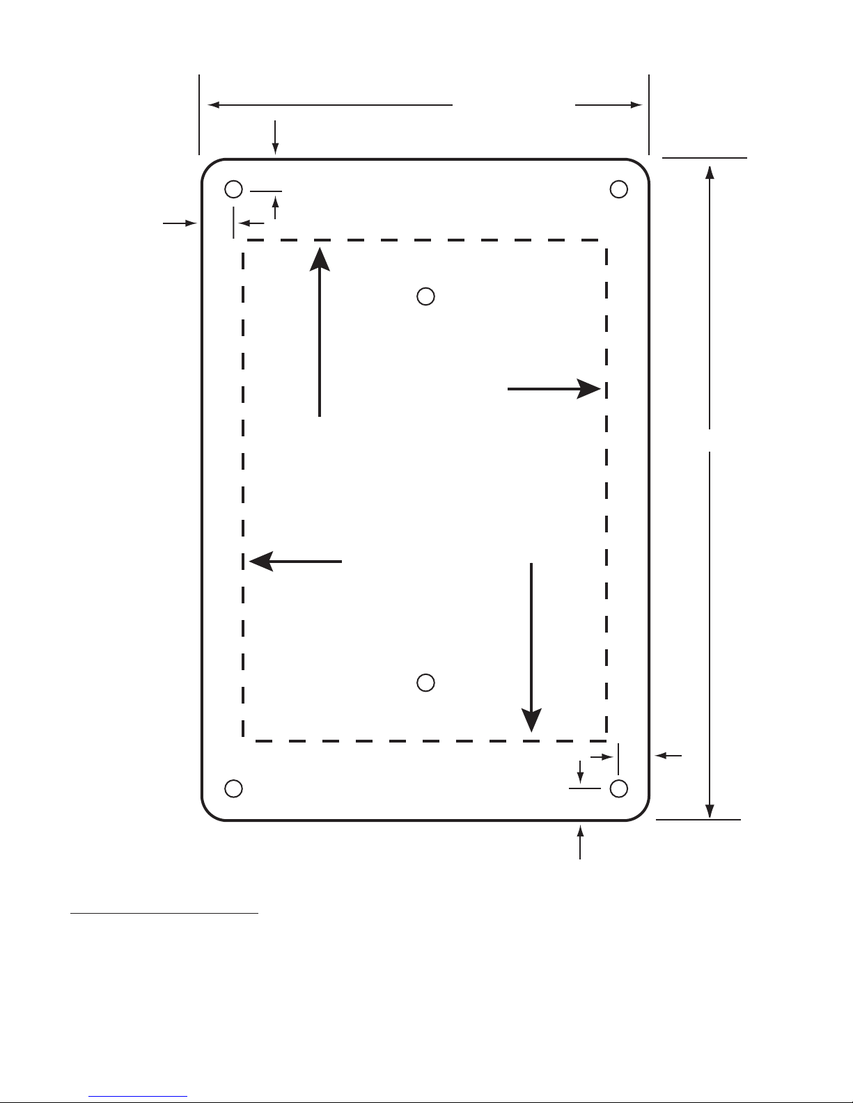
A1. Position the Cutting Template on the wall and mark the recommended cut-out and mounting hole positions.
A2. Cut and remove the recommended area. Drill or punch the holes required to mount the SAP to the wall. If the
3/4” anchors are to be used, insert them into the proper holes in the wall at this time.
A3. Route the phone cables to the SAP and insert each cable through one of the openings. Note that at this point,
the SAP has not been secured to the wall.
A4. Install the Ground Wire and make certain that it is properly connected to the building ground. Use at least 12
gauge wire if additional length is required.
A5. Allow approximately four inches (4”) of phone cable for each connection set. Leave enough slack in the cable to
allow it to be secured to the Mounting Frame without placing stress on the wires and terminals. Route the incoming phone cable (unprotected) to the top of the unit (note the IN on the phone protection module). Route the
protected phone cable to the bottom of the unit (note the OUT on the phone protection module). Secure the
phone cables to the SAP using ty-wraps through one of the unused holes.
A6. Remove 1 inch (1”) of jacket from both phone cables.
Exercise caution when removing the jacket to prevent
nicking the individual wires.
A7. Identify the pairs of wires to be protected and strip one-
quarter inch (1/4”) of insulation from each wire in both
the IN and OUT phone wires. Exercise caution when
removing the insulation to prevent nicking the individual wires.
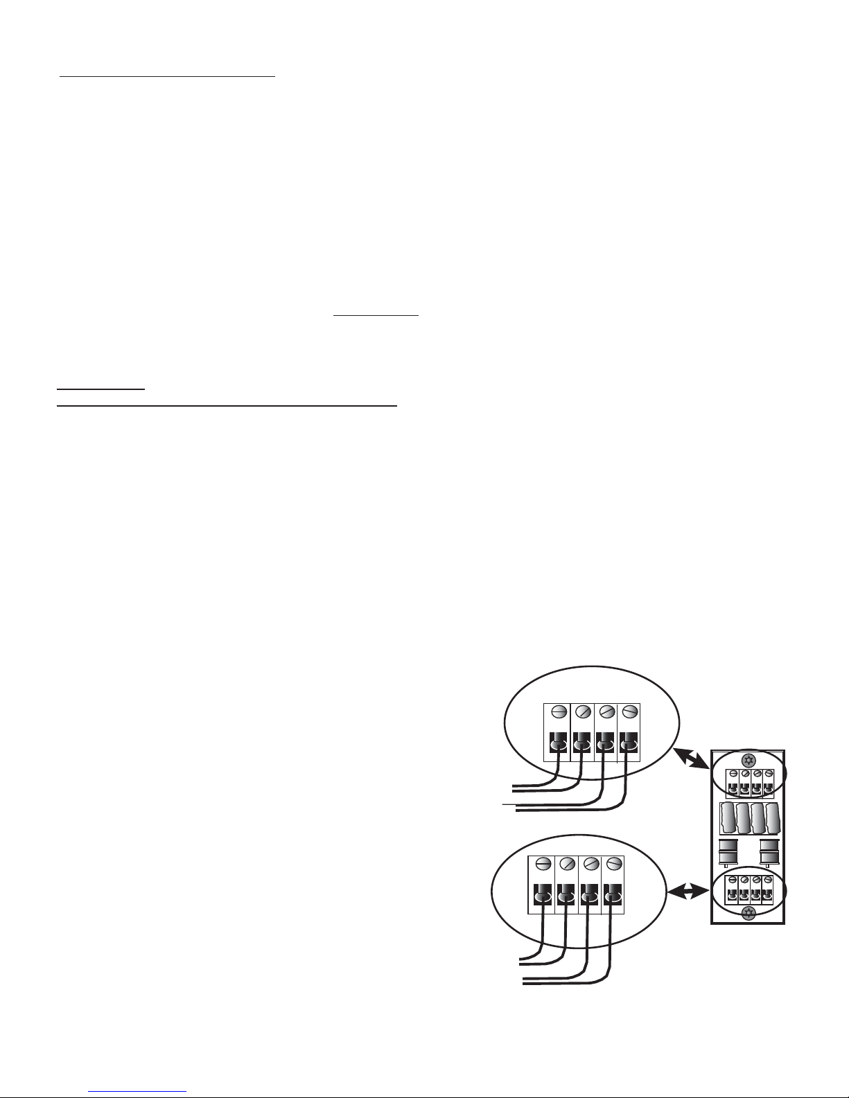
A7. Insert the first pair of wires into the first two positions in
terminal strip marked CN1 located at the IN side of the
protection module. Secure the wires by tightening the
screw in the head of the terminal. Do not overtighten.
The wires are secure if a gentle pull on the wire does
not dislodge it from the terminal. Refer to Figure 3.
A8. Locate the identical pair of wires by color marking in the
cable at the OUT or PROTECTED side of the protection
module and insert and secure them into the first two
positions in terminal strip marked CN3. Be sure to
match the polarity (wire markings) of the pair of wires
connected to terminal strip CN1.
A9. Repeat steps 8 through 10 for each line (pair of wires)
using successive positions in terminal strips CN1 and
CN2 for input and CN3 and CN4 for output.
SECTION A:
Existing or Retro-fit Installations - Telephone Lines
TELEPHONE LINE PROTECTION
1st pair IN
2nd pair IN
1st pair OUT
2nd pair OUT
Figure 3
IN IN
CN1 CN2
IN IN
CN1 CN2
CN3
OUT OUT
CN4
CN3 CN4
OUT OUT
Page 3
A10. Position all unused wires away from the protection module to prevent shorting. Unused wires may be cut off if
additional phone lines are not anticipated in the future.
A11. TEST each phone line for proper operation.
A12. When all wiring is complete, place the Flush Mount Cover Plate on the Mounting Frame and secure it with two (2)
5/8” self threading screws (L).
A13. Align the holes in Flush Mount Cover Plate with the holes or anchors in the wall and secure it to the wall.
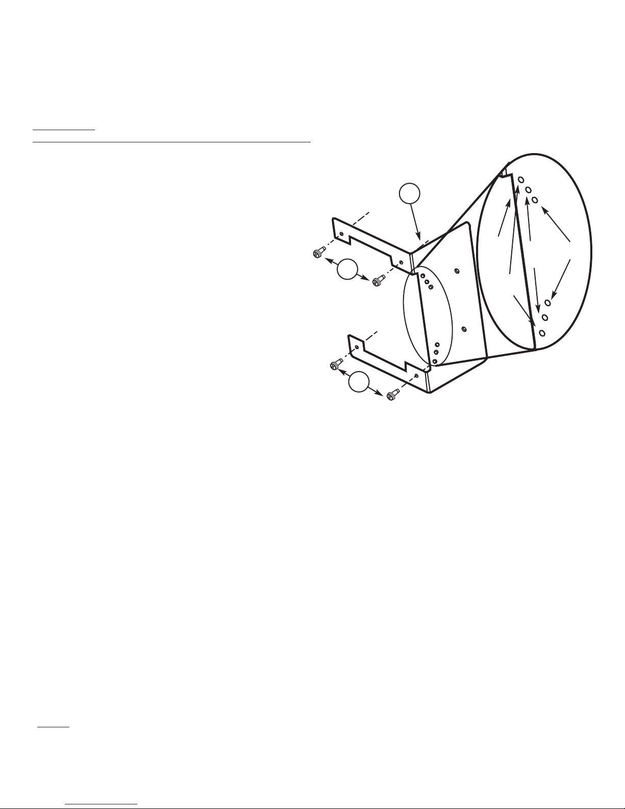
B1. Position the Mounting Bracket (J) on an exposed stud
and secure it to the stud. Use the alignment holes in
the Bracket to compensate for the added thickness of
drywall or wall board and plaster. Note: mounting the
edge of the bracket even with the edge of the stud will
position the unit correctly for 3/8” drywall. Use the
alignment holes for other wall thicknesses.
B2. Secure the reassembled Mounting Frame (A) and Back
Cover (B) to the Mounting Bracket using the self
threading screws (K). Refer to Figures 2 and 4.
B3. Route the phone cables to the SAP and insert each
cable through one of the openings.
B4. Install the Ground Wire and make certain that it is
properly connected to the building ground. Note that a
12 gauge wire should be the minimum size used.
B5. Allow approximately four inches (4”) of phone cable for
each connection set. Leave enough slack in the cable
to allow it to be secured to the Mounting Frame without
placing stress on the wires and terminals. Route the
incoming phone cable (unprotected) to the top of the
unit (note the IN on the phone protection module). Route the protected phone cable to the bottom of the unit (note
the OUT on the phone protection module). Secure the phone cables to the SAP using ty-wraps through one of the
unused holes.
B6. Remove 1 inch (1”) of jacket from both phone cables. Exercise caution when removing the jacket to prevent nicking
the individual wires.
B7. Identify the pairs of wires to be protected and strip one-quarter inch (1/4”) of insulation from each wire in both the IN
and OUT phone wires. Exercise caution when removing the insulation to prevent nicking the individual wires.
B8. Insert the first pair of wires into the first two positions in terminal strip marked CN1 located at the IN side of the pro-
tection module. Secure the wires by tightening the screw in the head of the terminal. Do not overtighten. The wires
are secure if a gentle pull on the wire does not dislodge it from the terminal. Refer to Figure 3.
B9. Locate the identical pair of wires by color marking in the cable at the OUT or PROTECTED side of the protection
module and insert and secure them into the first two positions in terminal strip marked CN3. Be sure to match the
polarity (wire markings) of the pair of wires connected to terminal strip CN1.
B10. Repeat steps 8 through 10 for each line (pair of wires) using successive positions in terminal strips CN1 and CN2
for input and CN3 and CN4 for output.
B11. Position all unused wires away from the protection module to prevent shorting. Unused wires may be cut off if
additional phone lines are not anticipated in the future.
B12. TEST each phone line for proper operation.
B13. When all wiring is complete, place the Flush Mount Cover Plate on the Mounting Frame and secure it with two (2)
5/8” self threading screws (L).
B14. Align the holes in Flush Mount Cover Plate with the holes or anchors in the wall and secure it to the wall.
SECTION B:
New Building and Prewire Installations - Telephone Lines
3/8”
1/2”
3/4”
5/8”
K
K
Alignment Holes
Figure 4
NOTE:
In the event that the Telephone surge protection circuit should fail due to excessive energy, it may result in an “OFF HOOK” condition
for telephone lines. The protector should be bypassed until a replacement unit is obtained and installed.
For troubleshooting assistance, call Intermatic at 1-800-391-4555.
J
Page 4
INTERMATIC INCORPORATED
Spring Grove, Illinois 60081
http://www.intermatic.com
158IG12080
4.46” ( 29/64 )
6.60” ( 19/32 )
5/16”
5/16”
5/16”
5/16”
CUT OUT AREA
INSIDE OF
DASHED LINE
FLUSH MOUNT COVER PLATE
Model Number IGFLUSH
(ordered separately)
INSTALLATION NOTES:
This plate may be installed in the Vertical or Horizontal position. Position this template over the
surface and mark the cut-out area through the template. Carefully cut out the marked area.
CUTTING TEMPLATE
 Loading...