

Page 1

Spring Grove, Illinois 60081
www.intermatic.com
ICUBE™ Adaptive Defrost Module
Installation and Operation Manual
SAFETY SECTION
WARNING
Risk of Fire or Electrical Shock
• Disconnect the power at the circuit breaker(s) or disconnect switch(es) before
installing or servicing.
• More than one circuit breaker or disconnect switch may be required to
de-energize the equipment before servicing.
• Installation and/or wiring must be in accordance with the national and local
electrical code requirements.
• Refer to DTAV40 or DDT40 for additional warnings and installation instructions.
See www.intermatic.com if needed.
• Only use the Intermatic supplied thermistor probe kit. The probe connection(s) to
the DTAV40 and DDT40 control are NOT an isolated Class 2 circuit. Use #18-14
AWG copper conductors for the field supplied wire to the thermistor probe.
• Rotate the timer dial clockwise only, rotating counter-clockwise will damage the
timer.
• Do not move the clock hands on the timer. Moving the clock hands manually may
damage the timer.
• The thermistor wire may be extended up to 400 ft (122 m) using field-supplied
wiring between the DDT40 control and the thermistor probe location.
• This product is only intended to be used with Grässlin™ DTAV40 and DDT40
models.
All trademarks are the property of their respective owners.
NOTICE
PRODUCT DESCRIPTION
The ICUBE™ Adaptive Defrost Module, when added to an existing Grässlin™ DTAV40 - Defrost Control, provides the
DTAV40 Control with the ability to skip scheduled defrost events when they are not needed in order to save energy. Up to
four thermistor probes may be added to the control in order to monitor multiple evaporator coils. Thermistor probes may be
installed up to 400ft (122 m) away from the ICUBE™ module at a remote dedicated or multiplex condensing unit (indoor or
outdoor) or within the freezer/cooler box. No changes to the installed defrost control terminal wiring (such as the wiring for
fans, defrost heater, or thermostat) is required.
To order additional thermistor probe kits (for example, to connect multiple evaporators to one control), use part number
178GR10K-1.
ICUBE™ Adaptive Defrost Module Contents – Part Number DDFM
The kit includes:
• One 10 ft (3.05 m) thermistor probe, with clip
• One 6 ft (1.83 m) input lead
• Four wire connectors
• One dead front
• One ICUBE™ Adaptive Defrost Module, DDFM
• Four #4-40 ¼" screws
FIG. 1 ICUBE™ Module Kit Contents
Page 2
Specications
Screw
Rated Input:
120/240 VAC, 50 mA, 60 Hz
INSTALLATION
Note: Refer to WARNINGS on page 1 before proceeding.
Tools Required
• Small flathead or #4-40 TORX™ head screwdriver
• Needle nose pliers
• Emery cloth or evaporator cleaner
• Wire cutter
Pre-Installation
1. Disconnect all power to the control at the circuit breaker
or disconnect switch. More than one circuit breaker or
switch may be required to de-energize the control and
all connected loads.
2. Plan the length of field-supplied copper wire needed
to connect the thermistor probe from the evaporator
coil to the input lead. (This wire may be #18-14 AWG
shielded or unshielded up to 400 ft (121.92 m) long).
3. The existing control may be installed in an enclosure (as
shown in FIG. 3, for example) or secured via a bracket
inside the condensing unit control panel (as shown in
FIG. 4, for example). The installation of the ICUBE™
module is the same for both instances.
4. If applicable, open the enclosure door.
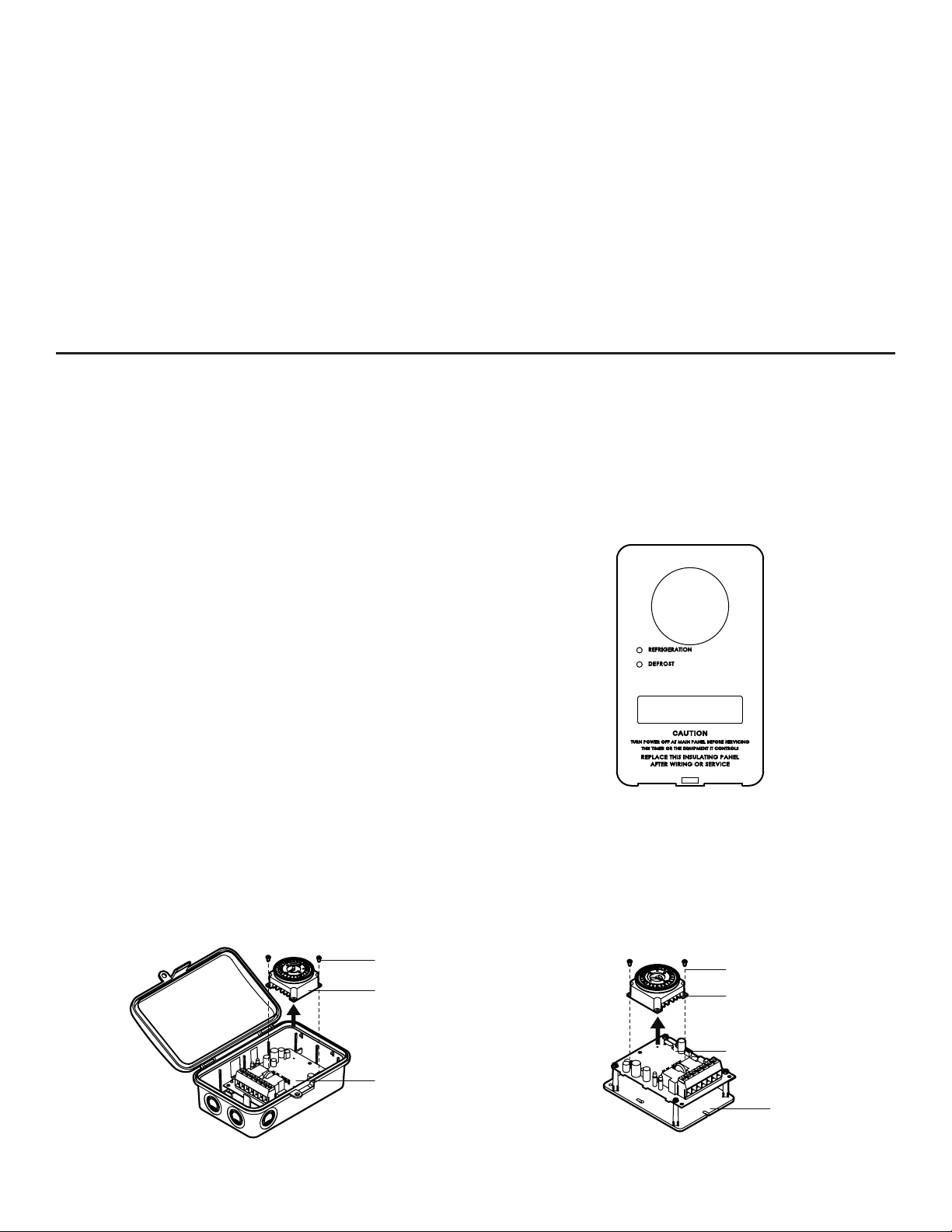
5. If applicable, remove and discard the existing dead front
cover. See FIG. 2.
Thermistor Probe Ratings:
• Thermistor*: Type NTC
• Rating:10 K Ω @ 25° C
• Wire size: 24 AWG
• Working range: -40° F to 152° F (-40° C to 67° C)
• Thermistor probe wire length: 10 ft (3.05 m)
• Connector wire length: 6 ft (1.83 m)
*Thermistor probe connections are not an isolated Class 2
circuit.
*Only use a thermistor probe specified for use with DDFM
model.
• Wire stripper
• Fish tape (possibly needed)
• Insulation tape, hose clamp, or wire ties (possibly
needed)
FIG. 2 Existing Dead Front
Install the ICUBE™ Module
1. Remove the FM timer from the control board. SeeFIG. 3 or FIG. 4.
Note: The control board does not need to be removed from the enclosure or the bracket.
FM Timer
Control Board
FIG. 3 Remove the FM Timer (Enclosed Model Shown) FIG. 4 Remove the FM Timer
ICUBE™ Adaptive Defrost Module
2
(Salable item DT-B. See DT-B Installation Instructions.)
Screw
FM Timer
Control Board
Bracket
Page 3
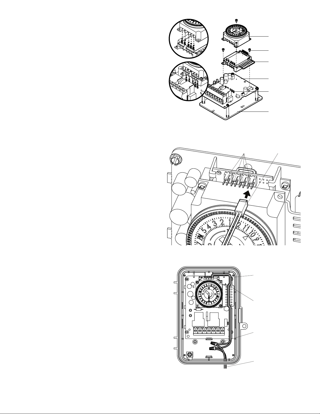
2. Orient the ICUBE™ module as shown in FIG. 5.
Input Lead
3. Install and fasten the ICUBE™ module to the control
board with the screws provided. Be sure to align the
ICUBE™ module terminals with the terminal fasteners
on the control board when placing. SeeFIG. 5.
Note: Gently tighten screws. Do not over-tighten or
stripping may occur.
4. Install and fasten the FM timer onto the ICUBE™
module with the screws provided. Be sure to align the
FM timer terminals with the terminal fasteners on the
ICUBE™ module. SeeFIG. 5 inset.
Install the Thermistor Probe
1. Route the length of field-supplied copper wire needed
to connect the thermistor probe from the evaporator
coil to the input lead. (This wire may be 18–14 AWG
shielded or unshielded up to 400 ft (121.92m) long)
FM Timer
Screw
ICUBE™
Module
Control Board
Terminal
Fasteners
Bracket
FIG. 5 Install the ICUBE™ Module (Bracket Shown)
Input Lead Connectors
Note: The field-supplied wires may run along with the
power wires through existing or new conduit.
2. Connect the input lead to the ICUBE™ module as
shown in FIG. 6. The input lead may be inserted into
any of the four connectors on the ICUBE™ module.
Note: Make sure the input pins are properly aligned with
the input lead connector.
3. Route the input lead above the tab and around the
ICUBE™ module as shown in FIG. 7.
4. Cut the input lead to the appropriate length:
– For enclosure installations, cut the input lead length
to ensure the connection is inside the enclosure as
shown in FIG. 7.
– For bracket installations, cut the input lead to an
appropriate length inside the condensing unit control
panel.
5. Use the provided wire connectors to connect the input
lead to the routed 18–14 AWG shielded or unshielded
field-supplied wire.
FIG. 6 Attach the Input Lead
Input Lead
Route Lead over Tab
Wire Connector
ICUBE™ Adaptive Defrost Module
Field-Supplied Wire
to Thermistor Probe
FIG. 7 Route the Input Lead
3
Page 4
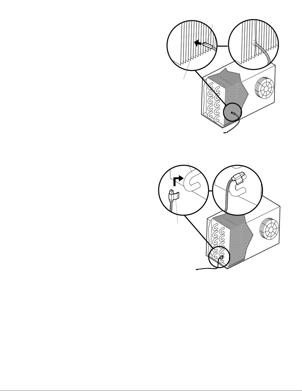
6. Connect the thermistor probe to the evaporator coil.
There are two options for probe placement.
Note: Ensure the copper tube surface area designated
for thermistor probe placement is clean. Use Emery
cloth or Evaporator cleaner to clear the surface. A
dirty surface could create an insulation barrier which
may cause inaccurate temperature readings.
– Insert the probe between the cooling fins, as shown
in FIG. 8. Ensure that the probe makes good contact
with one of the evaporator tubes. Then, using needle
nose pliers, carefully bend the cooling fins together
to hold the probe firmly in place.
– Use the provided clip, or if the clip is the incorrect
size, use another means to fasten the thermistor
probe to one of the circuit tubes e.g., hose clamp,
insulation tape, zip tie, as shown in FIG. 9. Clip the
probe onto one of the lower coils in either the
10 o'clock or 2 o'clock position, making sure that
the probe makes good contact with the evaporator
tube.
Probe
Cooling Fins
FIG. 8 Insert Thermistor Probe between Evaporator Cooling Fins
Recommended Thermistor Probe Position
The probe should be positioned and fastened wherever
frost accumulates most quickly. This is generally 1" to 2"
(2.5 cm to 5 cm) from either end, at the bottom quarter
and at the discharge side of the evaporator coil. If there
is uncertainty about where frost typically accumulates
the fastest, put the system into a manual defrost (see
"Optional: Manual Defrost" on page 6) and monitor
the last area of the evaporator where frost is present
prior to a completely frost-free coil.
Make sure the probe is not fastened in close proximity
to the electric defrost heating element.
7. Route the thermistor probe wires away from the
evaporator fans and cooling fins, avoiding pinches
and strain. Route the wire through existing or new line
voltage conduits. Secure the wires as appropriate for
your installation.
8. Use the provided wire connectors to connect the
thermistor probe wire to the routed 18–14 AWG fieldsupplied wire.
9. Use electrical tape to protect all connections against
moisture.
Evaporator Coil
Clip
FIG. 9 Connect Thermistor Probe to Evaporator Coil
10. If additional thermistor probes are needed repeat all
steps in this section. For large evaporators, additional
thermistor probes may be added to a coil on each
(opposite) side.
11. For multiple-evaporator installations, see "Optional:
Multiple Evaporators" on page 6.
ICUBE™ Adaptive Defrost Module
4
Page 5
System Startup
1. As needed, update your scheduled initiation and
termination times. See DDT40 or DTAV40 instructions
or www.intermatic.com for programming instructions.
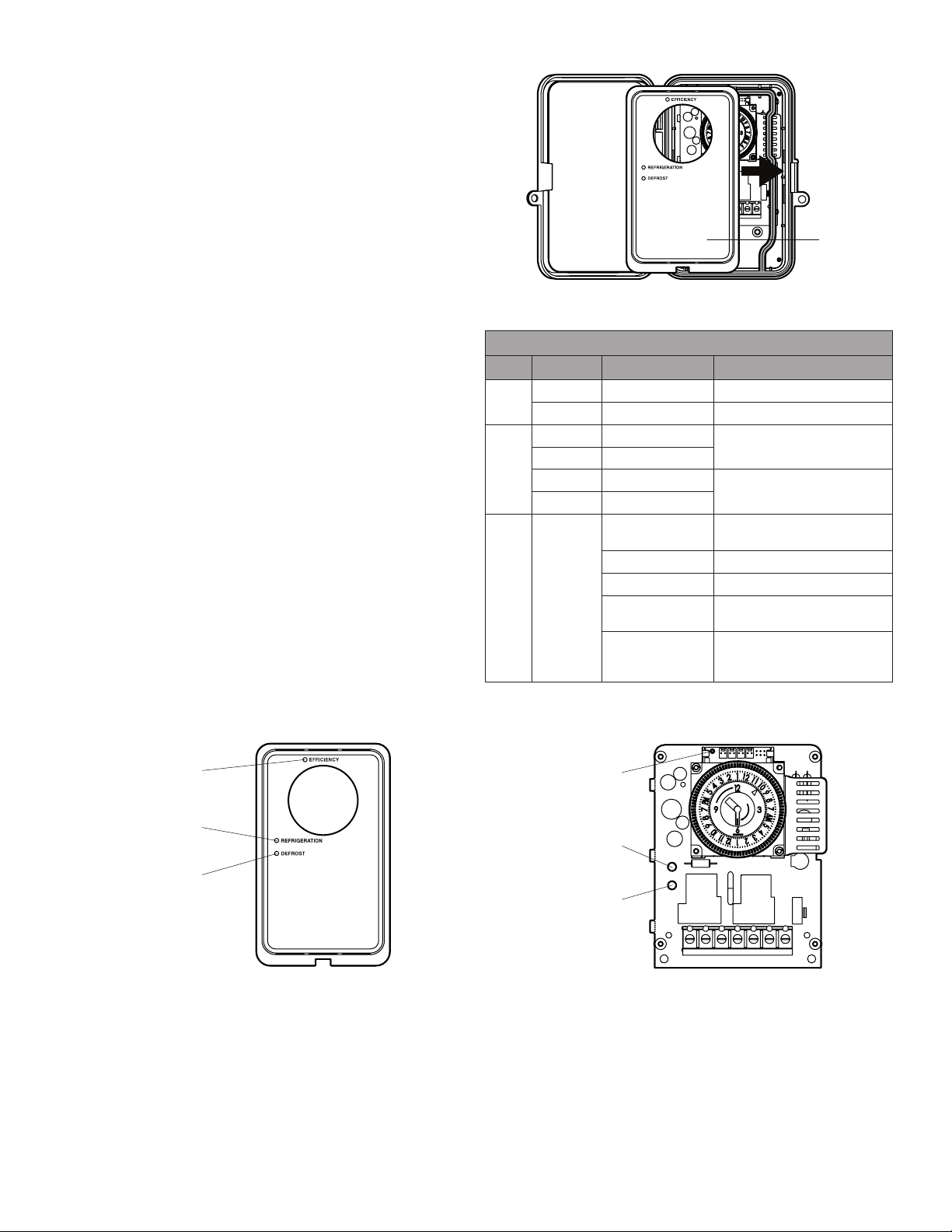
2. Snap the provided dead front cover into place, if
applicable. See FIG. 10.
3. Re-apply power to the unit.
4. The control will sense the number of probes connected.
Note: Observe the blue LED during startup in order to
verify that the ICUBE™ module registers the correct
number of thermistor probes. The blue LED will flash
once for each recognized probe.
5. See TABLE 1 and FIG. 11 or FIG. 12 to verify proper
operation of the ICUBE™ module.
Provided
Dead Front
FIG. 10 Attach the Provided Dead Front
Diagnostics
Mode LED Status Control Mode
Green LED ON Refrigeration mode active
A
Red LED OFF Defrost mode active
Green LED OFF
Red LED OFF
B
Green LED ON
Red LED ON
A/B Blue LED
ON Next scheduled defrost to be
OFF Next scheduled defrost active
1 flash/1 second Calibration mode
5 flashes/
10 seconds
1-4 flashes/
10 seconds
TABLE 1 LED Status Indicator Table
Refrigeration mode active
Defrost mode active
delayed (efficiency mode)
Thermistor sensor error
Only occurs at startup to
indicate the number of sensors
connected to the control
Blue LED
Green LED
Red LED
FIG. 11 LEDs (Enclosed Model Shown)
ICUBE™ Adaptive Defrost Module
Blue LED
Green LED
Red LED
FIG. 12 LEDs
5
Page 6
ICUBE™ FUNCTIONALITY
Modes
• Efciency Mode – Scheduled defrosts are bypassed when the control is in this state. This is indicated when the blue
LED is ON continuously. If there is no thermistor probe attached or a probe failure occurs, the ICUBE™ module operates
solely off of the defrost timer and does not enter efficiency mode.
• Calibration Mode – The ICUBE™ module enters calibration mode after the first Scheduled Defrost and after each
allowed defrost cycle. During calibration the control establishes a baseline coil behavior.
• Thermistor Probe Initialization – The number of thermistor probes connected to the control is detected during the
initial startup of the system. The blue LED flashes the number of times equal to the number of probes detected. If the
correct number of probes is not detected, disconnect power to the control before you attempt to correct the problem.
Optional: Manual Defrost
To initiate a manual defrost, rotate the FM timer dial clockwise through two consecutive scheduled defrosts within 60
seconds.
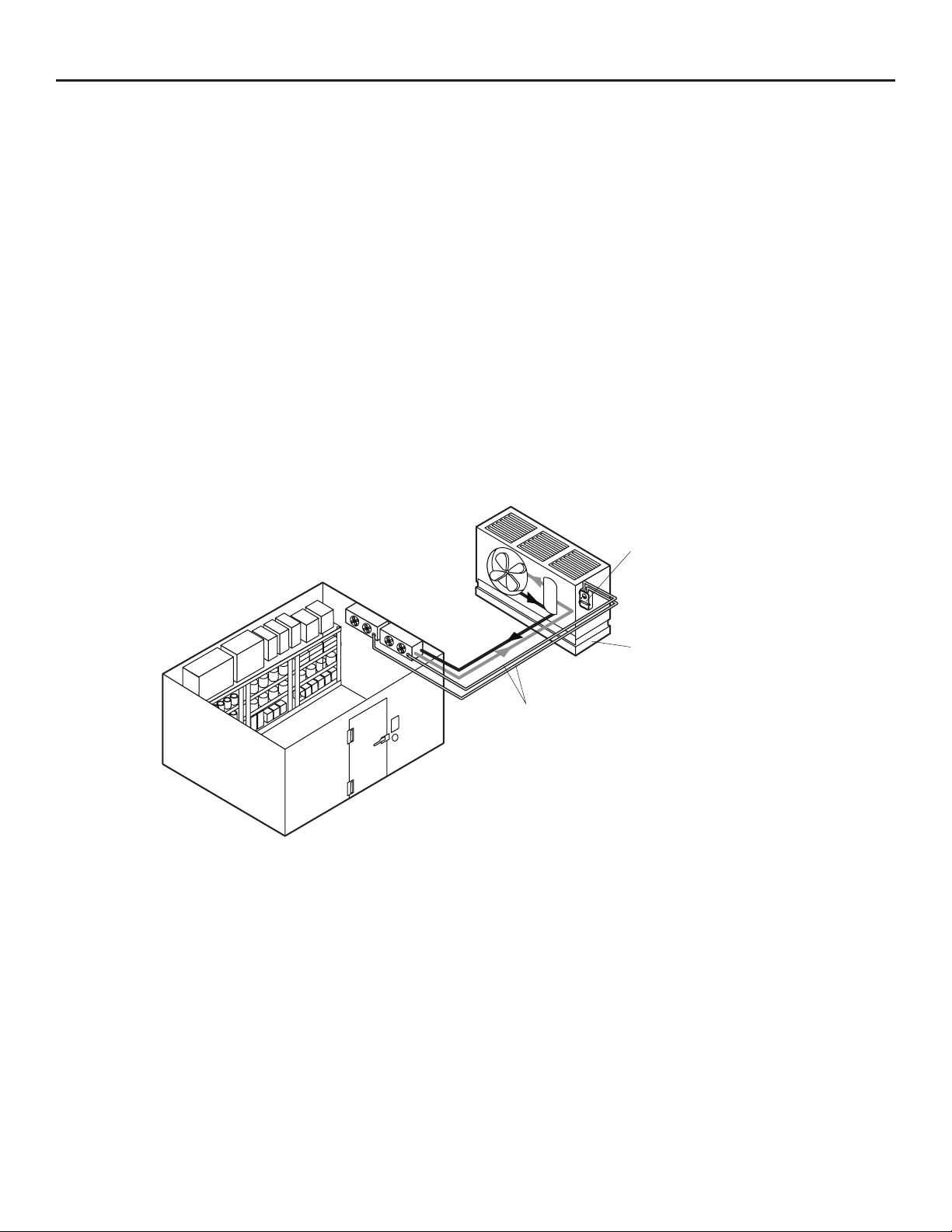
Optional: Multiple Evaporators
The ICUBE™ module has four sensor inputs that can monitor up to four evaporator coils. Typically, in a four-evaporator
system, the timer activates a contactor that energizes the multiple defrost loads simultaneously. When the ICUBE™ module
senses a decrease in capacity in one or more coils, efficiency mode shuts off and the defrost timer initiates a defrost at the
next scheduled interval as shown in FIG. 13.
Sensor Wires
FIG. 13 Evaporator System
For additional assistance, contact Technical Services at 1.815.675.7000.
ICUBE™ Module with
Grässlin™ Defrost Timer
Remote Condensing Unit
(Indoor or Outdoor)
ICUBE™ Adaptive Defrost Module
6
©2016 Intermatic
Page 7

SpringGrove, Illinois60081, États-Unis
www.intermatic.com
Module de dégivrage adaptatif ICUBEMC
Manuel d’installation et d’utilisation
SECTION RELATIVE À LA SÉCURITÉ
AVERTISSEMENT
Risque d’incendie et d’électrocution
• Couper l’alimentation aux disjoncteurs ou aux sectionneurs avant toute installation ou toute intervention.
• Plusieurs disjoncteurs ou sectionneurs peuvent être nécessaires pour mettre
l’équipement hors tension avant l’intervention.
• L’installation et le câblage doivent être réalisés conformément aux exigences des
normes électriques nationales et régionales.
• Consulter le modèleDTAV40 ouDDT40 pour des avertissements et des instructions d’installation supplémentaires. Rendez-vous sur www.intermatic.com si
nécessaire.
• Utiliser uniquement la trousse de sonde à thermistance fournie par Intermatic.
Les raccordements vers les panneaux de commandeDTAV40 etDDT40 ne sont
PAS des circuits isolés de catégorie2. Utiliser des conducteurs en cuivre de18 à
14AWG pour le câble installé sur place à la sonde à thermistance.
• Tourner le bouton de la minuterie dans le sens horaire uniquement pour éviter
d’endommager la minuterie.
• Ne pas déplacer les aiguilles de la minuterie. Un déplacement manuel des
aiguilles risque d’endommager la minuterie.
• Il est possible de rallonger le câble de thermistance jusqu’à 122m (400pi) à
l’aide du câblage installé sur place entre le panneau de commandeDDT40 et
l’emplacement de la sonde à thermistance.
• Ce produit est adapté uniquement aux modèlesDTAV40 et DDT40 de GrässlinMC.
Toutes les marques de commerce appartiennent à leurs
propriétaires respectifs.
AVIS
DESCRIPTION DU PRODUIT
Le module de dégivrage adaptatif ICUBEMC installé avec un panneau de commande de dégivrage DTAV40 existant de
GrässlinMC permet au panneau de commandeDTAV40 de passer outre des événements de dégivrage programmés lorsqu’ils
sont inutiles, pour économiser de l’énergie. Il est possible d’ajouter jusqu’à quatre sondes à thermistance au panneau de
commande pour surveiller plusieurs serpentins d’évaporateur. Il est possible d’installer les sondes à thermistance jusqu’à
122m(400pi) du module ICUBEMC sur un groupe compresseur-condenseur dédié ou multiplex à distance (à l’intérieur ou à
l’extérieur), ou dans le boîtier congélateur/refroidisseur. Il n’est pas nécessaire de modifier le câblage des bornes du panneau
de commande de dégivrage installé (par exemple, le câblage des ventilateurs, du dispositif de chauffage de dégivrage ou du
thermostat).
Pour commander d’autres trousses de sonde à thermistance (par exemple, pour raccorder plusieurs évaporateurs à un
panneau de commande), utiliser la référence178GR10K-1.
Contenu du module de dégivrage adaptatif ICUBEMC – RéférenceDDFM
La trousse comprend:
• Une sonde à thermistance de 3,05m (10pi), avec
attache
• Un câble d’entrée de 1,83m (6pi)
• Quatre connecteurs de câble
• Un écran isolant
• Un module de dégivrage adaptatif ICUBEMC, DDFM
• Quatre vis nº4-40 de 6,35mm (¼po)
FIG. 1 Contenu de la trousse du module ICUBE
MC
Page 8

Caractéristiques
Vis
Entrée nominale:
120/240Vc.a., 50mA, 60Hz
Valeurs nominales relatives à la sonde à
thermistance:
• Thermistance*: TypeNTC
• Valeur nominale: 10KΩ à 25°C
• Dimension du câble: AWG nº24
• Plage de fonctionnement: -40°C à 67°C
(-40°F à 152°F)
• Longueur du câble de la sonde à thermistance: 3,05m
(10pi)
• Longueur de câble de connecteur: 1,83m (6pi)
*Les connexions de la sonde à thermistance ne sont pas des
circuits isolés de catégorie2.
*Utiliser uniquement une sonde à thermistance conçue pour
être utilisée avec le modèleDDFM.
INSTALLATION
Remarque: Consulter la section AVERTISSEMENTS, page 7, avant de continuer.
Outils requis
• Un petit tournevis plat ou de type TORXMC nº4-40
• Une pince à bec effilé
• De la toile émeri ou un nettoyant pour évaporateur
• Une pince coupante
Avant l’installation
1. Couper l’alimentation vers le panneau de commande
au niveau du disjoncteur ou du sectionneur. Plusieurs
disjoncteurs ou sectionneurs peuvent être nécessaires
pour mettre le panneau de commande et toutes les
charges connectées hors tension.
2. Évaluer la longueur de câble en cuivre installé sur place
nécessaire pour raccorder la sonde à thermistance
depuis le serpentin d’évaporateur vers le câble
d’entrée. (Ce câble peut être blindé ou non, de
calibre 18 à 14AWG, et d’une longueur allant jusqu’à
121,92m[400pi]).
3. Il est possible d’installer le panneau de commande
existant dans un boîtier (comme illustré à laFIG. 3,
par exemple) ou de la fixer sur un support à l’intérieur
du panneau de commande du groupe compresseurcondenseur (comme illustré à laFIG. 4, par exemple).
L’installation du module ICUBEMC est le même pour les
deux exemples.
4. Ouvrir la porte du boîtier, le cas échéant.
5. Retirer et mettre de côté le couvercle de l’écran isolant
existant, le cas échéant. VoirFIG. 2.
Installation du module ICUBE
1. Retirer la minuterieFM du panneau de commande. VoirFIG. 3 ou FIG. 4.
Remarque: Il n’est pas nécessaire de retirer le panneau de commande du boîtier ou du support.
MC
• Une pince à dénuder
• Du câble de traction (éventuellement nécessaire)
• Du ruban isolant, un collier de serrage ou des serrecâbles (éventuellement nécessaires)
FIG. 2 Écran isolant existant
FIG. 3 Retrait de la minuterieFM (modèle avec boîtier) FIG. 4 Retrait de la minuterieFM
Module de dégivrage adaptatif ICUBE
Vis
Minuterie FM
Panneau de
commande
MC
8
(ArticleDT-B en vente. Voir les instructions d’installation du DT-B.)
Minuterie FM
Panneau de
commande
Support
Page 9

2. Orienter le module ICUBEMC comme indiqué à la FIG. 5.
Connecteurs du
3. Installer et fixer le module ICUBEMC au panneau de
commande avec les vis fournies. Veiller à aligner les
bornes des modules ICUBEMC avec les attaches
des bornes sur le panneau de commande lors de
l’installation. VoirFIG. 5.
Remarque: Serrer doucement les vis. Ne pas trop serrer,
car cela pourrait provoquer un décapage.
4. Installer et fixer la minuterieFM au module ICUBEMC
avec les vis fournies. Veiller à aligner les bornes de
la minuterieFM avec les attaches des bornes sur le
module ICUBEMC. Voir l’encart de laFIG. 5.
Installation de la sonde à thermistance
1. Acheminer la longueur de câble en cuivre installé
sur place nécessaire pour raccorder la sonde à
thermistance depuis le serpentin d’évaporateur vers le
câble d’entrée. (Ce câble peut être blindé ou non, de
calibre 18 à 14AWG, et d’une longueur allant jusqu’à
121,92m[400pi]).
Minuterie FM
Vis
Module
MC
ICUBE
Panneau de
commande
Attaches des
bornes
Support
FIG. 5 Installation du module ICUBEMC (modèle avec support)
câble d’entrée
Câble d’entrée
Remarque: Les câbles installés sur place peuvent longer
les câbles d’alimentation dans un conduit
existant ou un nouveau conduit.
2. Raccorder le câble d’entrée au module ICUBEMC,
comme illustré à laFIG. 6. Il est possible d’insérer le
câble d’entrée dans l’un des quatre connecteurs du
module ICUBEMC.
Remarque: Veiller à ce que les broches d’entrée soient
bien alignées avec le connecteur du câble
d’entrée.
3. Acheminer le câble d’entrée au-dessus de la languette
et autour du module ICUBEMC, comme illustré à
laFIG. 7.
4. Couper le câble d’entrée à la longueur appropriée:
– Pour les installations avec boîtier, couper le câble
d’entrée de manière à adapter le raccordement à
l’intérieur du boîtier, comme illustré à laFIG. 7.
– Pour les installations avec support, couper le câble
d’entrée à une longueur appropriée à l’intérieur du
panneau de commande du groupe compresseurcondenseur.
5. Utiliser les connecteurs de câbles fournis pour
raccorder le câble d’entrée au câble, blindé ou non, de
18 à 14AWG acheminé, installé sur place.
FIG. 6 Branchement du câble d’entrée
Câble d’entrée
Acheminer le câble
par-dessus la languette
Connecteur de câble
Câble installé sur
place vers la sonde
à thermistance
Module de dégivrage adaptatif ICUBE
FIG. 7 Acheminement du câble d’entrée
MC
9
Page 10

6. Raccorder la sonde à thermistance au serpentin
d’évaporateur. La sonde peut être positionnée de deux
manières.
Remarque: S’assurer que la surface du tube de cuivre
désignée pour le positionnement de la sonde
à thermistance est propre. Utiliser la toile
émeri ou le nettoyant pour évaporateur pour
nettoyer la surface. Une surface sale peut
créer une barrière d’isolation du périmètre
susceptible d’entraîner des lectures inexactes
de la température.
– Insérer la sonde entre les ailettes de
refroidissement, comme illustré à laFIG. 8.
S’assurer du bon contact entre la sonde
et l’un des tubes de l’évaporateur. Ensuite,
en utilisant une pince à bec effilé, pincer
soigneusement les ailettes de refroidissement
pour maintenir fermement la sonde en place.
– Utiliser la pince fournie ou un autre moyen (par
ex. un collier, du ruban isolant ou une attache
autobloquante), si la taille de la pince n’est pas
adaptée, pour fixer la sonde à thermistance à
l’un des tubes du circuit, comme illustré à la
FIG. 9. Attacher la sonde à l’un des serpentins
inférieurs, en position 10h ou 2h, en
s’assurant qu’elle est bien en contacte avec le
tube de l’évaporateur.
Sonde
Ailettes de
refroidissement
FIG. 8 Insertion de la sonde à thermistance entre les ailettes de
refroidissement de l’évaporateur
Serpentin d’évaporateur
Position conseillée de la sonde à thermistance
La sonde doit être positionnée et fixée à un endroit
où le givre s’accumule le plus rapidement. Cet
emplacement se trouve généralement entre 2,5cm et
5cm (entre 1po et 2po) des extrémités, au niveau du
quart inférieur et du côté refoulement du serpentin de
l’évaporateur. En cas de doute sur l’emplacement où
le givre s’accumule généralement le plus rapidement,
mettre le système en mode de dégivrage manuel
(voir«En option: dégivrage manuel», page12) et
surveiller la dernière zone de l’évaporateur où le givre
est présent avant de disparaître complètement du
serpentin.
S’assurer que la sonde n’est pas fixée à proximité de
l’élément de chauffage du système de dégivrage.
7. Acheminer la sonde à thermistance loin des ventilateurs
de l’évaporateur et des ailettes de refroidissement, en
évitant les pincements et les tensions. Acheminer le
câble dans des conduits de tension de ligne existants
ou dans de nouveaux conduits. Fixer les câbles en
fonction de votre installation.
8. Utiliser les connecteurs de câbles fournis pour
raccorder la sonde à thermistance au câble de 18 à
14AWG acheminé, installé sur place.
9. Utiliser du ruban isolant pour protéger tous les
raccordements contre l’humidité.
10. Si des sondes à thermistance supplémentaires
s’avèrent nécessaires, répéter toutes les étapes de
cette section. Pour les grands évaporateurs, il est
possible d’ajouter des sondes à thermistance sur un
serpentin de chaque côté (opposé).
11. Pour les installations à plusieurs évaporateurs, voir «En
option: plusieurs évaporateurs», page12.
Attache
FIG. 9 Raccordement de la sonde à thermistance au serpentin de
l’évaporateur
Module de dégivrage adaptatif ICUBE
MC
10
Page 11

Démarrage du système
1. Au besoin, mettre à jour les heures de lancement
et d’arrêt programmés. Voir les instructions pour
le modèleDDT40 ouDTAV40, ou rendez-vous sur
www.intermatic.com pour obtenir les instructions de
programmation.
2. Remettre en place le couvercle de l’écran isolant fourni,
le cas échéant. VoirFIG. 10.
3. Rebrancher l’alimentation de l’unité.
4. Le panneau de commande détecte le nombre de
sondes connectées. Remarque: Observer la DEL
bleue lors du démarrage afin de vérifier que le module
ICUBEMC enregistre le bon nombre de sondes à
thermistance. La DEL bleue clignote une fois pour
chaque sonde reconnue.
5. Voir TABLEAU1 et FIG. 11 ou FIG. 12 pour vérifier le
bon fonctionnement du module ICUBEMC.
Écran isolant
fourni
FIG. 10 Mise en place de l’écran isolant fourni
Diagnostics
Mode DEL État Mode du panneau de
commande
DEL verte ALLUMÉE Mode réfrigération actif
A
DEL rouge ÉTEINTE Mode dégivrage actif
DEL verte ÉTEINTE
DEL rouge ÉTEINTE
B
DEL verte ALLUMÉE
DEL rouge ALLUMÉE
A/B DEL bleue
TABLEAU1 Tableau d’indication d’état des DEL
ALLUMÉE Prochain dégivrage programmé à
ÉTEINTE Prochain dégivrage programmé actif
1clignotement/
1seconde
5clignotements/
10secondes
1 à 4clignotements/
10secondes
Mode réfrigération actif
Mode dégivrage actif
retarder (mode économique)
Mode d’étalonnage
Erreur au niveau du capteur à
thermistance
Se produit uniquement au
démarrage pour indiquer le nombre
de capteurs connectés au panneau
de commande
DEL bleue
DEL verte
DEL rouge
FIG. 11 DEL (modèle avec boîtier)
Module de dégivrage adaptatif ICUBE
DEL bleue
DEL verte
DEL rouge
FIG. 12 DEL
MC
11
Page 12

FONCTIONNALITÉ ICUBE
MC
Modes
• Mode économique: les dégivrages programmés sont ignorés lorsque ce mode est activé pour le panneau de
commande. Cela correspond à la DEL bleue allumée en permanence. Si aucune sonde à thermistance n’a été fixée
ou en cas de panne de la sonde, le module ICUBEMCfonctionne uniquement à partir de la minuterie de dégivrage et ne
passe pas en mode économique.
• Mode d’étalonnage – le module ICUBEMC passe en mode d’étalonnage après le premier dégivrage programmé et
après chaque cycle de dégivrage autorisé. Lors de l’étalonnage, le panneau de commande établit un comportement de
base du serpentin.
• Initialisation de la sonde à thermistance: le nombre de sondes à thermistance connectées au panneau de
commande est détecté uniquement lors du démarrage initial du système. La DEL bleue émet un nombre de
clignotements correspondant au nombre de sondes détectées. Si le bon nombre de sondes n’est pas détecté,
débrancher l’alimentation du panneau de commande avant d’essayer de résoudre le problème.
En option: dégivrage manuel
Pour lancer un dégivrage manuel, tourner le bouton de la minuterieFM dans le sens horaire pour passer deux dégivrages
programmés consécutifs en 60secondes.
En option: plusieurs évaporateurs
Le module ICUBEMC présente quatre entrées de capteur qui permettent de contrôler jusqu’à quatre serpentins d’évaporateur.
Généralement, dans un système comprenant quatre évaporateurs, la minuterie active un contacteur qui alimente les multiples
charges de dégivrage en même temps. Lorsque le module ICUBEMC détecte une diminution de la capacité d’un ou de
plusieurs serpentins, le mode économique se désactive et la minuterie de dégivrage lance un dégivrage au prochain intervalle
programmé, comme illustré à la FIG. 13.
MC
Module ICUBE
de dégivrage Grässlin
Groupe compresseur-condenseur à distance
(à l’intérieur ou à l’extérieur)
Câbles des capteurs
FIG. 13 Système d’évaporateur
équipé d’une minuterie
MC
Pour toute assistance complémentaire, communiquer avec le service technique au 1-815-675-7000.
Module de dégivrage adaptatif ICUBE
MC
12
©2016 Intermatic
Page 13

Spring Grove, Illinois 60081
www.intermatic.com
Módulo adaptable de descongelación
ICUBE™
Manual de instalación y operación
SECCIÓN DE SEGURIDAD
ADVERTENCIA
Riesgo de incendio o descarga eléctrica
• Desconecte el suministro eléctrico de los disyuntores o los interruptores de
desconexión antes de comenzar la instalación o el mantenimiento.
• Es posible que se requiera más de un disyuntor o interruptor de desconexión
para desenergizar el equipo antes del mantenimiento.
• La instalación y el cableado deben realizarse de conformidad con las disposiciones de los códigos eléctricos locales y nacionales.
• Consulte DTAV40 o DDT40 para conocer otras advertencias e instrucciones de
instalación. Visite www.intermatic.com en caso necesario.
• Solo use el kit de sondas para termistor de Intermatic que se incluye. Las
conexiones de sondas a los controles DTAV40 y DDT40 NO corresponden a un
circuito aislado Clase 2. Use conductores de cobre AWG 18-14 para los cables
proporcionados en el lugar de instalación para la sonda de termistor.
• Solo debe girar el disco selector del temporizador en el sentido de las manecillas
del reloj, si lo gira en el sentido contrario dañará el temporizador.
• No mueva las manecillas del reloj del temporizador. Si las mueve de forma
manual se dañará el temporizador.
• El cable del termistor puede extenderse hasta 122m (400 pies) si usa el
cableado provisto en terreno entre la ubicación del control DDT40 y la sonda del
termistor.
• Este producto está destinado para uso exclusivo con los modelos DTAV40 y
DDT40 de Grässlin™.
AVISO
Todas las marcas registradas son de propiedad de sus respectivos dueños.
DESCRIPCIÓN DEL PRODUCTO
Cuando se agrega el Módulo adaptable de descongelación ICUBE™ a un control de descongelación existente DTAV40
de Grässlin™, proporciona al control DTAV40 la capacidad de omitir eventos de descongelación programados cuando
no se necesitan con el fin de ahorrar energía. Se pueden agregar hasta cuatro sondas de termistor al control con el fin
de monitorear varios serpentines de evaporador. Las sondas de termistor se pueden instalar hasta 122m(400pies) del
módulo ICUBE™ en una unidad de condensación remota dedicada o múltiple (para interior o exterior) o dentro de la caja del
congelador/refrigerador. No es necesario realizar cambios al cableado del terminal de control de descongelación instalado
(como el cableado para los ventiladores, calefactor de descongelación o termostato).
Para pedir kits de sondas de termistor adicionales (por ejemplo, para conectar varios evaporadores a un control), use el
número de pieza 178GR10K-1.
Contenidos del Módulo adaptable de descongelación ICUBE™ – Número de pieza DDFM
El kit incluye:
• Una sonda de termistor de 3,05m(10pies) con abrazadera
• Un cable de entrada de 1,83m (6pies)
• Cuatro conectores de cable
• Un frente muerto
• Un módulo adaptable de descongelación ICUBE™,
DDFM
• Cuatro tornillos de ¼" nº 4-40
FIG. 1 Contenidos del kit del módulo ICUBE™
Page 14

Especicaciones
Tornillo
Capacidad de entrada:
120/240 VCA, 50mA, 60Hz
Capacidades de las sondas del termistor:
• Termistor*: tipo NTC
• Capacidad:10 K Ω @ 25 °C
• Tamaño del cable: calibre 24 (AWG)
• Rango de funcionamiento: -40°C a 67°C (-40°F a 152°F)
• Longitud de cable de sonda de termistor: 3,05m (10 pies)
• Longitud de cable de conector: 1,83 m (6 pies)
*Las conexiones de la sonda del termistor no corresponden
a un circuito aislado Clase 2.
*Solo use sondas de termistor especificadas para el modelo
DDFM.
INSTALACIÓN
Nota: Consulte las ADVERTENCIAS en la página 13 antes de proceder.
Herramientas necesarias
• Destornillador plano pequeño o TORX™ nº4-40
• Alicates de punta fina
• Paño de lija o limpiador evaporador
• Cortacables
Previo a la instalación
1. Desconecte la alimentación que va al control desde
el disyuntor o interruptor de desconexión. Es posible
que se requiera más de un disyuntor o interruptor para
desenergizar el control y todas las cargas conectadas.
2. Planifique el largo del cable de cobre proporcionado en el
lugar de instalación necesario para conectar la sonda del
termistor desde el serpentín del evaporador al conductor
de entrada. (Este cable puede ser AWG 18-14 blindado
o no y hasta de 121,92 m (400 pies) de largo).
3. El control existente se puede instalar en una caja (como
se muestra en la FIG. 3, por ejemplo) o se puede fijar
en un soporte adentro del panel de control de la unidad
de condensación (como se muestra en la FIG. 4, por
ejemplo). La instalación del módulo ICUBE™ es la
misma en ambos casos.
4. Si corresponde, abra la puerta de la caja.
5. Si corresponde, extraiga y deseche la cubierta del frente
muerto actual. Consulte FIG. 2.
• Pelacables
• Alambre guía (posiblemente necesario)
• Cinta aisladora, abrazadera de manguera o bridas para
cables (posiblemente necesarias)
FIG. 2 Frente muerto actual
Instalar el módulo ICUBE™
1. Extraiga el temporizador FM del panel de control. ConsulteFIG. 3 o FIG. 4.
Nota: No es necesario extraer el panel de control de la caja o el soporte.
Tornillo
Temporizador FM
FIG. 3 Extraer el temporizador FM (se muestra modelo adjunto) FIG. 4 Extraer el temporizador FM (Artículo vendible DT-B.
ICUBE™ Adaptive Defrost Module
Panel de control
Consulte las instrucciones de instalación de DT-B).
14
Temporizador FM
Panel de control
Soporte
Page 15

2. Oriente el módulo ICUBE™ como se muestra en la FIG.
emporizador FM
Conectores del cable
5.
3. Instale y asegure el módulo ICUBE™ al panel de
control con los tornillos incluidos. Cuando lo instale,
debe alinear los terminales del módulo ICUBE™
con los fiadores de terminales del panel de control.
ConsulteFIG. 5.
Nota: Apriete los tornillos con suavidad. No apriete en
exceso o puede haber desprendimiento.
4. Instale y asegure el temporizador FM en el módulo
ICUBE™ con los tornillos incluidos. Debe alinear los
terminales del temporizador FM con los fiadores de los
terminales en el módulo ICUBE™. ConsulteFIG. 5 en el
recuadro.
Instalar la sonda del termistor
1. Guíe el largo del cable de cobre proporcionado en el
lugar de instalación necesario para conectar la sonda
del termistor desde el serpentín del evaporador al
conductor de entrada. (Este cable puede ser AWG
18–14 blindado o no y hasta de 121,92m (400 pies) de
largo).
Nota: Los cables proporcionados en el lugar de
instalación pueden ir junto a los cables de
alimentación a través de conductos nuevos o
existentes.
2. Conecte el cable de entrada al módulo ICUBE™ como
se muestra en la FIG. 6. El cable de entrada se puede
conectar en cualquiera de los cuatros conectores del
módulo ICUBE™.
Nota: Asegúrese de que las clavijas de entrada estén bien
alineadas con el cable del conector de entrada.
T
Tornillo
Módulo
ICUBE™
Panel de control
Fiadores de
terminales
Soporte
FIG. 5 Instalar el módulo ICUBE™ (se muestra en soporte)
de entrada
FIG. 6 Conectar el cable de entrada
Cable de entrada
3. Guíe el cable de entrada sobre la lengüeta y alrededor
del módulo ICUBE™ tal como se muestra en la FIG. 7.
4. Corte el cable de entrada al largo apropiado:
– Para la instalación de la caja, corte el largo del cable
de entrada para asegurarse de que la conexión esté
dentro de la caja tal como se muestra en la FIG. 7.
– Para instalaciones en soporte, corte el cable de
entrada al largo correspondiente para que quede
dentro de la unidad de condensación del panel de
control.
5. Use los conectores de cable incluidos para conectar el
cable de entrada al cable proporcionado y guiado con o
sin blindaje AWG 18–14.
ICUBE™ Adaptive Defrost Module
Cable de entrada
Guiar cable sobre
la lengüeta
Conector de cable
Cable proporcionado
en el lugar a sonda
de termistor
FIG. 7 Guiar el cable de entrada
15
Page 16

6. Conecte la sonda del termistor al serpentín del
evaporador. Hay dos opciones para colocar la sonda.
Nota: Verifique que esté limpia el área de la superficie del
tubo de cobre destinada para colocar la sonda del
termistor. Use paño de lija o limpiador evaporador
para limpiar la superficie. Si la superficie está
sucia podría crear una barrera aislante que puede
provocar lecturas inexactas de la temperatura.
– Inserte la sonda entre las aletas de refrigeración,
tal como se muestra en FIG. 8. Verifique que la
sonda haga buen contacto con uno de los tubos del
evaporador. Luego, con los alicates de punta fina,
doble cuidadosamente las aletas de refrigeración
para que queden juntas y sostengan firmemente la
sonda en su lugar.
– Use la abrazadera incluida pero si su tamaño no
es el correcto, use otro medio para atar la sonda
del termistor a uno de los tubos del circuito, por
ejemplo, abrazadera de manguera, cinta aisladora,
abrazadera plástica, tal como se muestra en FIG.
9. Enganche la sonda en uno de los serpentines
inferiores, ya sea en la posición de las 10 en punto o
las 2 en punto, asegurándose de que la sonda haga
buen contacto con el tubo del evaporador.
Posición recomendada de la sonda del termistor
La sonda se debe colocar y atar donde se acumule
la escarcha más rápidamente. Por lo general, esto
es de 2,5cma5cm(1" a 2") de cualquiera de los
extremos, en el cuarto inferior y en el lado de descarga
del serpentín del evaporador. Si no está seguro de
dónde se acumula más rápidamente la escarcha,
ponga el sistema en descongelación manual (consulte
"Opcional: Descongelación manual" en la página
18) y monitoree cuál es la última zona donde queda
escarcha en el evaporador antes de que el serpentín
esté completamente sin hielo.
La sonda no se debe atar muy cerca del elemento
calefactor eléctrico de descongelamiento.
Sonda
Aletas de
refrigeración
FIG. 8 Insertar la sonda del termistor entre las aletas de refrigeración del
evaporador
Serpentín de evaporador
Abrazadera
7. Guíe los cables de la sonda del termistor lejos de los
ventiladores del evaporador y las aletas de refrigeración,
evitando que se pellizquen o queden tirantes. Guíe el
cable por los conductos de línea de voltaje nuevos o
existentes. Afirme los cables según corresponda para
su instalación.
8. Use los conectores de cable incluidos para conectar
el cable de la sonda del termistor al cable AWG 18–14
proporcionado en lugar de instalación que ya se ha
guiado.
9. Use cinta aislante para proteger todas las conexiones
de la humedad.
10. Si se requieren más sondas de termistor, repita todos
los pasos de esta sección. Para evaporadores de gran
tamaño, puede agregar sondas de termistor adicionales
a un serpentín a cada lado (opuesto).
11. Para instalaciones con varios evaporadores, consulte
"Opcional: Varios evaporadores" en la página 18.
ICUBE™ Adaptive Defrost Module
FIG. 9 Conectar la sonda del termistor al serpentín del evaporador
16
Page 17

Arranque del sistema
1. Según sea necesario, actualice los tiempos de inicio y
término programados. Consulte las instrucciones de
DDT40 o DTAV40 o visite www.intermatic.com para ver
las instrucciones de programación.
2. Vuelva a colocar la cubierta del frente muerto en su
lugar, si corresponde. Consulte FIG. 10.
3. Vuelva a aplicar alimentación a la unidad.
4. El control detectará la cantidad de sondas conectadas.
Nota: Observe la luz LED azul durante el arranque para
verificar que el módulo ICUBE™ registra la cantidad
correcta de sondas de termistor. La luz LED azul
destellará una vez por cada sonda reconocida
5. Consulte la "TABLA 1 Tabla de indicadores de estado
LED" en la página 17 y la FIG. 11 o FIG. 12 para
verificar el funcionamiento correcto del módulo
ICUBE™.
Frente muerto
incluido
FIG. 10 Colocar el frente muerto incluido
Diagnóstico
Modo LED Estado Modo de control
LED verde ON Modo de refrigeración activo
A
LED rojo OFF Modo de descongelación activo
LED verde OFF
LED rojo OFF
B
LED verde ON
LED rojo ON
A/B LED azul
TABLA 1 Tabla de indicadores de estado LED
ON Se retrasará la próxima
OFF Próxima descongelación
1 destello/
1 segundo
5 destellos/
10 segundos
1-4 destellos/
10 segundos
Modo de refrigeración activo
Modo de descongelación activo
descongelación programada
(modo de eficiencia)
programada activa
Modo de calibración
Error de sensor de termistor
Solo ocurre en el arranque para
indicar la cantidad de sensores
conectados al control
LED azul
LED verde
LED rojo
FIG. 11 LED (se muestra el modelo adjunto)
ICUBE™ Adaptive Defrost Module
LED azul
LED verde
LED rojo
FIG. 12 LED
17
Page 18

FUNCIONALIDAD DEL ICUBE™
Modos
• Modo de eciencia: cuando el control está en este estado, las descongelaciones programadas se derivan. Esto se
indica mediante la luz LED encendida de forma continua. Si no hay una sonda de termistor adjunta o se produce un
error de la sonda, el módulo ICUBE™ funciona únicamente fuera del temporizador de descongelación y no entra en el
modo de eficiencia.
• Modo de calibración – el módulo ICUBE™ entra en el modo de calibración después de la primera descongelación
programada y después de cada ciclo de descongelación permitido. Durante la calibración el control establece un
comportamiento inicial del serpentín.
• Inicialización de sondas de termistor: la cantidad de sondas de termistor conectadas al control se detecta
durante el arranque inicial del sistema. La luz LED azul destella la misma cantidad de veces que la cantidad de sondas
detectadas. Si no se detecta la cantidad correcta de sondas, desconecte la alimentación del control antes de intentar
corregir el problema.
Opcional: Descongelación manual
Para iniciar una descongelación manual, gire el disco selector del temporizador FM en el sentido de las manecillas del reloj
por dos descongelaciones consecutivas programadas dentro de 60 segundos.
Opcional: Varios evaporadores
El módulo ICUBE™ tiene cuatro entradas de sensor que pueden monitorear hasta cuatro serpentines de evaporador. Por
lo general, en un sistema de cuatro evaporadores, el temporizador activa un contactor que energiza simultáneamente las
diversas cargas de descongelación. Cuando el módulo ICUBE™ detecta una disminución de capacidad en uno o más
serpentines, el modo de eficiencia se desactiva y el temporizador de descongelación inicia una descongelación en el próximo
intervalo programado tal como se muestra en la FIG. 13.
Módulo ICUBE™ con temporizador
de descongelación Grässlin™
Unidad condensadora remota
(aplicaciones en interior o exterior)
Cables de sensor
FIG. 13 Sistema del evaporador
Para obtener asistencia adicional, comuníquese con el Servicio técnico al 1.815.675.7000.
ICUBE™ Adaptive Defrost Module
18
©2016 Intermatic
158--01878
 Loading...