

Page 1

Installation &
Paragon Precision
TIME INITIATED, TIME TERMINATED
Grasslin
Operating Instructions
DTAV40 Series Time Initiated, Temperature, Pressure or
Time Terminated Auto-Voltage 40A Defrost Timers
WARNING
• Disconnect power at the circuit breaker(s) or disconnect switch(es) before installing or servicing.
• More than one circuit breaker or disconnect switch may be required to de-energize the equipment before
servicing.
• Installation and/or wiring must be in accordance with national and local electrical code requirements.
• For 40 amp loads, use #8 AWG wire, rated 90° C min.
• Bonding between conduit connections is not automatic and must be provided as part of the installation.
• When replacing a timer with a metal bracket, replace the bracket with a non-metallic bracket. (Intermatic
Model DT-B is recommended).
• For outdoor locations, raintight, or wet location, conduit hubs that comply with requirements of UL514B
(standard for fittings for conduit and outlet boxes) are to be used.
NOTICE
• Rotate timer dial clockwise only.
• Do not move the clock hands on the timer. Moving the clock hands can damage the timer.
Mode Selection Switch (S1)
UL TYPE 3R ENCLOSURE
Risk of Fire or Electric Shock
Risk of Damage to Timer
UL TYPE 1 ENCLOSURE
BRACKET MOUNT
(Saleable item DT-B)
SEE SEPARATE BRACKET
REPLACEMENT NOTICE
IN PACKAGE
Set Mode Selection (See S1 DIP Switch, table and instructions below).
MODE SELECTION (S1 DIP SWITCH):
First determine what model is being replaced (Grasslin or Competitors).
The mode selector DIP switch (located at lower right side of the board)
determines the configuration of terminals 2 & 4. In position “A”, the terminals are normally closed, and will open during a defrost. In position “B”,
terminals 2 & 4 are normally open, and will close during a defrost. Select
proper position from table below and wiring diagrams indicated.
To select mode simply slide the switch as follows:
Mode A - position switch up;
Mode B - position switch down;
Note: When Mode “B” is selected the
DTAV40 will operate as follows:
Refrigeration Mode - Red & Green LEDs
will turn OFF (1 & 3 and 2 & 4 break while
1 & F make)
Defrost Mode - RED & GREEN LEDs will turn
ON (1 & 3 and 2 & 4 make while 1 & F break)
SPECIFICATIONS:
Maximum Contact Switch Rating:
40A Resistive @ 120-240VAC
2HP @ 240VAC; 1HP @ 120VAC
WIRING CONNECTIONS:
Screw box lug terminals. Up to one #8AWG Wire
ENVIRONMENTAL RATINGS:
Operating Temperature Range: -40˚F to 104˚F
(-40˚C to 40˚C)
Operating Humidity: 0 - 95% RH,
non-condensing
ELECTRICAL LIFE:
50,000 Operations at Full Load
DIMENSIONS:
8.795" x 6.631" x 2.935" (H x W x D)
SHIPPING WEIGHT: 3 lbs.
AGENCY APPROVALS: UL LISTED
INSTALLATION
1. Open door and then remove interior protective cover by releasing
spring latch on bottom (Figure 1). Cover flexes out easily on Type 1
metallic case (Figure 4).
2. Apply corresponding Terminal Identification and Door labels-see
retrofit kit instructions.
3. Remove timer mechanism by releasing PCB Latch on bottom
(Figure 1). Timer Mechanism comes detached in TYPE-1 Metallic
Enclosure (Figure 4).
4. Select knockouts to be used. Remove inner 1/2" knockout by
inserting a screwdriver in the slot and carefully punch knockout
loose. Remove slug. If 3/4" knockout is required, remove the outer
ring with pliers after removing the 1/2" knockout. Smooth edges
with knife if necessary, on plastic enclosure only.
5. Place enclosure in desired mounting location and mark the three
mounting holes (refer to Figure 2 for Type 3R and Figure 3 for
Type 1 below). Start by installing top screw into mounting surface
and hanging enclosure on screw head through keyhole; then screw
in remaining two screws in bottom holes.
6. Grounding: Terminate all ground wires to ground lug on bottom of
enclosure.
7. Re-install timer in enclosure.
8. Replace interior protective cover.
Interior
Protective
Cover
Timer Mechanism
6-1/8"
2-1/2"
Mode Selection Wiring Diag.
TIME INITIATED, REMOTE TEMPERATURE OR
PRESSURE TERMINATED
TIME INITIATED, PRESSURE TERMINATED
(Separate Pressure Switch Required (see instructions)
Cross Ref.
DTAV replaces over 40 models.
4-1/16"
Spring Latch
2-1/2"
Type 1 Enclosure
Figure 3
PCB Latch
Type 3R Enclosure
5"
Figure 1
7 ¾"
PCB Latch
Interior
Protective Cover
Ground Lug
Type 3R Enclosure
Figure 2
TImer Mechanism
Type 1 Enclosure
Figure 4
Page 2
L1 L2/N
M
PROGRAMMING SYNCHRONOUS AND QUARTZ
MODELS
Follow the instructions in the sections below to program the
DTAV40 Timer.
DTAV40 TROUBLESHOOTING GUIDE
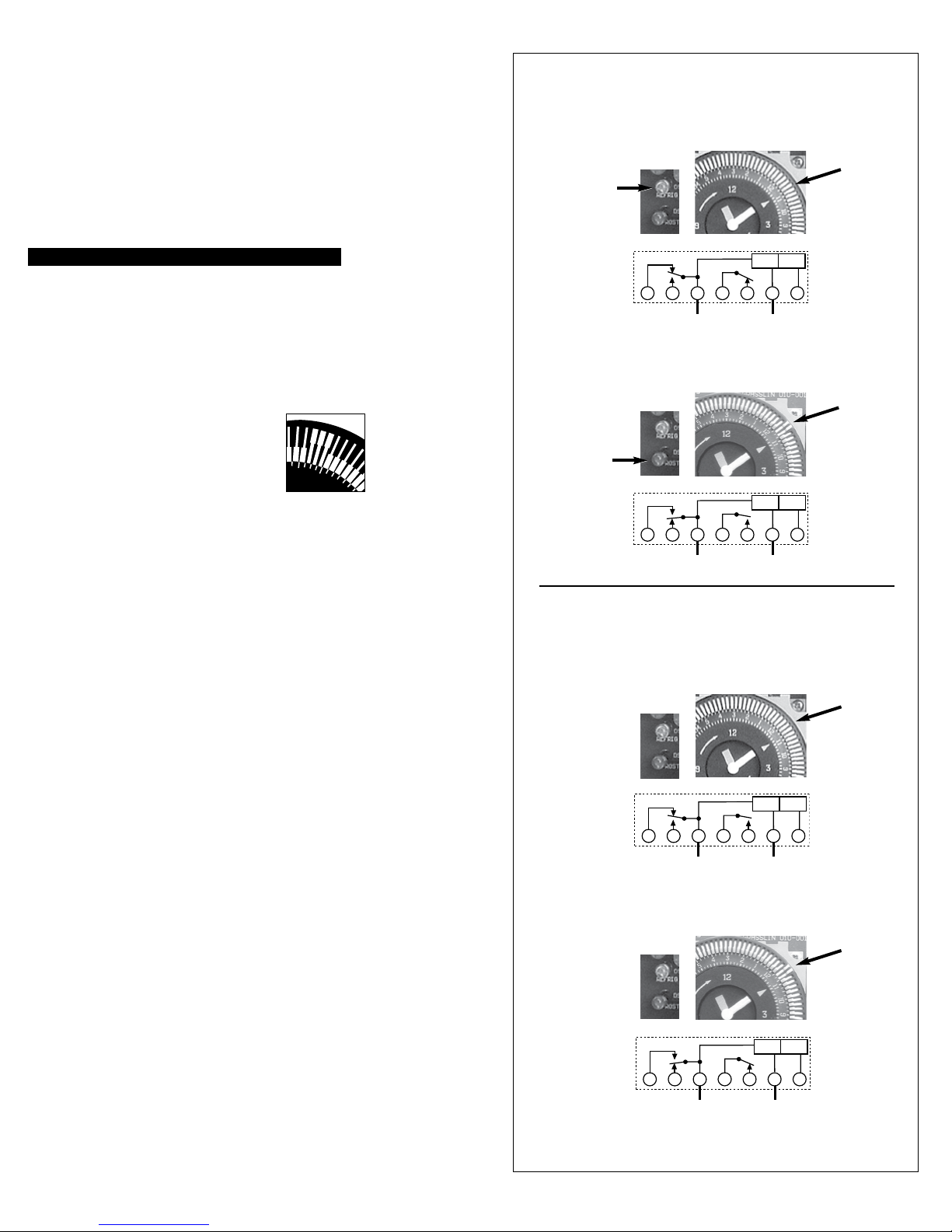
DTAV40 TRIPPERS
M ODE A
MODE A
Setting the Time of Day:
Rotate the timer dial clockwise to align the triangle on the
inner dial with the desired time. The triangle represents the
current time on the timer.
NOTE: The AM and PM locations on the wheel represent 6
AM and 6 PM. For example, if the triangle points to the 7
after PM, then the current time is 7 PM. If the triangle
points to the 5 before PM, then the current time is 5 AM.
DO NOT ROTATE MINUTE HAND COUNTER-CLOCKWISE
Setting Defrost Times:
Follow this procedure to configure defrost times.
1. On the timer wheel, choose a defrost starting time.
2. Slide the tripper upward that is directly above the desired
time. The timer will initiate a 15 minute defrost at the
configured time.
3. To increase the duration of the defrost,
slide up the trippers that are adjacent to the
starting time.
8
7
A
NOTE: Each tripper on the time wheel
represents 15 minutes. For example, to set a 45-minute
defrost, slide the two trippers adjacent to the starting time.
NOTE: The AM and PM locations on the wheel represent 6
AM and 6 PM.
“Green” LED ON
“1 & F” Make
“1 & 3” Break
“Red” LED ON
“1 & F” Break
“1 & 3” Make
In Refrigeration Mode
Arrow on timer points to current time.
CONTROL
TERMINATE
POWER
INPUT
1 2
3
F
L1 L2/N
4XN
In Defrost Mode
Arrow on timer points to current time.
CONTROL
TERMINATE
POWER
INPUT
1 2
3
F
L1 L2/N
4XN
Trippers are “IN”
Indicates
Refrigeration
“2 & 4” Make
Trippers are “OUT”
Indicates
Defrost
“2 & 4” Break
4. Repeat steps 1 through 3 as necessary to configure
multiple defrost times for a given day.
APPLICATION
The DTAV40 Defrost Timer is equivalent in function, terminal identification
(with appropriate terminal block label attached), and wiring to the Paragon
8140 and Precision 6140 series Defrost Timers. The DTAV40 may also be
used to replace Paragon 8040 and Precision 6040 series time terminated
defrost timers. With the addition of a remote pressure switch, the DTAV40 can
replace the Paragon 8240 series pressure terminated defrost timers.
Defrosts will be initiated by programming the timer, which will accept from 1
to over 24 defrost initiation settings per day at 15 minute intervals (8:00 AM,
8:15 AM, 8:30 AM, etc)
Defrost duration is settable in 15 minute intervals from a minimum of 15
minutes up to several hours. The defrost duration determines the termination
time. In standard configuration, the contacts between terminals 1 and 3 are
normally open and closed during a defrost to energize defrost heaters; the
contacts between terminals 2 and 4 are normally closed with S1 in “A”
position and open during a defrost to de-energize refrigeration and fans.
DTAV40 Time Initiated, Remote Temperature,
Pressure or Time Terminated:
Used in electric or hot gas defrost applications where the defrost is
terminated when the coil is frost free, as sensed by a temperature or
pressure switch, even though the defrost programmed termination time
has not been reached. The time termination functions as a fail-safe and will
terminate the defrost if the temperature or pressure switch fails to do so. The
temperature or pressure switch on the refrigeration coil has contacts which
close on a temperature or pressure rise above freezing, indicating
that frost and ice have melted from the coil. Typically a wide differential
SPDT temperature switch is used with it’s normally closed contacts wired to
the fans thereby delaying the fans from coming on until the coil temperature
has dropped back to below freezing. In most applications, the contacts at
terminals 2 and 4 are normally closed with S1 in “A” position and control the
fans and refrigeration equipment or compressor. For hot gas defrost, or for
double pole switching, contacts 2 and 4 may be configured as normally open
by selecting mode “B”. Refer to wiring diagrams 1 thru 10 for
additional detail.
DTAV40 TRIPPERS
DTAV40 TROUBLESHOOTING GUIDE
MODE B
MODE B
In Refrigeration Mode
Arrow on timer points to current time.
Trippers are “IN”
Indicates
Refrigeration
Both LED’s OFF
CONTROL
TERMINATE
POWER
“1 & F” Make
“1 & 3” Break
1 2
3
F
L1 L2/N
INPUT
“2 & 4” Break
4XN
In Defrost Mode
Arrow on timer points to current time.
Both LED’s ON
“1 & F” Break
“1 & 3” Make
Trippers are “OUT”
CONTROL
TERMINATE
POWER
INPUT
1 2
3
F
4XN
Indicates
Defrost
“2 & 4” Make
Note: It is necessary to apply power across terminals 1&N
in order to perform electrical test.
Page 3
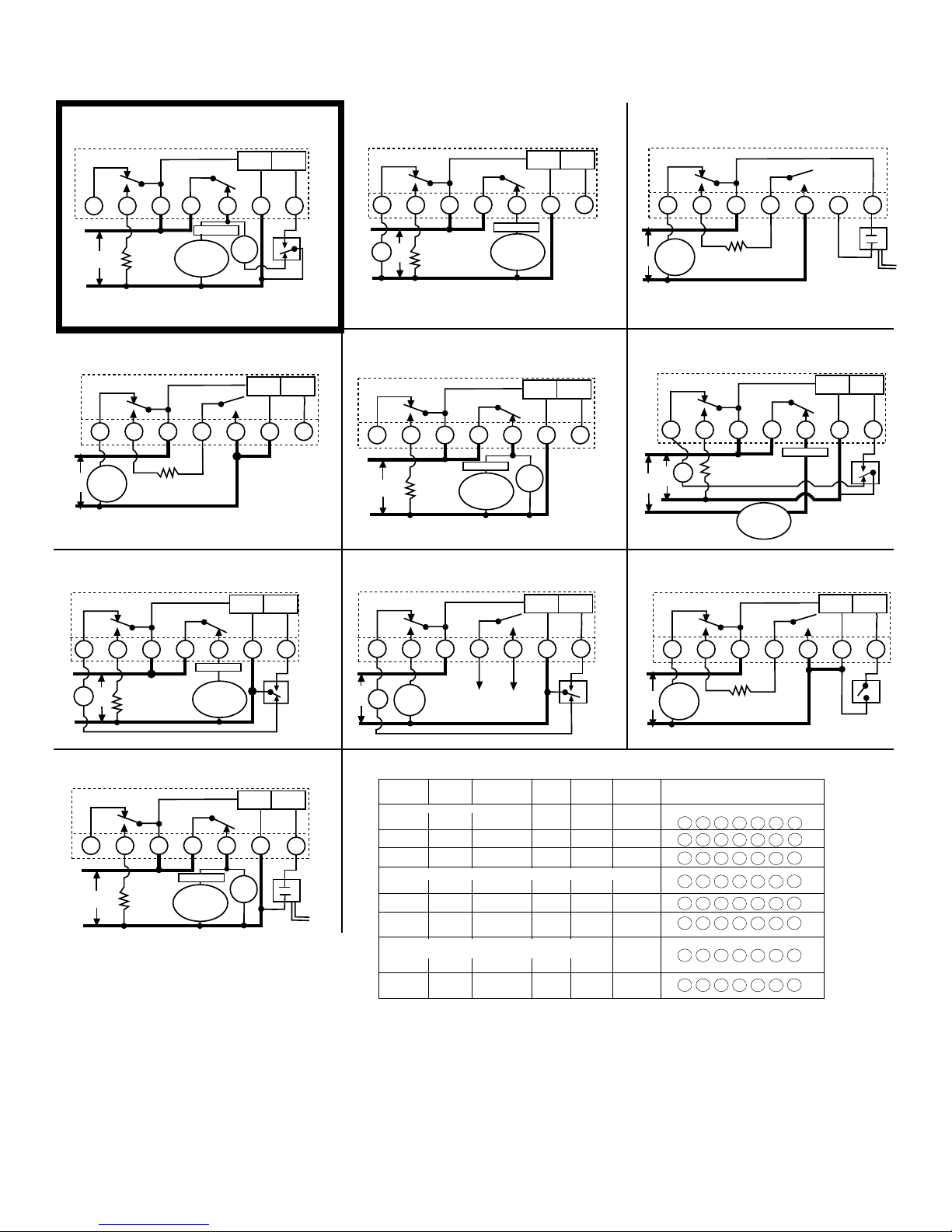
All switch positions are shown in refrigeration cycle operation, and change position upon initiation of a defrost.
WIRING LEGENDS
DTAV40 - TYPICAL WIRING DIAGRAMS
8145 Replacement
1
Mode A - No Label Required
2
1
3
F
L1
DEFROST
LINE
HEATER
THERMOSTAT
COMPRESSOR
OR
SOLENOID VALVE
OR
CONTACTOR COIL
4
FAN
MOTOR
L2
DEFAULT (Out of the Box)
8047 Replacement–Double Pole Switching
4
Mode B with 8047
N
L1
SOLENOID
VALVE
OR
LINE
CONTACTOR
L2
8141 Replacement
7
Mode A with 8141
1
Terminal Block Label Applied
3
DEFROST
HEATER
2
4
Terminal Block Label Applied
CONTROL
POWER
CONTROL
POWER
CONTROL
POWER
N
TERMINATE
INPUT
TERMINATE
INPUT
2
TERMINATE
INPUT
X
TERMINATION
THERMOSTAT
W/FAN DELAY
8047
LABEL
8041 Replacement
2
Mode A with 8041
N
L1
FAN
LINE
L2
8045 Replacement
5
Mode A with 8045
3
F
L1
LINE
L2
8143 Replacement
8
Mode B with 8143
1
DEFROST
DEFROST
HEATER
Terminal Block Label Applied
2
3
THERMOSTAT
COMPRESSOR
SOLENOID VALVE
HEATER
1-N
CONTACT
Terminal Block Label Applied
2
4 X
THERMOSTAT
COMPRESSOR
OR
SOLENOID VALVE
OR
CONTACTOR COIL
Terminal Block Label Applied
CONTROL
POWER
4 X
OR
OR
OR COIL
CONTROL
POWER
FAN
MOTOR
CONTROL
POWER
TERMINATE
INPUT
TERMINATE
INPUT
TERMINATE
INPUT
8041
LABEL
8045
LABEL
8247 Replacement–Double Pole Switching
3
Mode B with 8247 Terminal Block Label Applied
3
N
1
2
L1
SOLENOID
LINE
CONTACTOR
VALVE
OR
DEFROST
HEATER
L2
120V Fan & Defrost Heater; 240V Compressor
6
Mode A - No Label Required
3
F
2
1
L1
DEFROST
FAN
HEATER
120V
240V
N
L2
8143 Replacement–Double Pole Switching
9
Mode B with 8143 Terminal Block Label Applied
COMPRESSOR
OR
SOLENOID VALVE
OR
CONTACT
OR COIL
4
4
THERMOSTAT
CONTROL
POWER
CONTROL
POWER
Xp
PRESSURE
SWITCH
N
TERMINATE
INPUT
TERMINATE
INPUT
p
X
TERMINATION
THERMOSTAT
8247
LABEL
W/FAN
DELAY
8143
LABEL
L1
TERMINATION
THERMOSTAT
W/FAN DELAY
L2
Terminal Typical
5
2
4
1, 6
7
8, 9
See Note 1
10
3
SOLENOID
LINE
CONTACTOR
1
VALVE
3
N
OR
DEFROST
HEATER
F
3
1-N
2
4
N
1
3
2
4
N
1
3
4
2
F
3
1
2
4
N
1
3
2
4
1
N
3
4
2
F
3
1-N
2
4
N
1
3
2
4
2
4
X
TERMINATION
THERMOSTAT
X
X
2
X
N
X
X
p
Xp
p
Xp
L1
L2
10
L1
L2
N
1
FAN
LINE
8245 Replacement
Mode A with 8245
F
LINE
DEFROST
HEATER
3
DEFROST
HEATER
2
3
1-N
4
THERMOSTAT
COMPRESSOR
OR
SOLENOID VALVE
OR
CONTACT
Terminal Block Label Applied
2
THERMOSTAT
COMPRESSOR
OR
SOLENOID VALVE
OR
CONTACTOR COIL
OR COIL
4
FAN
MOTOR
X
CONTROL
POWER
Xp
TERMINATE
INPUT
8141
LABEL
TERMINATION
THERMOSTAT
W/FAN DELAY
8245
p
LABEL
PRESSURE
SWITCH
1
3
N
2
4
X
L1
HOT
GAS
FAN
LINE
VALVE
L2
Paragon Precision GRASSLIN S1 Mode Ident. Wiring Terminal Layout
Model Model Model Selector Label Diagram
TIME INITIATED, TIME TERMINATED
8045 6045 DTAV40 A 8045
8041 6041 DTAV40 A 8041
8047 6047 DTAV40 B 8047
TIME INITIATED, REMOTE TEMPERATURE OR PRESSURE TERMINATED
8145 6145 DTAV40 A None
8141 6141 DTAV40 A 8141
8143 --- DTAV40 B 8143
TIME INITIATED, PRESSURE TERMINATED
(Separate Pressure Switch Required - see instructions)
8245 --- DTAV40 A 8245
8247 --- DTAV40 B 8247
CONNECT ACROSS
COMPRESSOR
THERMOSTA
T
REPLACING EXISTING DEFROST TIMERS
The DTAV40 will replace all models of Paragon 8040, 8140,8240 Series or Precision 6040, 6140 Series and all prior Grasslin Defrost Timer models.
TERMINAL IDENTIFICATION:
The standard DTAV40 terminal identification is identical to the Paragon 8145 with the addition of the “F” terminal. Terminal identification labels are provided for the other models to be
placed over the printed numbers on the printed circuit board. From the table above, select the proper label, apply to printed circuit board and wire per the original wiring or the wiring
diagrams indicated.
“F” TERMINAL:
The DTAV40 contains a normally closed contact between terminals 1 and F. This terminal may be used to switch the fans off during a defrost rather than terminals 2 and 4. For hot gas
defrost applications, with the mode switch set to position “B”, the fans may be connected to terminal “F”.
8143 Replacement: When replacing a Paragon 8143, wire the termination thermostat to terminal X of the DTAV40 (with the 8143 label attached), and the adjacent blank terminal. The
Paragon timers are wired to terminal X and the blank terminal. If the termination thermostat is wired to terminal N of the DTAV40 temperature termination will not occur and may result
in burnout of the DTAV40. See wiring diagrams 8 & 9.
8240 SERIES REPLACEMENT: The DTAV40 may be used to replace the Paragon 8240 series defrost timers with integral pressure termination by the addition of a remote pressure
switch wired to terminals Xp and p of the DTAV40 (with an 8240 series terminal label applied). There must be no external voltage connected to the pressure switch. Set pressure
switch cut-in to the same value as set on the Paragon defrost timer being replaced. Set cut-out 6 to 14 psi below cut-in. See wiring diagrams 10 and 3.
8143
LABEL
Page 4

Instrucciones de
Paragon Precision
INICIADO POR HORA, FINALIZADO POR HORA
Grasslin
instalación y operación
Temporizadores de descongelación de 40 A y voltaje automático, iniciados por hora y
finalizados por temperatura, hora o presión de la serie DTAV40
ADVERTENCIA
Riesgo de incendio o descarga eléctrica
• Desconecte la energía desde los disyuntores o desconecte los interruptores antes de realizar la instalación o el
mantenimiento.
• Es posible que requiera más de un disyuntor o interruptor de desconexión para desenergizar el equipo antes de
realizar mantenimiento.
• La instalación y el cableado se deben realizar de acuerdo con los requisitos del Código Eléctrico Nacional y Local.
• Para cargas de 40 A, use cable AWG n.º 8, clasificado para 90 °C mín.
• La unión entre las conexiones de los conductos no es automática y se debe proporcionar como parte de la
instalación.
• Cuando reemplace un temporizador que tenga un soporte de metal, reemplace el soporte por uno no metálico. (Se
recomienda el modelo DT-B de Intermatic).
• Se deben usar ejes de conducto pluvífugos o para ubicaciones húmedas que cumplan los requisitos de la norma
UL514B (estándar para piezas para conductos y cajas de distribución) en ubicaciones al aire libre.
AVISO
Riesgo de daños al temporizador
• Gire el disco del temporizador sólo en la dirección de las agujas del reloj.
• No mueva las agujas del reloj del temporizador. Hacerlo puede dañar el temporizador.
Interruptor de selección de modo (S1)
INSTALACIÓN
1. Abra la puerta y retire la cubierta interior de protección liberando el
pestillo de resorte del fondo (Figura 1). La cubierta se saca fácilmente
en la caja metálica tipo 1 (Figura 4).
2. Aplique la identificación de terminal y etiquetas de puerta
correspondiente. Consulte las instrucciones del kit de conversión.
3. Retire el mecanismo temporizador liberando el pestillo del circuito del
MONTAJE DE SOPORTE
(elemento comercializable DT-B)
CONSULTE EL AVISO DE
REEMPLAZO DE SOPORTE
CAJA TIPO 3R UL
Ajuste de la selección de modo (consulte Interruptor PLD S1, la tabla y las instrucciones a continuación).
CAJA TIPO 1 UL
SEPARADO EN EL EMPAQUE
SELECCIÓN DE MODO (INTERRUPTOR PLD S1):
Primero determine cuál modelo será reemplazado (Grasslin o sus
competidores). El interruptor PLD de selección de modo (que se
encuentra en el lado inferior derecho de la placa) determina la configuración de los terminales 2 y 4. En la posición “A”, los terminales
normalmente están cerrados y se abren durante la descongelación. En
la posición “B” los terminales 2 y 4 normalmente están abiertos y se cierran
durante la descongelación. Seleccione la posición adecuada de la tabla
que se encuentra a continuación y los diagramas de cableado que se
indican. Para seleccionar un modo, simplemente deslice el interruptor del
siguiente modo:
Modo A - posición del interruptor hacia arriba;
fondo (Figura 1). El mecanismo temporizador viene separado en la caja
metálica tipo 1 (Figura 4).
4. Seleccione los orificios ciegos que desee usar. Inserte un destornillador
en la ranura para retirar el orificio ciego interior de 1/2pulg. y presione
cuidadosamente para soltar el orificio ciego. Retire la tapa. Si se necesita
un orificio ciego de 3/4pulg., retire el anillo exterior con un alicate luego
de retirar el orificio ciego de 1/2pulg. Alise los bordes con un cuchillo si
fuera necesario, solo en la caja de plástico.
5. Coloque la caja en la ubicación de montaje que desee y marque los tres
orificios de montaje (consulte la Figura 2, para obtener más información
sobre el tipo 3R y la Figura 3, para obtener más información sobre el tipo
1 que se muestra a continuación). Primero instale el tornillo superior
en la superficie de montaje y la caja colgante en la cabeza del tornillo a
través del ojo de la cerradura; luego atornille los dos tornillos restantes
en los orificios del fondo.
6. Conexión a tierra: Termine todos los cables a tierra en el terminal de
tierra en la parte inferior de la caja.
7. Vuelva a instalar el temporizador en la caja.
8. Reemplace la cubierta interior de protección.
Modo B - posición del interruptor hacia abajo;
Nota: Cuando esté seleccionado el modo “B”
DTAV40 funcionará del siguiente modo:
Modo de refrigeración - Las luces LED ROJOS y
VERDES se APAGARÁN (1 y 3, y 2 y 4 se
Cubierta
interior de
protección
desconectan, mientras 1 y F se conectan)
Modo de descongelación - Los LED ROJOS
Y VERDES se ENCIENDEN (1 y 3, y 2 y 4 se
conectan, mientras 1 y F se desconectan)
Selección
de modo
INICIADO POR HORA, SEÑAL REMOTA DE FINALIZACIÓN
POR TEMPERATURA O PRESIÓN
INICIADO POR HORA, FINALIZADO POR PRESIÓN
[Se necesita un presostato separado (consulte las instrucciones)]
Diagrama
de cableado
10,32 cm
(4-1/16 pulg.)
Pestillo de resorte
Pestillo del circuito impreso (PCB)
ESPECIFICACIONES:
Clasificación máxima de contacto de interruptor:
Resistivo de 40 amperios de 120 a 240 V CA
2HP a 240 V CA; 1 HP a 120 V CA
CONEXIONES DE CABLEADO:
Terminales del cárter de tornillo, A un cable AWG n˚8
CLASIFICACIONES AMBIENTALES:
Rango de temperatura de funcionamiento:
-40˚C hasta 40˚C (-40˚F hasta 104˚F)
Humedad de funcionamiento: 0 a 95% HR, no
condensante
VIDA ELÉCTRICA:
50.000 Operaciones a carga completa
DIMENSIONES:
22,3 x 16,8 x 7,4 cm (8,795 x 6,631 x 2,935 pulg.)
(Altura x Ancho x Profundidad)
PESO DE EMBARQUE: 1,36 kg (3 libras)
APROBACIONES DE AGENCIAS: INCLUIDA EN LISTA DE UL
Mecanismo temporizador
6,35 cm
(2-1/2 pulg.)
Caja tipo 3R
Figura 1
19,69 cm
(7-3/4 pulg.)
7 ¾"
Pestillo del circuito
impreso (PCB)
15,56 cm
(6-1/8 pulg.)
6,35 cm
(2-1/2 pulg.)
Terminal de tierra
Caja tipo 3R
Figura 2
Mecanismo temporizador
Referencia
DTAV40 Substituye sobre 40 modelos
12,7 cm (5 pulg.)
5"
Caja tipo 1
Figura 3
Cubierta
interior de
protección
Caja tipo 1
Figura 4
Page 5

M
PROGRAMACIÓN DE MODELOS SINCRÓNICOS Y
L1 L2/N
DE CUARZO
Siga las instrucciones descritas en las secciones que se presentan a
continuación para programar el temporizador DTAV40.
Ajuste de la hora del día:
Gire el disco del temporizador en la dirección de las agujas del reloj
para alinear el triángulo del disco interno con la hora deseada. El
triángulo representa la hora actual del temporizador.
NOTA: Las ubicaciones a.m. y p.m. de la rueda representan las
6:00 a.m. y las 6:00 p.m. Por ejemplo, si el triángulo apunta hacia
el número 7, después de p.m., la hora actual es 7:00 p.m. Si el
triángulo apunta hacia el número 5, antes de p.m., la hora actual es
5:00 a.m.
NO GIRE EL MINUTERO EN EL SENTIDO CONTRARIO AL DE LAS AGUJAS DEL RELOJ
Ajuste de las horas de descongelación:
Siga este procedimiento para configurar las horas de descongelación.
1. En la rueda del temporizador, elija una hora de inicio de la
descongelación.
2. Deslice el disparador hacia arriba de forma que quede
directamente sobre la hora deseada. El temporizador
iniciará una descongelación de 15 minutos a
la hora configurada.
3. Para aumentar la duración del la descongelación,
deslice hacia arriba los disparadores adyacentes
a la hora de inicio.
NOTA: Cada disparador en la rueda de tiempo
representa 15 minutos. Por ejemplo, para configurar una
8
7
A
descongelación de 45 minutos, deslice los dos disparadores
adyacentes a la hora de inicio.
NOTA: Las ubicaciones a.m. y p.m. de la rueda representan las 6:00
a.m. y las 6:00 p.m.
4. Repita los pasos del 1 al 3, según sea necesario, para configurar
múltiples horas de descongelación para un determinado día.
APLICACIÓN
El temporizador de descongelación DTAV40 es equivalente a las series de
temporizadores Paragon 8140 y Precision 6140 en términos de función,
identificación de terminal (con una etiqueta adecuada de bloque de terminal
adjunta) y cableado. El DTAV40 también se puede utilizar para reemplazar la
serie de temporizadores de descongelación finalizados por hora Paragon 8040
y Precision 6040. Con la adición de un presostato remoto, el DTAV40 puede
reemplazar la serie de temporizadores de descongelación finalizados por
presión Paragon 8240. Las descongelaciones serán iniciadas al programar el
temporizador, el cual aceptá de 1 a más de 24 configuraciones de iniciación
de descongelación por día en intervalos de 15 minutos (8:00a.m., 8:15a.m.,
8:30 a.m., etc.). La Duración de descongelación se puede ajustar en intervalos
de 15 minutos, a partir de un mínimo de 15 minutos hasta varias horas. La
duración de descongelación determina la hora de término. Normalmente, en
una configuración estándar, los contactos entre los terminales 1 y 3 se abren
y cierran durante una descongelación para energizar los calefactores de
descongelación; los contactos entre los terminales 2 y 4 se cierran con S1 en
la posición “A” y se abren durante una descongelación para desenergizar la
refrigeración y los ventiladores.
DTAV40 iniciado por tiempo, señal remota de finalización por
temperatura, presión u hora:
Se usa en aplicaciones de descongelación eléctrica o a gas caliente donde se
finaliza la descongelación en el momento en que la bobina se encuentre libre
de escarcha, lo cual se detecta mediante un presostato o termostato, incluso
si no se ha cumplido la hora de término programada de la descongelación.
La hora de término funciona como un modo a prueba de fallos y finalizará la
descongelación en el caso de que el termostato o el presostato no funcionen.
El termostato o el presostato en la bobina de refrigeración tienen contactos que
se cierran cuando una temperatura o presión superan a la de congelación, lo
que indica que la escarcha y el hielo se derritieron de la bobina. Típicamente, se
utiliza un termostato de amplio diferencial unipolar de doble tiro (SPDT), en el
cual sus contactos se encuentran normalmente conectados a los ventiladores,
lo cual retrasa el comienzo de los ventiladores hasta que la temperatura de la
bobina haya caído a temperaturas bajo el nivel de congelación. En la mayoría
de las aplicaciones, los contactos en los terminales 2 y 4 se encuentran
normalmente cerrados con S1 en la posición “A” y controlan los ventiladores
y el equipo de refrigeración o el compresor. En el caso de la descongelación
con gas caliente o de una conmutación bipolar, los contactos 2 y 4 se pueden
configurar como normalmente abiertos mediante la selección del modo “B”.
Consulte los diagramas de cableado 1 al 10 para conocer detalles adicionales.
GUÍA DE SOLUCIÓN DE
DISPARADORES DEL DTAV40
PROBLEMAS DEL DTAV40
MODO
A
MODO A
En modo de refrigeración
El puntero en el temporizador apunta a la hora actual.
LED “Verde”
encendido
Conexión
de “1 y F”
Desconexión
de “1 y 3”
POTENCIA
TERMINAL
DE CONTROL
DE ENTRADA
1 2
3
F
L1 L2/N
4XN
Los disparadores
están “Adentro”,
lo que indica
refrigeración
Conexión
de “2 y 4”
En modo de descongelación
El puntero en el temporizador apunta a la hora actual.
LED “Rojo”
Encendido
Desconexión
de “1 y F”
Conexión
de “1 y 3”
F
GUÍA DE SOLUCIÓN DE
DISPARADORES DEL DTAV40
PROBLEMAS DE DTAV40
1 2
3
L1 L2/N
MODO
4XN
B
POTENCIA
DE CONTROL
TERMINAL
DE ENTRADA
Los disparadores
están “Afuera”,
lo que indica
descongelación
Desconexión
de “2 y 4”
MODO B
En modo de refrigeración
El puntero en el temporizador apunta a la hora actual
Los disparadores
están “Adentro”,
lo que indica
Ambos LED
apagados
TERMINAL
Conexión
de “1 y F”
Desconexión
de “1 y 3”
1 2
3
F
L1 L2/N
POTENCIA
DE CONTROL
4XN
DE ENTRADA
En modo de descongelación
El puntero en el temporizador apunta a la hora actual.
Ambos
LED ENCENDIDOS
POTENCIA
Desconexión
de “1 y F”
Conexión
de “1 y 3”
1 2
3
F
DE CONTROL
4XN
TERMINAL
DE ENTRADA
Nota: Es necesario aplicar potencia entre los terminales
1 y N para realizar una prueba eléctrica.
refrigeración
Desconexión
de “2 y 4”
Los disparadores
están “Afuera”,
lo que indica
descongelación
Conexión
de “2 y 4”
Page 6

DTAV40 - DIAGRAMAS TÍPICOS DE CABLEADO
TERMOSTATO
COMPRESOR
O VÁLVULA DE
SOLENOIDE
O CONTACTOR
DE BOBINA
CALEFACTOR DE
DESCONGELACIÓN
L1
L2
1
2
4 X
Reemplazo de 8141
Modo A con etiqueta aplicada del bloque
de terminales 8141
2
8041
ETIQUETA
3
LÍNEA
VENTILADOR
N
L1
L2
L1
L2
4
Reemplazo 8247, conmutación bipolar
Modo B con etiqueta aplicada del bloque de
terminales 8247
8247
ETIQUETA
3
CALEFACTOR DE
DESCONGELACIÓN
LÍNEA
VÁLVULA
DE SOLENOIDE
O CONTACTOR
N
2
1
p
PRESOSTATO
Xp
LEYENDAS DE CABLEADO
Se muestran todas las posiciones de interruptores en la operación de ciclo de refrigeración y
cambian su posición al momento de iniciar una descongelación.
Reemplazo
Modo A: No necesita etiqueta
1
F
L1
LÍNEA
L2
8145
3
CALEFACTOR DE
DESCONGELACIÓN
POTENCIA
DE CONTROL
2
1
TERMOSTATO
COMPRESOR
O VÁLVULA DE
SOLENOIDE
O CONTACTOR
DE BOBINA
4
MOTOR
DEL
VENTILADOR
N
CONFIGURACION DE FABRICA
(Fuera de la caja)
Reemplazo 8047, conmutación bipolar
4
Modo B con etiqueta aplicada del bloque
de terminales 8047
3
1
N
VÁLVULA
DE SOLENOIDE
LÍNEA
O CONTACTOR
CALEFACTOR DE
DESCONGELACIÓN
POTENCIA
DE CONTROL
2
4
2
TERMINAL
DE ENTRADA
X
TERMINAL
DE ENTRADA
TERMINAL DE
TERMOSTATO
CON RELÉ DE
VENTILADOR
ETIQUETA
8047
POTENCIA
DE CONTROL
Reemplazo de 8045
5
Modo A con etiqueta aplicada del bloque de
terminales 8045
POTENCIA
DE CONTROL
1-N
2
TERMOSTATO
COMPRESOR
O VÁLVULA DE
SOLENOIDE
O CONTACTOR
DE BOBINA
4 X
MOTOR
DEL
VENTILADOR
L1
L2
F
LÍNEA
3
CALEFACTOR DE
DESCONGELACIÓN
TERMINAL
DE ENTRADA
TERMINAL
DE ENTRADA
ETIQUETA
8045
3
Ventilador y calefactor de descongelación de
6
120 V; compresor de 240 V
Modo A: No necesita etiqueta
3
F
2
1
L1
CALEFACTOR DE
VENTI-
LADOR
DESCONGELACIÓN
120V
240V
N
L2
COMPRESOR
O VÁLVULA DE
SOLENOIDE
O CONTACTOR
DE BOBINA
4
TERMOSTATO
POTENCIA
DE CONTROL
N
TERMINAL
DE ENTRADA
X
TERMINAL DE
TERMOSTATO
CON RELÉ DE
VENTILADOR
Reemplazo 8141
7
Modo A con etiqueta aplicada del bloque de
terminales 8141
POTENCIA
TERMINAL
DE CONTROL
DE ENTRADA
ETIQUETA
8141
TERMINAL DE
TERMOSTATO
CON RELÉ DE
VENTILADOR
N
1
L1
VENTILADOR
CALEFACTOR DE
LÍNEA
DESCONGELACIÓN
2
3
TERMOSTATO
COMPRESOR
O VÁLVULA DE
SOLENOIDE
O CONTACTOR
L2
Reemplazo 8245
10
Modo A con etiqueta aplicada del bloque de
4
DE BOBINA
X
terminales 8245
POTENCIA
TERMINAL
DE CONTROL
DE ENTRADA
ETIQUETA
p
1-N
2
TERMOSTATO
COMPRESOR
O VÁLVULA DE
SOLENOIDE
O CONTACTOR
DE BOBINA
3
F
L1
LÍNEA
CALEFACTOR
DE DESCONGELACIÓN
L2
REEMPLAZO DE TEMPORIZADORES DE DESCONGELACIÓN EXISTENTES
El DTAV40 reemplazará todos los modelos de serie Paragon 8040, 8140, la serie 8240 o la serie Precision 6040, 6140 y todos los modelos de temporizador de descongelación Grasslin
anteriores.
IDENTIFICACIÓN DE TERMINAL: La identificación de terminal estánder del DTAV40 es idéntica a la del Paragon 8145, con la adición del terminal “F”. Se entregan otras etiquetas de identificación
de terminales para los otros modelos a ser ubicados sobre los números impresos en el tablero de circuitos impresos. En la tabla superior, seleccione la etiqueta adecuada, aplíquela al tablero de
4
MOTOR
DEL
VENTILADOR
Xp
8245
PRESOSTATO
Reemplazo de 8143
8
Modo B con etiqueta aplicada del bloque de
terminales 8143
3
1
N
4
L1
VÁLVULA
L2
VENTI-
DE GAS
LADOR
LÍNEA
CALIENTE
Modelo
Paragon
INICIADO POR HORA, FINALIZADO POR HORA
INICIADO POR HORA, SEÑAL REMOTA DE FINALIZACIÓN
POR TEMPERATURA O PRESIÓN
INICIADO POR HORA, FINALIZADO POR PRESIÓN
[Se necesita un presostato separado (consulte las instrucciones)]
8247 --- DTAV40 B 8247
CONECTE A LO
LARGODEL TERMOSTATO
DEL COMPRESOR
Modelo
Precision
8045 6045 DTAV40 A 8045
8041 6041 DTAV40 A 8041
8047 6047 DTAV40 B 8047
8145 6145 DTAV4 A Ninguna
8141 6141 DTAV40 A 8141
8143 --- DTAV40 B 8143
8245 --- DTAV40 A 8245
GRASSLIN
POTENCIA
TERMINAL
DE CONTROL
DE ENTRADA
ETIQUETA
modo S1
8143
TERMINAL DE
TERMOSTATO
CON RELÉ DE
VENTILADOR
Etiqueta de
identificación
de terminal
2
X
LEYENDAS DE CABLEADO
Modelo
Selector de
Reemplazo de 8143, conmutación bipolar
9
Modo B con etiqueta aplicada del bloque de
terminales 8143
3
1
N
4
L1
SOLENOID
LÍNEA
L2
Diagrama de
cableado típico
5
2
4
1, 6
7
8, 9
Consulta la Nota 1
10
3
VALVE
OR
CONTACTOR
*See Note 1
Esquema de terminal
F
3
N
1
N
1
F
3
N
1
1
N
F
3
N
1
CALEFACTOR DE
DESCONGELACIÓN
1-N
2
4
3
2
4
3
4
2
1
2
4
3
2
4
3
4
2
1-N
2
4
3
2
4
X
X
2
N
X
X
Xp
Xp
POTENCIA
TERMINAL
DE CONTROL
DE ENTRADA
2
X
X
p
p
circuitos impresos y conéctela a través del cableado original o los diagramas de cableado indicados.
TERMINAL “F”: El DTAV40 contiene un contacto normalmente cerrado entre los terminales 1 y F. Este terminal puede ser utilizado para apagar los ventiladores durante una descongelación en
vez de los terminales 2 y 4. Para aplicaciones de descongelación a gas caliente, con el modo de cambio en posiciôn “B”, los ventiladores pueden ser conectados al terminal “F”.
Reemplazo de 8143: Al remplazar una unidad Paragon 8143, cablee el termostato de término al terminal X del DTAV40 (con la etiqueta de 8143 adjunta) y al terminal vacío adyacente. Los
temporizadores Paragon se cablean al terminal X y al terminal vacío. Si el termostato de término está cableado al terminal N del DTAV40, no ocurrirá la terminación de la temperatura y puede
causar que el DTAV40 se queme. Consulte los diagramas de cableado 8 y 9.
REEMPLAZO DE LA SERIE 8240: El DTAV40 se puede usar para reemplazar temporizadores de descongelación con término de presión integral de la serie 8240 de Paragon agregando un
presostato remoto cableado en las terminales Xp y p del DTAV40 (con una etiqueta de terminal de la serie 8240 aplicada). El presostato no debe tener conectado voltaje externo. Configure el conjuntor del presostato en el mismo valor que está configurado en el temporizador de descongelación Paragon que esté reemplazando. Configure el disyuntor y 6 a 14 psi bajo el valor del conjuntor.
Consulte los diagramas de cableado 10 y 3.
ETIQUETA
8143
TERMINAL DE
TERMOSTATO
Page 7

Instructions d’installation
Paragon Precision
DÉCLENCHEMENT PAR HORLOGE, INTERRUPTION PAR HORLOGE
Grasslin
et d’utilisation
Série DTAV40 Minuterie de dégivrage 40A à tension automatique,
à déclenchement par horloge et interruption par température, pression ou horloge
AVERTISSEMENT
Risque d’incendie ou de choc électrique
• Débrancher l’alimentation au niveau des disjoncteurs ou des sectionneurs avant de procéder à l’installation
ou à l’entretien.
• Il peut être nécessaire d’ouvrir plusieurs disjoncteurs ou sectionneurs pour mettre le matériel hors tension
avant d’y travailler.
• L’installation et/ou le câblage doivent être conformes aux exigences du code de l’électricité en vigueur.
• Pour les charges de 40 A, utiliser du fil n°8 AWG classé 90°C min.
• La liaison entre les raccordements de conduits n’est pas automatique et doit être prévue dans le cadre de
l’installation.
• Lors du remplacement d’une minuterie à support métallique, remplacer ce support par un support non
métallique (de préférence par le modèle DT-B d’Intermatic).
• Pour les emplacements extérieurs, étanches à la pluie ou les emplacements mouillés, des entrées de conduit
qui sont conformes aux exigences de UL514B (norme pour les pièces de fixation pour conduit et boîtes de
sortie) doivent être utilisées.
AVIS
Risque de dommage à la minuterie
• Toujours tourner le cadran dans le sens horaire.
• Ne pas déplacer les aiguilles de l’horloge sur la minuterie. Déplacer les aiguilles de l’horloge peut endommager la minuterie.
Sélecteur de mode (S1)
INSTALLATION
1. Ouvrir la porte puis enlever le revêtement protecteur intérieur en dégageant
2. Apposer les étiquettes d’identification de borne et de porte correspondantes -
3. Enlever le mécanisme de la minuterie en dégageant le loquet PCB dans le bas
MONTAGE SUR SUPPORT
COFFRET UL DE TYPE 3R
COFFRET UL DE TYPE 1
(Article DT-B vendable)
VOIR L’AVIS SÉPARÉ DE
REMPLACEMENT DU SUPPORT
DANS L’EMBALLAGE
4. Sélectionner les alvéoles défonçables qui seront utilisées. Enlever l’intérieur
Régler la sélection de mode (Voir Interrupteur DIP S1, le tableau et les instructions ci-dessous).
SÉLECTION DE MODE (COMMUTATEUR DIP S1):
5. Placer le coffret dans l’emplacement de montage désiré et marquer les trois
Déterminer d’abord quel modèle doit être remplacé (Grasslin ou autre marque).
Le commutateur DIP de sélection de mode (sur le côté droit du circuit)
détermine la configuration du contact entre les bornes 2 et 4. En position A, ce
contact est normalement fermé (contact repos) et s’ouvre durant un dégivrage.
En position B, le contact 2-4 est normalement ouvert (contact travail) et se
ferme durant un dégivrage. Sélectionner la position qui convient depuis le
tableau ci-dessous et les schémas de câblage indiqués. Pour sélectionner le
mode, il suffit de coulisser le commutateur comme suit:
6. Mise à la terre : Terminer tous les fils de mise à la terre à la cosse de mise à
7 Réinstaller la minuterie dans le coffret.
8. Remettre le revêtement protecteur intérieur.
Mode A - commutateur en position haute;
Mode B - commutateur en position basse;
Remarque: Si le mode B est sélectionné, la
minuterie DTAV40 fonctionne comme suit:
Mode réfrigération - Voyants rouge et vert
éteints (contacts 1-3 et 2-4 ouverts, 1-F fermé)
Mode dégivrage - Voyants rouge et vert
allumés (contacts 1-3 et 2-4 fermés, 1-F ouvert)
DONNÉES TECHNIQUES :
Intensité maximale du commutateur à contact :
40 A résistifs sous 120 à 240 V c.a.
2 HP sous 240 V c.a. ; 1 HP sous 120 V c.a.
RACCORDEMENTS DE CÂBLES :
Bornes de connexion à vis. Conducteur jusqu’à n˚ 8 AWG
DONNÉES ENVIRONNEMENTALES :
Plage de température d’exploitation :
-40˚C à 40˚C (-40˚F à 104˚F)
Humidité d’exploitation : 0 à 95 % d’H.R. sans
condensation
DURABILITÉ ÉLECTRIQUE :
50 000 actionnements à pleine charge
DIMENSIONES :
223,4 x 168,4 x 74,5 mm (H x L x P)
POIDS D’EXPÉDITION : 1 360 g
HOMOLOGATION : LISTÉ UL
le loquet à ressort dans le bas (Figure 1). Le revêtement fléchit facilement sur
un boîtier métallique de Type 1 (Figure 4).
voir les instructions pour la trousse de modification.
(Figure 1). Le mécanisme de la minuterie se détache du coffret métallique de
Type 1 (Figure 4).
de 1/2 po de l’alvéole défonçable en insérant un tournevis dans la fente et
en défonçant soigneusement l’alvéole défonçable. Enlever la pastille. Si une
alvéole défonçable de 3/4 po est requise, enlever la bague extérieure avec des
pinces après avoir enlevé l’alvéole défonçable de 1/2 po. Adoucir les bords
avec un couteau si nécessaire, sur coffret en plastique seulement.
trous de montage (consulter la Figure 2 pour le Type 3R et la Figure 3 pour
le Type 1 ci-dessous). Commencer par installer la vis supérieure dans la
surface de montage et par suspendre le coffret sur la tête de vis à travers la
boutonnière; puis visser les deux vis restantes dans les trous du bas.
la terre au bas du coffret.
Mécanisme de minuterie
Capot
protecteur
intérieur
15,56 cm
(6-1/8 po)
6,35 cm
(2-1/2 po)
Sélection de mode Schéma câbl.
DÉCLENCHEMENT PAR HORLOGE, INTERRUPTION PAR
THERMO- OU MANOCONTACTEUR EXTERNE
DÉCLENCHEMENT PAR HORLOGE, INTERRUPTION PAR MANOCONTACTEUR
(nécessite un manocontacteur séparé - voir les instructions)
Correspondance
DTAV40 substitue plus de 40 modèles.
10,32 cm
(4-1/16 po)
Loquet à ressort
6,35 cm
(2-1/2 po)
12,7 cm (5 po)
5"
Coffret de Type 1
Figure 3
Loquet PCB
Coffret de Type 3R
Figure 1
19,69 cm
(7-3/4 po)
7 ¾"
Loquet PCB
Capot
protecteur
intérieur
Cose de terre
Coffret de Type 3R
Figure 2
Mécanisme de minuterie
Coffret de Type 1
Figure 4
Page 8

M
PROGRAMMER LES MODÈLES SYNCHRONE ET
L1 L2/N
QUARTZ
Suivre les instructions dans les sections ci-dessous pour programmer
la minuterie DTAV40.
Régler l’heure du jour :
Tourner le cadran de la minuterie dans le sens horaire pour aligner
le triangle sur le cadran intérieur avec l’heure désirée. Le triangle
représente l’heure actuelle sur la minuterie.
REMARQUE : Les emplacements AM et PM sur la roue représentent
6 AM et 6 PM. Par exemple, si le triangle pointe sur le 7 après PM,
alors l’heure actuelle est 7 PM. Si le triangle pointe sur le 5 avant
PM, alors l’heure actuelle est 5 AM.
NE PAS TOURNER L’AIGUILLE DES MINUTES DANS LE SENS ANTIHORAIRE
Régler les temps de dégivrage :
Suivre cette procédure pour configurer les temps de dégivrage.
1. Sur la roue de la minuterie, choisir l’heure de début du dégivrage.
2. Glisser le déclencheur vers le haut directement au dessus de
l’heure désirée. La minuterie initiera un dégivrage de 15 minutes à
l’heure configurée.
3. Pour augmenter la durée de dégivrage, glisser
vers le haut les déclencheurs qui sont adjacents
à l’heure de début.
REMARQUE : Chaque déclencheur sur la roue
représente 15 minutes. Par exemple, pour
régler un dégivrage de 45 minutes, glisser les
deux déclencheurs adjacents à l’heure de début.
REMARQUE : Les emplacements AM et PM sur la roue représentent
6 AM et 6 PM.
4. Répéter les étapes 1 à 3 pour configurer plusieurs temps de
dégivrage pour un jour donné.
8
7
A
GUIDE DE DÉPANNAGE DTAV40
Voyant vert
allumé
1-F fermé
1-3 ouvert
Voyant rouge
allumé
1-F ouvert
1-3 fermé
MODE A
En mode Réfrigération
Flèche de minuterie pointée sur l’heure courante.
ALIMENTATION
ENTRÉE
DE COMMANDE
D’INTERRUPTION
1 2
3
F
L1 L2/N
En mode Dégivrage
Flèche de minuterie pointée sur l’heure courante.
1 2
3
F
L1 L2/N
4XN
ALIMENTATION
DE COMMANDE
4XN
ENTRÉE
D’INTERRUPTION
Déclencheur
« rentré »
pour la
réfrigération
2-4 fermé
Déclencheur
« sorti »
pour le
dégivrage
2-4 ouvert
UTILISATION
La minuterie de dégivrage DTAV40 est équivalente par ses fonctions, par
l’identification des bornes (avec l’étiquette de bornier appropriée) et par son
câblage aux minuteries de dégivrage Paragon série 8140 et Precision série
6140. La DTAV40 peut également s’utiliser pour remplacer les minuteries de
dégivrage à interruption par horloge Paragon série 8040 et Precision série
6040. Avec l’ajout d’un manocontacteur externe, la DTAV40 peut remplacer
les minuteries de dégivrage à interruption manométrique Paragon série
8240. Les dégivrages sont déclenchés par la programmation de l’horloge,
qui accepte 1 à plus de 24 déclenchements de dégivrage par jour par
intervalles de 15 minutes (8h00, 8h15, 8h30, etc.). La durée de dégivrage est
réglable par intervalles de 15 minutes, depuis un minimum de 15 minutes
jusqu’à plusieurs heures. La durée du dégivrge détermint l’heure de fin du
dégivrage. En configuration standard, les contacts entre les bornes 1 et 3
sont normalement ouverts et se ferment durant un dégivrage pour activer
les réchauffeurs de dégivrage; les contacts entre les bornes 2 et 4 sont
normalement fermés si S1 est en position A et ouverts durant un dégivrage
pour désactiver la réfrigération et les ventilateurs.
DTAV40 à déclenchement par horloge et interruption par horloge,
thermostat ou manocontacteur externe :
Utilisé dans les applications de dégivrage électrique ou par gaz chaud où le
dégivrage s’arrêtte une fois que le serpentin est exempt de givre, ce qui est
détecté par un thermo-ou un manocontacteur, même si la durée de dégivrage
programmée n’est pas écoulée. L’interruption par horloge est une fonction de
sécurité intégrée qui met fin au dégivrage si cela n’est pas commandé par
le thermo-ou le manocontacteur. Le thermocontacteur ou manocontacteur
de serpentin de réfrigération comporte des contacts qui se ferment pour une
élévation de température ou de pression au-dessus du gel, indiquant que le
givre et la glace ont entièrement fondu du serpentin.
Généralement, un thermocontacteur SPDT (unipolaire bidirectionnel) à large
différentiel est utilisé, avec ses contacts normalement fermés raccordés
aux ventilateurs, ce qui retarde l’activation des ventilateurs jusqu’à ce que
la température du serpentin soit redescendu jusqu’en dessous du gel. Dans
lamajorité des cas, les contacts entre les bornes 2 et 4 sont normalement
fermés avec S1 en position A et ils commandent les ventilateurs et
l’équipement de réfrigération ou le compresseur. Pour le dégivrage par gaz
chaud ou pour la commutation bipolaire, les contacts entre 2 et 4 peuvent
être configurés pour être normalement ouverts en sélectionnant le mode B.
Voir les détails supplémentaires dans les schémas de câblage 1 à 10.
GUIDE DE DÉPANNAGE DTAV40
MODE B
En mode Réfrigération
Flèche de minuterie pointée sur l’heure courante.
Déclencheur
« rentré »
pour la
Les deux
voyants éteints
ALIMENTATION
ENTRÉE
DE COMMANDE
1-F ouvert
1-3 fermé
1 2
3
F
L1 L2/N
D’INTERRUPTION
4XN
En mode Dégivrage
Flèche de minuterie pointée sur l’heure courante.
Les deux
voyants allumés
ALIMENTATION
ENTRÉE
DE COMMANDE
1-F ouvert
1-3 fermé
1 2
3
F
D’INTERRUPTION
4XN
Remarque : Il est nécessaire d’appliquer une tension entre
les bornes 1et N pour effectuer le contrôle.
réfrigération
2-4 ouvert
Déclencheur
« sorti »
pour le
dégivrage
2-4 fermé
Page 9

Remplacement de 8047 - Commutation bipolaire
4
DTAV40 - SCHÉMAS DE CÂBLAGE TYPIQUES
LÉGENDES DE CÂBLAGE
Tous les commutateurs sont représentés en position de réfrigération et
changent de position lors du déclenchement d’un dégivrage.
Remplacement de 8145 Remplacement de 8041
1
L1
L2
- Aucune étiquette requise
Mode A
1
3
F
SECTEUR
CHAUFFAGE
DE DÉGIVRAGE
2
THERMOSTAT
COMPRESSEUR
OU
ÉLECTROVANNE
OU
BOBINE DE
CONTACTEUR
ALIMENTATION
ENTRÉE
DE COMMANDE
D’INTERRUPTION
4
N
X
MOTEUR
DE
VENTI-
LATEUR
THERMOSTAT
D’INTERRUPTION
À DÉLAI DE
VENTILATION
Mode A avec étiquette de bornier 8041 apposée
2
N
1
L1
VENTI-
LATEUR
SECTEUR
L2
DÉFAUT (configuration usine)
Remplacement de 8045
5
Mode B avec étiquette de bornier 8047 apposée
3
1
N
2
4
L1
ÉLECTROVANNE
CONTACTEUR
SECTEUR
OU
CHAUFFAGE
DE DÉGIVRAGE
L2
Remplacement de 8141
Mode A avec étiquette de bornier 8141 apposée
7
ALIMENTATION
DE COMMANDE
ALIMENTATION
DE COMMANDE
ENTRÉE
D’INTERRUPTION
2
ENTRÉE
D’INTERRUPTION
ÉTIQUETTE
8047
Mode A avec étiquette de bornier 8045 apposée
3
F
L1
SECTEUR
CHAUFFAGE
DE DÉGIVRAGE
L2
Remplacement de 8143
8
Mode B avec étiquette de bornier 8143 apposée
3
CHAUFFAGE
DE DÉGIVRAGE
1-N
2
2
THERMOSTAT
COMPRESSEUR
OU
ÉLECTROVANNE
OU
BOBINE DE
CONTACTEUR
4 X
THERMOSTAT
COMPRESSEUR
OU
ÉLECTROVANNE
OU
BOBINE DE
CONTACTEUR
4 X
MOTEUR
DE VENTI-
LATEUR
ALIMENTATION
DE COMMANDE
ALIMENTATION
DE COMMANDE
ALIMENTATION
DE COMMANDE
ENTRÉE
D’INTERRUPTION
ENTRÉE
D’INTERRUPTION
ENTRÉE
D’INTERRUPTION
ÉTIQUETTE
8041
ÉTIQUETTE
8045
Remplacement de 8247 - Commutation bipolaire
Mode B avec étiquette de bornier 8247 apposée
3
N
1
3
4
2
L1
ÉLECTROVANNE
SECTEUR
CONTACTEUR
OU
CHAUFFAGE
DE DÉGIVRAGE
L2
Ventilateur et chauffage de dégivrage 120 V;
6
compresseur 240 V
Mode A - Aucune étiquette requise
2
OU
OU
4
THERMOSTAT
3
F
L1
VENTI-
LATEUR
120 V
240 V
N
L2
Remplacement de 8143 - Commutation bipolaire
9
Mode B avec étiquette de bornier 8143 apposée
1
CHAUFFAGE
DE DÉGIVRAGE
COMPRESSEUR
ÉLECTROVANNE
BOBINE DE
CONTACTEUR
Xp
ALIMENTATION
DE COMMANDE
N
ALIMENTATION
DE COMMANDE
MANOCONTACTEUR
ENTRÉE
D’INTERRUPTION
ENTRÉE
D’INTERRUPTION
p
X
ÉTIQUETTE
8247
THERMOSTAT
D’INTERRUPTION
À DÉLAI DE
VENTILATION
Sélecteur
de mode
S1
ÉTIQUETTE
8143
THERMOSTAT
D’INTERRUPTION
À DÉLAI DE
VENTILATION
Étiquette
d’ident.
de bornes
L1
L2
Schéma de
câblage
Voir Note 1
ÉLECTROVANNE
SECTEUR
CONTACTEUR
typique
5
2
4
1, 6
7
8, 9
10
3
1
OU
3
N
CHAUFFAGE
DE DÉGIVRAGE
Configuration des bornes
F
3
1-N
N
1
3
N
1
3
F
3
1
N
1
3
1
N
3
F
3
1-N
N
1
3
2
4
2
4
2
4
4
2
2
4
2
4
4
2
2
4
2
4
Xp
Xp
X
THERMOSTAT
D’INTERRUPTION
X
X
2
X
N
X
X
p
p
1-N
2
THERMOSTAT
2
THERMOSTAT
COMPRESSEUR
OU
ÉLECTROVANNE
OU
BOBINE DE
CONTACTEUR
4
COMPRESSEUR
OU
ÉLECTROVANNE
OU
BOBINE DE
CONTACTEUR
4
N
1
L1
VENTILATEUR
10
CHAUFFAGE
DE DÉGIVRAGE
SECTEUR
Remplacement de 8245
Mode A avec étiquette de bornier 8245 apposée
3
F
L1
SECTEUR
CHAUFFAGE
DE DÉGIVRAGE
L2
ALIMENTATION
DE COMMANDE
MOTEUR
DE
VENTI-
LATEUR
X3
Xp
ENTRÉE
D’INTERRUPTION
ÉTIQUETTE
THERMOSTAT
D’INTERRUPTION
À DÉLAI DE
VENTILATION
p
MANOCONTACTEUR
8141
ÉTIQUETTE
8245
1
3
N
2
4
X
L1
VANNE
VENTILATEUR
SECTEUR
DE GAZ
CHAUD
RACCORDER AUX BORNES DU
THERMOSTAT DE COMPRESSEUR
L2
Modèle
Paragon
DÉCLENCHEMENT PAR HORLOGE, INTERRUPTION PAR HORLOGE
DÉCLENCHEMENT PAR HORLOGE, INTERRUPTION PAR THERMO- OU MANOCONTACTEUR EXTERNE
DÉCLENCHEMENT PAR HORLOGE, INTERRUPTION PAR MANOCONTACTEUR
(Nécessite un manocontacteur séparé - voir les instructions)
Modèle
Precision
8045 6045 DTAV40 A 8045
8041 6041 DTAV40 A 8041
8047 6047 DTAV40 B 8047
8145 6145 DTAV40 A Néant
8141 6141 DTAV40 A 8141
8143 --- DTAV40 B 8143
8245 --- DTAV40 A 8245
8247 --- DTAV40 B 8247
Modèle
GRASSLIN
REMPLACEMENT D’HORLOGES DE DÉGIVRATE EXISTANTES
La DTAV40 peut remplacer tous les modèles Paragon des séries 8040, 8140 et 8240 ou Precision des séries 6040 et 6140, ainsi que tous les modèles de minuteries de dégivrage
Grasslin antérieurs.
IDENTIFICATION DES BORNES : L’identification des bornes DTAV40 standard est identique à celle de la minuterie Paragon 8145 avec la borne F en plus. Des étiquettes d’identification des bornes
sont fournies pour les autres modèles, à placer sur les nombres imprimés sur le circuit imprimé. Dans le tableau ci-dessous, sélectionner l’étiquette qui convient, l’apposer sur le circuit imprimé
et câbler de façon identique au câbleag d’origine ou conformément au schéma de câblege.
BORNE F : La minuterie DTAV40 comporte un contact normalement fermé entre les bornea 1 et F. Cette borne peur être utilisée pour couper les ventilateurs durant un dégivrage, au lieu des
bornes 2 et 4. Pour les applications de dégivrage par gaz chaud, avec le sélecteur de mode en position B, les ventilateurs peuvent être raccordés à la borne F.
REMPLACEMENT DE 8143 : Lors du remplacement d’un Paragon 8143, raccorder le thermostat d’interruption à la X de la DTAV40 (apposer l’étiquette 8143) et à la borne non marquée voisine.
Les minuteries Paragon se raccordent à la borne X et à la borne non marquée. Si le thermostat d’interruption est raccordé à la borne N de la DTAV40, l’interruption thermique ne se produit pas et
la DTAV40 peut griller. voir les schémas de câblage 8 et 9.
REMPLACEMENT DE LA SÉRIE 8240 : La minuterie DTAV40 peut êtreutilsée pour remplacer les minuteries de dégivrage Paragon de série 8240 à interruption manométrique intégrale par l’ajout
d’un manocontacteur extene rccordé aux bornes Xp et p de la DTAV40 (apposer une étiquetter de bornes série 8240). Il nedoit y avoir aucune source de tension externe rccordée au manocontacteur. Régler la pression d’enclenchement du manocontacteur sur la même valeur que celle de la minuterie de dégivrage Paragon remplacée. Régler la pression de coupure sur 6 à 14 psi en
dessous de l’enclenchement. Voir les schémas de câblage 10 et 3.
ÉTIQUETTE
8143
Page 10

DTAV40 Series
Time Initiated, Temperature, Pressure or Time
Terminated Auto-Voltage 40 A Defrost Timers
SPECIFIERS GUIDE
Furnish and install a Grasslin DTAV40 defrost control which
automatically adjusts for 120-240V operation and shall have defrost
initiation times settable to the quarter hour via captive trippers at 15
minute intervals. The defrost timer shall be housed in a UL TYPE 3R
indoor/outdoor plastic enclosure. The relay output will be rated for
40A Resistive, 2HP @ 240VAC. Defrost termination to be by time (and
by a remote temperature or pressure switch).
FEATURES
• Auto-Voltage automatically adjusts for 120-240VAC
• Mounts in existing enclosures, no tools required
• Box lug terminals
• Defrost times settable on quarter hour with captive trippers
• UL TYPE 3R outdoor enclosure
• 40 Amp, 2HP Rating
• Moisture resistant conformal coated board
• LED indications for defrost and refrigeration cycles
• Defrost cycles are programmed independently
• “Real-time” clock for quick, easy and accurate setting
• Min ON/OFF time: 15 minutes
• Max ON/OFF time: 23 hours 45 minutes
NO TOOLS
REQUIRED!
Our “GUTS” simply snap
into existing enclosures
Moisture Resistant
Conformal Coated Board
Ground Lug Termination
Red and Green LED
Lights Indicate
Defrost or Run Cycle
Large Screw
Terminals for Easy Wiring
Up to one #8 AWG wire
40 Amp Rated
Contacts
Captive Trippers
Can’t Be Lost
Independently
Adjustable Trippers
Allow For Full or
Partial Defrost Cycles
on 15 Minute Intervals
True Clock Face
New Compact
UL TYPE 3R
Outdoor Enclosure
Replaces All Metal
Enclosures
• DTAV40 replaces over 40 competitive models
Serie DTAV40
Temporizadores de descongelación iniciados por hora, temperatura,
nalizados por hora o presión con autovoltaje 40 A
Los disparadores
imperdibles no se
deben extraviar
Los disparadores
ajustables de forma
independiente permiten
ciclos de descongelación
completos o parciales en
intervalos de 15 minutos
La nueva caja de
exterior compacta
UL TIPO 3R
reemplaza todas
las cajas de metal
Las luces LED roja y
verde indican
descongelación o
ejecución de ciclo
Terminales de tornillo
grandes para una fácil
conexión eléctrica a
un cable AWG n° 8
Apariencia verdadera
del reloj
¡NO SE NECESITAN
HERRAMIENTAS!
Nuestros “INTERIORES”
simplemente encajan a
presión en cajas existentes
Contactos de
40 amperios
Placa revestida de
conformación resistente
a la humedad
Terminal de tierra
CARACTERÍSTICAS
• El DTAV40 reemplaza a más de 40 modelos de la competencia
• El autovoltaje se ajusta automáticamente a la norma de 120 a 240 V CA
• Se instala en cajas existentes sin la necesidad de herramientas
• Terminales del cárter
• Horas de descongelación ajustables a cuarto de hora con los
disparadores imperdibles
• Caja de exterior UL TIPO 3R
• 40 amperios, clasificación 2HP
• Placa revestida de conformación resistente a la humedad
• Indicaciones con luces LED de ciclos de descongelación y refrigeración
• Los ciclos de descongelación se programan de forma independiente
• Reloj de “Hoja real” para un ajuste rápido, fácil y preciso.
• Tiempo mínimo de ENCENDIDO/APAGADO 15 minutos
• Tiempo máximo de ENCENDIDO/APAGADO 23 horas y 45 minutos
GUÍA DEL ESPECIFICADOR
Equipe e instale un control de descongelación Grasslin DTAV40, que se
ajustará automáticamente para operar de 120 a 240 V y deberá tener
horarios de comienzo de descongelación ajustables a cuartos de hora
mediante los disparadores imperdibles en intervalos de 15 minutos. El
temporizador de descongelación se deberá instalar en una caja de
plástico para exteriores/interiores UL TIPO 3R La corriente de salida del
relé será clasicada para una resistencia de 40 amperios, 2HP a 240 V CA.
El término de descongelación será por hora (y por un termostato o
presostato remoto).
Page 11

Série DTAV40
Minuterie de dégivrage 40 A à tension automatique, à déclenchement par horloge et
interruption par température, pression ou horloge
Les déclencheurs
captifs ne peuvent
pas se perdre
Les déclencheurs à
réglage indépendant
permettent des cycles
de dégivrage complets
ou partiels par intervalles
de 15 minutes
Façade d’horloge réelle
CARACTÉRISTIQUES
• La DTAV40 remplace plus de 40 modèles concurrents
• Réglage automatique de la tension de 120 à 240 V c.a.
• Se monte sur les boîtiers existants sans outillage
• Bornes de connexion à vis
• Heures de dégivrage réglables par quarts d’heure au moyen de
déclencheurs captifs
• Boîtier pour extérieur UL de TYPE 3R
• Classée 40 A, 2HP
• Circuit à revêtement conforme résistant à l’humidité
• Voyants indicateurs des cycles de dégivrage et de réfrigération
• Programmation indépendante des cycles de dégivrage
• Horloge « temps réel » assurant un réglage rapide, facile et précis
• Durée marche/arrêt min. : 15 minutes
• Durée marche/arrêt max. : 23 heures 45 minutes
Le nouveau boîtier
compact extérieur
UL de TYPE 3R
remplace tous les
boîtiers métalliques
Les voyants rouge
et vert indiquent les
cycles de dégivrage
et de marche
Grosses bornes à vis
acceptant des
conducteurs jusqu’au
calibre n° 8 AWG
AUCUN OUTIL
NÉCESSAIRE!
Nos mécanismes
s’encliquètent simplement
dans les boîtiers existants
Contacts classés 40 A
Circuit à revêtement
conforme résistant
à l’humidité
Cosse de terre
Notes / Notas / Notes
GUIDE DE SPÉCIFICATION
Fournir et installer une commande de dégivrage Grasslin DTAV40 qui
s’ajuste automatiquement sur la tension d’alimentation de 120 à 240 V
et comporte des heures de déclenchement de dégivrage réglables au
quart d’heure près au moyen de déclencheurs captifs placés à des
intervalles de 15 minutes. La minuterie de dégivrage doit être contenue
dans un boîtier en plastique pour intérieur/extérieur UL de TYPE 3R.
La sortie de relais doit être classée 40 A résistifs, 2 HP sous 240 V c.a.
L’arrêt du dégivrage doit être commandée par minuterie (et par un
thermocontacteur ou manocontacteur externe).
Page 12

LIMITED ONE-YEAR WARRANTY
If within the warranty period specified, this product fails due to a defect in material or workmanship, Intermatic Incorporated will repair or replace it, at its sole option, free of charge. This warranty is extended to the original
household purchaser only and is not transferable. This warranty does not apply to: (a) damage to units caused by accident, dropping or abuse in handling, acts of God or any negligent use; (b) units which have been subject to
unauthorized repair, opened, taken apart or otherwise modified; (c) units not used in accordance with instructions; (d) damages exceeding the cost of the product; (e) sealed lamps and/or lamp bulbs, LED’s and batteries; (f) the
finish on any portion of the product, such as surface and/or weathering, as this is considered normal wear and tear; (g) transit damage, initial installation costs, removal costs, or reinstallation costs.
INTERMATIC INCORPORATED WILL NOT BE LIABLE FOR INCIDENTAL OR CONSEQUENTIAL DAMAGES. SOME STATES DO NOT ALLOW THE EXCLUSION OR LIMITATION OF INCIDENTAL OR CONSEQUENTIAL DAMAGES,
SO THE ABOVE LIMITATION OR EXCLUSION MAY NOT APPLY TO YOU. THIS WARRANTY IS IN LIEU OF ALL OTHER EXPRESS OR IMPLIED WARRANTIES. ALL IMPLIED WARRANTIES, INCLUDING THE WARRANTY OF
MERCHANTABILITY AND THE WARRANTY OF FITNESS FOR A PARTICULAR PURPOSE, ARE HEREBY MODIFIED TO EXIST ONLY AS CONTAINED IN THIS LIMITED WARRANTY, AND SHALL BE OF THE SAME DURATION AS
THE WARRANTY PERIOD STATED ABOVE. SOME STATES DO NOT ALLOW LIMITATIONS ON THE DURATION OF AN IMPLIED WARRANTY, SO THE ABOVE LIMITATION MAY NOT APPLY TO YOU.
This warranty service is available by either (a) returning the product to the dealer from whom the unit was purchased or (b) completing a warranty claim online at www.intermatic.com. This warranty is made by:
Intermatic Incorporated, Customer Service 7777 Winn Rd., Spring Grove, Illinois 60081-9698. For warranty service go to: http://www.Intermatic.com or call 815-675-7000.
Si dentro del período de garantía especificado este producto falla debido a un defecto de material o de mano de obra, Intermatic Incorporated lo reparará o reemplazará, a su entera discreción, sin cargo alguno. Esta
garantía sólo se otorga al comprador original y no es transferible. Esta garantía no se aplica en los siguientes casos: (a) daños en las unidades causados por accidentes, caídas o manejo indebido, causas de fuerza
mayor o uso neglige nte; (b) unid ades que hay an sido some tidas a una r eparación no autorizada, abiertas, desmontadas o modificadas de alguna manera; c) unidades no utilizadas de acuerdo con las instrucciones; (d) daños
que excedan el costo del producto; (e) lámparas y/o bombillas de lámparas selladas, diodos emisores de luz (LED) y baterías; (f) el acabado de cualquier parte del producto, como su superficie y/o por exposición a la intemperie,
ya que esto se considera un desgaste y uso normal; g) daños durante el transporte, costos de instalación inicial, costos de remoción o costos de reinstalación.
INTERMATIC INCORPORATED NO ASUME RESPONSABILIDAD ALGUNA POR DAÑOS INCIDENTALES O CONSECUENCIALES. ALGUNOS ESTADOS NO PERMITEN EXCLUIR O LIMITAR LOS DAÑOS INCIDENTALES O
CONSECUENCIALES, POR LO QUE LA LIMITACIÓN O EXCLUSIÓN ANTERIOR PUDIERA NO SER VÁLIDA EN SU CASO. ESTA GARANTÍA SUSTITUYE A CUALQUIER OTRA GARANTÍA EXPRESA O IMPLÍCITA. TODAS LAS
GARANTÍAS IMPLÍCITAS, INCLUIDA LA GARANTÍA DE IDONEIDAD COMERCIAL O DE IDONEIDAD PARA UN DETERMINADO FIN, SE MODIFICAN PARA QUEDAR INCLUIDAS ÚNICAMENTE EN LA PRESENTE GARANTÍA
LIMITADA, Y TENDRÁN LA MISMA DURACIÓN QUE EL PERIODO DE GARANTÍA MENCIONADO ANTES. ALGUNOS ESTADOS NO PERMITEN LIMITAR LA DURACIÓN DE UNA GARANTÍA IMPLÍCITA, POR LO QUE LA
LIMITACIÓN ANTERIOR PUDIERA NO SER APLICABLE EN SU CASO.
Este servicio de garantía está disponible (a) devolviendo el producto al distribuidor donde se compró la unidad o (b) completando un reclamo de garantía en Internet en www.intermatic.com. Esta garantía es concedida
por: Intermatic Incorporated Customer Service/7777 Winn Rd., Spring Grove, Illinois 60081-9698/815-675-7000 http://www.intermatic.com.
Si, dans la période de garantie spécifiée, ce produit tombait en panne dû à un vice de matériau ou de fabrication, Intermatic Incorporated le réparera ou le changera, à sa seule discrétion, et ce gratuitement.
La présente garantie s’étend à l’acheteur final initial uniquement et n’est pas transférable. Cette garantie ne s’applique pas : (a) aux dommages au dispositif causés par un accident, une chute ou une mauvaise
manipulation, une catastrophe naturelle ou une utilisation négligente; (b) aux dispositifs soumis à des réparations non autorisées, qui ont été ouverts, démontés ou modifiés de quelconque manière; (c) aux
dispositifs qui n’ont pas été utilisés conformément aux instructions; (d) aux dommages dépassant le coût du produit; (e) aux lampes scellées et/ou aux ampoules, aux DEL et aux piles; (f) à la finition de l’une des
parties du dispositif, telle que la surface ou les caractéristiques de résistance aux intempéries, ce qui est considéré comme de l’usure normale; (g) aux dommages causés par le transport, aux coûts d’installation
initiale, aux coûts de démontage ou de remontage.
INTERMATIC INCORPORATED NE POURRA ÊTRE TENUE RESPONSABLE DE DOMMAGES INDIRECTS OU CONSÉCUTIFS. CERTAINES JURIDICTIONS N’AUTORISENT PAS L’EXCLUSION OU LA LIMITATION DES
DOMMAGES INDIRECTS OU CONSÉCUTIFS. DANS CE CAS, LES LIMITES CI-DESSUS NE S’APPLIQUENT PAS. LA PRÉSENTE GARANTIE REMPLACE TOUTES LES AUTRES GARANTIES EXPRESSES OU IMPLICITES.
TOUTES LES GARANTIES IMPLICITES, NOTAMMENT GARANTIE DE QUALITÉ MARCHANDE ET GARANTIE D’ADAPTATION À UNE FIN PARTICULIÈRE, SONT MODIFIÉES AUX PRÉSENTES POUR EXISTER
UNIQUEMENT TELLES QUE COMPRISES DANS LA GARANTIE LIMITÉE, ET AURONT LA MÊME DURÉE QUE LA PÉRIODE DE GARANTIE INDIQUÉE CI-DESSUS. CERTAINES JURIDICTIONS N’AUTORISENT PAS LES
LIMITES DE DURÉE D’UNE GARANTIE IMPLICITE. DANS CE CAS, LES LIMITES CI-DESSUS NE S’APPLIQUENT PAS.
Le recours à la présente garantie se fait soit (a) par renvoi du produit au vendeur auprès duquel il a été acheté, soit (b) en remplissant le formulaire de réclamation sur le site Web www.intermatic.com. La
présente garantie est offerte par : Intermatic Incorporated, Customer Service 7777 Winn Rd., Spring Grove, Illinois 60081-9698. Pour recourir à la garantie, aller à : http://www.Intermatic.com ou composer le 815-
675-7000.
GARANTÍA LIMITADA DE UN AÑO
GARANTIE LIMITÉE UN AN
158--01607
 Loading...