

Page 1
AL1200TK Transmitter and receiver setup instructions
ON/OFF
TIME OF DAY
7
6
5
4
HEAVY DUTY
A
M
1
2
•
1
1
•
1
0
•
9
•
8
•
7
•
6
•
5
•
4
•
3
•
2
•
1
•
1
2
•
1
1
•
1
0
•
9
•
8
•
7
•
6
•
5
•
4
•
3
•
2
•
1
•
A
M
P
M
P
M
ON/OFF
TIME OF DAY
7
6
5
4
HEA
VY DUTY
A
M
1
2
•
1
1
•
1
0
•
9
•
8
•
7
•
6
•
5
•
4
•
3
•
2
•
1
•
1
2
•
1
1
•
1
0
•
9
•
8
•
7
•
6
•
5
•
4
•
3
•
2
•
1
•
A
M
P
M
P
M
ON/OFF
TIMETIME
2
2
4
4
6
6
8
8
10
10
12
1
2
!
!
ON/OFF
TIME OF DAY
7
6
5
4
HEAVY DUTY
A
M
1
2
•
1
1
•
1
0
•
9
•
8
•
7
•
6
•
5
•
4
•
3
•
2
•
1
•
1
2
•
1
1
•
1
0
•
9
•
8
•
7
•
6
•
5
•
4
•
3
•
2
•
1
•
A
M
P
M
P
M
ON/OFF
TIME OF DAY
7
6
5
4
HEAVY DUTY
A
M
1
2
•
1
1
•
1
0
•
9
•
8
•
7
•
6
•
5
•
4
•
3
•
2
•
1
•
1
2
•
1
1
•
1
0
•
9
•
8
•
7
•
6
•
5
•
4
•
3
•
2
•
1
•
A
M
P
M
P
M
ON/OFF
TIMETIME
2
2
4
4
6
6
8
8
1
0
1
0
1
2
1
2
AM
P
M
ON/OFF
TIME OF DAY
7
6
5
4
HEAVY DUTY
A
M
1
2
•
1
1
•
1
0
•
9
•
8
•
7
•
6
•
5
•
4
•
3
•
2
•
1
•
1
2
•
1
1
•
1
0
•
9
•
8
•
7
•
6
•
5
•
4
•
3
•
2
•
1
•
A
M
P
M
P
M
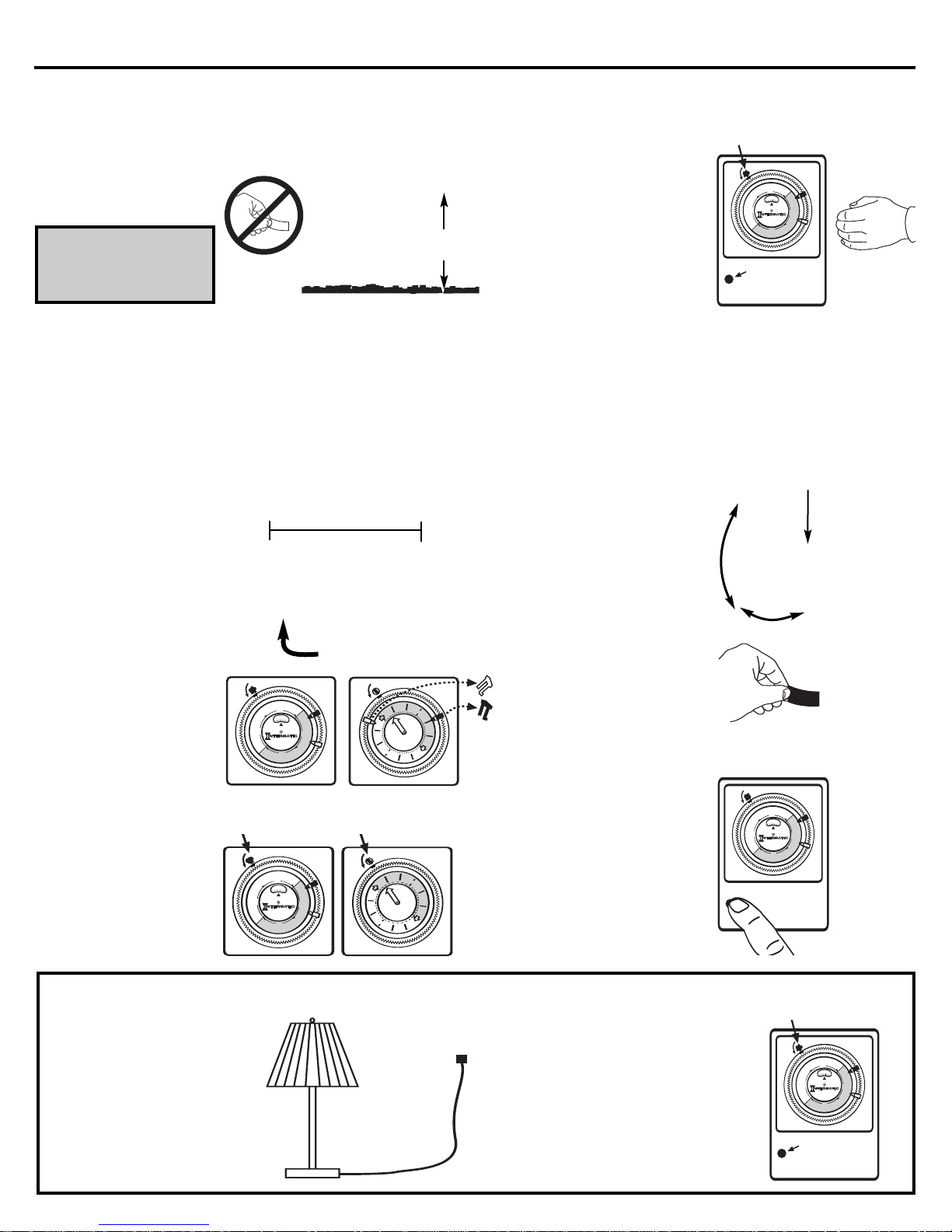
When used in conjunction with Intermatic Inc. Low Voltage Lights:
Hang timer/receiver and
1
plug into a GFCI outdoor
electrical outlet that has
a weather resistant cover.
Do not remove the label
covering the photocell.
IMPORTANT: See warning
information located on the
label inside the cover lid
of the timer/receiver.
Install 4 AA batteries into
the transmitter unit. The
2
transmitter unit will take
approximately one minute
to become active.
Plug the Intermatic Inc.
3
power pack into the
timer/receiver.
The timer/receiver will
now be used for the
timer operation.
Remove back plate screws
to access battery compartment.
Batteries not included.
Locate sensor up to 40 ft.
away from timer/receiver.
Fig. 1
3 ft. minimum
(91.44 cm)
Turn off the timer/receiver.
6
Press and hold the setup/test
mode button (located to the
lower left of the timer dial) for
two seconds.The receiver is
now in “setup” mode. The
photocell must be covered.
Test by moving your hand in
front of the transmitter. The
lights will be switched on for
15 seconds.
In normal operation the
lights will be turned on
for 5 minutes.
You should now be able
7
to mount the transmitter up
to 40 feet from the timer/
receiver depending on
conditions.
Place the transmitter in the
approximate location desired.
Move your hand in front of
the transmitter and verify that
it is turning the lights on.
Using the screws provided,
mount the transmitter and
aim it towards the area you
want to protect.
Turn timer/receiver switch clockwise
one more “click’
Loosen the locking nut to aim sensor
as needed. Tighten nut to secure at
the desired angle.
Setup
to turn timer off.
Test Button
Position the trippers
4
on the timer/receiver
at the “ON” and “OFF”
times used for the
lighting power pack;
then, remove the
trippers from the
lighting power pack.
Receiver/timer control
Rotate switches clockwise to “ON” position.
urn the timer/receiver
T
and the lighting Timer to
5
the “ON” position. The
lights should now be on.
When using something other than Intermatic Inc. Low Voltage Lights:
Outdoors: Hang timer/receiver
and plug into a GFCI outdoor
1a
electrical outlet that has a
weather resistant cover.
(see fig.1 above)
Indoors: Hang timer/receiver
and plug into a grounded, indoor
1b
electrical outlet.
Plug the light or other product
2
into the timer/receiver.
Remove trippers from
power pack timer.
Lighting power pack timer control
Test the distance and
peripheral sensitivity of the
transmitter by standing out
of sight of the transmitter
and moving into range
while observing when the
lights turn on.
Adjust the transmitter to
cover the largest, or specific
area desired. Tighten the
locking bolt.
Press and hold the test/setup
8
button for two seconds to exit
the setup mode on the
timer/receiver. Remove the
label covering the photocell.
To test operation at any time,
press the test/setup button
9
and verify that the transmitter
and receiver are working.
Position the trippers on the
timer/receiver at the “ON” and
3
“OFF” times desired.
Turn the timer/receiver and the
light or other product to the “ON”
4
position.
The light, or product
should now be on.
Follow steps 6 thru 9 (above) to
5
complete the setup and testing.
Turn timer/receiver switch
clockwise one more “click”
to turn timer off.
Setup Test Button
Page 2
AL1200TK Instrucciones para la configuración del transmisor y el receptor.
ON/OFF
TIME OF DAY
7
6
5
4
HEAVY DUTY
A
M
1
2
•
1
1
•
1
0
•
9
•
8
•
7
•
6
•
5
•
4
•
3
•
2
•
1
•
1
2
•
1
1
•
1
0
•
9
•
8
•
7
•
6
•
5
•
4
•
3
•
2
•
1
•
A
M
P
M
P
M
ON/OF
F
TIME OF DA
Y
7
6
5
4
HEAVY DUTY
A
M
1
2
•
1
1
•
1
0
•
9
•
8
•
7
•
6
•
5
•
4
•
3
•
2
•
1
•
1
2
•
1
1
•
1
0
•
9
•
8
•
7
•
6
•
5
•
4
•
3
•
2
•
1
•
A
M
P
M
P
M
ON/OFF
TIMETIME
2
2
4
4
6
6
8
8
10
10
12
1
2
!
!
ON/OFF
TIME OF DAY
7
6
5
4
HEA
VY DUTY
A
M
1
2
•
1
1
•
1
0
•
9
•
8
•
7
•
6
•
5
•
4
•
3
•
2
•
1
•
1
2
•
1
1
•
1
0
•
9
•
8
•
7
•
6
•
5
•
4
•
3
•
2
•
1
•
A
M
P
M
P
M
ON/OFF
TIME OF DAY
7
6
5
4
HEAVY DUTY
A
M
1
2
•
1
1
•
1
0
•
9
•
8
•
7
•
6
•
5
•
4
•
3
•
2
•
1
•
1
2
•
1
1
•
1
0
•
9
•
8
•
7
•
6
•
5
•
4
•
3
•
2
•
1
•
A
M
P
M
P
M
ON/OFF
TIMETIME
2
2
4
4
6
6
8
8
1
0
1
0
1
2
1
2
AM
P
M
ON/OFF
TIME OF DAY
7
6
5
4
HEAVY DUTY
A
M
1
2
•
1
1
•
1
0
•
9
•
8
•
7
•
6
•
5
•
4
•
3
•
2
•
1
•
1
2
•
1
1
•
1
0
•
9
•
8
•
7
•
6
•
5
•
4
•
3
•
2
•
1
•
A
M
P
M
P
M
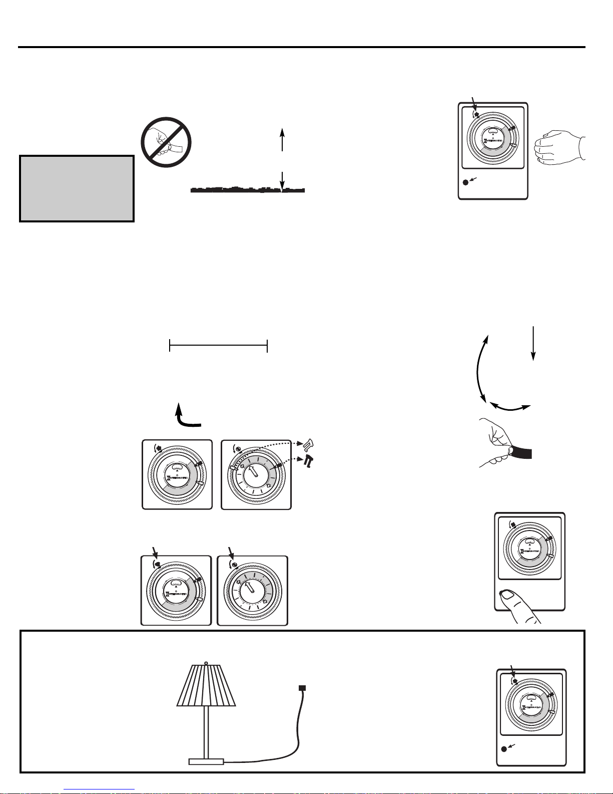
Cuando se utilicen con lámparas de bajo voltaje de Intermatic Inc.:
Cuelgue el temporizador/
1
receptor y conéctelo a una
toma eléctrica externa
GFCI que tenga una
cubierta resistente a la
intemperie. No retire la etiqueta que cubre la fotocelda.
IMPORTANTE: Véase la
Fig. 1
3 pies mínimo
(91,44 cm)
Apague el temporizador/
6
receptor. Mantenga presionado
el botón de configuración/
prueba (ubicado en la parte
inferior izquierda de la esfera
del temporizador) durante dos
segundos. Ahora el receptor
está en el modo de
"configuración". Debe cubrir
la fotocelda.
información de advertencia
que contiene la etiqueta
ubicada en la parte interna
de la cubierta del
temporizador/receptor.
Retire los tornillos de la placa posterior para
obtener acceso al compartimiento de la batería.
Realice la prueba moviendo
su mano frente al transmisor.
Las lámparas se encenderán
durante 15 segundos.
En condiciones de operación
Instale 4 baterías AA en
2
la unidad de transmisión.
El transmisor tardará
aproximadamente un
minuto en activarse.
normales, las lámparas permanecerán
encendidas 5 minutos.
Ahora debería poder instalar el
7
transmisor con una separación
máxima de 40 pies con respecto
al temporizador/receptor,
dependiendo de las condiciones.
Coloque el transmisor en la ubicación
aproximada que desee. Mueva su
mano frente al transmisor y verifique
que éste enciende las lámparas.
Utilice los tornillos suministrados para
instalar el transmisor y oriéntelo hacia
el área que desea proteger.
Para probar el alcance y la
sensibilidad del transmisor con
respecto a los objetos periféricos,
colóquese fuera del alcance del
transmisor, camine hacia él y observe
cuándo encienden las lámparas.
Conecte el transformador
3
de Intermatic Inc. al
temporizador/receptor.
El temporizador/
receptor se
utilizará ahora
para la
operación del
temporizador.
Establezca las
4
flechas indicadoras
del temporizador/receptor
en las horas de
No se incluyen las baterías
La separación entre el sensor y temporizador/receptor
no debe ser mayor de 40 pies.
Retire las flechas indicadoras del temporizador
del transformador.
"ENCENDIDO" y "
APAGADO" utilizadas
para el transformador de
iluminación; luego, retire
las flechas indicadoras
del transformador de
iluminación.
Coloque el temporizador/
5
receptor y el temporizador
de iluminación en la
posición "ON" (encendido). Ahora las lámparas
deben estar encendidas.
Control del receptor/
temporizador
Gire los interruptores en el sentido de las agujas del
reloj hasta la posición "ON" (encendido).
Control del temporizador del
transformador de iluminación
Ajuste el transmisor para cubrir la
mayor superficie o el área específica
que desee. Apriete el perno de fijación.
Mantenga presionado el botón de
8
prueba/configuración durante dos
segundos para salir del modo de
configuración del temporizador/
receptor. Retire la etiqueta que cubre
la fotocelda.
Para probar la operación en cualquier
9
momento, presione el botón de
prueba/configuración y verifique que
el transmisor y el receptor estén
funcionando.
Cuando se utilicen productos que no sean lámparas de bajo voltaje de Intermatic Inc.:
Para exteriores: Cuelgue el temporizador/
1a
receptor y conéctelo a una toma
eléctrica externa GFCI que tenga una
cubierta resistente a la intemperie.
(véase la figura 1 arriba)
Para interiores: Cuelgue el temporizador/
1b
receptor y conéctelo a una toma eléctrica
interna con conexión a tierra.
Conecte la lámpara u otro producto
2
al temporizador/receptor.
Establezca las flechas indicadoras del
3
temporizador/ receptor en las horas de
"ENCENDIDO" y "APAGADO" deseadas.
Coloque el temporizador/receptor
4
y la lámpara u otro producto en la posición "ON" (encendido). La lámpara o el
producto debe estar encendido ahora.
Siga los pasos del 6 al 9 (arriba) para
5
completar el proceso de configuración
y prueba.
Para apagar el temporizador, gire el interruptor del
temporizador/receptor en el sentido de las
agujas del reloj hasta escuchar otro "clic".
Botón de
configuración/
prueba
Afloje la contratuerca para orientar el
sensor según sea necesario. Ajuste la
tuerca para asegurar el sensor en el
ángulo deseado.
Para apagar el temporizador, gire
el interruptor del temporizador/
receptor en el sentido de las agujas
del reloj hasta escuchar otro "clic".
Botón de
configuración/
prueba
Page 3

ON/OFF
TIME OF DAY
7
6
5
4
HEAVY DUTY
A
M
1
2
•
1
1
•
1
0
•
9
•
8
•
7
•
6
•
5
•
4
•
3
•
2
•
1
•
1
2
•
1
1
•
1
0
•
9
•
8
•
7
•
6
•
5
•
4
•
3
•
2
•
1
•
A
M
P
M
P
M
AL1200TK Consignes d'installation du transmetteur et du récepteur.
ON/OFF
TIME OF DAY
7
6
5
4
HEAVY DUTY
A
M
1
2
•
1
1
•
1
0
•
9
•
8
•
7
•
6
•
5
•
4
•
3
•
2
•
1
•
1
2
•
1
1
•
1
0
•
9
•
8
•
7
•
6
•
5
•
4
•
3
•
2
•
1
•
A
M
P
M
P
M
ON/OFF
TIME OF DA
Y
7
6
5
4
HEAVY DUTY
A
M
1
2
•
1
1
•
1
0
•
9
•
8
•
7
•
6
•
5
•
4
•
3
•
2
•
1
•
1
2
•
1
1
•
1
0
•
9
•
8
•
7
•
6
•
5
•
4
•
3
•
2
•
1
•
A
M
P
M
P
M
ON/OFF
TIMETIME
2
2
4
4
6
6
8
8
10
10
12
1
2
!
!
ON/OFF
TIME OF DAY
7
6
5
4
HEAVY DUTY
A
M
1
2
•
1
1
•
1
0
•
9
•
8
•
7
•
6
•
5
•
4
•
3
•
2
•
1
•
1
2
•
1
1
•
1
0
•
9
•
8
•
7
•
6
•
5
•
4
•
3
•
2
•
1
•
A
M
P
M
P
M
ON/OF
F
TIME OF DA
Y
7
6
5
4
HEAVY DUTY
A
M
1
2
•
1
1
•
1
0
•
9
•
8
•
7
•
6
•
5
•
4
•
3
•
2
•
1
•
1
2
•
1
1
•
1
0
•
9
•
8
•
7
•
6
•
5
•
4
•
3
•
2
•
1
•
A
M
P
M
P
M
ON/OFF
TIMETIME
2
2
4
4
6
6
8
8
1
0
1
0
1
2
1
2
AM
P
M
Lors d'un emploi en conjugaison avec les lampes basse tension d'Intermatic inc. :
Pendez le minuteur-
1
récepteur et branchez-le
dans une prise électrique
extérieure à protection de
défaut à la terre munie
d'un couvercle résistant
aux intempéries. Ne
retirez pas l'étiquette
recouvrant la photocellule.
IMPORTANT : voyez
l'avertissement situé sur
l'étiquette dans le couvercle
du minuteur-récepteur.
Fig. 1
Retirez les vis de la plaque arrière pour
accéder au compartiment d'alimentation.
3 pi minimum
(91,44 cm)
Éteignez le minuteur-récepteur.
Tenez le bouton du mode
6
d'installation / d'essai (à la
gauche inférieure du cadran
de minuterie) enfoncé pendant
deux secondes. Le récepteur
se trouve maintenant en mode
« installation ». La photocellule
doit être couverte.
Testez en bougeant votre main
devant le transmetteur.
Les lampes s'allumeront
15 secondes.
En fonctionnement normal, les
lampes s'allumeront 5 minutes.
Tournez le commutateur du minuteur-récepteur dans
le sens des aiguilles d'une montre d'un « cran »
supplémentaire pour éteindre la minuterie.
Bouton d'essai
d'installation
Installez 4 piles AA dans
2
l'unité de transmetteur.
L'unité de transmetteur
prendra environ une
minute à s'activer.
Enfichez le bloc d'alimen-
3
tation Intermatic inc. dans
le minuteurrécepteur.
Le minuteurrécepteur
servira
maintenant
à l'application
de minuterie.
Réglez les déclencheurs
4
sur le minuteur-récepteur
aux temps de marche et
d'arrêt utilisés pour le bloc
d'alimentation d'éclairage;
enlevez ensuite les
déclencheurs du bloc
d'alimentation d'éclairage.
Mettez le minuteur-
5
récepteur et la minuterie
d'éclairage en position
« MARCHE ».
Les luminaires devraient
maintenant être allumés.
Piles non incluses.
Placez le détecteur à 40 pi au
plus du minuteur-récepteur.
Enlevez les déclencheurs
de la minuterie du bloc
d'alimentation.
Commande du
récepteur-minuteur
Faites tourner les commutateurs dans le sens des
aiguilles d'une montre jusqu'en position « MARCHE ».
Commande de la minuterie du
bloc d'alimentation d'éclairage.
Vous devriez maintenant être
7
capable de monter le
transmetteur jusqu'à 40 pieds
du minuteur-récepteur selon
les conditions.
Placez le transmetteur à
l'endroit approximatif désiré.
Bougez votre main devant le
transmetteur, et vérifiez qu'il
allume les lampes.
À l'aide des vis fournies,
montez le transmetteur, et
pointez-le vers la zone
que vous voulez protéger.
Testez la distance et la
sensibilité périphérique du
transmetteur en vous tenant
hors champ, puis en vous
déplaçant à portée tout en
observant à quel moment les
lampes s'allument.
Ajustez le transmetteur pour
inclure la zone la plus large ou
l'aire particulière désirée.
Serrez le boulon de blocage.
Tenez le bouton d'installation /
d'essai enfoncé pendant deux
8
secondes pour sortir du mode
d'installation sur le minuteurrécepteur. Retirez l'étiquette
recouvrant la photocellule.
Pour contrôler l'état de marche
9
en tout temps, appuyez sur le
bouton d'essai / d'installation,
et vérifiez si le transmetteur et
le récepteur fonctionnent.
Desserrez l'écrou de blocage pour pointer le
détecteur où il faut. Serrez l'écrou pour fixer
à l'angle désiré.
Lors d'un emploi avec un autre dispositif que les lampes basse tension d'Intermatic inc. :
À l'extérieur : pendez le minuteur-
1a
récepteur
prise de courant extérieure à
protection de défaut à la terre munie
d'un couvercle résistant aux
intempéries. (V
À l'intérieur : pendez le minuteur-
1b
récepteur
de courant intérieure mise à la terre.
Enfichez la lampe ou l'autre produit
2
dans le minuteur-récepteur
, et branchez-le dans une
oir la fig.1 ci-dessus.)
, et branchez-le dans une prise
.
Réglez les déclencheurs sur
3
le minuteur-récepteur aux
temps de marche et d'arrêt désirés.
Mettez le minuteur-récepteur et la
lampe ou l'autre produit en position
4
« MARCHE ». Le luminaire ou le
produit devrait maintenant être allumé.
Suivez les étapes 6 à 9 (ci-dessus)
5
pour terminer l'installation et l'essai.
ournez le commutateur du minuteur-
T
récepteur dans le sens des aiguilles d'une
montre d'un « cran » supplémentaire
pour éteindre la minuterie.
Bouton d'essai
d'installation
Page 4

The wiring is to be protected by routing in close proximity to the luminaire or fitting, or next to a building structure such as a house or deck.
The wiring shall not be buried except for a maximum 3 inches (7.6 cm) in order to connect to the main secondary wire.
The luminaires shall not be installed within 10 feet (1.52m) of a pool, spa, or fountain.
Los cables deben protegerse instalándolos muy cerca de las luminarias o accesorio, o junto a una estructura de un edificio tal como una
casa o una terraza.
Los cables no deben enterrarse excepto un máximo de 7,6 cm (3 pulgadas) para conectar al cable principal secundario.
Las luminarias no deben instalarse a menos de 3 m (10 pies) de una alberca, balneario o fuente.
La protection du câblage doit être ef
telle qu’une maison ou une terrasse.
Le câblage ne doit pas être souterrain sauf pour les 7,6 cm (3 po) maximum servant à la connexion au câblage secondaire principal.
Les lumières ne doivent être installées qu’à 3 m (10 pi) d’une piscine, d’un spa ou d’une fontaine.
If within one (1) year from the date of purchase, this product fails due to a defect in material or workmanship, Intermatic Incorporated will repair or replace
it, at its sole option, free of charge. This warranty is extended to the original household purchaser only and is not transferable. This warranty does not apply
to: (a) damage to units caused by accident, dropping or abuse in handling, acts of God or any negligent use; (b) units which have been subject to unauthorized repair, opened, taken apart or otherwise modified; (c) units not used in accordance with instructions; (d) damages exceeding the cost of the product;
(e) sealed lamps and/or lamp bulbs, LED’s an batteries; (f) the finish on any portion of the product, such as surface and/or weathering, as this is considered
normal wear and tear; (g) transit damage, initial installation costs, removal costs, or reinstallation costs.
INTERMATIC INCORPORATED WILL NOT BE LIABLE FOR INCIDENTAL OR CONSEQUENTIAL DAMAGES. SOME STATES DO NOT ALLOW THE EXCLUSION
OR LIMITATION OF INCIDENTAL OR CONSEQUENTIAL DAMAGES, SO THE ABOVE LIMITATION OR EXCLUSION MAY NOT APPLY TO YOU. THIS WARRANTY IS IN LIEU OF ALL OTHER EXPRESS OR IMPLIED W
THE WARRANTY OF FITNESS FOR A PARTICULAR PURPOSE, ARE HEREBY MODIFIED TO EXIST ONLY AS CONTAINED IN THIS LIMITED WARRANTY, AND
SHALL BE OF THE SAME DURATION AS THE WARRANTY PERIOD STATED ABOVE. SOME STATES DO NOT ALLOW LIMITATIONS ON THE DURATION OF AN
IMPLIED W
This warranty gives you specific legal rights and you may also have other rights which vary from state to state. Warranty service is available by mailing postage
prepaid to: Intermatic Incorporated/After Sales Service/7777Winn Rd., Spring Grove, IL 60081-9698/815-675-7000 http://www.intermatic.com Please be
sure to wrap the product securely to avoid shipping damage.
Si en un plazo de uno (1) año contados a partir de la fecha de compra, el producto falla debido a un defecto de material o mano de obra, Intermatic
Incorporated lo reparará o reemplazará, a opción propia, de forma gratuita. Esta garantía se aplica solamente al comprador particular original y no es transferible. Esta garantía no se aplica en los casos siguientes: (a) daños en unidades causados por accidente, caídas o abuso durante su manipulación, fuerza
mayor o cualquier uso negligente; (b) unidades que hayan sido sometidas a una reparación no autorizada, abiertas, desmontadas o modificadas de otra forma;
(c) unidades que no se hayan usado según las instrucciones; (d) daños que excedan el costo del producto; (e) lámparas selladas y bombillas, LED y pilas; (f)
el acabado de cualquier parte del producto, tal como la superficie y el desgaste debido a la intemperie, ya que esto se considera como un desgaste natural;
(g) daños durante el transporte, costos de instalación iniciales, costos de desmontaje o costos de reinstalación.
INTERMATIC INCORPORATED NO SERÁ RESPONSIBLE DE LOS DAÑOS EMERGENTES O CONCOMINATES. ALGUNOS ESTADOS NO PERMITEN LA
EXCLUSIÓN O LIMITACIÓN DE LOS DAÑOS EMERGENTES O CONCOMITANTES, POR LO QUE ES POSIBLE QUE NO SE APLIQUE EN SU CASO LA
LIMITACIÓN O EXCLUSIÓN ANTERIOR. ESTA GARANTÍA ES EN LUGAR DE LAS DEMÁS GARANTÍAS EXPLÍCITAS O IMPLÍCITAS. TODAS LAS GARANTÍAS
IMPLÍCITAS, INCLUIDA LA GARANTÍA DE COMERCIABILIDAD Y LA GARANTÍA DE IDONEIDAD PARA CIERTO FIN, SE MODIFICAN AQUÍ PARA EXISTIR
SÓLO SEGÚN ESTÁN CONTENIDAS EN ESTA GARANTÍA LIMITADA, Y DEBEN TENER LA MISMA DURACIÓN QUE EL PERÍODO DE GARANTÍA INDICADO
ARRIBA. ALGUNOS ESTADOS NO PERMITEN LIMITACIONES DE LA DURACIÓN DE UNA GARANTÍA IMPLÍCITA, POR LO QUE ES POSIBLE QUE LA
LIMITACIÓN ANTERIOR NO SE APLIQUE EN SU CASO.
Esta garantía le da unos derechos específicos y es posible que también tenga otros derechos, que pueden variar de un estado a otro. El servicio de la garantía está disponible enviando el pr
Spring Grove, IL 60081-9698/815-675-7000 http://www.intermatic.com Asegúrese de envolver bien el producto para evitar daños durante el transporte.
Si dans un délai de un (1) an à compter de la date d'achat, ce produit s'avère défectueux pour vice de matériau ou de fabrication, Intermatic Incorporated le réparera ou le remplacera, la décision appartenant Intermatic Incorporated, sans frais. Cette garantie ne concerne que l'acheteur initial et n'est pas transférable.
Cette garantie ne couvre pas : (a) dommages occasionnés par accident, chute ou abus lors de manipulations, cas fortuits ou toute négligence ; (b) unités ayant subi à
des réparations non autorisées, ouver
tions ; (d) dommages supérieurs au coût du produit ; (e) éclairage scellé et/ou ampoule, DEL et batteries ; (f) la finition d'une partie du produit, telle que les
rayures de surface et/ou le vieillissement climatique qui sont considérés comme une usure normale ; (g) dommages ayant lieu pendant le transport, frais
initiaux d'installation, de désinstallation ou de réinstallation.
INTERMATIC INCORPORATED N'ENDOSSE AUCUNE RESPONSABILITÉ QUANT AUX DOMMAGES ACCESSOIRES OU INDIRECTS. CERTAINES PROVINCES NE PERMETTENT P
VOUS CONCERNER. CETTE GARANTIECI-PRÉSENTES REMPLACE TOUTES AUTRES GARANTIES EXPRESSES OU TACITES. TOUTES LES GARANTIES
TACITES Y COMPRIS LA GARANTIE DE COMMERCIALISATION ET CELLE D'ADAPTABILITÉ À DES FINS PARTICULIÈRES SONT MODIFIÉES CI-PRÉSENTES
POUR N'EXISTER QUE TELLES QUELLES DANS CETTE GARANTIE LIMITÉE ET AURONT LA MÊME DURÉE DE V
INDIQUÉE CI-DESSUS. CER
INDIQUÉE CI-DESSUS PEUT NE PAS VOUS CONCERNER.
Cette garantie vous confère des droits légaux spécifiques mais vous pouvez en outre bénéficier de droits supplémentaires qui varient d'une province à l'autre
ou d'un état à l'autre. Le service sous garantie est disponible en envoyant le produit port prépayé à l'adresse suivante : Intermatic Incorporated/After Sales
Ser
dommage pendant l'expédition.
ARRANTY, SO THE ABOVE LIMITATION MAY NOT APPLY TO YOU.
AS D'EXCLUSIONS OU DE LIMITATIONS AUX DOMMAGES ACCESSOIRES OU CONSÉCUTIFS, LA LIMITE INDIQUÉE CI-DESSUS PEUT NE PAS
TAINES PROVINCES NE PERMETTENT PAS DE LIMITATIONS AUX TERMES DE LA DURÉE DE LA GARANTIE TACITE, LA LIMITE
vice/7777 W
inn Rd., Spring Gr
fectuée en acheminant les fils près des lumières, de raccords ou près de la structure d’un bâtiment
LIMITED ONE YEAR WARRANTY
ARRANTIES. ALL IMPLIED WARRANTIES, INCLUDING THE WARRANTY OF MERCHANTABILITY AND
GARANTÍA LIMITADA DE UN AÑO
oducto por correo con franqueo pagado con anterioridad a: Intermatic Incorporated/ After Sales Service/7777/Winn Rd.,
GARANTIE D’UNE ANNÉE
tes, démontées ou modifiées d'une quelconque façon ; (c) unités qui ne sont pas utilisées conformément aux instruc-
ALIDITÉ QUE LA PÉRIODE DE GARANTIE
ove, IL 60081-9698/815-675-7000 http://www
.intermatic.com Veiller à bien emballer le produit afin qu'il ne subisse aucun
INTERMATIC INCORPORATED
SPRING GROVE, ILLINOIS 60081-9698
158AL11200
 Loading...