

Page 1
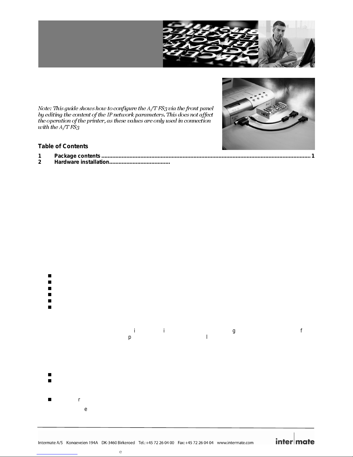
A/T FS3
Quick Installation Guide
– edition 2
This guide cover s the installation and basic configur ation of the Intermate
A/T FS3 internal interface. More detailed inf ormati on and procedures can
be found in the Intermat e A/T FS3 Coax/T winax Connection User’s Guide,
document no. GK-007-x .
Note: This guide shows how to configure the A/T FS3 via the front panel
by editing the content of the IP network parameters. This does not affect
the operation of the printer, as these values are only used in connection
with the A/T FS3
.
Table of Contents
1 Package contents ......................................................................................................................................1
2 Hardware installation.................................................................................................................................1
3 Printing a “Status Sheet”...................................................................................................... .................... 2
4 About configuration tools.........................................................................................................................2
4.1 The rotary switch.........................................................................................................................................2
4.2 Remote Menu System using a termi nal pr ogram..........................................................................................3
4.3 Front panel..................................................................................................................................................3
5 Initial Configuration for Coax or Twinax...................................................................................................5
5.4 Initial Coax configuration..............................................................................................................................5
5.5 Initial Twinax con figu r a tion...........................................................................................................................5
6 Ordering the IPDS Software Key for IPDS production printing............................................................... 6
7 Firmware upgrade......................................................................................................................................7
8 Documentation and software....................................................................................................................7
9 Customer Support ..................................................................................................................................... 7
10 Supported Printers.................................................................................................................................... 8
11 Importa nt inf or m a t i on about IPDS pr inting with the A/T FS3.................................................................. 8
12 Notices ....................................................................................................................................................... 8
1 Package contents
A/T FS3 Card
Coax DB9 connector cable
Twinax DB9 connector c able
Serial configur ation and upgrade cable
Getting Start ed (this brochure)
Documentati on and Utilities CD
2 Hardware installation
Important! Discharge yourself from static el ec tricity immediately befor e unpacking or otherwise handling interfaces
or memory. Do this by touchi ng an unpainted part of the printer’s metal c abinet. Alternatively, you can wear an antistatic wrist strap
1. If the printer is going to be used for IPDS printing and needs extra printer memory, you must install this ext r a
memory before installing the A/T FS3 in the printer.
2. Make sure you have the following items needed for the install ation:
the A/T FS3 interface
a Coax DB9 connector cable or a Twinax CB 9 connnector cable
(Note: If you are using an IBM cabl ing system, you need a Twinax dummy plug, which is av ailable from your
point of purchase or from Int ermate A/S.)
a screw driver
3. Power the printer Off and unplug the power cord. If the printer is not powered Off before the installation, parts
of the A/T FS3 or the printer may be perm anently damaged.
Page 2

gs-019-02 A/T FS3 Getting Started. Edition 2. 9 November 2004 page 2 of 8
4. Remove the metal plat e covering the option port by taking out the screws. Ref er to your printer documentation.
5. Remove any interfac e or cable occupying the printer’s internal port. Be sure to check that this is OK with the
network administr ator.
6. Unpack the A/T FS3 and slide it i nto t he internal port. Reattach the metal plate and secure the screws.
This concludes the phy si c al installation.
The next step is to connect the pri nter to the system and to perform the logical i nstallation, also called “initi al
configurati on” .
There are three configuration tools available. They are described in section 4, on page 2. You can, of c our se, just
skip to Initial Configuration for your chosen mode and refer back as necessary:
if the A/T FS3 is to be used in Coax mode, go to section 5.4, page 5.
if the A/T FS3 is to be used in Twinax mode, go to section 5.5, page 5.
3 Printing a “Status Sheet”
The A/T FS3 status sheet contains various information f or qui ck reference Before starting any kind of
configurati on, you may want to print a status sheet to see the current settings. You might also want to do this after
finishing a confi gur ation.
Press the “Status” butt on on the printer and a set of sheets will be printed. The first sheet is the print er status sheet,
which is followed by the A/T FS 3 status sheets. The information on the A/T FS 3 sheet i ncl udes the serial number,
some common option setti ngs and the firmware levels.
4 About configuration tools
Three tools are prov ided:
Rotary switch on the back of panel of the A/T FS3. This is important to know about even if you do not
actually use it t o make configurations with; theref ore this is the first topic below.
Remote configuration menu, using a terminal program. Through t he m enu, you c an do all of t he
configurati ons that are possible through the front panel or rotary switch – and much, much more.
Front pane l (not all printers have a front panel).
This Getting St arted Guide emphasizes the use of the front panel and rotary switch for initial configur ation because
some users find these methods to be the quickest when they just want to get thei r setup worki ng, test connectivity,
and so on.
4.1 The rotary switch
The rotary switch is on the bac k plate of the A/T FS3, so it is always accessible. Use a small scr ewdriver to move
the arrow around the 16 fixed items on the circle – labeled 0 to E.
0 is normal operation. The A/T FS3 is deliv ered with the rotary switch set i n position 0.
4 is Serial Administration Mode (used for downloads); section 7, on page 7, shows how this is used.
Note: The User’s Guide refers to rotary switch position 4 as “not used”; starting with boot code
K60_2071, this is no longer true. Please see the “errata sheet” to the Guide (on the CD and on the product
support portal). If your boot code is older than K60_2071, you should upgrade (see section 7, page 7)!
5 is Terminal Configurati on M ode; section 4.2, on page 3, shows how this is used.
All of the other items allow you to either configure parameters or pri nt c onfiguration dumps and so on. A
complete overview is in the User’s Guide, Chapter 4, section 4.2, and Appendix E.
Configuration v ia the switch on the A/T FS3 provides access to some impor tant options. Each time the menu
system is accessed or a change is made, a page is printed, telling you what you can do next. The page includes a
switch summary, whi c h is usef ul when referencing the availabl e options.
Each time you want to configure something using the rotary switch, you should follow this procedure:
1. Power Off the printer (not necessary with Coax).
2. The Switch Menu System as such runs f r om “6" t o “D”. “D” i s the Printer Emulation. Select the desired posi tion.
3. Power On the printer and wait for a page to be printed.
4. Follow the instruc tions on the page to make a change – or decide not to change anythi ng (i n this case, go
directly to the finishing step).
Page 3

gs-019-02 A/T FS3 Getting Started. Edition 2. 9 November 2004 page 3 of 8
5. When you are finished, power the printer Off and set the switch to position “0" (= Normal operation). Changed
settings, if any, will be activated on the next power On.
4.2 Remote Menu System using a terminal program
The Menu System included in theA/T FS3 can be accessed remotely via a terminal pr ogr am . T he following
instructions apply to the HyperTerminal
TM
program delivered with Windows. T hey c an be used with alm ost any
terminal progr am with only a few adjustments if any.
1. Power the printer Off.
2. Remove the Coax or Twinax DB9 connec tor cable, so the printer is not connect ed to any network.
3. Connect the PC to the printer via the serial config/upgrade cable included with the A/T FS3.
4. Start the termi nal pr ogram.
5. Turn the rotary switch on the A/T FS3 to position “5” to activate the Remote Menu System .
6. Power the printer On. The Menu System pr esents i tself with the main menu from where you can access and
edit all options.
7. When you are finished edit ing the options, return to the main menu.
8. Exit the Remote Menu System by turning the rotary switch to position “ 0”.
9. Power the printer Off.
10. Reconnect the printer to the system.
11. The new settings are activated the next tim e the pri nter is powered On.
The User’s Guide provi des more information on using HyperTerminal.
4.3 Front panel
When you configure using the front panel, you edit the parameters labeled IP-address and Subnet m ask address.
This does not affect t he oper ation of the printer, as these settings are onl y used by t he A/T FS3.
Most front panel s are operated like this:
1. Make sure that the rotary swit c h is set to posi tion “0.” If it is not, power the print er Off , and set it to 0.
2. Power the printer On and Pr ess the “M ode” button.
3. Scroll through the choices with “+” or “-“ until you see Interface or Interface type. Press Enter.
4. If the panel doesn’t al r eady show interface type as “Option”, scroll through the choices with “+” or “-“ until it
does. Press Enter.
5. Push the “>” button; you will be in the “TCP/IP” part of the menu.
6. Push the “>” button again. Now you can use “+” or “-“ to scroll through “DHCP”, “IP Address”, “Subnet Mask”
and “Gateway”. Let us assume you want t o work wit h the I P A ddr ess parameter.
7. When you have scrolled t o “IP Address”, pr es s “Enter” to activate editi ng.
8. Editing start s on the ri ght-most digit. Use the “+” and “-” buttons to adjust the value to your liking.
9. If you need to edit other di gits, use the “<” and “>” buttons to move to the desired di git(s). Each value is set with
the “+” and “-” buttons.
10. To finish editing, press the “Enter” butt on; this will also save the value.
11. If you need to work with a different parameter, use the “+” or “-“ buttons to toggle through, for example to
“Subnet Mask”.
12. When you are done with the last “Enter” (to save a setting) , press Exit/Mode.
13. You may need to power the printer Off – and then On – to activate a changed setting.
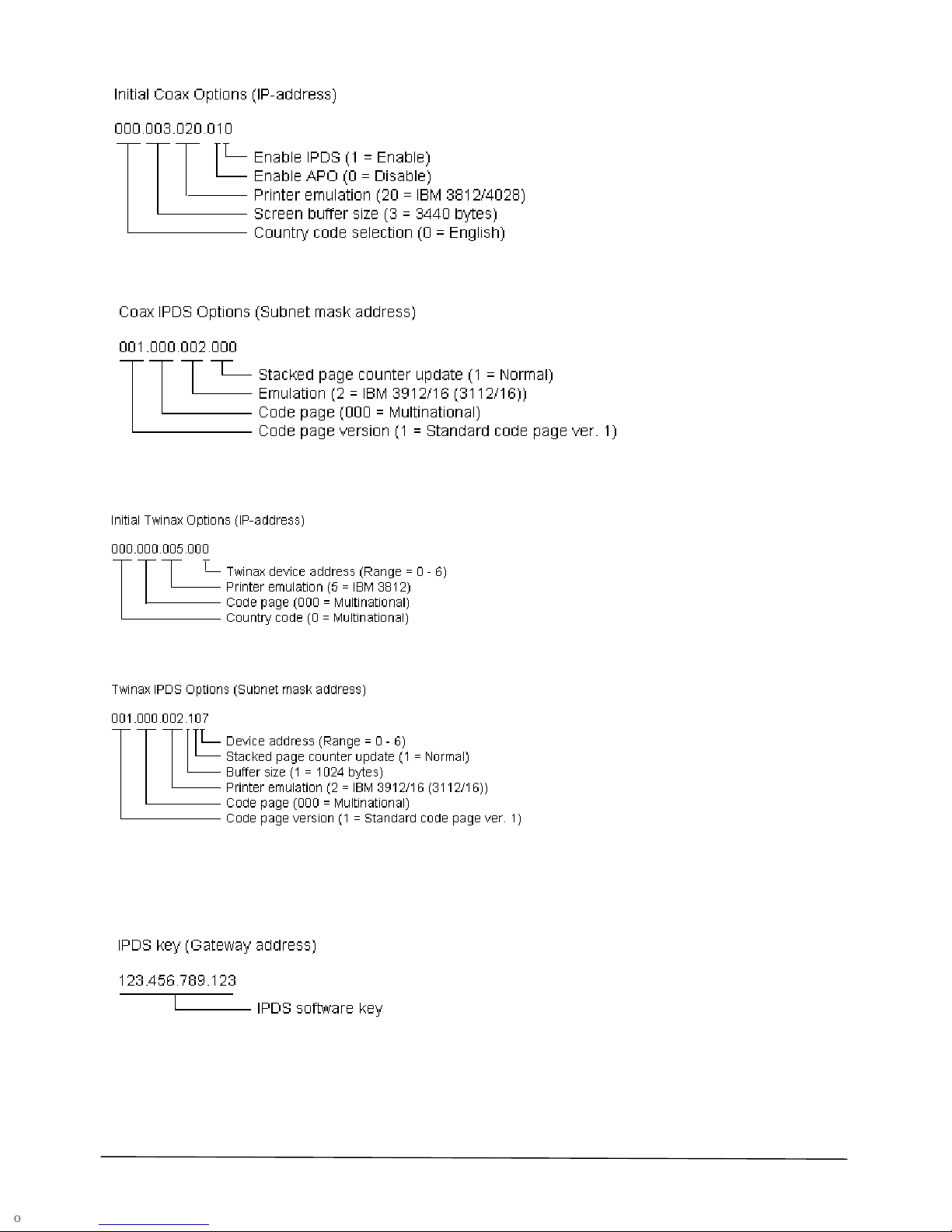
Depending on the mode the A/T FS3 is runni ng (Coax or Twinax), the address bytes control different options. See
Figure 1 - Figure 4 below.
Page 4
gs-019-02 A/T FS3 Getting Started. Edition 2. 9 November 2004 page 4 of 8
Figure 1 Initia l Coax Options
Figure 2 Coax IPDS Options
Figure 3 Initia l T winax Options
Figure 4 Twinax IPDS Options
You can also use the front panel to enter an IPDS key in the parameter labelled Gateway address. Navigation is
the same as described for the ot her two parameters.
Figure 5 IPDS Key
The User’s Guide contains a table with page references to all opti ons descri ptions, showing all valid option values;
refer to “The Front Panel” in chapter 4, section 4.1.
Page 5
gs-019-02 A/T FS3 Getting Started. Edition 2. 9 November 2004 page 5 of 8
5 Initial Configuration for Coax or Twinax
5.4 Initial Coax configuration
1. Insert the Coax cable’s DB9 connector in the A/T FS3 and connect the Coax connect or wit h the communication
cable from the IBM 3x74 cont r oller .
2. Power the printer On.
3. Create your host pri nter(s).
1. Create a definition for an IBM SCS printer in VTAM according to the Printer Em ulation selected in the A/T
FS3. The default is an IBM 3812 printer. Consult your system admi nistr ator if in doubt.
2. If you intend to print IP DS, then cr eate a VTAM definition for an IPDS printer default IPDS Emulation is an
IBM 3912/16 (3112/ 16) 300 dpi pri nter.
4. If you need to have other option settings than the factory defaults, y ou c an adjust the most important options
via the front panel ( see section 4.3, page 3) or via the rotary switch menu system (see section 4.1, page 2).
The options in question ar e P rinter Emulation, Screen Buffer Si z e, and Count ry Code Selection.
5. This concludes the S CS installation. You can check the opti ons settings by printing a status sheet (see secti on
3, page 2). If you wish to be able to print IPDS as well, continue with the next steps.
6. To enable IPDS printi ng v ia the f ront panel: IPDS printing is controll ed by the right-most digit of the IP-address
parameter. Assuming that all the other digits are left at def ault, you would be changing 000.003.020. 010
to
000.003.020.011
. See section 4. 3, page 3, for instructions on how to use the front panel.
Alternatively, you can enable IPDS printing via the rotary switch menu system (see section 4.1, page 2).
When IPDS printing is enabled it is in a demo mode. For production printing, you will need an IPDS
software key to enter IPDS production printing. See section 6, Ordering the IPDS Software Key for IPDS
production printing, page 6. The software key needed for IPDS production printing is entered via the
front panel. This is done on the front panel by editing the field used for Gateway address (as shown in
section 4.3, page 3); consult the User’s Guide for alternative approaches.
7. If you wish to have other IP DS opti on settings than the factory default s, you can adjust the most important
options via the fr ont panel (see section 4.3, page 3) or via the rotary switch menu system (see section 4.1,
page 2). The IPDS options i n question are Stacked Page Counter Update, Emulation, Code Page, and Code
Page Version.
This concludes the IPDS installation.
5.5 Initial T winax configuration
1. You must set a device address BEFORE you connect to your system controller . The default device address is
zero; valid val ues are [ 0-6]. Before selecting an address, print a list of device addresses on the current system
printer wit h the CL command on y our AS/ 400:
PRTDEVADR <Enter>
This prompts you for a device c ontroller description, i.e.:
CTL## <Enter> (“##” = controller number)
Contact your system administrator if in doubt.
The following instruc tions are for setting the device addr es s via the front panel. You can use the Switc h Menu
System instead (see secti on 4.1, page 2).
2. Using the buttons as explained in section 4.3, page 3, navigate to the IP Address parameter and start edi ting
by pressing Enter.
3. The twinax SCS devic e address is stored in the right-most digit. Assuming that 000.000.005.000
is default, and
your chosen twinax devic e number is 4, you would change the address to 000.000.005. 004
. If the device
number is 5, change the addr ess to 000.000.005.005
. And so on. If the device num ber is 0, l eav e the settings
unchanged. Valid values are from [0 – 6]. The device address is disabled if a v alue of 7 or more is entered.
4. If you need to have other option settings than the factory defaults, y ou c an adjust the most important options
via the front panel ( see the ov erview in section 4.3, page 3) or via the Switch Menu Sy stem ( see section 4.1,
page 2). The options in question are Printer Emulation, Code Page, and Count r y Code.
5. This concludes the S CS configuration. You can check the options settings by printing a status sheet (see
section 3, page 2). If you wish to be able to print IPDS as well, continue with the steps 6-8. Otherwise, proceed
to step 9, page 6.
6. To enable IPDS printi ng v ia the f ront panel: IPDS printing is controll ed by the right-most digit of the Subnet
Mask parameter, which r epr esent s the IPDS device address. On the front panel, edit the right-most digit. For
Page 6
gs-019-02 A/T FS3 Getting Started. Edition 2. 9 November 2004 page 6 of 8
example, if the chosen IPDS Dev ic e num ber is 3, assuming that all the other digits are left at def ault, you would
be changing 001.000.002.107
to 001.000.002.103 S ee secti on 4.3, page 3. Valid values for IPDS printing ar e
[0-6]; the default value 7 means that IPDS printing is disabled.
You can also enable IPDS printing via the Switch Menu System (see section 4.1, page 2).
When IPDS printing is enabled it is in a demo mode. For production printing, you will need an IPDS
software key to enter IPDS production printing. See section 6, Ordering the IPDS Software Key for IPDS
production printing, page 6. The software key needed for IPDS production printing is entered via the
front panel. This is done on the front panel by editing the field used for Gateway address (as shown in
section 4.3, page 3); consult the User’s Guide for alternative approaches.
7. If you wish to have other IP DS opti on settings than the factory default s, you can adjust the most important
options via the fr ont panel (see section 4.3, page 3) or via the Switch Menu System (see section 4.1, page 2).
The IPDS options in questi on ar e P ri nter Emulation, Stacked Page Counter Updat e, Buffer Size, Code Page,
and Code Page Version.
8. Power the printer Off.
9. If you already have an AS/ 400 pri nter device description av ailable on the system, you can complete the
install ation now by connecting the printer to the system and powering it On. Otherwise, you should NOT
connect it, but keep the printer powered off and continue with the steps below.
The steps below apply to the c onfiguration of an AS/400 when attaching a pr inter with the A/T FS3.
10. Enable Auto Configuration, if necessary, with the CL command:
CHGSYSVAL SYSVAL(QAUTOCFG) VALUE('1') <Enter>
11. Connect the printer to the system and power it On.
12. Verify the detection of a new device type *3812 and optionally *IPDS, by using the CL command WRKDE V D
PRT* and pressing F5 (ref resh) continuously.
13. If you want to enable OS/400 AFP Print Services for the *IPDS dev ic e use the following commands (sample
device name PRT08):
VRYCFG CFGOBJ(PRT08) CFGTYPE(*DEV) STATUS(*OFF) <Enter>
CHGDEVPRT DEVD(PRT08) AFP(*YES) <Enter>
VRYCFG CFGOBJ(PRT08) CFGTYPE(*DEV) STATUS(*ON) <Enter>
14. Start the Printer Writer for the device:
STRPRTWTR DEV(PRT08) <Enter>
15. Make a test printout:
CHGJOB PRTDEV(PRT08) <Enter>
PRTUSRPRF <Enter>
If you do not receive a printout, check if there is a message waiting on the wri ter:
WRKWTR PRT* <Enter>
16. If you had to enable Auto Configuration in step 10, disabl e it again:
CHGSYSVAL SYSVAL(QAUTOCFG) VALUE('0') <Enter>
This completes the installation.
6 Ordering the IPDS Software Key for IPDS production printing
In order to use the A/T FS3 for IPDS produc tion printing you need a software key.
The key is ordered from your point of purchase. If you bought the A/T FS3 directl y f r om Intermate A/S, you can
order the key by fax or e-mail ([email protected]). In both cases you m ust pr ov ide the following minimum
information.
The 7 digit serial number ( S/ N) found on the A/T FS3 status sheets.
Kyocera Printer type (model number).
Your name, company and information on how to reach you.
Page 7

gs-019-02 A/T FS3 Getting Started. Edition 2. 9 November 2004 page 7 of 8
7 Firmware upgrade
Before starting to use your A/T FS3, you should check the current firmware level on a status sheet (see how on
page 2). Visit www.intermate.com/atfs3
to see if there is newer firmware. If so, you shoul d update the A/T FS3.
The components used in the A/T FS3 are:
K60-xxxx.zip Boot code
K61-xxxx.zip Coax main code
K62-xxxx.zip Twinax main code
K63-xxxx.zip IPDS firmware (main code and fonts)
The level of each component is indicat ed by the num ber (xxxx) following the ID (K6x). The higher the lev el num ber
is, the newer the firm ware.
The firmware fil es are downloaded serially to the A/T FS3. Use the Int ermat e Download Utility program, which is
available on t he CD and on the Intermate web site. Download the file named P16-xxxx.zip. The file is selfextracting and can be ex trac ted to any directory. If you will be using the download ut ility program frequentl y, creat e
a short-cut to it on your deskt op.
To perform a download:
1. Power the printer Off.
2. Remove the Coax or Twinax DB9 connec tor cable, so the printer is not connect ed to any network.
3. Connect the PC to the printer via the serial config/upgrade cable included with the A/T FS3.
4. Turn the rotary switch on the A/T FS3 to position “4” to activate the Seri al A dmi nistr ation Mode.
5. Launch the Download Utility Program and download the new firmware.
For more information, refer to the Errata Sheet to the User’s Guide, whi c h r eplac es Appendix J.1.2. on
downloading firmware and the definition of the rotary switch sett ing 4 in Appendix E. Note that the Download Utili ty
includes extensive on-line help.
8 Documentation and software
Documentation and Utilities CD
The CD’s A/T FS3 page includes thi s Quic k Inst allation Guide, the User’s Guide, the addition/correction to the
description of t he r otary switch, a correction to information on output optimization and the IDB Technical Reference
for advanced SCS configuration.
In order to read the documentation, you need Acrobat Reader (Adobe Reader); version 5.05 is provided on Utilit ies
page of the CD.
The CD also includes the download ut ility (P16) and editing tools for working with SCS configuration.
Product support portal
Visit http://www.intermate.com/atfs3.
You can freely download documentation updates, release notes (which include historical information), and
additional suppl em entary information.
There is also a Questions & Answers sect ion in the general Support section of t he websit e.
Updates of firm ware and SCS Configuration Files (IDB Files) are al so di stri buted through the portal.
9 Customer Support
Your local deal er provides full technical support for this product. If you experience problems, or have questions
regarding the use of t he A/T FS3, please contact your local dealer. Y ou shoul d hav e the com plete set of status
sheets – printer and A/T FS3 – available for reference.
Supported printers: Please turn the page.
Page 8
gs-019-02 A/T FS3 Getting Started. Edition 2. 9 November 2004 page 8 of 8
10 Supported Printers
The printers on thi s li st hav e been tested with the A/T FS3. New printers will be added t o our li st when they ar e
tested. Note, howev er , t hat it is li k ely that all printers in the same famil y as a tested printer are also supported.
You should always use the newest available firmware – both for the printer and for the A/T FS3.
Monochrome printers: Digital Copiers/MFP: Color Printers:
FS-600 FS-3700+ (IPDS ) KM-1650 FS-5800C
FS-680 FS-3750 (IPDS) KM-2050 FS-5900C
FS-800 FS-3800 (IPDS) KM-2530 (IPDS) FS-C8000
FS-1000 (IPDS) FS-3820 (IPDS)
KM-2550
FS-C5016
FS-1010 (IPDS) FS-3830 (IPDS) KM-3035 FS-C8008
FS-1020 D FS-6020 (IPDS) KM-3530 (IPDS) FS-C8026
FS-1050 (IPDS) FS-6700 (IPDS) KM-4035
FS-1200 (IPDS)
FS-1700+ (IPDS )
FS-1750 (IPDS)
FS-6900 (IPDS)
FS-7000 (IPDS)
FS-7000+ (IPDS )
KM-4230
KM-4530 (IPDS)
KM-5035
Color Digital
Copiers/MFP:
FS-1800 (IPDS) FS-9100 (IPDS) KM-5230 KM-C830
FS-1800+ (IPDS ) FS-9120 KM-5530 KM-C850
FS-1900 (IPDS) FS-9500 (IPDS) KM-6230 KM-C2630
FS-1920 FS-9520 KM-6330/-7530
KM-8000
Note: This list replaces the list of supported printers (Appendix A) in the User’s Guide.
11 Important information about IPDS printing with the A/T FS3
If you have purchased a key for IPDS pri nting, please take note of the following:
IPDS printing is available in selected monochrome printers and digital copiers/MFPs. These are marked with
IPDS in the above tabl e. IPDS pri nting may work in other monochrome model s, but t hey hav e not been
thoroughly t ested.
For IPDS printing, a printer must have at least 12 MB RAM and in many cases, 16MB is advisable. This
memory must be installed before you install the Intermate LAN FS3; other wise the pr inter will stall.
IPDS maximum resolution is 300 dpi.
Note: This information replaces the IPDS-related information (Appendix K) in the User’s Guide.
12 Notices
Publication: Composed in Denmark. © Copyright 2004 Intermate A/S. Kongevejen 194A. 3460 Birkeroed Denmark. Tel: +45 72 26 04 00
Fax: +45 72 26 04 04 Informati on on su pported pri nt ers and IPDS requirements is now incorporat ed in to this docu m ent (gs - 0 19-x) instead of
being pro vi d ed s ep ar at ely on gs-018 a (ed it i on 2 was t h e last on e published – 24 Jun e 2003).
Disclaimers: Intermate A/S reserves the right to make changes to this document and to the products described herein without notice.
Consid erable effort has been m ad e to ens ure that this document is fr ee of in ac c uracies and omis s i ons . I nt ermate A/S, however, makes no
warrant y of an y ki nd inc luding, but n ot lim it ed to, any impli ed w ar r an t i es of mer c h ant ability an d fit n ess f or a part ic u l ar purpose with regard to this
publication. Intermate shall not be liable for any direct, indirect, incidental, consequential, or other damage alleged in connec tion with th e
furnishing or use of this information.
Approvals for industrial use:
FCC: Class A, subpart B of Part 15
EU: CE EN5502 2 Class B 1994 ; EN50082-1/1997.
>F
F
 Loading...