

Page 1
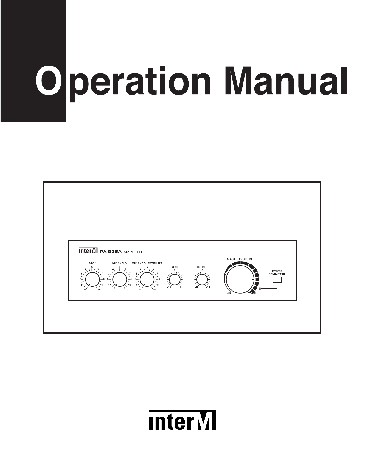
PA-935A Amplifier
Page 2

Contents
Contents
Welcome
Warning.........................................................................................................................................1
Unpacking......................................................................................................................................2
Installation
Environment....................................................................................................................................2
Important Safety Instructions.............................................................................................................2
Features............................................................................................................................................3
Accessories.....................................................................................................................................3
Front Panel ......................................................................................................................................4
Rear Panel .......................................................................................................................................5
Connecting Speakers.....................................................................................................................7
Applications ....................................................................................................................................8
Block Diagram ................................................................................................................................9
Specifications ................................................................................................................................10
Service
Procedures....................................................................................................................................11
Schematic.....................................................................................................................................11
Parts List .......................................................................................................................................11
Variations and Options ...............................................................................................................11
Warranty .......................................................................................................................................11
Page 3
1
PA-935A
AMPLIFIER
Welcome
Welcome
A personal welcome to you from the management and employees of Inter-M
All of the co-workers here at Inter-M are dedicated to providing excellent products with inherently good value,
and we are delighted you have purchased one of our products.
We sincerely trust this product will provide years of satisfactory service, but if anything is not to your complete
satisfaction, we will endeavor to make things right.
Welcome to Inter-M, and thank you for becoming part of our worldwide extended family!
RISK OF ELECTRIC SHOCK
DO NOT OPEN
CAUTION
CAUTION: TO REDUCE THE RISK OF ELECTRIC SHOCK.
DO NOT REMOVE COVER (OR BACK).
NO USER-SERVICEABLE PARTS INSIDE.
REFER SERVICING TO QUALIFIED SERVICE PERSONNEL.
WARNING
To prevent fire or shock hazard, do not
expose the unit to rain or moisture.
*Do not install this equipment in a confined space such as a book case or similar unit.
*The apparatus shall not be exposed to dripping or splashing and no objects filled with liquids, such vases, shall be placed on the apparatus.
*Worded: “WARNING FOR YOUR PROTECTION PLEASE READ THE FOLLOWING-WATER AND MOISTURE: Unit should not be used
near water(e.g. near a bathtub, washbowl, kitchen sink, laundry tub, in a wet basement, or near a swimming pool, etc). Care should be taken
so than objects do not fall and liquids are not spilled into the enclosure through openings.”
This symbol is intended to alert the user to the
presence of uninsulated “dangerous voltage” within
the product’s enclosure that may be of suf-ficient
magnitude to constitute a risk of electric shock to
persons.
This symbol is intended to alert the user to the
presence of important operation and mainte-nance
(servicing) instructions in the literature accompanying
the appliance.
Caution: To prevent electric shock do not use this (polarized) plug with
an extension cord, receptacle or other outlet unless the blades
can be fully inserted to prevent blade expo-sure.
Attentions: Pour prévenir les chocs électriques ne pas utiliser cette
fiche polarisée avec un prolongateur, une prise de courant
on une autre sortie de courant, sauf si les lames peuvent
étre insérées à fond sans en laisser aucune partie à
découvert.
Page 4

2
PA-935A
AMPLIFIER
Unpacking
Although your PA-935A is neither complicated nor difficult to operate, we recommend you take a few minutes to
read this brief manual and familiarize yourself with the important information regarding product features, setup
and operation.
As with most electronic devices, we strongly recommend you retain the original packaging. In the unlikely event
the product must be returned for servicing, the original packaging (or reasonable equivalent) is required.
Installation
Installation
Environment
Never place this product in an environment which could alter its performance or reduce its service life. Such
environments usually include high levels of heat, dust, moisture, and vibration.
Important Safety Instructions
1. Read these instructions.
2. Keep these instructions.
3. Heed all warnings.
4. Follow all instructions.
5. Do not use this apparatus near water.
6. Clean only with dry cloth.
7. Do not block any ventilation openings. Install in accordance with the manufacturer’s instructions.
8. Do not install near any heat sources such as radiators, heat registers, stoves, or other apparatus (including
amplifiers) that produce heat.
9. Do not defeat the safety purpose of the polarized or grounding-type plug. A polarized plug has two blades
with one wider than the other. A grounding type plug has two blades and a third grounding prong. The wide
blade or the third prong are provided for your safety. If the provided plug does not fit into your outlet, consult
an electrician for replacement of the obsolete outlet.
10. Protect the power cord from being walked on or pinched particularly at plugs, convenience receptacles, and
the point where they exit from the apparatus.
11. Only use attachments/accessories specified by the manufacturer.
12. Use only with the cart, stand, tripod, bracket, or table specified by the manufacturer, or sold with the apparatus.
When a cart is used, use caution when moving the cart/apparatus combination to avoid injury from tip-over.
13. Unplug this apparatus during lightning storms or when unused for long periods of time.
14. Refer all servicing to qualified service personnel. Servicing is required when the
apparatus has been damaged in any way, such as power-supply cord or plug is
damaged, liquid has been spilled or objects have fallen into the apparatus, the
apparatus has been exposed to rain or moisture, does not operate normally, or has
been dropped.
S3125A
S3125A
Page 5

3
PA-935A
AMPLIFIER
Features
Features
- HIGH POWER, LOW DISTORTION
35W of RMS power, with less than 5% THD.
- VERSATILE AND CONVENIENT
Three mixable inputs: Mic 1, Mic2/Aux, Mic3/CD/Satellite.
- CONFIGURABLE
Mic2/Aux and Mic3/CD/Satellite are individually selectable.
- TELEPHONE PAGING INPUT
Telephone input for connection with telephone system.
- PRIORITY MUTING
Mic 2/Aux and Mic3/CD/Satellite inputs mute when telephone paging and/or Mic 1 in use.
- TONE CONTROL
Separate Bass and Treble controls to tailor your sound.
Accessories
One detachable AC power cord is provided for use with this product.
Page 6
4
PA-935A
AMPLIFIER
Front Panel
Front Panel
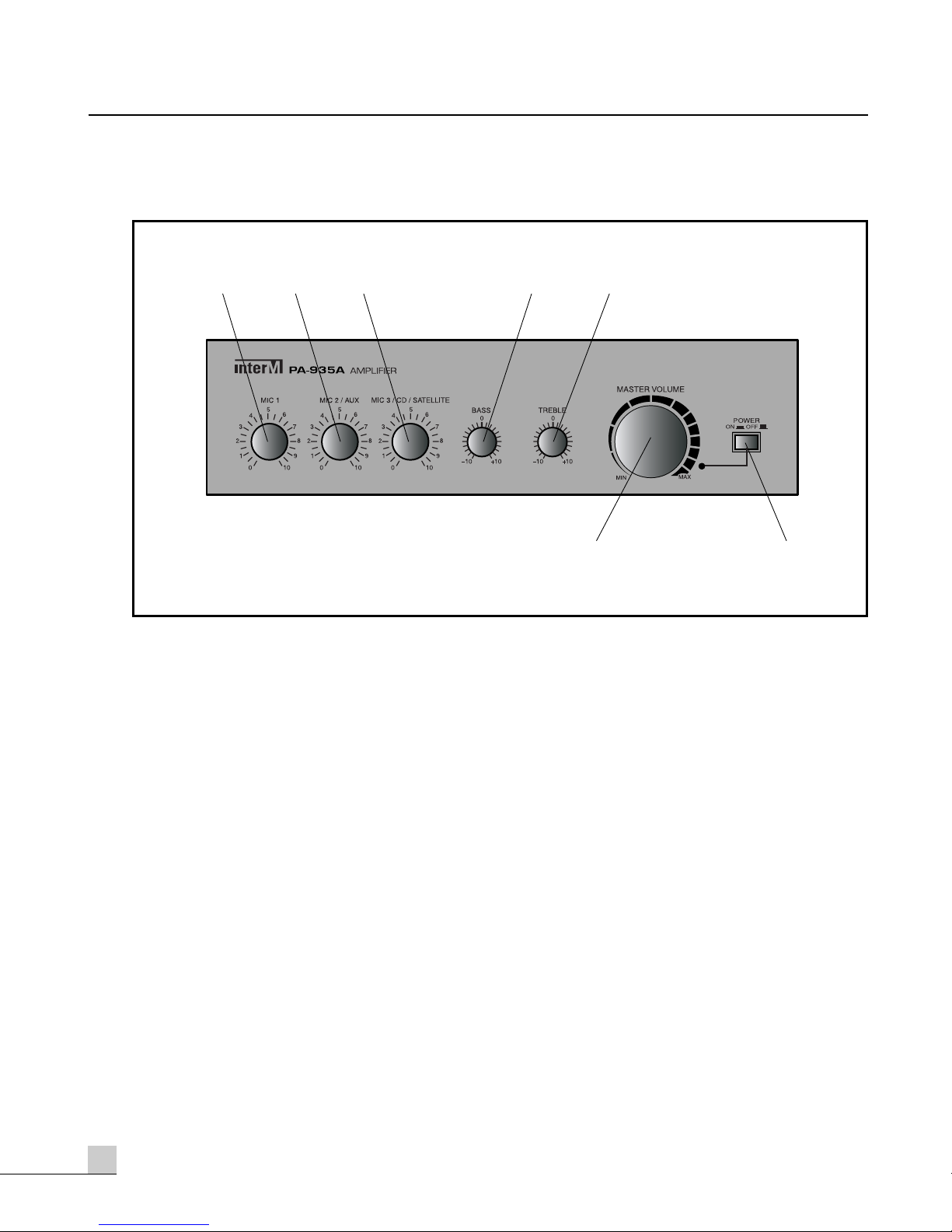
1. MIC VOLUME 1
This knob provides continuous control of the volume of Mic 1
2. MIC VOLUME 2/AUX
This knob provides continuous control of the volume of Mic 2/AUX
3. MIC VOLUME 3/CD/SATELLITE
This knob provides continuous control of the volume of Mic 3/CD/SATELLITE.
4. BASS CONTROL
This knob provides continuous control of the low frequency response, by adding up to 10dB of cut (decrease)
or boost (increase).
5. TREBLE CONTROL
This knob provides continuous control of the high frequency response, by adding up to 10dB of cut (decrease)
or boost (increase).
6. MASTER VOLUME
This knob provides continuous control of the overall volume of output.
7. POWER SWITCH
Pressing this switch turns the unit on. Pressing it again turns the unit off.
123 4 5
67
Page 7
5
PA-935A
AMPLIFIER
Rear Panel
Rear Panel
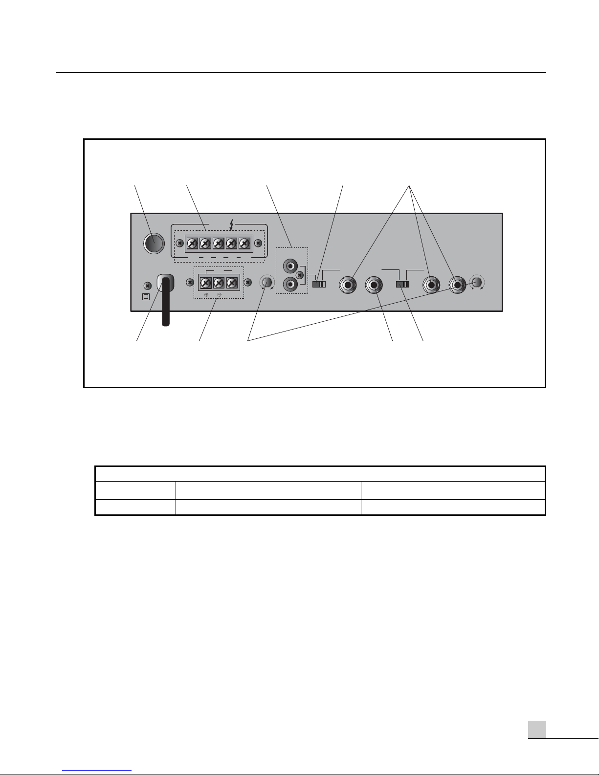
1. FUSE HOLDER
This holder contains the AC overload protection fuse. If the fuse has blown out, replace it with a fuse of the
same type and rating, as shown below.
If the fuse continues to blow, refer servicing to a qualified service technician.
2. SPEAKER OUTPUT TERMINAL
These terminals are used to connect speakers to the unit. You may select either 4Ω or 8Ω conventional
operation, or High Impedance operation at either 70V or 100V.
3. CD/SATELLITE INPUT
This RCA jack accepts a standard line-level input. Mic input 3 may be set to line-level with the use of its
associated Mic3/CD/SATELLITE switches.
4. MIC 3/CD/SATELLITE SELECTOR SWITCH
This switch is used to select between mic level and line level for Mic 3/CD/SATELLITE input.
5. MIC 1,2,3 INPUTS
These 1/4" phone jacks accept a standard mic-level or line-level input. Mic inputs 2 and 3 may be set to linelevel with the use of their associated Mic/Aux switches.
AC Fuse Ratings
Model 100V-120VAC 220V-240VAC
PA-935A 2A/250V 1A/250V
12 3 4 5
OUTPUT
TEL / MUTE
CD / SATELLITE
L
R
AUX
MIC 1MIC 2 MIC 3
MIC1 / MUTE
COM 4Ω 8Ω
70V 100V
T / P
GND
678 910
Page 8

6
PA-935A
AMPLIFIER
6. AC CORD
Connect this cable to your AC outlet.
7. TELEPHONE IN TERMINAL
These terminals are used to connect to a telephone exchange system for paging purposes.
NOTE: When signal is present on the Telephone Input terminal, all other input signals (except Mic 1) are
muted.
8. MUTE CONTROLS
When signal is present at Mic 1 or Telephone input, all other inputs are muted. These controls adjust the level
of Mic 1 and Telephone output when muting is in use.
9. AUX INPUT
This input is used for connecting line-level sources, such as CD or cassette deck. When using this input, the
respective Mic/AUX switch must be set to its AUX setting.
10. MIC 2/AUX SELECTOR SWITCH
This switch is used to select between mic level and line level for Mic 2/AUX input.
Page 9
7
PA-935A
AMPLIFIER
Connecting Speakers
Connecting Speakers
Before connecting speakers to your PA-935A unit, be sure to disconnect the AC power cable. Make certain that
the total impedance is not less than the rated impedance indicated.
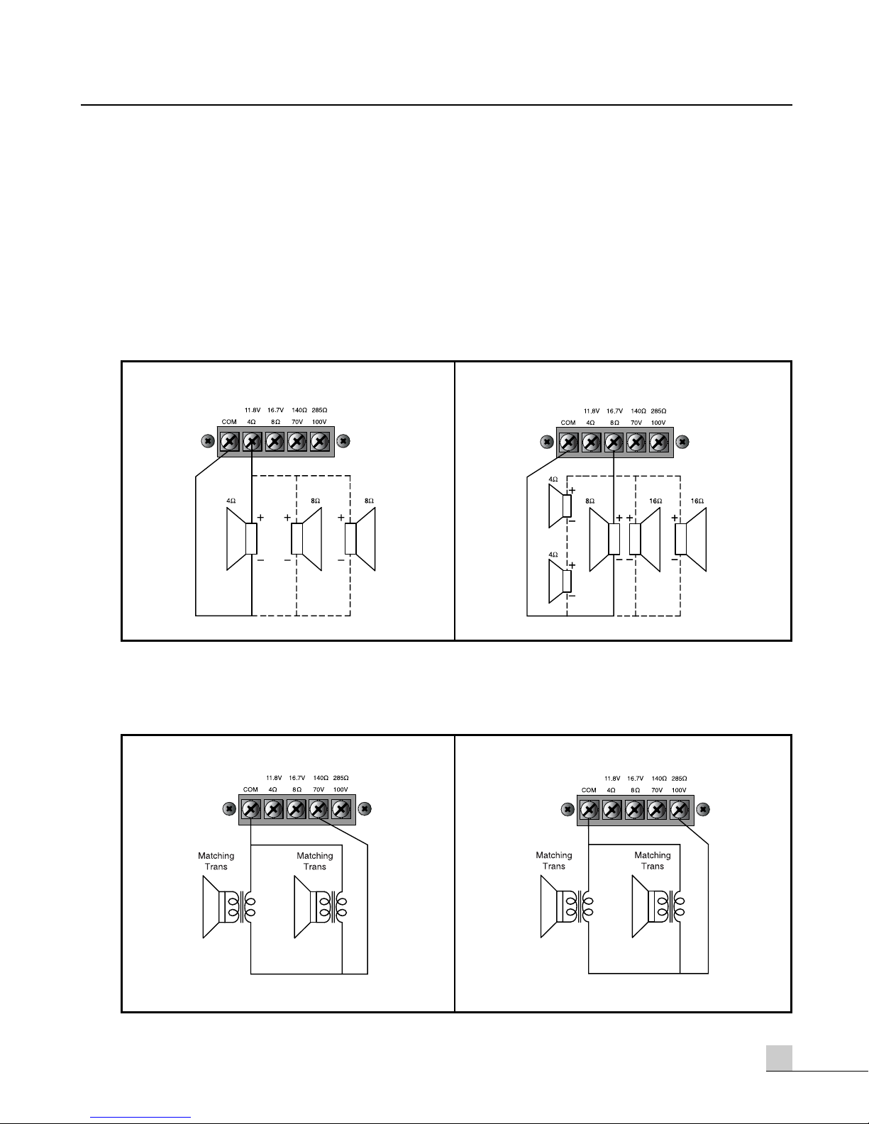
For 4Ω low-impedance speakers, connect in parallel, with the negative (-) connectors to the 4Ω terminal and the
positive (+) connectors to the COM terminal. See Figure 2-1 below.
For 8Ω low-impedance speakers, connect in parallel, with the negative (-) connectors to the 8Ω terminal and the
positive (+) connectors to the COM terminal. See Figure 2-2 below.
For high-voltage distributed systems, connect with matching transformer as per Figures 2-3 and 2-4 below. Be
certain that the total impedance does not equal less than the rated impedance.
- FOR 70V TERMINAL
Be sure that total impedance is not less than rated impedance. Be sure that total impedance is not less than rated impedance.
- FOR 100V TERMINAL
- FOR 4Ω TERMINAL - FOR 8Ω TERMINAL
Page 10
8
PA-935A
AMPLIFIER
Applications
Applications
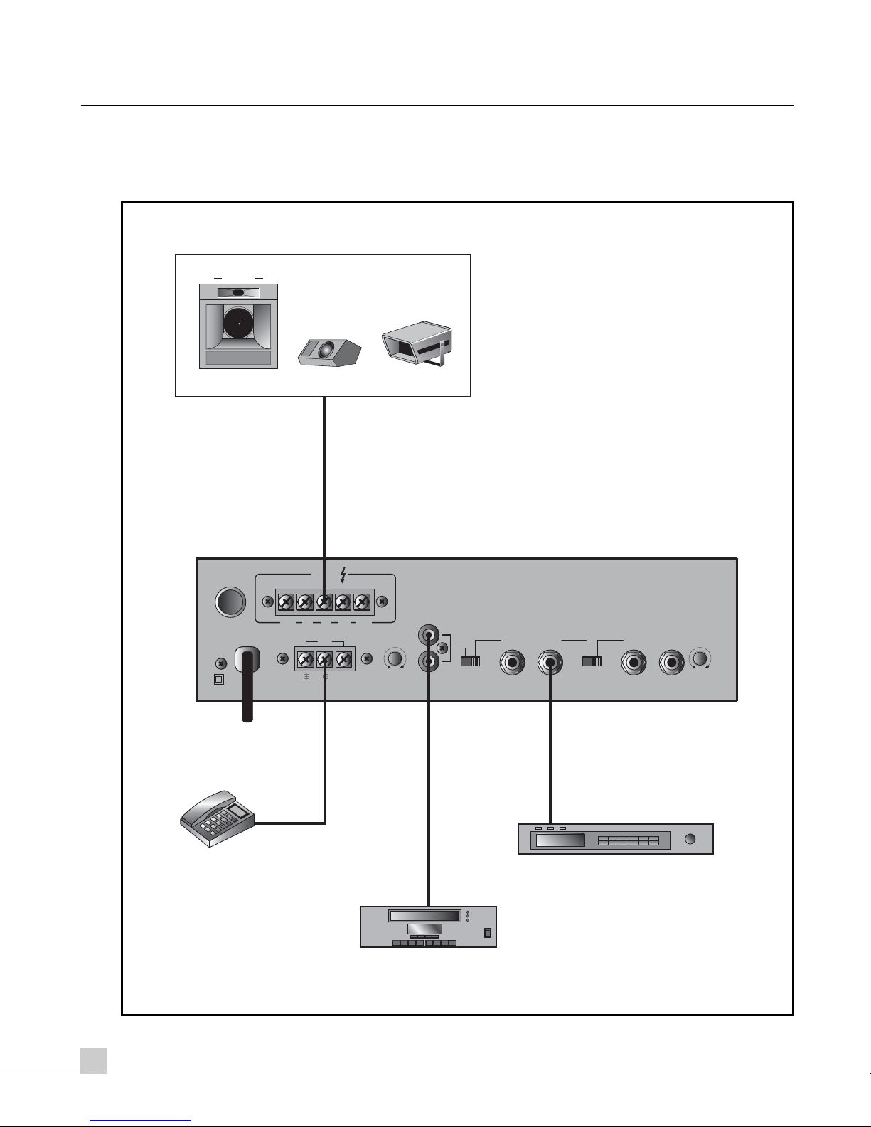
SPEAKERS
TELEPHONE
EXCHANGE SYSTEM
OUTPUT
COM 4Ω 8Ω
T / P
70V 100V
GND
TEL / MUTE
CD / SATELLITE
L
R
CD/SATELLITE
AUX
MIC 1MIC 2 MIC 3
MIC1 / MUTE
TUNER
Page 11
9
PA-935A
AMPLIFIER
Block Diagram
Block Diagram
Page 12

10
PA-935A
AMPLIFIER
Specifications
Specifications
- ELECTRICAL
Rated Output Power (at THD: 5%)..................................................................................................35W(RMS)
Frequency Response(±3dB)
MIC 1, 2, 3.........................................................................................................................150Hz-12kHz
AUX .....................................................................................................................................80Hz-15kHz
CD/SATELLITE.......................................................................................................................80Hz-15kHz
TELEPHONE..........................................................................................................................330Hz-3kHz
Total Harmonic Distortion (at Rated Output, 1kHz).......................................................................Less Than 5%
Signal to Noise Ratio
MIC 1, 2, 3 .....................................................................................................................Better than 55dB
AUX, CD/SATELLITE, TELEPHONE.....................................................................................Better than 65dB
Input Sensitivity/Impedance
MIC 1, 2, 3 ..........................................................................................................................-50dB/600Ω
AUX.....................................................................................................................................-15dB/10kΩ
CD/SATELLITE..........................................................................................................................0dB/10kΩ
TELEPHONE .......................................................................................................................0.775V/600Ω
Output Voltage/Impedance..................................................4Ω/11.8V, 8Ω/16.7V, 140Ω/70V, 285Ω/100V
- GENERAL
Power Source ................................................................................100–120VAC or 220–240VAC; 50/60Hz
..............................................................(Supplied AC mains transformer depends on country requirements)
Power Consumption ..............................................................................................................................40W
Weight......................................................................................................................................4.4kg/9.7lb
Dimensions.......................................................................290(W)x76(H)x185(D)mm/11.4(W)x3(H)x7.3(D)in
* Specifications and design subject to change without notice.
Page 13

11
PA-935A
AMPLIFIER
Service
Service
Procedures
Ensure the problem is not related to operator error, or system devices that are external to this unit. Information
provided in the troubleshooting portion of this manual may help with this process. Once it is certain that the
problem is related to the product contact your warranty provider as described in the warranty section of this
manual.
Schematic
A Schematic is available by contacting your warranty provider.
Parts List
A Parts List is available by contacting your warranty provider.
Variations and Options
Variations and Options
Variations
Products supplied through legitimate sources are compatible with local AC power requirements.
Options
No optional items are available for this product.
Warranty
Warranty
Warranty terms and conditions vary by country and may not be the same for all products. Terms and conditions
of warranty for a given product may be determined first by locating the appropriate country which the product
was purchased in, then by locating the product type.
To obtain specific warranty information and available service locations contact Inter-M directly(in Korea or the
USA) or the authorized Inter-M Distributor for your specific country or region.
Page 14

Inter-M, Ltd. (Korea) began operations in 1983.
Since then, Inter-M has grown to become one of the largest manufacturers
of professional audio and commercial sound electronics equipment in the world.
Inter-M has gained worldwide recognition for its own branded products,
as well as private label manufacturing of electronics sold under other names (OEM).
The company is no longer just a Korean company, but rather a global company
that is truly international in scope, with factories and offices in Korea and China,
and sales and marketing operations located in Japan, Europe, and the U.S.A.
With more than 850 employees around the globe,
Inter-M is well-poised for further growth and expansion.
INTER-M AMERICAS, INC.
1 EAST BEACON LIGHT LANE CHESTER, PA USA 19013-4409
TEL : 1-610-874-8870, FAX : 1-610-874-8890
Home Page : http://www.inter-m.net, E-mail : [email protected]
INTER-M Corporation
SEOUL OFFICE:653-5 BANGHAK-DONG, DOBONG-KU, SEOUL, KOREA
TEL : 82-2-2289-8140~8, FAX : 82-2-2289-8149
Home Page : http://www.inter-m.com, E-mail : [email protected]
December 2005 9007203200 A
MADE IN CHINA
 Loading...