

Page 1
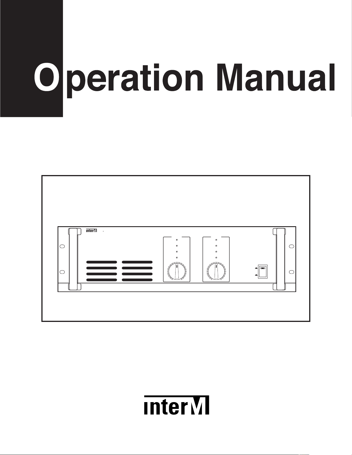
PA-2312
ON
10
9
11
CLIP
-10dB
-40dB
P
R
OT
12
13
15
17
19
2
2
29
5
4
0
1
2
3
4
5
6
7
8
00
C
HANNEL 1
10
9
11
CLIP
-10dB
-40dB
P
ROT
12
13
15
17
19
2
2
29
5
4
0
1
2
3
4
5
6
7
8
00
C
HANNEL 2
POWER
OFF
PA
2
312
P
UBLIC ADDRESS 2 CH POWER AMPLIFIER
Public Address 2 CH Power Amplifier
* Rack mount products in the Western Hemisphere(North America, South America,
and the Caribbean) do not have handles installed due to customer preference.
Page 2

Contents
Contents
Welcome
arning.........................................................................................................................................1
W
Unpacking......................................................................................................................................2
Installation
Environment....................................................................................................................................2
Important Safety Instructions.............................................................................................................2
Features............................................................................................................................................3
Accessories.....................................................................................................................................3
Operation ........................................................................................................................................3
Front Panel ......................................................................................................................................4
Rear Panel .......................................................................................................................................5
Connecting Speakers.....................................................................................................................7
Applications ....................................................................................................................................8
Block Diagram ................................................................................................................................9
Specifications ................................................................................................................................10
Service
Procedures....................................................................................................................................11
Schematic.....................................................................................................................................11
Parts List .......................................................................................................................................11
Variations and Options ...............................................................................................................11
Warranty .......................................................................................................................................11
Page 3
UBLIC ADDRESS 2 CH POWER AMPLIFIER
P
Welcome
Welcome
A personal welcome to you from the management and employees of Inter-M
All of the co-workers here at Inter-M are dedicated to providing excellent products with inherently good value,
and we are delighted you have purchased one of our products.
We sincerely trust this product will provide years of satisfactory service, but if anything is not to your complete
satisfaction, we will endeavor to make things right.
Welcome to Inter-M, and thank you for becoming part of our worldwide extended family!
his symb ol is inte nd ed to aler t the us er to t he
T
CAUTION
RISK OF ELECTRIC SHOCK
DO NOT OPEN
presence of uninsulated “dangerous voltage” within
the product’s enclosure that may be of suffi cient
magnitude to constitute a risk of electric shock to
persons.
AUTION: TO REDUCE THE RISK OF ELECTRIC SHOCK.
C
DO NOT REMOVE COVER (OR BACK).
NO USER-SERVICEABLE PARTS INSIDE.
REFER SERVICING TO QUALIFIED SERVICE PERSONNEL.
Caution: To prevent electric shock do not use this (polarized) plug with
Attentions: Pour prévenir les chocs électriques ne pas utiliser cette
WARNING
To prevent fire or shock hazard, do not
expose the unit to rain or moisture.
*Do not install this equipment in a confined space such as a book case or similar unit.
*The apparatus shall not be exposed to dripping or splashing and no objects filled with liquids, such vases, shall be placed on the apparatus.
*Worded: “WARNING FOR YOUR PROTECTION PLEASE READ THE FOLLOWING-WATER AND MOISTURE: Unit should not be used
near water(e.g. near a bathtub, washbowl, kitchen sink, laundry tub, in a wet basement, or near a swimming pool, etc). Care should be taken
so than objects do not fall and liquids are not spilled into the enclosure through openings.”
This sy mb ol is inte nd ed to a le rt the us er to t he
presence of important operation and maintenance
(servicing) instructions in the literature accompanying
the appliance.
an extension cord, receptacle or other outlet unless the blades
can be fully inserted to prevent blade exposure.
fiche polarisée avec un prolongateur, une prise de courant
on une autre sortie de courant, sauf si les lames peuvent
étre in sé ré es à fond s an s en laisser au cu ne pa rt ie à
découvert.
PA-2312
1
Page 4

UBLIC ADDRESS 2 CH POWER AMPLIFIER
S
3125A
P
Unpacking
Although your PA-2312 Power Amplifier is neither complicated nor difficult to operate, we recommend you take
a few minutes to read this brief manual and familiarize yourself with the important information regarding
product features, setup and operation.
As with most electronic devices, we strongly recommend you retain the original packaging. In the unlikely event
the product must be returned for servicing, the original packaging (or reasonable equivalent) is required.
Installation
Installation
Environment
Never place this product in an environment which could alter its performance or reduce its service life. Such
environments usually include high levels of heat, dust, moisture, and vibration.
Important Safety Instructions
1. Read these instructions.
2. Keep these instructions.
3. Heed all warnings.
4. Follow all instructions.
5. Do not use this apparatus near water.
6. Clean only with dry cloth.
7. Do not block any ventilation openings. Install in accordance with the manufacturer’s instructions.
8. Do not install near any heat sources such as radiators, heat registers, stoves, or other apparatus (including
amplifiers) that produce heat.
9. Do not defeat the safety purpose of the polarized or grounding-type plug. A polarized plug has two blades
with one wider than the other. A grounding type plug has two blades and a third grounding prong. The wide
blade or the third prong are provided for your safety. If the provided plug does not fit into your outlet, consult
an electrician for replacement of the obsolete outlet.
10. Protect the power cord from being walked on or pinched particularly at plugs, convenience receptacles, and
the point where they exit from the apparatus.
11. Only use attachments/accessories specified by the manufacturer.
12. Use only with the cart, stand, tripod, bracket, or table specified by the manufacturer, or sold with the apparatus.
When a cart is used, use caution when moving the cart/apparatus combination to avoid injury from tip-over.
13. Unplug this apparatus during lightning storms or when unused for long periods of time.
14. Refer all servicing to qualified service personnel. Servicing is required when the
apparatus has been damaged in any way, such as power-supply cord or plug is
damaged, liquid has been spilled or objects have fallen into the apparatus, the
apparatus has been exposed to rain or moisture, does not operate normally, or has
been dropped.
S3125A
2
PA-2312
Page 5

Features
Features
- HIGH POWER, LOW DISTORTION
20W of RMS power with less than 1% THD.
1
- ADVANCED PROTECTION CIRCUITRY
Thermal and current overload protection, power-on delay and automatic idling circuitry for component and
loudspeaker protection.
- BATTERY BACKUP
Can be powered by 24VDC battery for emergency backup and true portability.
- SLIM DESIGN, COMPACT SIZE
Streamlined design fits in a compact 3RU space.
Accessories
One detachable AC power cord is provided for use with this product.
UBLIC ADDRESS 2 CH POWER AMPLIFIER
P
Operation
Operation
Make certain that speakers and input sources are properly connected before switching on.
Keep volume levels at minimum gain before switching on.
NOTE: The system’s operation is delayed by approximately three seconds after pressing the AC Mains power
switch. This is due to the built-in protection circuitry, designed to protect speakers and other system
components.
PA-2312
3
Page 6

UBLIC ADDRESS 2 CH POWER AMPLIFIER
P
UBLIC ADDRESS 2 CH POWER AMPLIFIER
PA-2312
ON
1
1
0
911
C
LIP
-
10dB
-40dB
P
ROT
1
2
1
3
15
17
19
2
2
29
54
0
1
2
3
4
5
6
7
8
00
C
HANNEL 1
1
0
911
C
LIP
-
10dB
-40dB
P
ROT
1
2
1
3
15
17
19
2
2
29
54
0
1
2
3
4
5
6
7
8
00
C
HANNEL 2
POWER
OFF
43
2
5
P
Front Panel
Front Panel
1. PROTECTION INDICATOR
This LED indicates the state of the amplifier’s protection circuitry. When the Protection LED is on (illuminated),
the protection circuitry is active, indicating that the unit is not operating normally. This is typically due to
overheating or power limiting. Please check the Input and Output condition of the amplifier.
Note that the Protection Indicator lights for approximately six seconds when the amplifier is first powered on.
2. OUTPUT LEVEL INDICATORS
These LEDs indicate the amplifier’s output status, lighting when audio signal is received. The red CLIP LED
indicates an excessive output level. Do not operate the unit with the CLIP LED steadily on (illuminated).
3. POWER SWITCH
Pushing this switch up switches the unit on. Pushing it down switches the unit off.
4. POWER LED
When the unit is powered on, the Power LED will glow steadily.
5. INPUT ATTENUATORS
These are controls for regulating each channel’s output level. Clockwise rotation increases gain.
4
PA-2312
Page 7

Rear PanelRear Panel
1
45 67 8
2 3
UBLIC ADDRESS 2 CH POWER AMPLIFIER
P
1. AC INPUT POWER
Connect the supplied standard AC input cable here.
2. SPEAKER OUTPUT TERMINALS
These terminals are provided for connecting speakers to the unit. Make certain the combined impedance of
the speakers is equal to or higher than the rated output impedance of the amplifier.
The impedance and output voltage are as follows.
•USA/CANADA & Associated Version •EC & Associated, JAPAN Version
Impedance 4Ω 5.2Ω 41Ω
Output Voltage 22V 25V 70V
3. FAN VENTS
These vents provide hot air flow out of the unit. It is important to keep them free of obstructions, to prevent the
unit from overheating. It is also important to operate the unit in a dust-free environment.
4. AC FUSE HOLDER
This holder contains the AC overload protection fuse. If the fuse has blown out, replace it with a fuse of the
same type and rating.
If the fuse continues to blow, please refer servicing to qualified service personnel.
5. HIGH-PASS FILTER SWITCH
This switch activates the high-pass filter circuit, which reduces excessive low frequency content to protect
speakers and components.
Impedance 4Ω 41Ω 83Ω
Output Voltage 22V 70V 100V
PA-2312
5
Page 8

UBLIC ADDRESS 2 CH POWER AMPLIFIER
P
6. AUDIO INPUTS
Balanced input connectors are provided on both male and female XLR jacks for convenience.
7. GROUND LIFT SWITCH
This switch provides for connection or disconnection of the amplifier’s ground to AC “earth” ground, to
prevent noise from ground loops. Under most circumstances, this switch should be set to FRAME position.
8. DC INPUT TERMINALS
These terminals are provided for the connection of backup battery. Connect a 24VDC battery source to these
terminals. Make certain the red terminal is connected to the battery’s positive (+) side, and the black terminal
to the battery’s negative (–) side.
6
PA-2312
Page 9

Connecting Speakers
OUTPUT
CH 1
CH 2
COM
OUTPUT
CH 1
CH 2
Connecting Speakers
Before connecting speakers to your PA-2312 unit, be sure to disconnect the AC power cable. Make certain that
he total impedance is not less than the rated impedance indicated.
t
For 4Ω speakers, connect the positive (+) connector to the 22V(4Ω) terminal and the negative (–) connectors to
the COM terminal.
For high-voltage distributed systems, connect with matching transformer to the COM and either 70V or 100V
terminals. Be certain that the total impedance does not equal less than the rated impedance.
- USA/CANADA & Associated Version
UBLIC ADDRESS 2 CH POWER AMPLIFIER
P
- EC & Associated, JAPAN Version
PA-2312
7
Page 10

P
SWED 3
(
2000W)
SWED 2
(
2000W)
SWED 1
(
2000W)
UNSWED
(
700W)
E
MERGENCY
AC FUSE
T
2AL/250V
UNSWITCHED
D
C OUT 24V,1A MAX
REMOTE
C-SW-H
GND
BATTERY
INPUT 24V
( )
( )
( )
SWITCHED
D
C OUT 24V
5A MAX
(
)
(
)
SWITCHED DC OUT 24V
(
RACK ONLY)
(AMP ONLY)
AC INPUT
230V 50Hz, 217VA
www.inter-m.com
DC FUSE
T
5AL/250V
S
N
D
CINPUT
2
4V
L
INE
21 21
F
USE
T
400mAL
/
2
50V
INSER
www.inter-m.com
TINSERT
RECOUTPUT PRIORITY INPUT
MIC
MIC MIC MIC MIC MIC MIC MIC
CH2
OUTPUT OUTPUT
MUTE
ON
OFF
S
N
AC INPUT
230V 50Hz
9.8W
~
L
INE LINE LINE LINE LINE LINE
CH5 CH 4 CH 3 CH 2 CH1CH8 CH7 CH6
CH1
CH 12 CH10CH 11 CH 9
OC03OC03
0
210
CH16 CH15 CH14 CH13 CH12 CH11 CH10 CH9 CH8 CH7 CH6 CH5 CH4 CH3 CH2 CH1
REMOTE
S
N
(
)
(
)
(
)
(
)
AMP IN 1
AMP IN 2
ALL
GROUP1
GROUP2
TIMER
DC INPUT
2
4V
O
C03OC03
0
210
A
C INPUT : 230V 50Hz, 139VA
FUSE : T1AL / 250V
BATTERY IN
( )
( )
MADE IN KOREA
BATTERY CHARGER
MODEL NO. PB-9207A
~
NO USER SERVICEABLE PARTS INSIDE.
RISQUE DE CHOC ELECTRIQUE NE
CTRIC SHOCK, DO NOT REMOVE COVER.
R
EFER SERVICING TO QUALIFIED SERVICE
C
AUTION;
AVIS;
TOREDUCE THE RISK OF FIRE
REPLACE ONLY WITH SAME TYPE FUSE.
CAUTION;
TOREDUCE THE RISK OF ELE-
PERSONNEL.
PAS OUVRIR.
UTILISER UN FUSIBLE DE RECHANGE DE
M
EME TYPE.
S
N
MIC
PS-9116
SPEAKER
PB-9207A
AC INPUT
BATTERY
(DC24V)
PD-9359E
PA-2312
TURN TABLE
(CD, TUNER.....)
PP-9214
ON
( )
( )
BATTERY
(DC24V)
( )
( )
Applications
Applications
UBLIC ADDRESS 2 CH POWER AMPLIFIER
8
PA-2312
Page 11

Block Diagram
Block Diagram
UBLIC ADDRESS 2 CH POWER AMPLIFIER
P
PA-2312
9
Page 12

UBLIC ADDRESS 2 CH POWER AMPLIFIER
P
Specifications..............................................................0dB=0.775Vrms
Specifications
- ELECTRICAL
Rated Output (RMS, THD 1%, 1kHz).....................................................................................................120W
Input Sensitivity/Impedance.............................................................................................1V/10kΩ, Balanced
T.H.D........................................................................................................................................Less than 1%
S/N....................................................................................................................................Better than 95dB
High Pass Filter.......................................................................................................................-3dB at 400Hz
Channel Separation ..............................................................................................................Less than –70dB
Output Voltage/Impedance........................................................EC, JAPAN: 4Ω/22V, 41Ω/70V, 83Ω/100V
......................................................................................USA/CANADA: 4Ω/22V, 5.2Ω/25V, 41Ω/70V
- GENERAL
Power Source....................................................................100–120VAC or 220–240VAC; 50/60Hz, 24VDC
..............................................................(Supplied AC mains transformer depends on country requirements)
Power Consumption(1/8 Power) ..........................................................................................................290W
Weight..................................................................................................................................17.9kg/39.5lb
Dimensions..............................................................482(W) x 132(H) x 280(D)mm/19(W) x 5.2(H) x 11(D)in
* Specifications and design subject to change without notice.
10
PA-2312
Page 13

UBLIC ADDRESS 2 CH POWER AMPLIFIER
P
Service
Service
Procedures
Ensure the problem is not related to operator error, or system devices that are external to this unit. Information
provided in the troubleshooting portion of this manual may help with this process. Once it is certain that the
problem is related to the product contact your warranty provider as described in the warranty section of this
manual.
Schematic
A Schematic is available by contacting your warranty provider.
Parts List
A Parts List is available by contacting your warranty provider.
Variations and Options
Variations and Options
Variations
Products supplied through legitimate sources are compatible with local AC power requirements.
Options
No optional items are available for this product.
Warranty
Warranty
Warranty terms and conditions vary by country and may not be the same for all products. Terms and conditions
of warranty for a given product may be determined first by locating the appropriate country which the product
was purchased in, then by locating the product type.
To obtain specific warranty information and available service locations contact Inter-M directly(in Korea or the
USA) or the authorized Inter-M Distributor for your specific country or region.
PA-2312
11
Page 14

N
OTE
Page 15

Inter-M, Ltd. (Korea) began operations in 1983.
Since then, Inter-M has grown to become one of the largest manufacturers
of professional audio and commercial sound electronics equipment in the world.
Inter-M has gained worldwide recognition for its own branded products,
as well as private label manufacturing of electronics sold under other names (OEM).
The company is no longer just a Korean company, but rather a global company
that is truly international in scope, with factories and offices in Korea and China,
and sales and marketing operations located in Japan, Europe, and the U.S.A.
With more than 850 employees around the globe,
Inter-M is well-poised for further growth and expansion.
Inter-M Americas, INC.
13875 ARTESIA BLVD. CERRITOS, CA 90703 USA
TEL : +1-562-921-0313, FAX : +1-562-921-0370
Home Page : http://www.inter-m.net, E-mail : info@inter-m.net
Inter-M Corporation
SEOUL OFFICE:653-5 BANGHAK-DONG, DOBONG-KU, SEOUL, KOREA
TEL : +82-2-2289-8140~8, FAX : +82-2-2289-8149
Home Page : http://www.inter-m.com, E-mail : overseas@inter-m.com
December 2005 9007907712 B
MADE IN KOREA
 Loading...