

Page 1
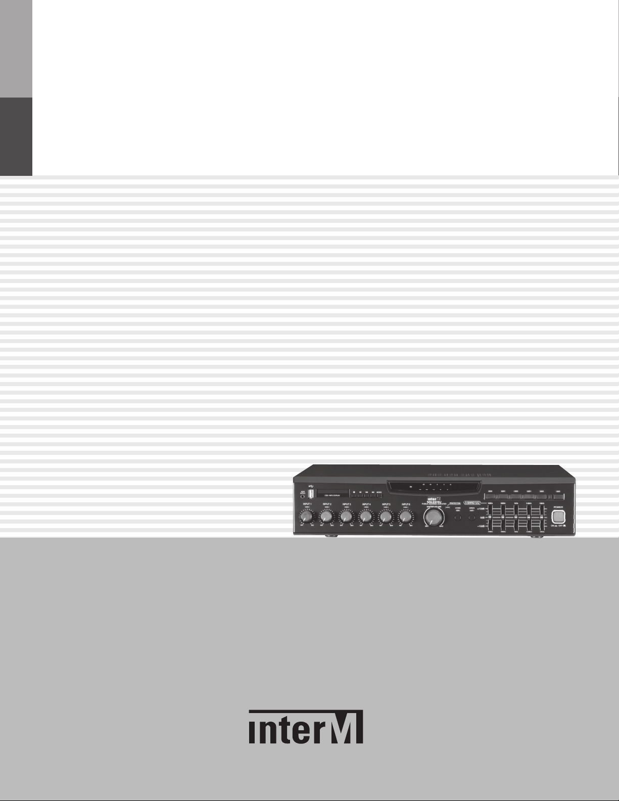
Operation Manual
Public Address Amplifier
MA-206U/212U/224U
Page 2
PUBLIC ADDRESS AMPLIFIER
Welcome
Welcome
A personal welcome to you from the management and employees of Inter-M
All of the co-workers here at Inter-M are dedicated to providing excellent products with inherently good value,
and we are delighted you have purchased one of our products.
We sincerely trust this product will provide years of satisfactory service, but if anything is not to your complete
satisfaction, we will endeavor to make things right.
Welcome to Inter-M, and thank you for becoming part of our worldwide extended family!
This symbol is int ended to ale rt the user to the
CAutION
RISK OF ELECTRIC SHOCK
DO NOT OPEN
CAUTION: TO REDUCE THE RISK OF ELECTRIC SHOCK.
DO NOT REMOVE COVER (OR BACK).
NO USER-SERVICEABLE PARTS INSIDE.
REFER SERVICING TO QUALIFIED SERVICE PERSONNEL.
Caution: To prevent electric shock do not use this (polarized) plug with
Attentions: Pour prévenir les chocs électriques ne pas utiliser cette
WARNING
To prevent fire or shock hazard, do not
expose the unit to rain or moisture.
*WARNING FOR YOUR PROTECTION PLEASE READ THE FOLLOWING-WATER AND MOISTURE: Unit should not be used near water(e.g.
near a bathtub, washbowl, kitchen sink, laundry tub, in a wet basement, or near a swimming pool, etc). Care should be taken so than objects do
not fall and liquids are not spilled into the enclosure through openings.
*CLASS 2 WIRING (Adjacent to speaker terminal): The speaker output of this apparatus can exceed 10 Watts and could be a shock injury.
Connection to speakers should be performed by a skilled person.
*Do not install this equipment in a confined space such as a book case or similar unit.
*This apparatus shall not be exposed to dripping or splashing and no objects filled with liquids, such vases, shall be placed on the apparatus.
*This apparatus shall be connected to a mains socket outlet with a protective earthing connection.
It has heed to be easy to disconnect the device. To disconnect the device from power, separate AC input cable from inlet or unplug the AC Cord.
*
CAutION
*These servicing instructions are for use by qualified service personnel only. To reduce the risk of electric shock, do not perform any servicing
other than that contained in the operating instructions unless you are qualified to do so.
NOtE
*This equipment has been tested and found to comply with the limits for a Class A digital device, pursuant to Part 15 of the FCC Rules. These limits are
designed to provide reasonable protection against harmful interference when the equipment is operated in a commercial environment. This equipment
generates, uses, and can radiate radio frequency energy and, if not installed and used in accordance with the instruction manual, may cause harmful
interference to radio communications. Operation of this equipment in a residential area is likely to cause harmful interference in which case the user will
be required to correct the interference at his own expense.
presence of uninsulated “dangerous voltage” within
the product’s enclosur e that ma y be of sufficient
magnitude to constitute a risk of electric shock to
persons.
This symbol is int ended to ale rt the user to the
presence of important operation and maintenance
(servicing) instructions in the literature accompanying
the appliance.
an extension cord, receptacle or other outlet unless the blades
can be fully inserted to prevent blade exposure.
fiche polarisée avec un prolongateur, une prise de courant
on une autre sortie de courant, sauf si les lames peuvent
étre inséré es à fond sans en lai sser aucune par tie à
découvert.
Page 3

PUBLIC ADDRESS AMPLIFIER
Contents
Contents
Unpacking .......................................................................................................................................2
Installation
Environment....................................................................................................................................2
Important Safety Instructions.............................................................................................................2
Features............................................................................................................................................3
Accessories.....................................................................................................................................3
Operation ........................................................................................................................................3
Front Panel ......................................................................................................................................4
Rear Panel .......................................................................................................................................7
Connecting Speakers.....................................................................................................................9
Applications ..................................................................................................................................10
Block Diagram ..............................................................................................................................11
Specifications ................................................................................................................................12
Service
Procedures....................................................................................................................................14
Schematic.....................................................................................................................................14
Parts List .......................................................................................................................................14
Variations and Options ...............................................................................................................14
Warranty .......................................................................................................................................14
MA-206U/212U/224U
1
Page 4

UBLIC ADDRESS AMPLIFIER
S3125A
P
Unpacking
Unpacking
Although your MA-206U/212U/224U is neither complicated nor difficult to operate, we recommend you take a
few minutes to read this brief manual and familiarize yourself with the important information regarding product
features, setup and operation.
As with most electronic devices, we strongly recommend you retain the original packaging. In the unlikely event
the product must be returned for servicing, the original packaging (or reasonable equivalent) is required.
Installation
Installation
Environment
Never place this product in an environment which could alter its performance or reduce its service life. Such
environments usually include high levels of heat, dust, moisture, and vibration.
IMPORTANT SAFETY INSTRUCTIONS
1. Read these instructions.
2. Keep these instructions.
3. Heed all warnings.
4. Follow all instructions.
5. Do not use this apparatus near water.
6. Clean only with dry cloth.
7. Do not block any ventilation openings. Install in accordance with the manufacturer’s instructions.
8. Do not install near any heat sources such as radiators, heat registers, stoves, or other apparatus (including
amplifiers) that produce heat.
9. Do not defeat the safety purpose of the polarized or grounding-type plug. A polarized plug has two blades
with one wider than the other. A grounding type plug has two blades and a third grounding prong. The wide
blade or the third prong are provided for your safety. If the provided plug does not fit into your outlet, consult
an electrician for replacement of the obsolete outlet.
10. Protect the power cord from being walked on or pinched particularly at plugs, convenience receptacles, and
the point where they exit from the apparatus.
11. Only use attachments/accessories specified by the manufacturer.
12. Use only with the cart, stand, tripod, bracket, or table specified by the manufacturer, or sold with the apparatus.
When a cart is used, use caution when moving the cart/apparatus combination to avoid injury from tip-over.
13. Unplug this apparatus during lightning storms or when unused for long periods of time.
14. Refer all servicing to qualified service personnel. Servicing is required when the
apparatus has been damaged in any way, such as power-supply cord or plug is
damaged, liquid has been spilled or objects have fallen into the apparatus, the
apparatus has been exposed to rain or moisture, does not operate normally, or has
been dropped.
S3125A
2
MA-206U/212U/224U
Page 5

Features
Features
- A PUBLIC ADDRESS AMPLIFIER WITH RATED OUTPUT OF 60W/120W/240W
TAKE UP THE DIGITAL AMPLIFIER CIRCUIT WITH HIGH EFFICIENCY OF THE RATED
POWER 60W/120W/240W, HIGH RELIABILITY, LOW WEIGHT AND LOW TEMPERATURE.
- SUPPLY POWER BY SMPS
TAKE UP SMPS (SWITCHING MODE POWER SUPPLY) FOR LOW ELECTRIC POWER AND LOW WEIGHT.
- VARIOUS INPUT CONTROL FUNCTION
CONTROL THE EACH INPUT CHANNEL LEVEL USING THE SOUND CONTROL VOLUME OF INPUT 1~6.
- INPUT SIGNAL LEDS
EASY TO CHECK THE INPUTTED SIGNAL TO INPUT 1~6.
- 5 BAND GRAPHIC EQUALIZER
THIS SYSTEM IS PROVIDED THE 5 BANDS EQUALIZER.
YOU CAN CONTROL THE TONE EACH FREQUENCY BY USING THEM.
PUBLIC ADDRESS AMPLIFIER
- SPEAKER SELECTOR
6 SPEAKER SELECTOR SWITCHES ARE PROVIDED TO ENABLE YOU TO SELECT 5 SPEAKERS INDIVIDUALLY
OR TOTALLY.
- ANNOUNCEMENT CHIME AND SIREN
- VCA(VOLTAGE CONTROLLED AMPLIFIER)
- EXT MUTE, EXT CHIME AND TEL IN FUNCTION
- 10-DOT LED LEVEL METER
- USB-MP3 PLAYER & LCD DISPLAY FUNCTION
( MP3, WAV, WMA FILE FORMAT SUPPORT)
Accessories
One detachable AC power cord and Φ3.5mm audio cable are provided for use with this product.
Operation
Operation
1. Do not connect the AC power until step 4.
The AC mains POWER switch should be in the OFF position.
2. Adjust the MASTER and all INPUT 1~6 volume controls of the MIN position (turn counterclockwise).
3. Adjust the graphic equalizer so that all slides are set to the 0dB position.
4. Connect the OUTPUTS to the speaker load according to the mode of operation determined in
the previous step.
5. Depress the AC mains POWER switch to the ON position. The POWER ON indicator will illuminate.
6. The product is ready for operation, Slowly increase the LEVEL control to the desired operating level.
Avoid illuminating the PEAK indicator and do not apply too much power to the speakers.
MA-206U/212U/224U
3
Page 6
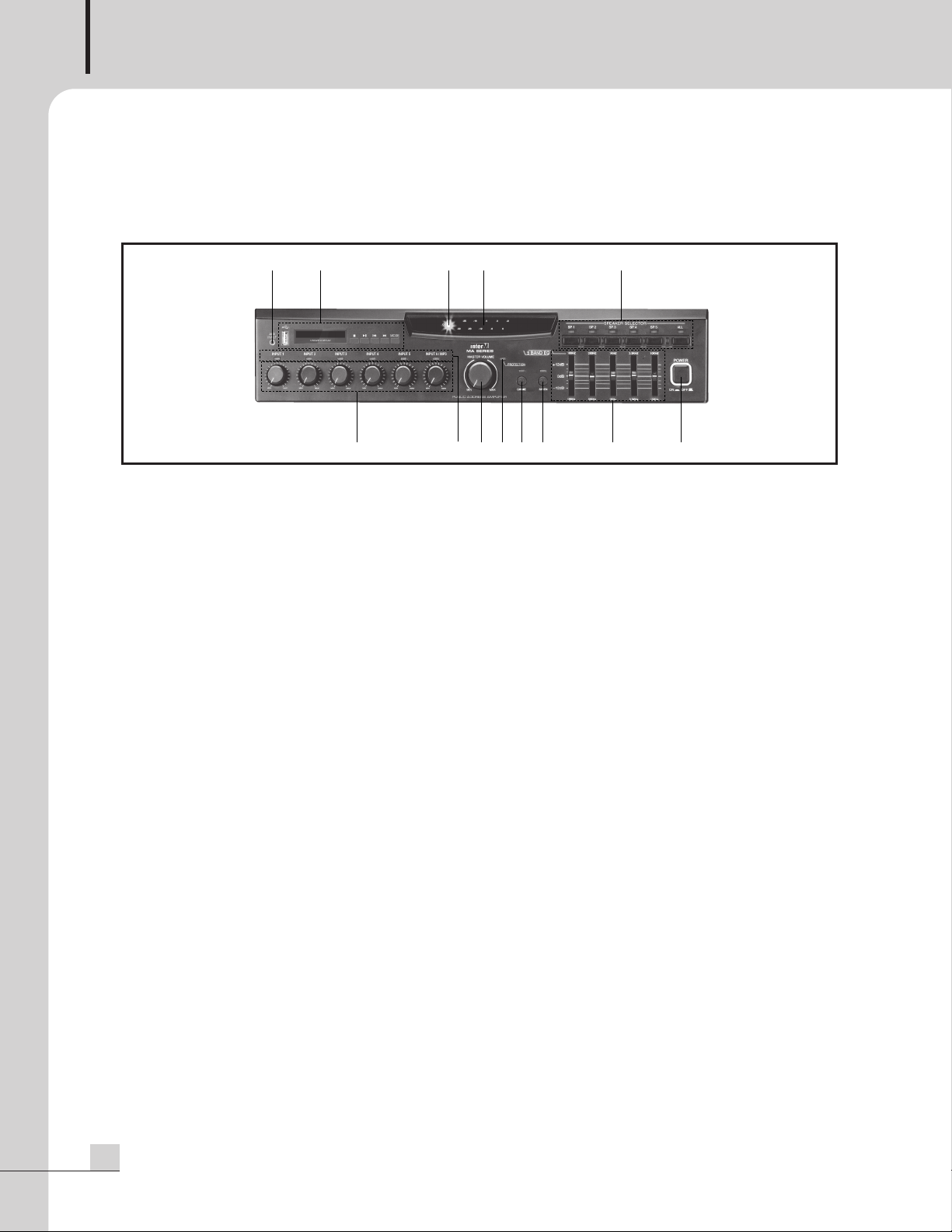
UBLIC ADDRESS AMPLIFIER
13 12
123
11
5 6 7 84
10 9
P
Front Panel
Front Panel
1. INPUT 1~6 VOLUME
These knobs provide continuous control of the volume of INPUT 1~6.
※ Volumes of USB-MP3 and AUX can be adjusted through input 6 Volume.
2. INPUT SIGNAL LED
The SIGNAL LED is lighting by input signal of each channel.
3. MASTER VOLUME
This knob provides continuous control of the overall volume of amplifier's output signal.
4. PROTECTION INDICATOR
This LED indicates the state of the amplifier's protection circuitry and MUTE function.
When the protection LED is on (illuminated), the protection circuitry is active, indicating that the unit
is not operating normally.
5. CHIME SWITCH / LED
Pressing this switch will activates the four-tone chime circuitry.
6. SIREN SWITCH / LED
Pressing this switch will activates the siren circuitry.
Pressing it a second will gradually lower the siren signal, turning it off completely after apprximately 2.5 seconds
7. GRAPHIC EQUALIZER
Each slider controls the cut (decreased gain) or boost (increased gain) for its associated frequency band.
The middle position indicates flat response (no cut or boost).
Moving the slider upwards increases that frequency's gain, while moving it down decreases the level
of that frequency.
8. POWER SWITCH (PUSH TYPE)
Pressing the power switch turns the unit on. Pressing it again turns off.
※ This switch makes up that one pole be cut off when power is off.
4
MA-206U/212U/224U
Page 7

PUBLIC ADDRESS AMPLIFIER
11 22 33 44 55 66
Play / Stop / Pause display
Display the time of sound source currently played
Display the number of sound source currently played
Display the folder currently played
Display the current
play mode
Display the title of sound source currently played
/yalP
ehtyalpsiD
desuaP/potS/
dnuosfoemite
yalpsid
nerrucecruosd
deyalpyltn
htyalpsiD
osforebmune
ucecruosdnuo
deyalpyltn
e
r
ru
yalpsiD
rrucredl
o
f
ehty
deyalpyltner
tehtyalpsiD
sdnuosfoeltit
yltnerrucecruo
deyalpy
psiD
edomyalp
n
e
r
rucehtyalp
t
9. SPEAKER SELECTOR / LED
hese switches are used to select output to any combination of up to five individual speakers.
T
10. OUTPUT LEVEL INDICATOR
This indicates the main output signal level relative to the rated power output which is marked as 0dB.
11. POWER INDICATOR
When the power switch is ON, the indicator will be it.
12. USB-MP3 MODULE
1) USB INPUT TERMINAL
It is a terminal connecting USB memory.
Caution : only FAT16, FAT32 format is supported (NTFS, exFAT, EXT2/3/4 formats are not supported.)
※ If USB memory is removed during plays, it may cause malfunction.
2) OLED DISPLAY
MA-206U/212U/224U
5
Page 8

UBLIC ADDRESS AMPLIFIER
P
3) ■ (STOP) BUTTON
t is used when stopping during plays.
I
4) ▶▶/ II(PLAY or PAUSE) BUTTON
Push it to play and push again to pause.
5) I◀◀, ▶▶I (PREVIOUS, NEXT) BUTTON
If it is pushed shortly, it skips one song.
If it is pushed for 2 seconds, it performs rewind or fast forward.
6) MODE BUTTON
If it is pushed shortly, following play modes will be set
play one song repeat one song play all repeat all random play
※ If it is pushed for 2 seconds, folder will be moved in orders
13. AUX INPUT TERMINAL
BGM input is available by connecting audio source device which has 3.5mm output terminal.
6
MA-206U/212U/224U
Page 9

Rear Panel
TEL IN
MUTE
TEL IN
VOL
13 12
1 2 3 4 5 6 7 8 9
11 10
Rear Panel
PUBLIC ADDRESS AMPLIFIER
1. AC POWER INLET
Connect this product to an appropriate AC power source using the supplied Universal AC Power Cord.
2. EXT CHIME TERMINAL
When these two terminals are shorted, the four-tone chime circuitry is activated.
3. EXT MUTE TERMINAL
When these two terminal are shorted, the output signal is blocked and the protection indicator
on the front panel is turned on.
4. VCA (VOLTAGE CONTROLLED AMPLIFIER) TERMINAL
The VCA allows remote adjustment of the post-master volume signals.
When performing the remote volume control, adjust the master volume control in advance noting
that its setting limits the maximum signal level adjustable with the volume control. Be sure to avoid turning
fully down the master volume control.
REMOTE VOLUME
10K
Ω
5. TEL IN TERMINAL
These terminals are provided for connection with a telephone exchange system for paging purposes.
※ NOTE : When the telephone input is active, all other input signal except AMP IN is able to muted.
MA-206U/212U/224U
7
Page 10

UBLIC ADDRESS AMPLIFIER
P
6. TEL IN VOLUME
t is a volume which controls the volume of TEL IN. Adjust the volume for your preference.
I
7. TEL IN MUTE VOLUME
This is able to control the mute level of all other input signal except AMP IN when the signal is inputted
from the TEL IN terminal.
8. INPUT 1~6 JACK AND INPUT SELECTION SWITCH
INPUT 1~6 are utilized to connect various external sound source devices including MIC, CD, TUNER, etc
1) INPUT 1~3 (Balanced XLR JACK) AND INPUT SELECTION SWITCH
LINE: It can be used as LINE level signal input.
MIC: It can be used as the normal dynamic MIC input.
PHANTOM: It can be used as the condenser MIC input and DC 24V is supplied to the input terminal.
2) INPUT 4~5 (Balanced 6.3Ø Phone JACK) AND INPUT SELECTION SWITCH
LINE: It can be used as LINE level signal input.
MIC: It can be used as the normal dynamic MIC input.
3) INPUT 6 (RCA JACK)
It can be used as an extra stereo input for a stereo source such as a tape deck or CD player.
NOTE: When both inputs are used, the signal is summed and combined.
9. PRIORITY CONTROL VOLUME
The output of INPUT 3~6 are controlled by the priority control volume when the signal is inputted
to the INPUT 1~2, EXT IN, CHIME and SIREN.
10. EXT IN
This line-level input connects the unit with an external mixer for expanded input channels.
11. MIX OUT
This line-level output connects the unit with an external mixdown deck or other recording source.
12. AMP IN
This input connects an external mixer or preamp with the unit’s power amp. Inserting a plug into the
Amp In jack will disconnect all input signal from the unit’s internal mixer. Only signal from the external
source will be heard.
13. SPEAKER OUTPUT TERMINAL
This terminal is for speaker wire connection.
Connect speakers whose combined impedance is equal to or higher than the rated output impedance,
as shown below.
MA-206U15.5V/4Ω100V/167Ω
MA-212U22V/4Ω100V/83Ω
MA-224U31V/4Ω100V/42Ω
2
8
MA-206U/212U/224U
Page 11

Connecting Speakers
Connecting Speakers
Before connecting speakers to your MA-206U/212U/224U unit, be sure to disconnect the AC power cable.
Make certain that the total impedance is not less than the rated impedance indicated.
For 4Ω low impedance speakers, connect in parallel, with the positive (+) connectors to the 4Ω terminal
and the negative (-) connectors to the COM terminal.
PUBLIC ADDRESS AMPLIFIER
For high impedance systems, connect with matching transformer as the following Figure. Be certain that
the total impedance does not equal less than the rated impedance.
MA-206U/212U/224U
9
Page 12

UBLIC ADDRESS AMPLIFIER
P
Applications
Applications
10
MA-206U/212U/224U
Page 13

Block Diagram
Block Diagram
PUBLIC ADDRESS AMPLIFIER
MA-206U/212U/224U
11
Page 14

UBLIC ADDRESS AMPLIFIER
P
Specifications
Specifications
MA-206UMA-212UMA-224U
Rated Output (RMS) 60W 120W 240W
Frequency Response (SP OUT/1W output) 80Hz - 15kHz
Total Harmonic Distortion
(T.H.D @ Rated output, 1kHz)
Signal to Noise Ratio (S/N @ Rated output) Better than 78dB
Graphic Equalizer
(100Hz,330Hz,1kHz,3.3kHz,10kHz)
Input Sensitivity / Impedance
MIC -50dBu / 2kΩ
Input 1~5
LINE -10dBu / 2kΩ
Input 6 -10dBu / 10kΩ
Tel in 0dBu / 10kΩ
Ext in 0dBu / 20kΩ
Amp in 0dBu / 47kΩ
Mix out / Impedance 0dBu / 10kΩ
LOW-Z 15.5V / 4Ω22V / 4Ω31V / 4Ω
Speaker out / Impedance
HIGH-Z 100V / 167Ω100V / 83Ω100V / 42Ω
Operating Temperature -10℃~ +40℃
Less than 0.5%
±12dB
Power Source 220–240VAC; 50/60Hz
Power Consumption 38W 50W 75W
Weight (SET) 5.4kg/11.9lb 6.7kg/14.8lb 8.0kg/17.6lb
Dimension (SET) 420(W) x 88(H) x 328(D)mm/16.5(W)x3.5(H)x12.9(D)in
※
Specifications and design subject to change without notice.
※
Remark: 1. All specifications are measured with AES-17 filter.
2. This system is used digital Amplifier (PWM Modulation) so the PWM leakage signal will
appear to output terminal, but it doesn’t matter. You can’t hear the PWM leakage sound
because of PWM frequencies is very higher than Audio frequencies.
12
MA-206U/212U/224U
Page 15

* Dimensions
328
420
88
PUBLIC ADDRESS AMPLIFIER
3
MA-206U/212U/224U
13
Page 16

UBLIC ADDRESS AMPLIFIER
P
Service
Service
Procedures
Take steps to insure the problem is not related to operator error or other products within the system. Information
provided in the troubleshooting portion of this manual may help with this process. Once it is certain that the
problem is related to the product contact your warranty provider as described in the warranty section of this
manual.
Schematic
A Schematic is available by contacting your warranty provider.
Parts List
A Parts List is available by contacting your warranty provider.
Variations and Options
Variations and Options
Variations
Products supplied through legitimate sources are compatible with local AC power requirements.
Options
No optional items are available for this product.
Warranty
Warranty
Warranty terms and conditions vary by country and may not be the same for all products. Terms and conditions
of warranty for a given product may be determined first by locating the appropriate country which the product
was purchased in, then by locating the product type.
To obtain specific warranty information and available service locations contact Inter-M directly or the authorized
Inter-M Distributor for your specific country or region.
14
MA-206U/212U/224U
Page 17

PUBLIC ADDRESS POWER AMPLIFIER
MA-224
3
Page 18

NOTE
2
CD-6208
Page 19

CD-6208
3
Page 20

Inter-M, Ltd. (Korea) began operations in 1983.
Since then, Inter-M has grown to become one of the largest manufacturers
of professional audio and commercial sound electronics equipment in the world.
Inter-M has gained worldwide recognition for its own branded products,
as well as private label manufacturing of electronics sold under other names (OEM).
The company is no longer just a Korean company, but rather a global company
that is truly international in scope, with factories and offices in Korea and China,
and sales and marketing operations located in Japan, Europe, and the U.S.A.
With more than 850 employees around the globe,
Inter-M is well-poised for further growth and expansion.
Inter-M Americas, INC.
13875 ARTESIA BLVD. CERRITOS, CA 90703 USA
TEL : +1-562-921-0313, FAX : +1-562-921-0370
Home Page : http://www.inter-m.net, E-mail : info@inter-m.net
Inter-M Corporation
SEOUL OFFICE:653-5 BANGHAK-DONG, DOBONG-GU, SEOUL, KOREA
TEL : +82-2-2289-8140~8, FAX : +82-2-2289-8149
Home Page : http://www.inter-m.com, E-mail : overseas@inter-m.com
MADE IN KOREA
June 2013 132307
 Loading...