

Page 1

OPERATING MANUAL
POWER
AMPLIFIER
M-500/700/1000
Page 2
11
UNPACKING AND INSTALLATION
Although it is neither complicated to install nor difficult to operate your power Amplifier, a few
minutes of your time is required to read this manual for a properly wired installation and becoming
familiar with its many features and how to use them. Please take a great care in unpacking your set
and do not discard the carton and other packing necessary to return your set for when moving your
set and are required if it ever becomes necessary to return your set for service. Never place the unit
near radiators, in front of heating vents, to direct sun light, in excessive humid or dusty location to
avoid early damage and for your years of quality use. Connect your complementary components as
illustrated in the following page.
RISK OF ELECTRIC SHOCK
DO NOT OPEN
CAUTION
CAUTION: TO REDUCE THE RISK OF ELECTRIC SHOCK.
DO NOT REMOVE COVER (OR BACK).
NO USER-SERVICEABLE PARTS INSIDE.
REFER SERVICING TO QUALIFIED SERVICE PERSONNEL.
WARNING
To prevent fire or shock hazard, do not
expose the unit to rain or moisture.
This symbol is intended to alert the user to the
presence of uninsulated “dangerous voltage”
within the product’s enclosure that may be of
sufficient magnitude to constitute a risk of electric
shock to persons.
This symbol is intended to alert the user to the
presence of important operation and maintenancy (servicing) instructions in the literature
accompanying the appliance.
Caution: To prevent electric shock do not use this (polarized) plug
with an extension cord, receptacle or other outlet unless
the blades can be fully inserted to prevent blade exposture.
Attentions: Pour prévenir les chocs électriques ne pas utilizer cette
fiche polarisée avec un prolongateur, une prise de
courant on une autre sortie de courant, sauf si les
lames peuvent étre insérées à fond sans en laisser
aucune partie à découvert.
Page 3

22
FEATURES
• SUBSTANTIAL PROTECTION CIRCUITRY
To insure stability and reliability against over current and overheating extra protection circuitry is
provided. In addition, turn on delay and DC detection circuitry is provided to protect the loudspeaker.
• BRIDGED MONO FUNCTION
These stereo amplifiers can be used for monoral powerful sound by selecting the mode switch.
• VARIOUS DISPLAY
To confirm the operating status, LED displays of protection, clip, and signals are provided on front
panel.
• COMPACT SIZE
For valuable saving in rack space and slim exterior view, these amplifier is designed within
compact size.
• SOFT-START SYSTEM
To prevent inrush current when turn on the amplifier, soft-start circuit is provided on primary power
lines.
Page 4
33
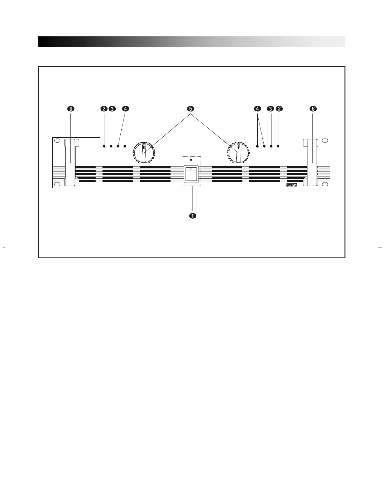
FRONT PANEL CONTROLS
1. POWER SWITCH AND INDICA TOR
The power switch is used to turn on and off the AC main power.
The power indicator lights up when the amplifier is powered ON.
2. PROTECTION INDICA TOR
This red LED indicator lights up for approximately six seconds when the amplifier is powered
ON, indicating that the soft-start protection system is working. No sound is output during softstart up. If one of the protection systems is activated during normal use, this indicator lights up
and no sound is output. The speaker system is actually disconnected from the amplifier outputs
when this indicator lights up. The protection systems are activated when overheating occurs or a
DC voltage is present at the amplifier outputs. If the problem is corrected, the protection systems
deactivate automatically , this indicator goes out, and normal amplifier operation is resumed.
3. CLIP INDICA TORS
CLIP indicator on each channel illuminates when distortion reaches or exceeds approximately
0.1%, indicating that the amplifier is being driven by excessively high inputs.
4. OUTPUT LEVEL INDICA TORS
Output level indicating LEDs indicate the output level of this amplifiers. These LEDs illuminate
when the outputs are –40dB and –20dB of rated power.
5. INPUT ATTENUATORS
Separate level controls are provided for channel one and channel two input, clockwise rotation
of the controls increase level. These are 21-step detented input signal attenuators.
6. HANDLES
You can handle this amplifier easily by using these handles.
10111213141618212723456789
1112131416182127801001234567890
0
CHANNEL1
PROT
CLIP
-20dB
-40dB
10111213141618212723456789
1112131416182127801001234567890
0
CHANNEL 2
PROT
CLIP
-20dB
-40dB
POWER
POWER AMPLIFIER
1000
M
Page 5

44
REAR PANEL CONTROLS
1. INPUT TERMINALS (CHANNEL 1, 2)
Input connectors are provided both balanced combination jacks.
Channel 1 input terminal is used in Bridge mode and parallel mode.
• XLR-TYPE CONNECTOR
They are wired pin 1-ground, pin 2-hot (+), and pin 3 cold (–).
• PHONE JACK
They are wired tip-hot (+), ring-cold (–), and sleeve-ground.
10A/250V
PUSH TO RESET
~AC INPUT
230V 50Hz, 770W
OUTPUT
BRIDGED
(8Ω~16Ω)
BRIDGED
PARALLEL
STEREO
INPUT
BALANCED
0dBm
CH 2
TRS
BALANCED
•TIP=HOT
•RING=COLD
•SLEEVE=GND
XLR
BALANCED
•3=COLD
•2=HOT
•1=GND
PUSH
BALANCED
0dBm
(4Ω~8Ω)
(4Ω~8Ω)
(4Ω~8Ω)
(4Ω~8Ω)
PUSH
CH 1
CH 2
CH 1
213
HOT
GROUND
COLD
PUSH
213
HOT
GROUND
COLD
COLD
GROUND
HOT
XLR MALE COMBINATION
FOR LINK
FOR INPUT
Page 6

STEREO MODE, BRIDGED MODE AND PARALLEL MODE
55
2. OUTPUT TERMINALS
Output terminals are dual five-way binding posts and speaker connectors. Do not parallel the two
outputs of each channel by connecting them (together, or parallel them) with any other amplifier output.
* When speakers are connected through speaker, please make sure correct connection of each
pin, and refer speaker pin number.
• STEREO MODE • BRIDGED MODE
The minimum impedance for the connected speaker system is specified in “Speaker Impenance” on page 6.
3. CIRCUIT BREAKER
When the circuit breaker is cut, push to reset again. In case of occurring trouble to the set by
means of overload or error, circuit breaker will protect the set from trouble by breaking AC power
source.
4. AC POWER CORD
Plug this AC input cord into AC outlet.
5. MODE SELECTOR
Bridged mono or parallel operation are easily accessed by the slide switch. The input is applied
channel one only the corresponding front panel control is used to set the level, please refer
bridged mono operation or parallel operation.
6. FANS
The fans should be kept free of all obstructions and be accessible to cool fresh air when
1-1+2+2-AMP OUTPUT CH1, CH2
NOT CONNECTED
OUTPUT
BRIDGED
(8Ω~16Ω)
(4Ω~8Ω)
(4Ω~8Ω)
(4Ω~8Ω)
(4Ω~8Ω)
CH 2
CH 1
OUTPUT
BRIDGED
(8Ω~16Ω)
(4Ω~8Ω)
(4Ω~8Ω)
(4Ω~8Ω)
(4Ω~8Ω)
CH 2
CH 1
1-1+2+2-MONO(BTL)
NOT CONNECTED
CH1 OR CH2
• STEREO MODE
In this mode, channels 1 and 2 operate independently (typical stereo amplifier). Channel 1 input
signal feeds channel 1 power amp, and channel 2 input signal feeds channel 2 power amp. In this
mode, the minimum speaker impedance per channel is 4Ω.
• BRIDGED MODE
In this mode, channels 1 and 2 are bridged together and work as one mono amplifier. In this
mode, the minimum speaker impedance is 8Ω.
• PARALLEL MODE
In this mode, channels 1 and 2 are operate two mono amplifier. In this mode channel 1 input signal
feeds channel 1 and channel 2 power amp, the minimum speaker impedance per channel is 4Ω.
Page 7

66
SPEAKER IMPEDANCE
M-500/M-700/M-1000 series amplifier has three operating modes: Stereo, Bridged and Parallel and
allows you to connect multiple speaker systems in parallel. Therefore, the minimum speaker impenance various depending on the combination of these speakers. Be sure that the speaker
impedance falls below the specified impedance.
The figures below show the examples of connection is Stereo mode and Bridged mode, and
speaker systems connected in parallel in Stereo mode, and the respective minimum impedance.
STEREO MODE CONNECTIONS BRIDGED MODE CONNECTIONS
OUTPUT
BRIDGED
(8Ω~16Ω)
BRIDGED
PARALLEL
STEREO
TRS
BALANCED
•TIP=HOT
•RING=COLD
•SLEEVE=GND
XLR
BALANCED
•3=COLD
•2=HOT
•1=GND
BALANCED
0dBm
(4Ω~8Ω)
(4Ω~8Ω)
(4Ω~8Ω)
(4Ω~8Ω)
(4Ω min)
(4Ω min)
OUTPUT
BRIDGED
(8Ω~16Ω)
BRIDGED
PARALLEL
STEREO
TRS
BALANCED
•TIP=HOT
•RING=COLD
•SLEEVE=GND
XLR
BALANCED
•3=COLD
•2=HOT
•1=GND
BALANCED
0dBm
(4Ω~8Ω)
(4Ω~8Ω)
(4Ω~8Ω)
(4Ω~8Ω)
(8Ω min)
OUTPUT
BRIDGED
(8Ω~16Ω)
BRIDGED
PARALLEL
STEREO
TRS
BALANCED
•TIP=HOT
•RING=COLD
•SLEEVE=GND
XLR
BALANCED
•3=COLD
•2=HOT
•1=GND
BALANCED
0dBm
(4Ω~8Ω)
(4Ω~8Ω)
(4Ω~8Ω)
(4Ω~8Ω)
(4Ω min)
(4Ω min)
OUTPUT
BRIDGED
PARALLEL
STEREO
TRS
BALANCED
•TIP=HOT
•RING=COLD
•SLEEVE=GND
XLR
BALANCED
•3=COLD
•2=HOT
•1=GND
BALANCED
0dBm
(4Ω~8Ω)
(4Ω~8Ω)
(4Ω~8Ω)
(4Ω~8Ω)
(8Ω min)
(8Ω min)
(8Ω min)
(8Ω min)
BRIDGED
(8Ω~16Ω)
OUTPUT
BRIDGED
(8Ω~16Ω)
BRIDGED
PARALLEL
STEREO
TRS
BALANCED
•TIP=HOT
•RING=COLD
•SLEEVE=GND
XLR
BALANCED
•3=COLD
•2=HOT
•1=GND
BALANCED
0dBm
(4Ω~8Ω)
(4Ω~8Ω)
(4Ω~8Ω)
(4Ω~8Ω)
(8Ω min)
OUTPUT
BRIDGED
(8Ω~16Ω)
BRIDGED
PARALLEL
STEREO
TRS
BALANCED
•TIP=HOT
•RING=COLD
•SLEEVE=GND
XLR
BALANCED
•3=COLD
•2=HOT
•1=GND
BALANCED
0dBm
(4Ω~8Ω)
(4Ω~8Ω)
(4Ω~8Ω)
(4Ω~8Ω)
(8Ω min)
Page 8

77
CAUTION FOR SPEAKER CONNECTION
1. Turn off the POWER switch.
2. After removing approx. 10 mm of insulation from the ends of the speaker cables, pass the bare
ends of the speaker wires through the holes in the corresponding speaker terminals and tighten
the terminals to securely clamp the wires.
Refer to page 4 for speaker porality .
At this time make sure that the bare ends of the speaker cables do not extend from the terminals
in such a way that they touch the chassis.
• SPEAKER FUSE
The output capacity of your amplifier is very high: 500W+500W (4Ω) in stereo and 1000W (8 Ω) in
monaural on the M-1000: 350W+350W (4Ω) in stereo and 700W (8Ω) in monaural on the M-700:
250W+250W (4Ω) in stereo and 500W (8Ω) in monaural on the M-500. Be sure to use a speaker
system that has sufficient input capacity.
If the input capacity of your speaker system is lower than the rated output of the power amplifier,
you can protect your speakers by connecting a fuse serially between the speaker and amplifier as
shown below.
10mm
POWER AMPLIFIER
SPEAKER SYSTEM
FUSE
Wire should not
touch the chassis
Page 9

88
Use the following formula to determine the fuse capacity according to the speaker’s input
capacity.
Po = I2R I =
P0 [W]: Speaker’s continuous input capacity (noise or RMS)
R [Ω] : Speaker’s nominal impedance
I [A] : Required fuse capacity
ex.) Speaker’s continuous input capacity: 100W
Speaker’s impedance: 8Ω
I = = 3.5
In this example, the required fuse capacity is calculated as 3.5 [A].
• SPEAKER CABLE
If you use a long speaker cable, use as thick a cable as possible to prevent deterioration of the
damping factor or power loss inside the cable. Even the thickest cable can be used for the
speaker terminal of this unit.
PORTABLE RACK MOUNTING
The amplifier intakes cool air through the front panel and exhausts warm air out the rear panel.
When mounting amplifiers in a portable rack, make sure the rear panel is completely open for
ventilation.
10A/250V
PUSH TO RESET
OUTPUT
BRIDGE
(8Ω~16Ω)
BRIDGED
PARALLEL
STEREO
INPUT
BALANCED
0dBm
PUSH
(4Ω~8Ω)
(4Ω~8Ω)
(4Ω~8Ω)
(4Ω~8Ω)
PUSH
CH 2
CH 1
CH 2
CH 1
(Side View)
Front
Air exhaust
Air intake
(Rear View)
Completely open
Po
R
100
8
Page 10

99
POSITIONING THE HOUSED AMPLIFIER
Place the case so that the ventilation airflow paths are not blocked.
TROUBLESHOOTING
The following table lists the main causes of abnormal operation and the corrective measures
required, as well as the protective circuit operation in each case.
Indicator Probable Cause Remedy Protection Circuit
CLIP indicator
lights.
–40dB indicator
lights only.
There is a short at a
speaker terminal,
amplifier terminal, or
wire.
The amplifier load is
excessive.
DC voltage of +/–2V
or greater was generated
in the power amplifier’s
output circuit.
Consult your dealer. The relay operates to
protect the speaker
system.
The heat sink
temperature has
exceeded 100˚C.
Locate and correct the
cause of the short.
Use a speaker system
with an impedance of at
least 4Ω (stereo) or 8Ω
(bridge).
Check the amplifier
ventilation conditions
and take appropriate
measures to improve
airflow around the
amplifier.
The PC limiter circuit
operates to protect the
power transistors.
Same as above.
The thermal protection
circuit operates to
protect the power
transistors.
PROTECTION
indicator lights.
Front
Front
Less than 10 cm
NO NO
Page 11

1100
SPECIFICATIONS
M-500 M-700 M-1000
(Front) Power SW: Push up On/Push down Off
Attenuator: 21-position dB calibrated
(Rear) Mode Sw: Bridge=BTL/STEREO/PARALLEL
UL & Canadian Model: 120V, 60Hz
General Model: 230V, 50Hz
British Model: 240V, 50Hz
420W 520W 770W
12kg/26.4lb 15kg/33lb 17kg/37.5lb
482(W) x 88(H) x 369(D) mm/19(W)x3.5(H)x14.5(D)in
Input XLR-3-31 type + 1/4" Phone (balanced), XLR
Output5-Way binding posts x 2, Speakon Terminal x 2
Power Output Level
f=1KHz, THD+N≤0.05% (Typical)
STEREO RL=8Ω
RL=4Ω
BRIDGED RL=8Ω
One Channel Driven
f=1KHz THD+N≤0.05% RL=8Ω
Frequency Response RL=8Ω, P.=1W
Power Bandwidth Half Power, THD+N≤0.1%
STEREO RL=8Ω
Total Harmonic Distortion (THD+N)
f=20Hz~20KHz, Half Power
STEREO RL=8Ω
RL=4Ω
BRIDGED RL=8Ω
Channel Separation Half Power RL=8Ω,
f=1KHz, ATT. max. Input 600Ω shunt
Residual Noise (DIN Audio Filter)
Signal-to-Noise Ratio DIN Audio,
Input 600Ω Shunt
Damping Factor RL=8Ω, f=1KHz
Slew Rate 8Ω Full Swing STEREO
BRIDGED
Sensitivity (ATT max.)
Rated Power into 4Ω 1KHz
Voltage Gain (ATT max.) 4Ω 1KHz
Input Impedance (ATT max.)
Indicators
Protection
PC Limiter
Fan Circuit
Controls
Power Source
Power Consumption
Weight
Dimensions
Connectors
130W+130W 220W+220W 330W+330W
250W+250W 350W+350W 520W+520W
500W 700W 1000W
150W 250W 350W
0dB+0.5, –1.5dB: f=DC~55KHz
10Hz~70KHz
≤ 0.05%
≤ 0.07%
≤ 0.07%
≥ 80dB
≤ –70dB: ATT min.
≥100dB
≥150
±40V/µs
0dBm
32dB 33.5dB 35dB
≥ 20KΩ (Balance/Unbalance)
Power (Red)
Protection (Mute) x 2 (Red)
Clip x 2 (Orange)
Signal x 4 (Green)
Power SW ON/OFF muting
Heatsink Temp ≥ 100˚C (212˚F)
RL < 2Ω
–50˚C (122˚F)–60˚C (140˚F)–
Low-Speed – Variable – Hi-Speed
0dB=0.775 Vrms, Half Power=1/2 Power Output Level (Rated Power)
* Using reactive 2Ω speakers at high power levels may cause overheating, excessive power consumption, and shutdowns.
Please note that below 2Ω the PC limiter will work. Before using 2Ω speakers in a real application, test the system completely.
Page 12

MADE IN KOREA
 Loading...