

Page 1

Operation Manual
Professional Power Amplifier
L800/1400/1800/2400/3000
Page 2

PROFESSIONAL POWER AMPLIFIER
English
Contents
Contents
Welcome
Warning.........................................................................................................................................1
Unpacking......................................................................................................................................2
Short Form Instructions.....................................................................................................................2
Installation
Environment....................................................................................................................................3
Important Safety Instructions.............................................................................................................3
Description.......................................................................................................................................4
Features............................................................................................................................................4
Accessories.....................................................................................................................................4
Front Panel ......................................................................................................................................5
Rear Panel .......................................................................................................................................6
Applications
Stereo Installation ...........................................................................................................................8
Parallel Installation ..........................................................................................................................8
Bridge Mono Installation ..................................................................................................................9
Linked Installation............................................................................................................................9
Connections..................................................................................................................................10
Block Diagrams.............................................................................................................................11
Specifications ................................................................................................................................13
Service
Procedures....................................................................................................................................14
Schematic.....................................................................................................................................14
Parts List .......................................................................................................................................14
Variations and Options...............................................................................................................14
Warranty .......................................................................................................................................14
Page 3
PROFESSIONAL POWER AMPLIFIER
1
L800/1400/1800/2400/3000
English
Welcome
Welcome
A personal welcome to you from the management and employees of Inter-M
All of the co-workers here at Inter-M are dedicated to providing excellent products with inherently good value,
and we are delighted you have purchased one of our products.
We sincerely trust this product will provide years of satisfactory service, but if anything is not to your complete
satisfaction, we will endeavor to make things right.
Welcome to Inter-M, and thank you for becoming part of our worldwide extended family!
* It can be heated up if you use this product in closed box or ill-ventilated place.
RISK OF ELECTRIC SHOCK
DO NOT OPEN
CAUTION
CAUTION: TO REDUCE THE RISK OF ELECTRIC SHOCK.
DO NOT REMOVE COVER (OR BACK).
NO USER-SERVICEABLE PARTS INSIDE.
REFER SERVICING TO QUALIFIED SERVICE PERSONNEL.
WARNING
To prevent fire or shock hazard, do not
expose the unit to rain or moisture.
*Do not install this equipment in a confined space such as a book case or similar unit.
*The apparatus shall not be exposed to dripping or splashing and no objects filled with liquids, such vases, shall be placed on the apparatus.
*Worded: “WARNING FOR YOUR PROTECTION PLEASE READ THE FOLLOWING-WATER AND MOISTURE: Unit should not be used near
water(e.g. near a bathtub, washbowl, kitchen sink, laundry tub, in a wet basement, or near a swimming pool, etc). Care should be taken so than
objects do not fall and liquids are not spilled into the enclosure through openings.”
Service Instructions
*Worded: "Caution: These servicing instructions are for use by qualified service personnel only. To reduce the risk of electric shock, do not
perform any servicing other than that contained in the operating instructions unless you are qualified to do so."
*Location: Instruction Manual.
NOTE : This equipment has been tested and found to comply with the limits for a Class A digital device, pursuant to Part 15 of the FCC Rules. These
limits are designed to provide reasonable protection against harmful interference when the equipment is operated in a commercial
environment. This equipment generates, uses, and can radiate radio frequency energy and, if not installed and used in accordance with the
instruction manual, may cause harmful interference to radio communications. Operation of this equipment in a residential area is likely to cause
harmful interference in which case the user will be required to correct the interference at his own expense.
This symbol is intended to alert the user to the
presence of uninsulated “dangerous voltage” within
the product’s enclosure that may be of sufficient
magnitude to constitute a risk of electric shock to
persons.
This symbol is intended to alert the user to the
presence of important operation and maintenance
(servicing) instructions in the literature accompanying
the appliance.
Caution: To prevent electric shock do not use this (polarized) plug with
an extension cord, receptacle or other outlet unless the blades
can be fully inserted to prevent blade exposure.
Attentions: Pour prévenir les chocs électriques ne pas utiliser cette
fiche polarisée avec un prolongateur, une prise de courant
on une autre sortie de courant, sauf si les lames peuvent
étre insérées à fond sans en laisser aucune partie à
découvert.
Page 4

PROFESSIONAL POWER AMPLIFIER
2
L800/1400/1800/2400/3000
English
Unpacking
Please take a few minutes to read this manual to familiarize yourself with important information regarding
installation, product features, and operation.
As with most electronic devices, ORIGINAL PACKAGING (OR EQUAL) IS REQUIRED in the unlikely event that
the product needs to be returned for servicing.
Short Form Instructions
1. Do not connect the AC power until step 6. The ac mains POWER switch should be in the OFF position.
2. Adjust both of the LEVEL controls to the fully attenuated position (turn fully counter-clockwise).
3. Connect an appropriate line level input signal to either the balanced XLR or the balanced 1/4” TRS (TipRing-Sleeve) connector marked INPUTS.
4. Move the MODE selector to the desired position. The Stereo position is the most common.
5. Connect the OUTPUTS to the speaker load according to the mode of operation determined in the previous
step.
6. With the ac mains POWER switch in the OFF position, plug in the supplied Universal AC power cord to the
product and connect to an appropriate AC source.
7. Depress the ac mains POWER switch to the ON position. The indicator within the power switch will
illuminate.
8. The product is ready for operation. Slowly increase the LEVEL control to the desired operating level. Avoid
illuminating the PEAK indicator and do not apply too much power to the speakers.
9. Operate the product and the system in a manner which DOES NOT illuminate the PEAK warning indicator.
Page 5

PROFESSIONAL POWER AMPLIFIER
3
L800/1400/1800/2400/3000
English
Installation
Installation
Environment
Never place this product in an environment which could alter its performance or reduce its service life. Such
environments usually include high levels of heat, dust, moisture, and vibration.
Important Safety Instructions
1. Read these instructions.
2. Keep these instructions.
3. Heed all warnings.
4. Follow all instructions.
5. Do not use this apparatus near water.
6. Clean only with dry cloth.
7. Do not block any ventilation openings. Install in accordance with the manufacturer’s instructions.
8. Do not install near any heat sources such as radiators, heat registers, stoves, or other apparatus (including
amplifiers) that produce heat.
9. Do not defeat the safety purpose of the polarized or grounding-type plug. A polarized plug has two blades
with one wider than the other. A grounding type plug has two blades and a third grounding prong. The wide
blade or the third prong are provided for your safety. If the provided plug does not fit into your outlet, consult
an electrician for replacement of the obsolete outlet.
10. Protect the power cord from being walked on or pinched particularly at plugs, convenience receptacles, and
the point where they exit from the apparatus.
11. Only use attachments/accessories specified by the manufacturer.
12. Use only with the cart, stand, tripod, bracket, or table specified by the manufacturer, or sold with the apparatus.
When a cart is used, use caution when moving the cart/apparatus combination to avoid injury from tip-over.
13. Unplug this apparatus during lightning storms or when unused for long periods of time.
14. Refer all servicing to qualified service personnel. Servicing is required when the
apparatus has been damaged in any way, such as power-supply cord or plug is
damaged, liquid has been spilled or objects have fallen into the apparatus, the
apparatus has been exposed to rain or moisture, does not operate normally, or has
been dropped.
S3125A
S3125A
Page 6

PROFESSIONAL POWER AMPLIFIER
4
L800/1400/1800/2400/3000
English
Description
- L800
A 2U rack space, 2 channel amplifier capable of 800W into 4Ω load (bridged mono).
- L1400
A 2U rack space, 2 channel amplifier capable of 1400W into 4Ω load (bridged mono).
- L1800
A 2U rack space, 2 channel amplifier capable of 1800W into 4Ω load (bridged mono).
- L2400
A 2U rack space, 2 channel amplifier capable of 2400W into 4Ω load (bridged mono).
- L3000
A 2U rack space, 2 channel amplifier capable of 3000W into 4Ω load (bridged mono).
Features
- 2Ω-load stable per channel, 4Ω-load stable in bridge mono
- 2U rack space
- Selectable High Pass Filter on each channel
- Clip limiter circuitry
- Forced air cooled (front panel intake, rear panel exhaust)
- Front panel indicators for different operating modes
- Front panel indicators for output signal level, clip, protect, and power
- Rack Ears for permanent installation in a standard 19” (rack mount width) enclosure.
- Detachable AC power cord
Accessories
One detachable universal AC mains power cord is provided for use with this product.
Description
- L800
A 2U rack space, 2 channel amplifier capable of 800W into 4Ω load (bridged mono).
- L1400
A 2U rack space, 2 channel amplifier capable of 1400W into 4Ω load (bridged mono).
- L1800
A 2U rack space, 2 channel amplifier capable of 1800W into 4Ω load (bridged mono).
- L2400
A 2U rack space, 2 channel amplifier capable of 2400W into 4Ω load (bridged mono).
- L3000
A 2U rack space, 2 channel amplifier capable of 3000W into 4Ω load (bridged mono).
Features
- 2Ω - load stable per channel, 4Ω - load stable in bridge mono
- 2U rack space
- Selectable High Pass Filter on each channel
- Clip limiter circuitry
- Forced air cooled (front panel intake, rear panel exhaust)
- Front panel indicators for different operating modes
- Front panel indicators for output signal level, clip, protect, and power
- Rack Ears for permanent installation in a standard 19” (rack mount width) enclosure.
- Detachable AC power cord
Accessories
One detachable universal AC mains power cord is provided for use with this product.
Page 7
PROFESSIONAL POWER AMPLIFIER
5
L800/1400/1800/2400/3000
English
Front Panel
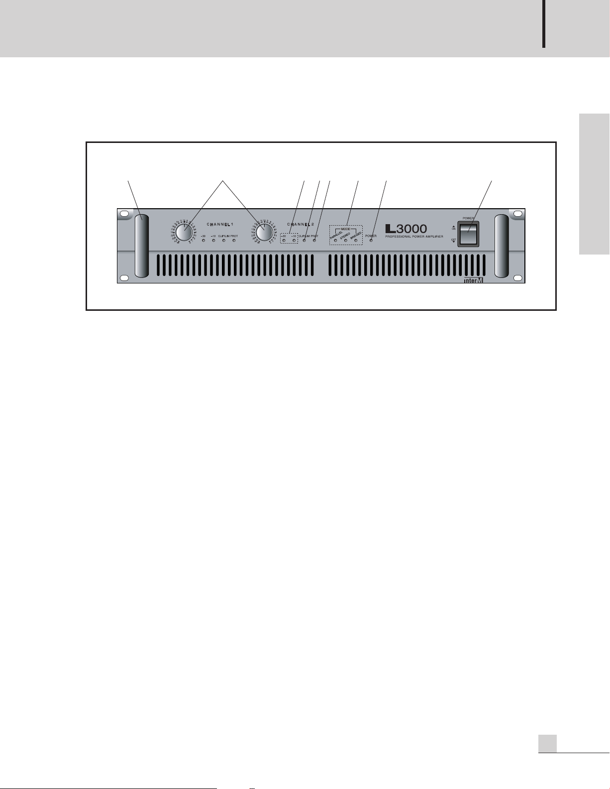
Front Panel
1. HANDLES
These are provided for easy transporting and installing into equipment enclosures or racks.
2. LEVEL CONTROL
This control adjusts the level (amplitude) of the input signal for each channel. In stereo or parallel mode the
knobs will determine the signal level independently for each channel. In the bridge mono mode channel 1 will
be turned fully to the right and channel 2 will be turned right only as needed to achieve the desired signal level.
3. LEVEL INDICATOR
These indicators should illuminate during normal operation when there is an output signal.
4. CLIP LIMITER INDICATOR
This warns of a problem when illuminated. Reduce the LEVEL of the device which supplies signal to the
amplifier or reduce the LEVEL control(s) on the amplifier. This should not be continuously illuminated during
normal operation, but may flash occasionally.
5. PROTECTION INDICATOR
This warns of a problem in the system when illuminated. Reduce the volume and look for problems. It is
possible that the amplifier is too hot or the speaker impedance is too low. This should not be illuminated
during normal operation.
6. MODE INDICATOR
This indicates the operating mode based on the position of the MODE selector switch located on the rear panel.
7. POWER INDICATOR
This confirms the amplifier is switched ON and receiving AC mains POWER when illuminated.
8. POWER SWITCH
The position of this switch determines whether the AC mains power is ON or OFF. The power-on status is
confirmed by the illuminated power indicator. Amplifiers are always the last item in a system to be turned on.
It is generally a good idea to reduce the level controls before applying AC mains power.
1234567 8
Page 8
PROFESSIONAL POWER AMPLIFIER
6
L800/1400/1800/2400/3000
English
Rear Panel
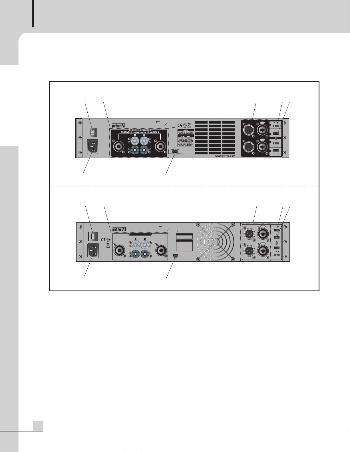
Rear Panel
1. AC INPUT
Connect this product to an appropriate AC mains power source using the supplied Universal AC Power Cord.
2. CIRCUIT BREAKER
This protects the amplifier by shutting down the power when the amplifier operates abnormally due to
overload or malfunction. Push to reset.
3. OUTPUT CONNECTORS
Binding Posts and Speakon-type connectors are provided. Bridged Mono operation requires a different
method of connecting the speaker cables than Stereo operation. Be sure than the amplifier is in the correct
mode before connecting the speaker load.
INPUT 1
INPUT 2
PUSH
PUSH
23
14
567
PUSH TO RESET
15A / 250V
TO REDUCE THE RISK
OF ELECTRIC SHOCK,
DO NOT REMOVE COVER.
NO USER SERVICEABLE
PARTS INSIDE.REFER
SERVICING TO QUALIFIED
SERVICE PERSONNEL.
CAUTION
RISQUE DE CHOC ELEC-
TRIQUE NE PAS OUVRIR.
AVIS
CLASS 2 WIRING
www.inter-m.com
MODEL NO. L3000
PROFESSIONAL POWERAMPLIFIER
RATED OUTPUT 1000W/CH @4
Ω STEREO, PARALLEL
RATED OUTPUT 2000W/CH @8
Ω BRIDGED MONO
STEREO
BRIDGED
PARALLEL
AMP MODE
BRIDGED MONOCHANNEL 2 CHANNEL 1
SPEAKER OUTPUTS
~AC INPUT
230V 50Hz, 5A
30Hz
OFF 50Hz
HPF
OFF ON
LIM
30Hz
OFF 50Hz
HPF
OFF ON
LIM
MADE IN KOREA
S
N
- L800/1400/1800/2400
- L3000
23
PUSH TO RESET
11A / 250V
~AC INPUT
230V 50Hz, 4.5A
MODEL NO. L2400
PROFESSIONAL POWER AMPLIFIER
RATED OUTPUT 750W/CH @4
S
N
MADE IN KOREA
CLASS 2 WIRING
14
567
ON
OFF
PUSH
LIM
30Hz
50Hz
OFF
HPF
INPUT 1
PUSH
LIM
ON
OFF
HPF
INPUT 2
30Hz
50Hz
OFF
Page 9

PROFESSIONAL POWER AMPLIFIER
7
L800/1400/1800/2400/3000
English
4. MODE SELECTOR SWITCH
Move this switch to select the STEREO, PARALLEL or BRIDGED MONO position as needed for the application.
The Stereo mode is most common. Channel 1 input provides signal through the amplifier to the channel 1
output. The channel 2 input provides signal through the amplifier the channel 2 output.
The Parallel mode uses the channel 1 input provides signal through the amplifier to both the channel 1 and
channel 2 outputs. No input will be supplied to channel 2 in the Parallel mode.
The Bridge Mono mode combines both channels to create one larger mono channel. Input signal applied to
channel 1 will provide signal through the amplifier to the positive terminals of Channel 1 and channel 2. Do
not connect any signal to the channel 2 input or any loads to the negative outputs.
5. BALANCED INPUT CONNECTORS
Each input channel is equipped with a special connector that will accept either a 1/4” TRS or an XLR
connector. Even though the connector is of a special design, the standard rules for wiring the input
connectors apply.
6. CLIP LIMITER SWITCH
The CLIP LIMITER reduces the internal operating level of the amplifier as necessary to insure that signal peaks
do not overdrive the amplifier, causing distortion or damage to the amplifier or loudspeakers. It is
recommended to leave this switched to the “ON” position to reduce distortion and help provide protection to
the loudspeakers.
7. HIGH PASS FILTER SWITCH
Select the switch position that is best suited for your application. The OFF position allows full frequency range
signals to reach the loudspeakers. The 30Hz position reduces the signal amplitude below 30 Hz to conserve
power and help protect the loudspeakers. The 50Hz position reduces the signal amplitude below 50 Hz to
conserve power and help protect the loudspeakers.
Page 10
PROFESSIONAL POWER AMPLIFIER
8
L800/1400/1800/2400/3000
English
Applications
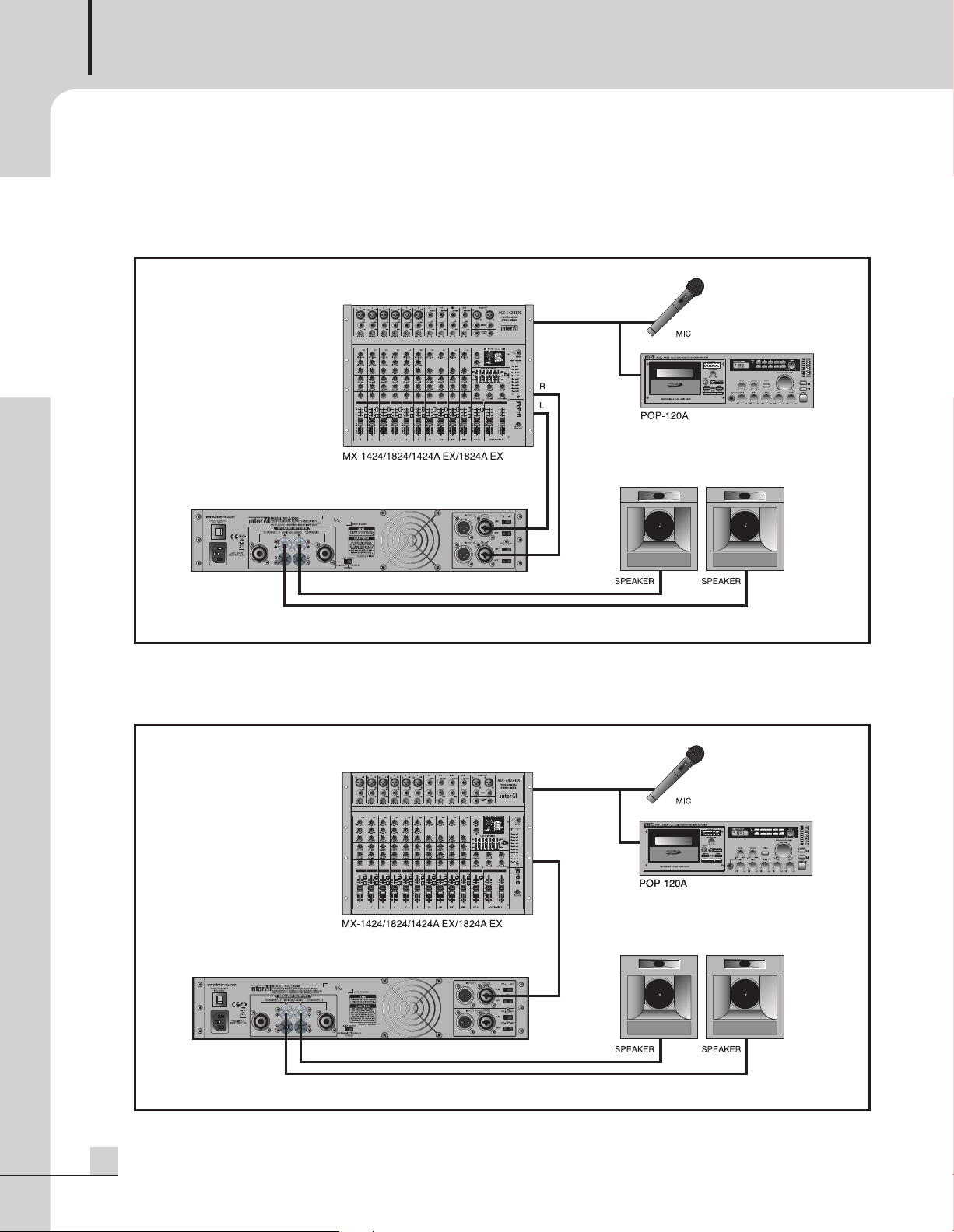
Applications
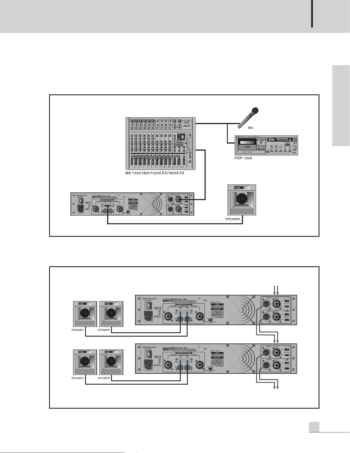
Stereo Installation
Parallel Installation
Page 11
PROFESSIONAL POWER AMPLIFIER
9
L800/1400/1800/2400/3000
English
Applications
Applications
Bridged Mono Installation
Linked Installation
Linking is possible when in Stereo/Parallel or Bridged Mono operation
Page 12
PROFESSIONAL POWER AMPLIFIER
10
L800/1400/1800/2400/3000
English
Connections
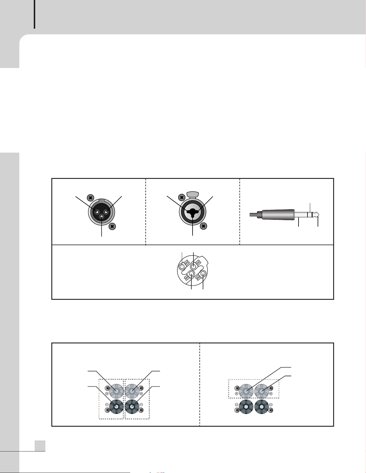
Inter-M products are wired according to professionally accepted wiring practices used throughout the world.
Balanced XLR connectors are wired as described:
Pin #1 shield
Pin #2 Positive
Pin #3 Common
Balanced 1/4” TRS connectors are wire as described:
Tip is Positive
Ring is Common
Sleeve is Shield
The combination connector is designed to accept either the XLR or the 1/4” TRS Phone Jack
Stereo operation uses the + (positive) and the – (negative) terminal from each set of channel output binding
posts. (CH1 : 1+, 1- /CH2 : 2+, 2-)
Bridged Mono uses the + (positive) terminal of both channels only. The – (negative) terminals have no
connection. Bridged Mono operation has a minimum load impedance of 4Ω.
- XLR MALE
- COMBINATION
- SPEAKON CONNECTOR
Pin set #1
Wiring Diagram
- PHONE JACK
- STEREO/PARALLEL CONNECTION - BRIDGED MONO CONNECTION
12
3
GROUND HOT
COLD
PUSH
12
3
GROUNDHOT
COLD
1- 1+
2+ 2-
GROUND HOT
COLD
POSITIVE
NEGATIVE
CH2
CH1
POSITIVE
NEGATIVE
CH2 CH1
NEGATIVE
POSITIVE
Page 13

PROFESSIONAL POWER AMPLIFIER
11
L800/1400/1800/2400/3000
English
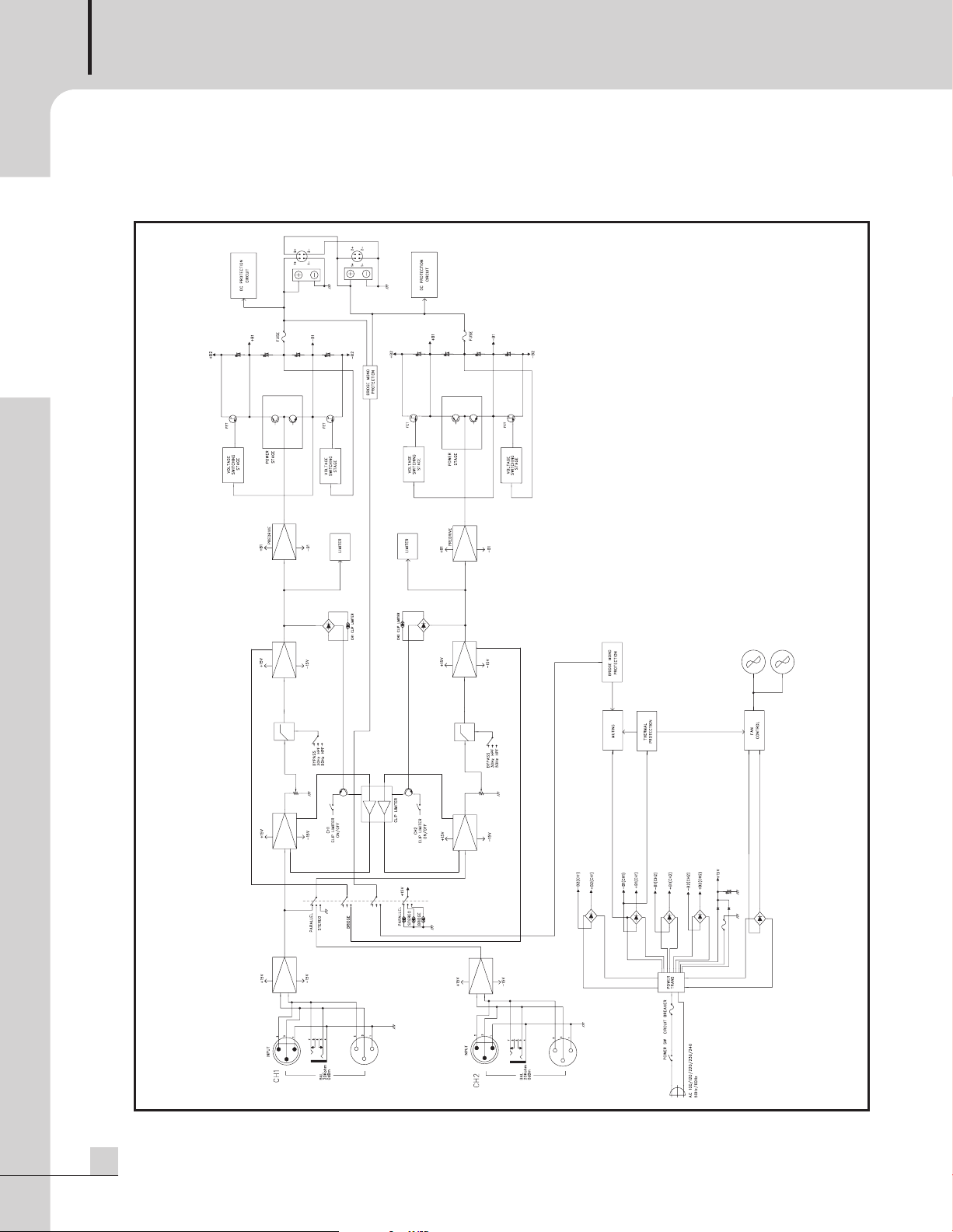
Block Diagrams
Block Diagrams
- L800/1400/1800/2400
Page 14
PROFESSIONAL POWER AMPLIFIER
12
L800/1400/1800/2400/3000
- L3000
English
Page 15
PROFESSIONAL POWER AMPLIFIER
13
L800/1400/1800/2400/3000
English
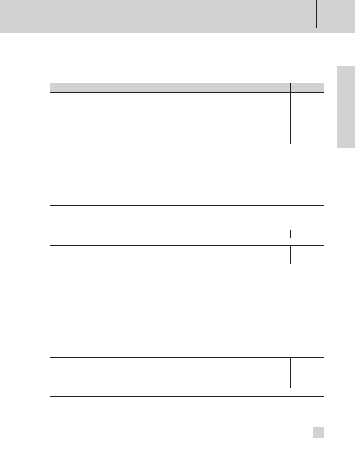
Specifications
Specifications
0dB=0.775Vrms, Half Power=1/2 Power Output Level (Rated Power)
* Specifications and design subject to change without notice.
L800 L1400 L1800 L2400 L3000
Power Output Level
STEREO 1kHz both channels driven
R
L
=8Ω @ 0.1% THD 200W 280W 360W 500W 650W
R
L
=4Ω @ 0.1% THD 300W 450W 600W 750W 1000W
R
L
=2Ω @ 0.5% THD 430W 700W 900W 1200W 1500W
BRIDGED R
L
=8Ω 1kHz @ 0.1% THD 600W 900W 1200W 1500W 2000W
R
L
=4Ω 1kHz @ 0.5% THD 800W 1400W 1800W 2400W 3000W
Frequency Response R
L
=8Ω, P=1W 20Hz~20kHz: ±0/1dB, 5Hz~70kHz: -3dB
Total Harmonic Distortion
f=20Hz~20kHz, Half Power(L800/1400)
1/10Power(L1800/2400/3000)
STEREO R
L
=8Ω & 4Ω≤0.03%
BRIDGED R
L
=8Ω≤0.03%
Channel Separation Half Power R
L
=8Ω,
f=1kHz, ATT. max. Input 600Ω Shunt
≥80dB
Residual Noise(DIN Audio Filter) ≤-85dB: ATT min.
Signal-to-Noise Ratio DIN Audio,
Input 600Ω Shunt ≥100dB
Input Sensitivity (Rated Power into 4Ω 1kHz) 2.7dBu 2.7dBu 3.5dBu 3.5dBu 3.5dBu
Damping Factor R
L
=8Ω, f=1kHz ≥400
Voltage Gain (ATT max.) 4Ω at 1kHz 30dB 32dB 33dB 34dB 38.5dB
Output Circuitry AB Class AB Class H Class H Class H Class
Input Impedance (ATT max.) ≥20kΩ (Balance/Unbalance)
Indicators Power (Blue)
Clip/Limiter (Red)
Signal (Green)
Protection (Red)
Mode Selector (Yellow)
Protection Power SW ON/OFF muting, Full Short circuit,
Thermal protection, RF protection
Fan Circuit Low-Speed - Variable - Hi-Speed
Operating Temperature -10°C ~ +40°C
Power Source 100-120VAC or 220-240VAC; 50/60Hz
(Supplied AC mains transformer depends on country requirements)
Power Consumption(1/8 POWER)
100V-120VAC Both Channel Driven R
L
=4Ω 6A 7A 8A 9A 11A
230V-240VAC Both Channel Driven R
L
=4Ω 3A 3.5A 4A 4.5A 5A
Weight
14kg/30.8lb 14.4kg/31.7lb 15kg/33lb 15.6kg/34.6lb 19.5kg/39.5lb
Dimensions 482(W) x 88(H) x 369(D)mm / 19(W) x 3.5(H) x 14.5(D)in
Connector Inputs: balanced combination connector(XLR type+1/4
TRS)
Outputs: 5-Way binding posts x 2, Speakon Terminal x 2
Page 16

PROFESSIONAL POWER AMPLIFIER
14
L800/1400/1800/2400/3000
English
Service
Service
Procedures
Ensure the problem is not related to operator error, or external system devices, Once it is certain that the
problem is related to the product contact your warranty provider as described in the warranty section of this
manual.
Schematic
A Schematic is available by contacting your warranty provider.
Parts List
A Parts List is available by contacting your warranty provider.
Variations and Options
Variations and Options
Variations
Variations of this product exist to reflect the variations in AC power requirements throughout the world. Product
supplied through local sources are compatible with local AC power requirements.
Options
No optional items are available for this product.
Warranty
Warranty
Warranty terms and conditions vary by country and may not be the same for all products. Terms and conditions
of warranty for a given product may be determined first by locating the appropriate country which the product
was purchased in, then by locating the product type.
To obtain specific warranty information and available service locations contact Inter-M directly or the authorized
Inter-M Distributor for your specific country or region.
Page 17

Manual d'Utilisation
Amplificateur Professionnel
L800/1400/1800/2400/3000
French
Page 18

AMPLIFICATEUR PROFESSIONNEL
French
Sommaire
Sommaire
Felicitations
Précautions ...................................................................................................................................17
Emballage ....................................................................................................................................18
Les Premières Instructions ...............................................................................................................18
Installation
Mise en place ...............................................................................................................................19
Sécurité ........................................................................................................................................19
Description.....................................................................................................................................20
Caractéristiques............................................................................................................................20
Accessoires...................................................................................................................................20
Face Avant.....................................................................................................................................21
Face Arriere...................................................................................................................................22
Applications
Configuration Mode Stéréo ...........................................................................................................24
Configuration Mode Parallèle.........................................................................................................24
Configuration Mode Mono/Bridge .................................................................................................25
Configuration Mode «chaînage» ....................................................................................................25
Connectique..................................................................................................................................26
Synoptique ....................................................................................................................................27
Specifications Techniques............................................................................................................29
Maintenance
Procédures....................................................................................................................................30
Schémas.......................................................................................................................................30
Liste des composants......................................................................................................................30
Compatibilites & Options............................................................................................................30
Garantie.........................................................................................................................................30
Page 19
AMPLIFICATEUR PROFESSIONNEL
17
L800/1400/1800/2400/3000
French
Felicitations
Felicitations
Un remerciement personnel et des félicitations particulières de la part de la société INTER-M.
Toute l’équipe d’INTER-M se consacre à développer et fabriquer des produits professionnels d’un excellent
rapport qualité/prix et est fière de vous compter parmi ses utilisateurs.
Nous sommes sincèrement persuadés que ce produit vous apportera entière satisfaction car il est le résultat
d’années d’expérience et de savoir-faire au service du domaine de l’Audio professionnel.
Alors, bienvenue dans le monde d’INTER-M et encore tous nos remerciements pour votre contribution à élargir à
travers le monde, la grande famille d’INTER-M.
INSTRUCTIONS RELATIVES AU RISQUE DE FEU, CHOC
ÉLECTRIQUE, OU BLESSURES AUX PERSONNES.
AVIS:
AFIN DE REDUIRE LES RISQUE DE CHOC ELECTRIQUE, N’ENLEVEZ
PAS LE COUVERT (OU LE PANNEAU ARRIERE). NE CONTIENT
AUCUNE PIECE REPARABLE PAR L’UTILISATEUR.
CONSULTEZ UN TECHNICIEN QUALIFIE POUR L’ENTRETIENT.
RISK OF ELECTRIC SHOCK
DO NOT OPEN.
RISQUE DE CHOC ELECTRIQUE
NE PAS OUVRIR.
CAUTION AVIS
PRÉCAUTIONS
Veuillez lire le manuel:
Il contient des informations qui devraient êtres comprises avant l’opération de votre appareil. Conservez S.V.P. ces instructions pour
consultations ultérieures.
Emballage:
Conservez la boite au cas ou l’appareil devait être retourner pour réparation.
Attention:
Lors de l’utilisation de produits électrique, assurez-vous d’adhérer à des précautions de bases incluant celle qui suivent:
Alimentation:
L’appareil ne doit être branché qu’à une source d’alimentation correspondant au voltage spécifié dans le manuel ou tel qu’indiqué
sur l’appareil. Cet appareil est équipé d’une prise d’alimentation polarisée. Ne pas utiliser cet appareil avec un cordon de
raccordement à moins qu’il soit possible d’insérer complètement les trois lames. Des précautions doivent êtres prises afin d’eviter
que le système de mise à la terre de l’appareil ne soit désengagé.
Risque:
Ne pas placer cet appareil sur un chariot, un support, un trépied ou une table instables. L’appareil pourrait tomber et blesser
quelqu’un ou subir des dommages importants. Utiliser seulement un chariot, un support, un trépied ou une table recommandés par
le fabricant ou vendus avec le produit. Suivre les instructions du fabricant pour installer l’appareil et utiliser les accessoires
recommandés par le fabricant.
Il convient de ne pas placer sur l’appareil de sources de flammes nues, telles que des bougies allumées.
L’appareil ne doit pas être exposé à des égouttements d’eau ou des éclaboussures et qu’aucun objet rempli de liquide tel que des
vases ne doit être placé sur l’appareil. Les dispositifs marqués d’une symbole “d’éclair” sont des parties dangereuses au toucher et
que les câblages extérieurs connectés à ces dispositifs de connection extérieure doivent être effectivés par un opérateur formé ou
en utilisant des cordons déjà préparés.
Cordon d’alimentation:
Évitez d’endommager le cordon d’alimentation. N’UTILISEZ PAS L’APPAREIL si le cordon d’alimentation est endommagé.
Service:
Consultez un technicien qualifié pour l’entretien de votre appareil.
Page 20

AMPLIFICATEUR PROFESSIONNEL
18
L800/1400/1800/2400/3000
French
Emballage
Nous vous conseillons de prendre un peu de votre temps pour étudier ce manuel afin que vous puissiez vous
familiariser avec l’ensemble des données techniques au sujet de son installation, de ses caractéristiques et de son
mode d’utilisation.
Veillez à le déballer avec précaution pour ne pas l’endommager.
Conservez précautionneusement les composants de l’emballage qui devront-être réutilisés pour un transport
ultérieur (notamment si une ré-expédition chez l’importateur officiel doit s’opérer pour une maintenance ou un SAV).
Les premières instructions
1. Ne pas mettre sous tension votre amplificateur avant l’étape 6. Le commutateur devra être sur la position OFF.
2. Mettre les curseurs rotatifs de volume en face avant à 0, (tournez dans le sens inverse des aiguilles d’une
montre jusqu’à la butée).
3. Câblez une source dotée d’un signal d’entrée approprié soit aux connecteurs XLR symétriques soit aux
connecteurs Jacks 6,35mm symétriques (anneau/masse/pointe) repérés INPUTS.
4. Adaptez le mode désiré à l’aide du sélecteur en face arrière. Le mode stéréo étant le mode le plus utilisé.
5. Câblez les sorties HP (OUTPUTS) vers vos enceintes en prêtant attention au mode (STEREO ou BRIDGE)
choisi, voir ci-dessus, par rapport à l’impédance de vos enceintes.
6. Le commutateur de mise sous tension étant toujours sur OFF, branchez et le reliez le câble secteur à la
prise de courant en vérifiant la conformité électrique.
7. Allumez alors votre amplificateur (commutateur sur la position ON). La LED (témoin lumineux) s’allumera alors.
8. Votre amplificateur est alors prêt à fonctionner. Augmentez doucement le bouton de volume pour arriver
au niveau sonore souhaité. ATTENTION : Evitez que la LED «PEAK» s’illumine et n’augmentez pas de
façon trop importante le contrôle de volume afin d’éviter d’endommager vos enceintes.
9. D’une façon générale, réglez votre niveau de sorte que la LED «PEAK» ne soit jamais allumée.
Page 21

AMPLIFICATEUR PROFESSIONNEL
19
L800/1400/1800/2400/3000
French
Installation
Installation
Mise en place
Ne jamais placer votre amplificateur dans un endroit qui pourrait altérer son bon fonctionnement et ses
performances comme : des lieux où la chaleur est excessive (chaleur d’un radiateur, exposition directe au soleil),
humides, poussiéreux, ou encore subissant des vibrations importantes.
Sécurité
1. Lisez attentivement ces instructions.
2. Gardez en lieu sûr ce manuel d’emploi.
3. Prêtez attention aux mises en garde.
4. Suivez rigoureusement toutes les instructions.
5. N’employez pas cet appareil près de l'eau.
6. Nettoyez uniquement votre appareil avec un chiffon sec.
7. Ne bloquez aucune ouverture de ventilation. Installez votre appareil suivant les instructions constructeur.
8. N’installez pas votre appareil à côté d’un radiateur, four, …, exposition directe au soleil, proche de toute
source qui pourrait produire de la chaleur.
9. Ne démontez pas la fiche secteur du câble, ne la remplacez pas, n’inversez pas sa polarité. Ce connecteur
est pourvu de 2 lames dont l’une est plus grosse que l’autre. Une prise secteur est composée de ces deux
lames et d’un troisième concernant la masse. Cette dernière représente la mise à la terre donc concerne
directement votre sécurité.
Si cette fiche ne paraît pas compatible avec votre installation électrique, consultez un électricien pour
remplacer éventuellement votre prise secteur (prise murale).
10. Protégez votre câble secteur en évitant de marcher dessus, de le coincer ou de l’écraser. Veillez toujours à le
brancher ou à le débrancher par sa fiche et non par le câble en le tirant.
11. Veillez à toujours respecter les consignes constructeur (accessoires/montage).
12. Veillez à toujours respecter l’utilisation des équipements complémentaires recommandés par le constructeur
ou le revendeur. Lorsque vous utiliser un chariot de transport ou fly-case à roulettes, respectez le sens afin
d’éviter de transporter votre amplificateur à l’envers.
13. Débranchez votre appareil lors d’orages ou lors d’une non-utilisation trop importante.
14. Adressez-vous pour toute intervention à un service après-vente qualifié (pannes liées
à l’alimentation secteur, liquide introduit ou objet tombé dans l’appareil qui
empêcherait une utilisation normale).
S3125A
S3125A
Page 22

AMPLIFICATEUR PROFESSIONNEL
20
L800/1400/1800/2400/3000
French
Caractéristiques
Caractéristiques
- Charge de 2 Ohms stable par canal, charge de 4 Ohms stable par canal.
- 2 Unités au format RACK 19”.
- Sélecteur de filtre passe-haut sur chaque canal.
- Circuit de limitation «CLIP».
- Ventilation par air forcé (Prise d’air en façade avant et sortie en face arrière).
- Diodes indicatrices des divers modes de fonctionnement sur la face avant.
- Diodes indicatrices de niveau de signal en sortie, de crêtes «CLIP», de mise en protection, et de mise sous
tension.
- Equerres de mise en rack pour une installation permanente dans une baie ou un rack au format 19”.
- Câble secteur séparé.
Accessoire
Un câble secteur séparé est fourni avec cet appareil.
Description
Description
- L800
2 Unités au format RACK 19”
Amplificateur développant 800 WATTS sous 4 OHMS (MONO BRIDGE)
- L1400
2 Unités au format RACK 19”
Amplificateur développant 1400 WATTS sous 4 OHMS (MONO BRIDGE)
- L1800
2 Unités au format RACK 19”
Amplificateur développant 1800 WATTS sous 4 OHMS (MONO BRIDGE)
- L2400
2 Unités au format RACK 19”
Amplificateur développant 2400 WATTS sous 4 OHMS (MONO BRIDGE)
- L3000
2 Unités au format RACK 19”
Amplificateur développant 3000 WATTS sous 4 OHMS (MONO BRIDGE)
Page 23

AMPLIFICATEUR PROFESSIONNEL
21
L800/1400/1800/2400/3000
French
Face Avant
Face Avant
1. POIGNÉES DE MANUTENTION
Vous pouvez déplacer aisément votre amplificateur de puissance en utilisant ces poignées.
2. CONTRÔLES DES NIVEAUX DES CANAUX 1 ET 2
Contrôles de niveau du signal d’entrée pour chaque canal. En mode stéréo ou parallèle les potentiomètres
déterminent le niveau de signal indépendamment pour chaque canal. E n mode « Bridgé » le canal 1 doit
être ouvert au maximum vers la droite et le canal 2 doit être tourné vers la droite uniquement de façon à
obtenir le niveau de signal désiré.
3. DIODES DE NIVEAU
Ces diodes sont allumées lorsque l’amplificateur délivre un signal audio en mode de fonctionnement normal.
4. DIODES INDICATRICES DE CRÊTES (CLIP)
Si ces diodes s’allument c’est pour signaler un problème. Réduire le niveau des périphériques qui délivrent un
signal vers l’amplificateur ou réduire le contrôle de niveau sur l’amplificateur. Ces diodes ne doivent pas être
allumées en permanence mais peuvent « flasher » occasionnellement.
5. DIODES DE PROTECTION
Si ces diodes s’allument c’est pour signaler un problème sur le système. Réduisez le volume et cherchez la
cause du problème. Il est possible que l’amplificateur soit trop chaud ou que l’impédance des haut-parleurs
soit trop basse. Ces diodes ne doivent pas s’allumer en mode de fonctionnement normal.
6. DIODES DE MODE DE FONCTIONNEMENT
Cette diode indique le mode de fonctionnement qui a été sélectionné en face arrière de l’amplificateur.
7. DIODES TEMOIN D’ALIMENTATION
Lorsqu’elle est allumée cette diode atteste de l’alimentation et de la mise en marche de l’amplificateur.
8. COMMUTATEUR DE MISE EN MARCHE
La position de ce commutateur vous indiquera si votre amplificateur est allumé (ON) ou non (OFF). L’état de
marche est également confirmé par l’état de la diode. L’amplificateur est toujours le dernier élément dans un
système son à mettre en fonction. Il est impératif que les boutons de volume soient totalement au niveau 0
avant extinction ou avant allumage.
1234567 8
Page 24

AMPLIFICATEUR PROFESSIONNEL
22
L800/1400/1800/2400/3000
French
Face Arriere
Face Arriere
1. PRISE D’ALIMENTATION
Branchez cet appareil à une prise de courant appropriée en utilisant le cordon secteur adéquat.
2. COUPE CIRCUIT
Quand le coupe circuit s’est déclenché, il faut le ré-enclencher en le poussant. En cas de problème de
surcharge ou d’erreur, le coupe circuit protègera le système.
3. CONNECTEURS DE SORTIE
Les sorties sont sur bornier doublées par des connecteurs Speakon. Le branchement des haut-parleurs en
mode BRIDGE MONO est différent du mode STEREO. Assurez vous que le mode sélectionné soit correct vis-àvis de l’impédance des Haut-parleurs.
INPUT 1
INPUT 2
PUSH
PUSH
23
14
567
PUSH TO RESET
15A / 250V
TO REDUCE THE RISK
OF ELECTRIC SHOCK,
DO NOT REMOVE COVER.
NO USER SERVICEABLE
PARTS INSIDE.REFER
SERVICING TO QUALIFIED
SERVICE PERSONNEL.
CAUTION
RISQUE DE CHOC ELEC-
TRIQUE NE PAS OUVRIR.
AVIS
CLASS 2 WIRING
www.inter-m.com
MODEL NO. L3000
PROFESSIONAL POWERAMPLIFIER
RATED OUTPUT 1000W/CH @4
Ω STEREO, PARALLEL
RATED OUTPUT 2000W/CH @8
Ω BRIDGED MONO
STEREO
BRIDGED
PARALLEL
AMP MODE
BRIDGED MONOCHANNEL 2 CHANNEL 1
SPEAKER OUTPUTS
~AC INPUT
230V 50Hz, 5A
30Hz
OFF 50Hz
HPF
OFF ON
LIM
30Hz
OFF 50Hz
HPF
OFF ON
LIM
MADE IN KOREA
S
N
- L800/1400/1800/2400
- L3000
23
PUSH TO RESET
11A / 250V
~AC INPUT
230V 50Hz, 4.5A
MODEL NO. L2400
PROFESSIONAL POWER AMPLIFIER
RATED OUTPUT 750W/CH @4
S
N
MADE IN KOREA
CLASS 2 WIRING
14
567
ON
OFF
PUSH
LIM
30Hz
50Hz
OFF
HPF
INPUT 1
PUSH
LIM
ON
OFF
HPF
INPUT 2
30Hz
50Hz
OFF
Page 25

AMPLIFICATEUR PROFESSIONNEL
23
L800/1400/1800/2400/3000
French
4. SELECTEUR DE MODE
Positionner le sélecteur en mode STEREO, PARALLELE ou MONO BRIDGE en fonction de l’application désirée.
Le mode STEREO est le plus utilisé. L’entrée du canal 1 reçoit le signal qui va être amplifié et dirigé vers la
sortie 1. L’entrée du canal 2 reçoit le signal qui va être amplifié et dirigé vers la sortie 2.
Le mode PARALLELE gère le signal entrant sur le canal 1 et redistribue ce signal d’entrée vers les 2 sorties.
Aucun signal ne doit être inséré par l’entrée du canal 2 lors de l’utilisation en mode PARALLELE.
Le mode MONO BRIDGE combine les deux canaux pour créer un seul canal «mono». Le signal entrant sur le
canal 1 ressortira amplifié sur les bornes positives des canaux 1 et 2. Ne rentrez aucun signal dans l’entrée
du canal 2 et ne branchez aucune charge sur les bornes négatives de sortie.
5. CONNECTEURS D’ENTREE SYMETRIQUE
Chaque canal d’entrée est équipé d’une entrée spéciale qui est compatible soit avec un JACK 6.35mm ou un
connecteur XLR. Les règles de branchement en vigueur s’appliquent bien évidemment à cette «double
connexion».
6. SELECTEUR DE LIMITATION «CLIP»
Le «CLIP LIMITER» réduit le niveau opérationnel interne de l’amplificateur de façon à ce que d’éventuels « pics
» de signal ne viennent pas saturer l’amplificateur, provoquant de la distorsion qui pourrait endommager
sérieusement les haut-parleurs.
Il est vivement recommandé de le laisser en position de marche «ON».
7. SELECTEUR DE FILTRE PASSE-HAUT
Positionnez le sélecteur en fonction de l’application désirée. La position «OFF» laisse passer un signal dans
toute la largeur de la bande de fréquences vers les haut-parleurs. La position «30Hz» réduit l’amplitude du
signal sous les 30Hz en conservant la puissance et en protégeant les haut-parleurs.
La position «50Hz» réduit l’amplitude du signal sous les 50Hz en conservant la puissance et en protégeant les
haut-parleurs.
Page 26

AMPLIFICATEUR PROFESSIONNEL
24
L800/1400/1800/2400/3000
French
Applications
Applications
Configuration Mode Stéréo
Configuration Mode Parallèle
Page 27

AMPLIFICATEUR PROFESSIONNEL
25
L800/1400/1800/2400/3000
French
Applications
Configuration Mode Mono/Bridge
Configuration Mode «Chaînage»
Le chaînage est possible en mode stéréo/parallèle ou mono Bridge.
Page 28

AMPLIFICATEUR PROFESSIONNEL
26
L800/1400/1800/2400/3000
French
Applications
Connectique
Les produits INTER-M sont câblés aux normes agréées par les professionnels et suivant les pratiques
généralement utilisées dans le monde entier.
CONNECTEURS SYMETRIQUES TYPE XLR :
Les connecteurs XLR sont configurés comme suit :
- Broche 1 = Ground = Masse
- Broche 2 = Hot (+) = Point Chaud (+)
- Broche 3 = Cold (-) = Point Froid (-)
JACK SYMETRIQUE 6,35mm :
Les connecteurs au format jack 6,35mm sont configurés comme suit :
Pointe= Tip / Hot = Point Chaud (+)
Anneau = Ring / Cold = Point Froid (-)
Tige = Sleeve / Ground = Masse
Le mode stéréo utilise une borne (+) et une borne (-) sur chaque canal, sortie sur bornier (CH1 : 1+, 1- et
CH2 : 2+, 2-).
Le mode mono utilisant les 2 bornes (+) des 2 canaux. Les bornes négatives (-) ne sont pas connectées.
ATTENTION : En mode mono, l’impédance est limitée à 4 Ohms.
- XLR MALE
- COMBINATION
- CONNECTEUR SPEAKON
Broche set # 1
Plan de câblage
- PHONE JACK
CH2 CH1
CH2 CH1
- CONNEXION STÉRÉO/PARALLELE - CONNEXION MONO/BRIDGE
12
3
MASSE POINT CHAUD
POINT FROID
PUSH
12
3
MASSE
POINT CHAUD
POINT FROID
1- 1+
2+ 2-
MASSE
POINT CHAUD
POINT FROID
Page 29

AMPLIFICATEUR PROFESSIONNEL
27
L800/1400/1800/2400/3000
French
Synoptique
Synoptique
- L800/1400/1800/2400
Page 30

AMPLIFICATEUR PROFESSIONNEL
28
L800/1400/1800/2400/3000
French
- L3000
Page 31

AMPLIFICATEUR PROFESSIONNEL
29
L800/1400/1800/2400/3000
French
Specifications Techniques
Specifications Techniques
............................
0dB=1 Vrms, Mi Puissance=1/2 de la puissance (mesurée)
* Caractéristiques pouvant-être modifiées sans préavis.
L800 L1400 L1800 L2400 L3000
P
uissance RMS
STEREO sous 8
Ω 200W 280W 360W 500W 650W
STEREO sous 4
Ω 300W 450W 600W 750W 1000W
STEREO sous 2
Ω 430W 700W 900W 1200W 1500W
MONO-BRIDGE sous 8
Ω 600W 900W 1200W 1500W 2000W
MONO-BRIDGE sous 4
Ω 800W 1400W 1800W 2400W 3000W
Réponse en Fréquences 20Hz~20kHz; ±0.1dB, 5Hz-70kHz: -3dB
Taux de Distorsion Harmonique
(20Hz-20kHz)
≤0.03%
Séparation de Canal (Puissance/2, 8Ω) ≥80dB
Bruit Résiduel ≤-85dB
Rapport Signal/Bruit ≥100dB
Sensibilité d’Entrée (4Ω à 1kHz) 2.7dB 2.7dB 3.5dB 3.5dB 3.5dBu
Facteur d’Amortissement
(RL=8Ω, f=10Hz-400Hz)
≥400
Gain (4Ω à 1kHz) 30dB 32dB 33dB 34dB 38.5dB
Type Circuits (Class) Class AB Class AB Class H Class H Class H
Impédance d’Entrée ≥20kΩ (Symétrique/Asymétrique)
LED (témoins lumineux)
Alimentation – bleu
Clip / Limiteur – rouge
Signal – vert
Protection – rouge
Sélecteur de modes - jaune
Protection
Power ON/OFF (coupé), court-circuit et thermique et RF
Ventilation
Vitesse variable, lent et rapide
Opérant Température -10°C ~ +40°C
Données Électriques AC 100V/110V 60Hz, 230V/240V 50Hz
Consommation Électrique
(1/8 puissance totale)
3A 3.5A 4A 4.5A 5A
Poids 14kg 14.4kg 15kg 15.6kg 19.5kg
Dimensions 482(L) x 88(H) x 369(P)mm
Connecteurs
Entrées XLR-3-type 31 + Jack 6.35mm symétrique
Sortie Bornier poussoire x 2 + SPEAKON x 2
Page 32

AMPLIFICATEUR PROFESSIONNEL
30
L800/1400/1800/2400/3000
French
Maintenance
Maintenance
Procédures
Reprenez étape par étape afin de vous assurer que le problème ne soit pas lié à l’opérateur (câblage, autre
appareil pouvant causer un dysfonctionnement du système).
Ces informations fournies doivent vous aider à localiser un problème mais en aucun cas vous permettre de
dépanner votre appareil. Si le problème rencontré est un problème purement lié au produit, prenez contact
immédiatement auprès d’un service technique agréé.
Schémas
Un schéma électronique de votre appareil peut-être fourni en vous adressant auprès de votre revendeur.
Liste des composants
Une liste des composants électroniques de votre appareil peut-être fournie en vous adressant auprès de votre
revendeur.
Compatibilites & Options
Compatibilites & Options
Compatibilites
Cet appareil est entièrement compatible et répond aux normes locales en vigueur (CE), normes de sécurité,
normes électriques,…
Options
Aucune option n’est disponible pour cet appareil.
Garantie
Garantie
Les conditions et termes de garantie sont différents et dépendent de chaque pays. Ils ne sont pas soumis par
conséquent aux mêmes règles. Pour obtenir ces informations, vous devez vous adresser à votre revendeur ou
importateur national.
Page 33

Bedienungsanleitung
Professionelle Leistungsverstärker
L800/1400/1800/2400/3000
German
Page 34

PROFESSIONELLE LEISTUNGSVERSTÄRKER
German
Inhalt
Inhalt
Willkommen
Warnung......................................................................................................................................33
Auspacken....................................................................................................................................34
Kurze Formularinstruktionee...........................................................................................................34
Installation
Umgebung....................................................................................................................................35
Wichtige Sicherheitsvorschriften .....................................................................................................35
Beshreibung ..................................................................................................................................36
Austattungemerkmale .................................................................................................................36
Zubehörteile..................................................................................................................................36
Frontoaltte .....................................................................................................................................37
Rückwand......................................................................................................................................38
Anwendungen
Stereo Installation..........................................................................................................................40
Parallel Installation ........................................................................................................................40
Bridged Mono Installation ..............................................................................................................41
Linked Installation..........................................................................................................................41
Verbindungen ...............................................................................................................................42
Blockdiagramm ............................................................................................................................43
Technische Daten ..........................................................................................................................45
Serivce
Verfahren .....................................................................................................................................46
Schematisches Diagramm ..............................................................................................................46
Zubehörteileliste ............................................................................................................................46
Variatonen und Optionen ...........................................................................................................46
Kaution...........................................................................................................................................46
Page 35

PROFESSIONELLE LEISTUNGSVERSTÄRKER
33
L800/1400/1800/2400/3000
German
Willkommen
Willkommen
Ein persönliches Willkommen vom Management und von den Arbeitnehmern der Inter-M-Corporation in
KOREA
Alle Mitarbeiter von Inter-M sind voller Hingabe um für Sie exzellente Produkte mit hoher Qualität zu liefern.
Wir freuen uns auch dass Sie eines unserer Produkten gekauft haben.
Wir verlassen uns darauf dass dieses Produkt Ihnen jahrelang ein treuer Begleiter sein wird. . Wenn Sie nicht
völlig zufrieden sind, werden wir die Probleme sofortig lösen.
Willkommen bei Inter-M und wir bedanken Sie für ihre Mitgliedschaft unserer weltweiten, erweiterten Familien.
RISIKO AUF ELEKTRISCHE
SCHLÄGE NICHT ÖFFNEN
WARNUNG
WARNUNG: UM DIE RISIKO AUF ELEKTRISCHE SCHLÄGE ZU VERMEIDEN
DIE BEDECKUNG (ODER RÜCKSEITE) NICHT ENTFERNEN
KEINE NUTZER-VERWENDBARE TEILE AN DER INNENSEITE
NUR QUALIFIZIERTE FACHMÄNNER DÜRFEN BETRIEBSDEFEKTE REPARIEREN
WARNUNG
Setzen Sie dieses Gerät weder Regen noch Feuchtigkeit aus um
Feuer und elektrischen Schlag zu vermeiden.
* Diese Ausstattung nicht installieren im geschlossenen Raum wie ein Bücherschränk oder einen gleichartigen Raum.
* Dieses Gerät nicht Spritzwasser aussetzen.
* Sie dürfen keine mit Flüssigkeiten gefüllten Gefäße(Vasen), auf den Apparat stellen.
* WARNUNG FÜR DEINE SICHERHEIT. BITTE LESEN SIE DAS FOLGENDE
WASSER UND FEUCHTIGKEIT-: Das Gerät nicht nutzen in der Nähe von Wasser z.ß. in der Nähe einer Badewanne, eines
Waschbeckens, eines Spülbeckens, einer Waschmaschine, eines feuchtigen Kellers oder eines Schwimmbads. Sie müssen vorsichtig
sein dass Sie keine Objekten auf den Apparat fallen lassen oder Flüssigkeiten kleckern durch die Öffnungen von der Beschützung.
Dieses Symbol ist bestimmt um die Nutzer zu zeigen
auf die Anwesigkeit uninsolierter, gefährlicher
Spannung an der Innenseite des beschützten
Produkts. Diese Spannung kann dermaßen groß sein,
dass sie eine Risiko enthält auf elektrische Schläge
für Personen.
Dieses Symbol ist bestimmt um die Nutzer zu zeigen
auf die Anwesenheit wichtiger Betriebs- und Wartungsanweisungen in den beigefügten Informationen.
Warnung: Diesen polarisierten Stecker nicht benutzen mit
Verlängerungsschnur, nur geerdete Steckdosen verwenden.
Page 36

PROFESSIONELLE LEISTUNGSVERSTÄRKER
34
L800/1400/1800/2400/3000
German
Auspacken
Nehmen Sie sich einige Minuten Zeit um diese Anleitung zu lesen und um sich mit den wichtigen Information für
die Installation, Produktmerkmale und Betrieb zu informieren.
Wie gewöhnlich bei elektronischen Apparaten ist die originale Verpackung erfordert wenn dieses Produkt für
Servicezwecke eingeschickt werden muss.
Kurze Form ularinstruktionee
1. 1. Den Netzstrom nicht verbinden bevor Schritt 6. Der Netzversorgungsschalter muss ausgeschaltet sein.
2. Stimmen Sie beide Laustärkerregler aufeinander ab um die Töne zu dämpfen. Drehen Sie beide Regler
vollkommen gegen den Uhrzeigersinn auf „0“
3. Verbinden Sie ein geeignetes Line-Pegelsignal mit entweder den balancierten XLR oder den balancierten
1/4“ TRS (Spitze-Ring-Sleeve) Buchs-markierte Eingängen.
4. Stellen Sie den MODE selector um in die gewünschte Position. Die Stereo Position wird meistens benutzt.
5. Verbinden Sie die Ausgängen mit der Lastimpedanz gemäß der Betriebsmode, beschrieben in dem vorigen
Schritt
6. Wenn der Netzversorgungsschalter eingeschaltet ist, müssen Sie das mitgelieferte Universal Netzkabel in
den Netzeingang einstecken, und verbinden mit einer geeigneten Netzquelle.
7. Schalten Sie den Netzversorgungsschalter ein. Die Anzeige an der Innenseite des Netzschalters wird
erleuchtern.
8. Das Produkt ist nun geeignet für Betrieb. Die Lautstärkerregler langsam erhöhen zu dem gewünschten
Betriebsspegel. Vermeiden Sie dass die PEAK-Anzeige erleuchtert und brauchen Sie nicht viel zu viel Strom
für den Lautsprecher.
9. Bedienen Sie das Produkt und das System auf eine Weise so daß die PEAK- Warnungsanzeige nicht
erleuchtet.
Page 37

PROFESSIONELLE LEISTUNGSVERSTÄRKER
35
L800/1400/1800/2400/3000
German
Installation
Installation
Umgebung
Dieser Apparat nie platzieren in einer Umgebung, die seine Leistungen ändern oder seine Qualität reduzieren
kann. Solche Umgebungen sind enthalten bei hoher Wärme-, Staub-, Feuchtigkeit-, und Vibrationniveaus.
Wichtige Sicherheitsvorschriften
1. Lesen Sie diese Anweisungen durch
2. Behalten Sie diese Anweisungen.
3. Beachten Sie alle Warnhinweise.
4. Folgen Sie allen Anleitungen.
5. Verwenden Sie diese Geräte nicht in der Nähe von Wasser.
6. Reinigen Sie sie nur mit einem trockenen Tuch
7. Blockieren Sie keine Lüftungsöffnungen. Installieren Sie die Geräte entsprechend den Herstelleranweisungen.
8. Installieren Sie sie nicht in der Nähe von Wärmequellen wie Heizkörpern, Warmlufteintrittsöffnungen, Öfen
oder anderen wärmeerzeugenden Geräten (einschließlich Verstärkern).
9. Sie dürfen die Sicherheitsfunktion polarisierter oder geerdeter Stecker nicht außer Kraft setzen. Ein polarisierter
Stecker hat zwei Klinken, wobei eine dicker ist als die andere. Ein geerdeter Stecker hat zwei Klinken und einen
dritten Erdungsstift. Die dicke Klinke oder der dritte Stift dienen Ihrer Sicherheit. Wenn der mitgelieferte Stecker
nicht in Ihre Steckdose passt, sollten Sie die Steckdose durch einen Elektriker ersetzen lassen. Ein polarisierter
Stecker hat zwei Klinken, wobei eine dicker ist als die andere.
10. Vermeiden Sie, dass das Netzkabel belastet oder geknickt wird, vor allem bei Steckern, Zusatzsteckdosen,
und beim Ausgang aus dem Gerät
11. Verwenden Sie ausschließlich vom Hersteller empfohlene Zusatzgeräte/Zubehör.
12. Verwenden Sie ausschließlich Wagen, Stände, Stative, Halterungen oder Tische, die von Hersteller empfohlen
oder mit dem Gerät verkauft wurden. Bei Verwendung eines Wagens sollten Sie vorsichtig sein, damit Wagen
und Gerät nicht umkippen und Verletzungen verursachen.
13. Trennen Sie dieses Gerät bei Gewittern vom Netz, oder wenn es längere Zeit nicht benutzt wird.
14. Lassen Sie alle Wartungen von geschulten Kundendiensttechnikern durchführen. Eine
Wartung ist nötig, wenn das Gerät auf irgendeine Weise beschädigt wurde, z.B. durch
Schäden am Netzkabel oder -stecker, durch Verschütten von Flüssigkeiten, durch das
Hineinfallen von Objekten, durch Regen oder Feuchtigkeit, wenn es nicht richtig
funktioniert oder wenn es Fallen gelassen wurde.
S3125A
S3125A
Page 38

PROFESSIONELLE LEISTUNGSVERSTÄRKER
36
L800/1400/1800/2400/3000
German
Beshreibung
- L800
A 2U rack space, 2 channel amplifier capable of 800W into 4Ω load (bridged mono).
- L1400
A 2U rack space, 2 channel amplifier capable of 1400W into 4Ω load (bridged mono).
- L1800
A 2U rack space, 2 channel amplifier capable of 1800W into 4Ω load (bridged mono).
- L2400
A 2U rack space, 2 channel amplifier capable of 2400W into 4Ω load (bridged mono).
- L3000
A 2U rack space, 2 channel amplifier capable of 3000W into 4Ω load (bridged mono)
Austattungemerkmale
Beshreibung
- L800
Ein 2HE Rack , 2-Kanal Verstärker von 800W nach 4Ω Buchse(bridged mono).
- L1400
Ein 2HE Rack , 2-Kanal Verstärker von 1400W nach 4Ω Buchse(bridged mono).
- L1800
Ein 2HE Rack , 2-Kanal Verstärker von 1800W nach 4Ω Buchse(bridged mono).
- L2400
Ein 2HE Rack , 2-Kanal Verstärker von 2400W nach 4Ω Buchse(bridged mono).
- L3000
Ein 2HE Rack , 2-Kanal Verstärker von 3000W nach 4Ω Buchse(bridged mono).
Sämtliche Geräte der „ L „-Serie sind 19“ Geräte
Austattungemerkmale
- 2Ω - stabil pro Kanal, 4Ω - stabil in bridged mono
- 2HE, 19” Einschub
- einstellbarer Hochpaßfilter auf jedem Kanal
- Clip limiter-Schaltung
- Forcierte Luftkühlung (Frontplatte intake, Rückwand exhaust)
- Frontplatten-Anzeige für Betriebsmode
- Frontplatte-Anzeigen für Ausgangssignalpegel, Clip, Schutz und Strom
- Montagewinkel für permanente Installation in einer Standard 19”(Rackeinbau Weite) Verhüllung
- Zerlegbares AC Netzkabel
Zubehörteile
Ein zerlegbares Universal AC Netzkabel ist bei dem Produkt mitgeliefert.
Page 39

PROFESSIONELLE LEISTUNGSVERSTÄRKER
37
L800/1400/1800/2400/3000
German
Frontoaltte
Frontoaltte
1. GRIFFE
Griffe sind ausgestattet für einfache Transportierung und Installation in Schaltschränke oder Rack`s.
2. LAUTSTÄRKEREGLER
Dieser Regler regelt den Pegel (Amplitude) des Eingangssignals für jeden Kanal. In Stereo- und Parallelmode
werden die Knöpfen den Signalpegel separat regeln für jeden Kanal. In Bridge Mono Mode wird Kanal 1
völlig nach rechts gedreht und Kanal 2 wird allein nach rechts gedreht um den gewünschte Signalpegel zu
erreichen.
3. PEGEL-ANZEIGE
Diese Anzeige muss aufleuchten während des normalen Betriebs wenn es ein Ausgangssignal gibt.
4. CLIP LIMITER-ANZEIGE
Die Anzeige leuchtet wenn es ein Problem gibt. Reduzieren Sie den Pegel des Vorverstärkers, von dem das
Signal gesendet wird zum Verstärker oder Reduzieren Sie den Lautstärkeregler auf dem Verstärker. Die
Anzeige darf nicht unaufhörlich erleuchtern, aber darf wohl gelegentlich flackern.
5. SCHUTZ-ANZEIGE
Die Anzeige warnt vor einem Problem im System. Reduzieren Sie die Lautstärke and suchen Sie das Problem.
Der Verstärker kann zu heiß sein oder die Lautsprecherimpedanz ist zu niedrig. Die Anzeige darf nicht
aufleuchten während des normalen Betriebs.
6. MODE-ANZEIGE
Die Anzeige indiziert die Betriebsmode auf der Position des MODE selector-Schalters auf dem Rückwand.
7. STROM-ANZEIGE
Die Anzeige bestätigt dass den Verstärker eingeschaltet ist und erhält Netzversorgung wenn er erleuchtet.
8. STROMSCHALTER
Die Position des Schalters bestimmt ob die Netzversorgung ein- oder ausgeschaltet ist. Die Netzversorgung
ist eingeschaltet wenn die Strom-Anzeige erleuchtet. Verstärker sind immer die letzte Einheiten, die
eingeschaltet werden. Reduzieren Sie die Lautstärkeregler bevor Sie die Netzversorgung nutzen.
1234567 8
Page 40

PROFESSIONELLE LEISTUNGSVERSTÄRKER
38
L800/1400/1800/2400/3000
German
Rückwand
Rückwand
1. NETZ-EINGANG
Verbinden Sie dieses Produkt mit einer geeigneten Netzversorgungsquelle durch die gelieferte Universal NetzAnschlussleitung.
2. LEISTUNGSSCHALTER
Der Leistungsschalter vermeidet dass der Verstärker den Strom ausschaltet wenn der Verstärker nicht richtig
funktioniert durch Überbelastung oder Defekte. Drücken Sie diesen um die Sicherung rück zu stellen.
3. AUSGANGSBUCHSEN
Anschlussklemmen und Speakon-Buchsen sind ausgestattet. Bridged Mono- Betrieb erfordert eine andere
Methode als der Stereo-Betrieb um das Lautsprecherkabel zu verbinden. Der Verstärker muss in der richtigen
Mode sein bevor Sie die Lastimpedanz verbinden.
INPUT 1
INPUT 2
PUSH
PUSH
23
14
567
PUSH TO RESET
15A / 250V
TO REDUCE THE RISK
OF ELECTRIC SHOCK,
DO NOT REMOVE COVER.
NO USER SERVICEABLE
PARTS INSIDE.REFER
SERVICING TO QUALIFIED
SERVICE PERSONNEL.
CAUTION
RISQUE DE CHOC ELEC-
TRIQUE NE PAS OUVRIR.
AVIS
CLASS 2 WIRING
www.inter-m.com
MODEL NO. L3000
PROFESSIONAL POWERAMPLIFIER
RATED OUTPUT 1000W/CH @4
Ω STEREO, PARALLEL
RATED OUTPUT 2000W/CH @8
Ω BRIDGED MONO
STEREO
BRIDGED
PARALLEL
AMP MODE
BRIDGED MONOCHANNEL 2 CHANNEL 1
SPEAKER OUTPUTS
~AC INPUT
230V 50Hz, 5A
30Hz
OFF 50Hz
HPF
OFF ON
LIM
30Hz
OFF 50Hz
HPF
OFF ON
LIM
MADE IN KOREA
S
N
- L800/1400/1800/2400
- L3000
23
PUSH TO RESET
11A / 250V
~AC INPUT
230V 50Hz, 4.5A
MODEL NO. L2400
PROFESSIONAL POWER AMPLIFIER
RATED OUTPUT 750W/CH @4
S
N
MADE IN KOREA
CLASS 2 WIRING
14
567
ON
OFF
PUSH
LIM
30Hz
50Hz
OFF
HPF
INPUT 1
PUSH
LIM
ON
OFF
HPF
INPUT 2
30Hz
50Hz
OFF
Page 41

PROFESSIONELLE LEISTUNGSVERSTÄRKER
39
L800/1400/1800/2400/3000
German
4. „ MODE SELECTOR “- SCHALTER
Stellen Sie den Schalter um um die STEREO, PARALLEL oder BRIDGED MONO Position zu wählen, die
erfordert ist für die gewünschte Anwendung. Der Stereo-Mode wird meistens gebraucht. Kanaleingang 1
sendt ein Signal durch den Verstärker nach Kanalausgang 1. Kanaleingang 2 sendt ein Signal durch den
Verstärker nach Kanalausgang 2. Die Parallel-Mode braucht den Kanaleingang 1 um durch den Verstärker
ein Signal zu sowohl den Kanalausgängen 1 und 2 zu senden. Kein Eingang wird gesandt werden zum
Kanal 2 in Parallel-Mode. Die Bridged Mono-Mode kombiniert beide Kanäle um einen längeren Monokanal
zu schaffen. Ein Eingangssignal, verbunden mit Kanal 1, sendt ein Signal durch den Verstärker nach den
positiven Terminals des Kanals 1 und 2. Verbinden Sie kein Signal zum Kanaleingang 2 oder Verbinden Sie
keine Ladungen zu den negativen Ausgängen.
5. BALANCIERTE EINGANGSBUCHSEN
Jeder Eingangskanal ist ausgestattet mit einer speziellen Verbindung. Die Verbindung akzeptiert entweder
eine TRS 1/4“ oder eine XLR-Buchse. Obwohl die Verbindung ein spezielles Design hat, gelten die normale
Normen für Verdrahtung der Eingangsbuchsen.
6. CLIP LIMITER-SCHALTER
Der Clip Limiter reduziert den internen Betriebspegel des Verstärkers um zu garantieren das die
Signalspitzen den Verstärker nicht überbelasten. Überbelastung kann Verzerrung und Verstärkerschaden zur
Folge haben. Lassen Sie den Clip Limiter-Schalter eingeschaltet um Verzerrung zu reduzieren und um den
Lautsprecher zu schützen.
7. HOCHPAßFILTER-SCHALTER
Wählen Sie die Schalterposition, geeignet für Ihre Anwendung. Wenn der Schalter ausgeschaltet ist können
Fullfrequenz-Signalanteile den Lautsprecher erreichen. Die 30Hz-Position reduziert die Signalamplitude unter
30 Hz um den Strom zu behalten und den Lautsprecher zu schützen. Die 50 Hz-Position reduziert die
Signalamplitude unter 50 Hz um den Strom zu behalten und den Lautsprecher zu schützen.
Page 42

PROFESSIONELLE LEISTUNGSVERSTÄRKER
40
L800/1400/1800/2400/3000
German
Anwendungen
Anwendungen
Stereo Installation
Parallel Installation
Page 43

PROFESSIONELLE LEISTUNGSVERSTÄRKER
41
L800/1400/1800/2400/3000
German
Applications
Applications
Bridged Mono Installation
Linked Installation
Verbindung ist möglich bei Stereo/Parallel oder Bridged Mono-Betrieb.
Page 44

PROFESSIONELLE LEISTUNGSVERSTÄRKER
42
L800/1400/1800/2400/3000
German
Verbindungen
Inter-M Produkte sind verdrahtet gemäß den professionellen, akzeptierten Verdrahtungpraktiken, benutzt in
der ganzen Welt.
Balancierte XLR-Buchsen sind verdraht:
Pin 1 Schirm
Pin 2 Positiv
Pin 3 Minus
Balancierte 1/4“ TRS-Buchsen sind verdraht:
Spitze ist Positiv
Ring ist Minus
Sleeve ist Schirm
Die Kombinationbuchse ist fabriziert um entweder der XLR oder der 1/4“ TRS Phone-Buchse zu akzeptieren.
Stereo-Betrieb nutzt das + (positive) und das - (negative) Terminal von jeder Gruppe der KanalausgangAnschlussklemmen. (CH1: 1+, 1- / CH2: 2+, 2-)
Bridged Mono nutzt nur das + (positive) Terminal der beiden Kanälen. Die – (negative) Terminals haben
keine Verbindung. Bridged Mono-Betrieb hat eine minimale Ladungsimpedanz von 4Ω.
- XLR MÄNNLICH
- KOMBINATION
- SPEAKON-BUCHSE
Pinbelegung 1
Verdrahtungs-Diagramm
- PHONE-BUCHSE
- STEREO/PARALLEL VERBINDUNG - BRIDGED MONO VERBINDUNG
12
3
Ground Heiß
Kalt
PUSH
12
3
GroundHeiß
Kalt
1- 1+
2+ 2-
Ground Heiß
Kalt
POSITIV
NEGATIV
CH2
CH1
POSITIV
NEGATIV
CH2 CH1
NEGATIV
POSITIV
Page 45

PROFESSIONELLE LEISTUNGSVERSTÄRKER
43
L800/1400/1800/2400/3000
German
Blockdiagramm
Blockdiagramm
- L800/1400/1800/2400
Page 46

PROFESSIONELLE LEISTUNGSVERSTÄRKER
44
L800/1400/1800/2400/3000
German
- L3000
Page 47

PROFESSIONELLE LEISTUNGSVERSTÄRKER
45
L800/1400/1800/2400/3000
German
Technische Daten
Technische Daten
...................................
0dB=0.775Vrms, Half Power=1/2 Power Output Level (Rated Power)
* Caractéristiques pouvant-être modifiées sans préavis.
L800 L1400 L1800 L2400 L3000
Ausgangsleistungspegel
STEREO 1kHz beide Kanäle getrieben
R
L
=8Ω @ 0.1% THD 200W 280W 360W 500W 650W
R
L
=4Ω @ 0.1% THD 300W 450W 600W 750W 1000W
R
L
=2Ω @ 0.5% THD 430W 700W 900W 1200W 1500W
BRIDGED R
L
=8Ω 1kHz @ 0.1% THD 600W 900W 1200W 1500W 2000W
R
L
=4Ω 1kHz @ 0.5% THD 800W 1400W 1800W 2400W 3000W
Frequenzgang R
L
=8Ω, P=1W 20Hz~20kHz: ung.0/1dB, 5Hz~70kHz: -3dB
Total harmonische
f=20Hz~20kHz, halbe Strom(L800/1400)
1/10Strom(L1800/2400/3000)
STEREO R
L
=8Ω & 4Ω≤0.03%
BRIDGED RL=8Ω≤0.03%
Kanaltrennung halbe Strom R
L
=8Ω,
f=1kHz, ATT. Max. Eingang 600Ω Shunt ≥80dB
Eigenrauschen(DIN Audio Filter) ≤-85dB: ATT min.
Geräuschspannungsabstand DIN Audio,
Eingang 600Ω Shunt ≥100dB
Eingangsempfindlichkeit (Schätzstrom nach 4Ω 1kHz)
2.7dBu 2.7dBu 3.5dBu 3.5dBu 3.5dBu
Dämpfung R
L
=8Ω, f=1kHz ≥400
Spannungsverstärkung (ATT Max.) 4Ω auf 1kHz
30dB 32dB 33dB 34dB 38.5dB
Ausgangsschaltung AB Class AB Class H Class H Class H Class
Eingangsimpedanz ≥20kΩ (balanciert/unbalanciert)
Anzeigen Strom(Blaue-LED)
Clip/Limiter(Rot)
Signal(Grün)
Schutz(Rot)
Mode selector(Gelb)
SchutzStrom SW ein/aus Dämpfung, Full Short-Schaltung,
thermischer Schutz, RF Schutz
Kreisventilator Niedrige Geschwindigkeit – Variabel – Hohe Geschwindigkeit
Arbeits Temperatur -10°C ~ +40°C
Stromquelle 100-120VAC oder 220-240VAC;50/60 Hz
(gelieferte Netztransformator, abhängig von Landvorschriften)
Stromverbrauch (1/8 Strom)
100V-120VAC beide Kanäle getrieben RL=4Ω
6A 7A 8A 9A 11A
230V-240VAC beide Kanäle getrieben RL=4Ω
3A 3.5A 4A 4.5A 5A
Gewicht
14kg/30.8lb 14.4kg/31.7lb 15kg/33lb 15.6kg/34.6lb 19.5kg/39.5lb
Abmessungen 482(W) x 88(H) x 369(D)mm / 19(W) x 3.5(H) x 14.5(D)in
Buchse Eingängen: balancierte Kombinationsbuchse (XLR-Typ+1/4
TRS)
Ausgängen: 5-Weg Anschlussklemmen x 2, Speakon Terminal x 2
Page 48

PROFESSIONELLE LEISTUNGSVERSTÄRKER
46
L800/1400/1800/2400/3000
German
Service
Service
Verfahren
Garantieren Sie dass das Problem nicht verwandt ist mit Betriebsfehlern oder Systemapparaten, den nicht
angeschlossen sind mit diesem Gerät. Lesen Sie das „Troubleshooting“-Teil in dieser Anleitung um die Probleme
zu lösen. Wenn die Probleme verwandt sind mit dem Produkt, müssen sie Ihren Verkäufer kontaktieren wie
beschrieben in der „Kaution“-Teil in dieser Anleitung.
Schematisches Diagramm
Kontaktieren Sie Ihren Verkäufer um ein schematisches Diagramm zu bekommen.
Zubehörteileliste
Kontaktieren Sie Ihren Verkäufer um eine Zubehörteileliste zu bekommen.
Variatonen und Optionen
Variatonen und Optionen
Variationen
Gelieferte Produkte anhand gesetzlicher Quellen sind kompatibel mit örtlichen Eigenbedarf.
Optionen
Es gibt keine Wahlartikel für dieses Produkt.
Kaution
Kaution
Die Garantiefristen und – Bedingungen differieren in jedem Land und müssen unterschiedlich sein für alle
Produkte. Garantiefristen und - Bedingungen eines bestimmten Produkts dürfen festgelegt werden durch
Produktionsnummern an denen das Land des gekauften Produkts zu lokalisieren ist und dann durch das
Produktmodell das jeweils auf dem Gerät aufgedruckt ist..
Kontaktieren Sie Inter-M(in Korea oder die Vereinigte Staaten)oder den verantwortlichen Inter-M Importeur oder
Facghändler für dein spezifisches Land oder spezifische Region sofort um spezifische Kautioninformation und
erhältliche Wartungspläne zu bekommen.
Page 49

Manual De Operactión
Amplificador Profesional
L800/1400/1800/2400/3000
Spanish
Page 50

AMPLIFICADOR PROFESIONAL
Spanish
Contents
Contents
Bienvenido
Adnertencia..................................................................................................................................49
Desembalaje.................................................................................................................................50
Instrucciones rápidas .....................................................................................................................50
Instalación
Medio ambiente............................................................................................................................51
Instrucciones importantes de seguridad ...........................................................................................51
Descripción....................................................................................................................................52
Características...............................................................................................................................52
Accesorios....................................................................................................................................52
Panel Frontal.................................................................................................................................53
Panel Posterior..............................................................................................................................54
Aplicaciones
Instalación en Estéreo ....................................................................................................................56
Instalación en Paralelo...................................................................................................................56
Instalación en modo puente monoaural...........................................................................................57
Instalación en cadena....................................................................................................................57
Conexiones...................................................................................................................................58
Diagrama de Bloques..................................................................................................................59
Especificaciones............................................................................................................................61
Servicio
Procedimientos..............................................................................................................................62
Diagramas....................................................................................................................................62
Lista de Partes...............................................................................................................................62
Variaciones y Opciones...............................................................................................................62
Garantía ........................................................................................................................................62
Page 51

AMPLIFICADOR PROFESIONAL
49
L800/1400/1800/2400/3000
Spanish
Bienvenido
Bienvenido
Reciba una cordial bienvenida de la dirección y los empleados de Inter-M
Todos los compañeros aquí en Inter-M estamos dedicados a proveer productos de excelente calidad con un
gran valor inherente y nos sentimos muy contentos de que usted haya comprado uno de nuestros productos.
Sinceramente confiamos en que este producto le brindará muchos años de servicio, pero si algo no es de su
entera satisfacción, nos esforzaremos por hacer las cosas correctamente.
Bienvenido a Inter-M y gracias por ser parte de la familia extendida por ¡todo el mundo!
RIESGO DE DESCARGA
ELECTRICA NO ABRIR
PRECAUCION
PRECAUCIÓN: PARA REDUCIR EL RIESGO DE DESCARGA
ELECTRICA, NO QUITE LA CUBIERTA. NO HAY PARTES PARA
SERVICIO DENTRO.
ACUDA AL CENTRO DE SERVICIO O A PERSONAL CALIFICADO.
ADVERTENCIA
Para prevenir fuego o descargas eléctricas,
no exponga esta unidad a lluvia o humedad.
*No instale este equipo en un lugar cerrado tal como una cajón, librero o algo similar
*El aparato no debe estar expuesto a goteo o salpicaduras y ninguna clase de objeto lleno con liquido, debe ponerse sobre el aparato, tal
como un vaso.
*ADVERTENCIA PARA SU PROTECCIÓN, POR FAVOR LEA LA SIGUIENTE SECCIÓN AGUA Y HUMEDAD: Esta unidad no deberá ser
usada cerca de agua (es decir; cerca de bañeras, lavabos, tarjas, tinas de lavandería, ni en sótanos húmedos, o cerca de albercas etc).
Debe tenerse cuidado de que ningún objeto penetre y que ningún líquido salpique y entre al gabinete a través de las aberturas.
Este símbolo es para prevenir al usuario de la
presencia de voltajes peligrosos dentro del aparato
que pueden ser de tal magnitud que representen un
riesgo de descarga eléctrica en las personas.
Este símbolo es para prevenir al usuario de la necesidad
de seguir instrucciones importantes de operación o
servicio en la literatura incluida con este aparato.
Precaución: Para prevenir descargas eléctricas, no utilice la clavija
polarizada de este aparato con una extensión de corriente
u otro tipo de contacto en el que no se pueda insertar
completamente para prevenir que las terminales queden
expuestas.
Page 52

AMPLIFICADOR PROFESIONAL
50
L800/1400/1800/2400/3000
Spanish
Desembalaje
Por favor tómese unos minutos para leer este manual y familiarizarse con información que tiene que ver con la
instalación, características del producto y operación.
Como la mayoría de los equipos electrónicos, EL EMPAQUE ORIGINAL SERÁ NECESARIO en caso que el
producto deba regresar a servicio
Instrucciones rápidas
1. No conecte el equipo a la corriente hasta ver el paso 6. El interruptor de encendido “POWER” debe estar
en la posición de apagado “OFF”
2. Ajuste ambos controles de nivel “LEVEL” para que estén en la posición de atenuación total (gire los
controles completamente en contra del sentido de las manecillas del reloj)
3. Conecte una señal apropiada a nivel de línea a cualquiera de las entradas, ya sea la balanceada XLR o la
balanceada en conector de _” TRS (Tip-Ring-Sleeve)
4. Mueva el selector “MODE” a la posición deseada. La posición Estéreo es la más común.
5. Conecte las salidas a las bocinas de acuerdo al modo de operación seleccionado en el paso anterior.
6. Con el interruptor de encendido en la posición “OFF”, conecte el cable de corriente al suministro de
energía apropiado.
7. Presione el interruptor “POWER” a la posición “ON”. El indicador en el interruptor se iluminara.
8. El producto está listo para funcionar. Lentamente incremente el nivel usando el control “LEVEL” hasta el
nivel deseado. Evite que el indicador “PEAK” se ilumine y no aplique mucha potencia a las bocinas
9. Opere el producto y el sistema de manera que NO se ilumine la señal de advertencia “PEAK”
Page 53

AMPLIFICADOR PROFESIONAL
51
L800/1400/1800/2400/3000
Spanish
Instalación
Instalación
Medio ambiente
Nunca coloque este producto en un ambiente que pueda alterar su desempeño o reduzca su tiempo de vida útil.
Tales medios pueden incluir altos niveles de calor, polvo, humedad y vibración.
Instrucciones importantes de seguridad
1. Lea estas instrucciones.
2. Siga todas las instrucciones.
3. Observe todas las advertencias.
4. No use este aparato cerca de agua.
5. Límpielo solo con un trapo húmedo.
6. No obstruya las ranuras para ventilación.
7. Instale de acuerdo a las instrucciones del fabricante.
8. No instale cerca de fuentes de calor tales como radiadores, estufas o otros aparatos (incluyendo
amplificadores) que produzcan calor.
9. No elimine la seguridad que la brinda una clavija polarizada. Una clavija polarizada tiene dos contactos
planos, uno es más ancho que otro. Otro tipo de clavija polarizada tiene además un tercer contacto para la
tierra. El contacto más ancho y el tercero en ambos casos, son para su seguridad. Si la clavija no entra en el
tomacorriente, No altere la clavija de este aparato. Consulte a un electricista para que reemplace el
tomacorriente obsoleto.
10. Proteja el cable de corriente de pisadas o maltrato, especialmente en las clavijas, conectores y en el punto
donde el cable sale del aparato.
11. Use solamente accesorios especificados por el fabricante.
12. Use solo con un carro, base, trípode, arnés, o mesa especificada por el fabricante o vendida con el aparato.
Cuando se usa un carro, sea precavido al desplazar el conjunto carro/ aparato para evitar daños por
volcadura.
13. Desconecte el aparato durante tormentas eléctricas o cuando no se use por largos periodos.
14. Refiera todo el servicio a personal calificado. El servicio será requerido cuando el
aparato ha sido dañado de algún modo, como puede ser que el cable de corriente o
la clavija se hayan dañado, o que haya sido derramado liquido o hayan caído objetos
dentro del aparato o que el aparato haya sido expuesto a la lluvia o humedad o que
no opere normalmente, o que haya sufrido caídas.
S3125A
S3125A
Page 54

AMPLIFICADOR PROFESIONAL
52
L800/1400/1800/2400/3000
Spanish
Descripción
- L800
A 2U rack space, 2 channel amplifier capable of 800W into 4Ω load (bridged mono).
- L1400
A 2U rack space, 2 channel amplifier capable of 1400W into 4Ω load (bridged mono).
- L1800
A 2U rack space, 2 channel amplifier capable of 1800W into 4Ω load (bridged mono).
- L2400
A 2U rack space, 2 channel amplifier capable of 2400W into 4Ω load (bridged mono).
- L3000
A 2U rack space, 2 channel amplifier capable of 3000W into 4Ω load (bridged mono).
Características
Descripción
- L800
Amplificador de 2 canales, 2 espacios de rack con potencia de 800W en una carga de 4Ω (en modo
puente mono)
- L1400
Amplificador de 2 canales, 2 espacios de rack con potencia de 1400W en una carga de 4Ω (en modo
puente mono)
- L1800
Amplificador de 2 canales, 2 espacios de rack con potencia de 1800W en una carga de 4Ω (en modo
puente mono)
- L2400
Amplificador de 2 canales, 2 espacios de rack con potencia de 2400W en una carga de 4Ω (en modo
puente mono)
- L3000
Amplificador de 2 canales, 2 espacios de rack con potencia de 3000W en una carga de 4Ω (en modo
puente mono)
Características
- Estable con cargas de 2Ω por canal y con cargas de 4Ω en puente mono
- 2 espacios de rack
- Filtro pasa altas en cada canal
- Circuito limitador de saturación
- Enfriamiento por aire forzado (entrada por el frente, salida por el panel posterior)
- Indicador en el panel frontal de los diferentes modos de operación
- Indicadores en el panel frontal de nivel de salida, saturación, protección y encendido.
- Orejas para montaje en rack estándar de 19” para instalaciones permanentes
- Cable de corriente desmontable
Accesorios
Un cable universal desmontable para corriente se provee para usarse con este producto.
Page 55

AMPLIFICADOR PROFESIONAL
53
L800/1400/1800/2400/3000
Spanish
Panel Frontal
Panel Frontal
1. AGARRADERAS
Estas son para facilitar la transportación e instalación dentro de gabinetes para equipo o racks.
2. CONTROL DE NIVEL
Este control ajusta el nivel (amplitud) de la señal de entrada para cada canal. En estéreo o modo paralelo,
las perillas determinan el nivel de la señal independientemente para cada canal. En el modo puente, el canal
1 estará completamente girado a la derecha y el canal 2 se girará a la derecha solo lo necesario para
lograr el nivel de señal deseado.
3. INDICADOR DE SEÑAL
Estos indicadores deben iluminarse durante operación normal cuando hay una señal de salida.
4. INDICADOR DE LIMITADOR DE SATURACIÓN “CLIP”
Este advierte de algún problema cuando se ilumina. Reduzca el nivel del dispositivo que provee de señal al
amplificador o reduzca el nivel con el control de nivel “LEVEL” del amplificador. Este indicador no debe
iluminarse continuamente durante operación normal, pero puede encender ocasionalmente.
5. INDICADOR DE PROTECCIÓN
Este advierte de algún problema en el sistema cuando se ilumina. Reduzca el volumen y busque cual es el
problema. Es posible que el amplificador está demasiado caliente o que la impedancia de la bocina sea
muy baja. Este indicador no debe iluminarse en operación normal.
6. INDICADOR DE MODO
Este indica el modo de operación basado en la posición del selector de modo de operación “MODE” ubicado
en el panel posterior.
7. INDICADOR DE ENCENDIDO
Este confirma que el amplificador está encendido “ON” y recibiendo corriente alterna cuando se ilumina.
8. INTERRUPTOR DE ENCENDIDO
La posición de este interruptor, determina si la corriente alterna principal está encendida “ON” o apagada
“OFF”. El estado del encendido se confirma con el indicador de encendido iluminado. Los amplificadores
son siempre el último componente que se enciende en un sistema. En general es una buena idea, reducir los
controles de nivel antes de aplicar corriente a la línea principal.
1234567 8
Page 56

AMPLIFICADOR PROFESIONAL
54
L800/1400/1800/2400/3000
Spanish
Panel Posterior
Panel Posterior
1. ENTRADA DE CA
Conecte esta entrada a un tomacorriente apropiado usando el cable universal para corriente provisto con el
aparato.
2. CIRCUITO BREAKER
Este protege al amplificador interrumpiendo la corriente cuando el amplificador opera de manera anormal
debido a sobrecarga o fallas. Presiónelo para reestablecer.
3. CONECTORES DE SALIDA
El Amplificador cuenta con bananas dobles y conectores “Speakon”. En operación en modo Puente Mono,
se requiere una manera diferente de conectar los cables de las bocinas que en modo Estéreo. Asegúrese que
el amplificador esté en el modo correcto antes de conectar las bocinas.
INPUT 1
INPUT 2
PUSH
PUSH
23
14
567
PUSH TO RESET
15A / 250V
TO REDUCE THE RISK
OF ELECTRIC SHOCK,
DO NOT REMOVE COVER.
NO USER SERVICEABLE
PARTS INSIDE.REFER
SERVICING TO QUALIFIED
SERVICE PERSONNEL.
CAUTION
RISQUE DE CHOC ELEC-
TRIQUE NE PAS OUVRIR.
AVIS
CLASS 2 WIRING
www.inter-m.com
MODEL NO. L3000
PROFESSIONAL POWERAMPLIFIER
RATED OUTPUT 1000W/CH @4
Ω STEREO, PARALLEL
RATED OUTPUT 2000W/CH @8
Ω BRIDGED MONO
STEREO
BRIDGED
PARALLEL
AMP MODE
BRIDGED MONOCHANNEL 2 CHANNEL 1
SPEAKER OUTPUTS
~AC INPUT
230V 50Hz, 5A
30Hz
OFF 50Hz
HPF
OFF ON
LIM
30Hz
OFF 50Hz
HPF
OFF ON
LIM
MADE IN KOREA
S
N
- L800/1400/1800/2400
- L3000
23
PUSH TO RESET
11A / 250V
~AC INPUT
230V 50Hz, 4.5A
MODEL NO. L2400
PROFESSIONAL POWER AMPLIFIER
RATED OUTPUT 750W/CH @4
S
N
MADE IN KOREA
CLASS 2 WIRING
14
567
ON
OFF
PUSH
LIM
30Hz
50Hz
OFF
HPF
INPUT 1
PUSH
LIM
ON
OFF
HPF
INPUT 2
30Hz
50Hz
OFF
Page 57

AMPLIFICADOR PROFESIONAL
55
L800/1400/1800/2400/3000
Spanish
4. INTERRUPTOR DE MODO DE OPERACIÓN “MODE”
Mueva este interruptor para elegir el modo ESTÉREO, PARALELO O PUENTE MONO como se requiera para
la aplicación.
El modo Estéreo es el más común. La entrada del canal 1 provee señal a través del amplificador hasta la
salida 1. La entrada del canal 2 provee señal a través del amplificador hasta la salida 2.
El modo Paralelo, usa el canal 1 para proveer señal a ambos canales de salida del amplificador. No deberá
conectarse señal al canal 2
El modo puente mono combina ambos canales para crear un canal monoaural más grande. Una señal de
entrada aplicada al canal 1 proveerá señal hasta las terminales positivas del canal 1 y 2. No conecte
ninguna señal a la entrada del canal 2 ni tampoco ninguna carga a las terminales negativas.
5. CONECTORES BALANCEADOS DE ENTRADA
Cada canal de entrada está equipado con un conector especial que acepta ya sea conectores de 1/4” TRS o
conectores XLR. Aunque el conector es un diseño especial, aplican las reglas estándar para el alambrado.
6. INTERRUPTOR DE LIMITADOR DE SATURACIÓN “CLIP”
El limitador de saturación reduce el nivel interno de operación del amplificador conforme sea necesario para
asegurar que los picos de la señal no sobrepasan la capacidad del amplificador causando distorsión
excesiva, daños al amplificador o a las bocinas. Es recomendable dejar el interruptor en la posición “ON”
para reducir la distorsión y ayudar a proteger las bocinas.
7. INTERRUPTOR DE FILTRO PASA ALTOS
Seleccione la posición del interruptor que sea la que mejor se ajuste a su aplicación. La posición “OFF”
permite el paso a señales de rango completo de frecuencias hacia las bocinas. En la posición de 30Hz, se
reduce la amplitud de señales por debajo de 30Hz para conservar la potencia y ayudar a proteger las
bocinas. La posición de 50Hz reduce la amplitud de señales por debajo de 50Hz para conservar la potencia
y ayudar a proteger las bocinas.
Page 58

AMPLIFICADOR PROFESIONAL
56
L800/1400/1800/2400/3000
Spanish
Aplicaciones
Aplicaciones
Instalación en Estéreo
Instalación en Paralelo
Page 59

AMPLIFICADOR PROFESIONAL
57
L800/1400/1800/2400/3000
Spanish
Applications
Applications
Instalación en modo puente monoaural
Instalación en cadena
La instalación en cadena es posible cuando el amplificador está en modo Estéreo / Paralelo o puente mono.
Page 60

AMPLIFICADOR PROFESIONAL
58
L800/1400/1800/2400/3000
Spanish
Conexiones
Los productos Inter-M están alambrados de acuerdo a las practicas profesionalmente aceptadas en todo el
mundo.
Los conectores XLR están alambrados como se describe:
Pin #1 Blindaje o Tierra
Pin #2 Positivo
Pin #3 Común
Los conectores TRS de 1/4” están alambrados como se describe:
Punta (Tip) es Positivo
Anillo (Ring) es Común
Manga (Sleeve) es Blindaje o Tierra
El conector combinado para la entrada de señal, está diseñado para aceptar conectores ya sea XLR o TRS 1/4”
En operación en los modos estéreo y paralelo, se usan las terminales de salida + (positiva) y – (negativa) de
cada canal del conector tipo banana y los contactos (1+, 1-) del conector Speakon.
En modo puente mono, se usan solamente las terminales de salida + (positivas) de ambos canales en los
conectores tipo banana y los contactos (1+ y 2+) del conector Speakon del canal 1. Las terminales negativas
no deben ser usadas ni el conector Speakon del canal 2.
En modo puente la impedancia mínima de operación es de 4Ω.
- XLR MACHO
- CONECTOR COMBINADO
- CONECTOR SPEAKON
Diagrama para
alambrado de terminales
- TELEFÔNICO TRS DE 1/4“
- CONEXIÔN EN ESTEREO/PARALELO - CONEXIÔN PUENTE MONOAURAL
12
3
BLINDAJE ( + )
( - )
PUSH
12
3
BLINDAJE( + )
( - )
1- 1+
2+ 2-
BLINDAJE ( + )
( - )
POSITIVO
NEGATIVO
CH2
CH1
POSITIVO
CH2 CH1
NEGATIVO
NEGATIVO
POSITIVO
Page 61

AMPLIFICADOR PROFESIONAL
59
L800/1400/1800/2400/3000
Spanish
Diagrama de Bloques
Diagrama de Bloques
- L800/1400/1800/2400
Page 62

AMPLIFICADOR PROFESIONAL
60
L800/1400/1800/2400/3000
Spanish
- L3000
Page 63
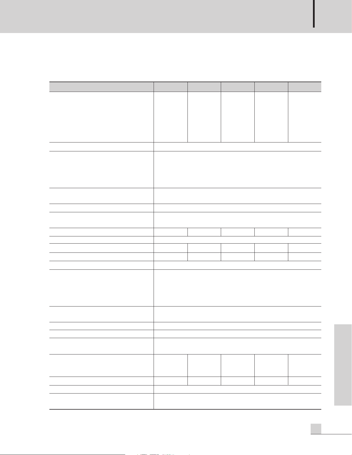
AMPLIFICADOR PROFESIONAL
61
L800/1400/1800/2400/3000
Spanish
Especificaciones
Especificaciones
0dB=1Vrms, Media Potencia = 1/2 Nivel de Potencia de Salida (especificada))
* Especificaciones y cambios sin previo aviso.
L800 L1400 L1800 L2400 L3000
Potencia de Salida
ESTEREO
1kHz con ambos canales funcionando
RL=8Ω @ 0.1% THD 200W 280W 360W 500W 650W
R
L
=4Ω @ 0.1% THD 300W 450W 600W 750W 1000W
R
L
=2Ω @ 0.5% THD 430W 700W 900W 1200W 1500W
PUENTE R
L
=8Ω 1kHz @ 0.1% THD 600W 900W 1200W 1500W 2000W
R
L
=4Ω 1kHz @ 0.5% THD 800W 1400W 1800W 2400W 3000W
Respuesta en Frecuencia R
L
=8Ω, P=1W 20Hz~20kHz: ±0/1dB, 5Hz~70kHz: -3dB
Distorsión Armónica Total
f=20Hz~20kHz, Media potencia (L800/1400)
1/10 de Potencia (L1800/2400/3000)
ESTEREO R
L
=8Ω & 4Ω≤0.03%
PUENTE R
L
=8Ω≤0.03%
Separación de canales a media potencia R
L
=8Ω,
f=1kHz, (ATT max.) Con carga de 600Ω en la entrada
≥80dB
Ruido residual (con filtro de audio DIN) ≤-85dB: ATT min.
Relación señal a ruido (DIN Audio),
con carga de 600Ω en la entrada. ≥100dB
Input Sensitivity (Rated Power into 4Ω 1kHz) 2.7dBu 2.7dBu 3.5dBu 3.5dBu 3.5dBu
Damping Factor R
L
=8Ω, f=1kHz ≥400
Sensibilidad de entrada (A potencia especificada en 4Ω a 1kHz)
30dB 32dB 33dB 34dB 38.5dB
Circuiteria de Salida Clase AB Clase AB Clase H Clase H Clase H
Impedancia de entrada (ATT max.) ≥20kΩ Balanceada / Desbalanceada
Indicadores Encendido (Azul)
Saturación/Limitador (Rojo)
Señal (Verde)
Protección (Rojo)
Selector de Modo (Ambar)
Protección Silenciamiento en ON/OFF, Protección a Corto circuito,
Protección térmica y de RF
Circuito de ventilador Baja velocidad - Velocidad variable - Alta velocidad
Operativo Temperatura -10°C ~ +40°C
Fuente de energía 100-120VCA o 220-240VCA; 50/60Hz
(El transformador incluido depende del requerimiento del país)
Consumo de energía (1/8 de la potencia)
100V-120VCA Ambos canales operando
RL=4Ω 6A 7A 8A 9A 11A
230V-240VCA Ambos canales operando
RL=4Ω 3A 3.5A 4A 4.5A 5A
Peso
14kg/30.8lb 14.4kg/31.7lb 15kg/33lb 15.6kg/34.6lb 19.5kg/39.5lb
Dimensiones
482(Ancho)x88(Alto)x369(Fondo)mm/19(Ancho)x3.5(Alto)x14.5(Fondo) pulgadas
Conectores Entradas: Balanceadas en conector combinado (XLR y 1/4" TRS)
Salidas: 2 juegos de bornes de 5 lados, 2 conectores "Speakon"
Page 64

AMPLIFICADOR PROFESIONAL
62
L800/1400/1800/2400/3000
Spanish
Servicio
Servicio
Procedimientos
Asegúrese que el problema no tiene que ver con el operador o con dispositivos externos. Una vez que está
seguro que el problema se relaciona con el producto, contacte a su proveedor de garantía como se describe en
la sección de garantía de este manual.
Diagramas
El diagrama está disponible contactando a su proveedor de garantía.
Lista de Partes
La lista de partes está disponible contactando a su proveedor de garantía.
Variaciones y Opciones
Variaciones y Opciones
Variaciones
Existen algunas variaciones de este producto que tienen que ver con los requerimientos de corriente alterna
para diferentes partes del mundo.
Los productos vendidos localmente son compatibles con los requerimientos de corriente alterna de la localidad.
Opciones
No hay artículos opcionales disponibles para este producto.
Garantía
Garantía
Los términos de garantía y condiciones pueden variar de un país a otro y pueden no ser los mismos para todos
los productos. Los términos y condiciones de garantía pueden ser determinados de manera local en el país
donde el producto fue comprado.
Para obtener información especifica de garantía y ubicaciones de los centros de servicio disponibles, contacte a
Inter-M directamente o al distribuidor autorizado para su país o región.
Page 65

NOTE
Page 66

NOTE
Page 67

MADE IN KOREA
April 2007 9000000521
Inter-M, Ltd. (Korea) began operations in 1983.
Since then, Inter-M has grown to become one of the largest manufacturers
of professional audio and commercial sound electronics equipment in the world.
Inter-M has gained worldwide recognition for its own branded products,
as well as private label manufacturing of electronics sold under other names (OEM).
The company is no longer just a Korean company, but rather a global company
that is truly international in scope, with factories and offices in Korea and China,
and sales and marketing operations located in Japan, Europe, and the U.S.A.
With more than 850 employees around the globe,
Inter-M is well-poised for further growth and expansion.
Inter-M Americas, INC.
13875 ARTESIA BLVD. CERRITOS, CA 90703 USA
TEL : +1-562-921-0313, FAX : +1-562-921-0370
Home Page : http://www.inter-m.net, E-mail : info@inter-m.net
Inter-M Corporation
SEOUL OFFICE:653-5 BANGHAK-DONG, DOBONG-KU, SEOUL, KOREA
TEL : 82-2-2289-8140~8, FAX : 82-2-2289-8149
Home Page : http://www.inter-m.com, E-mail : overseas@inter-m.com
 Loading...