

Page 1
Operation Manual
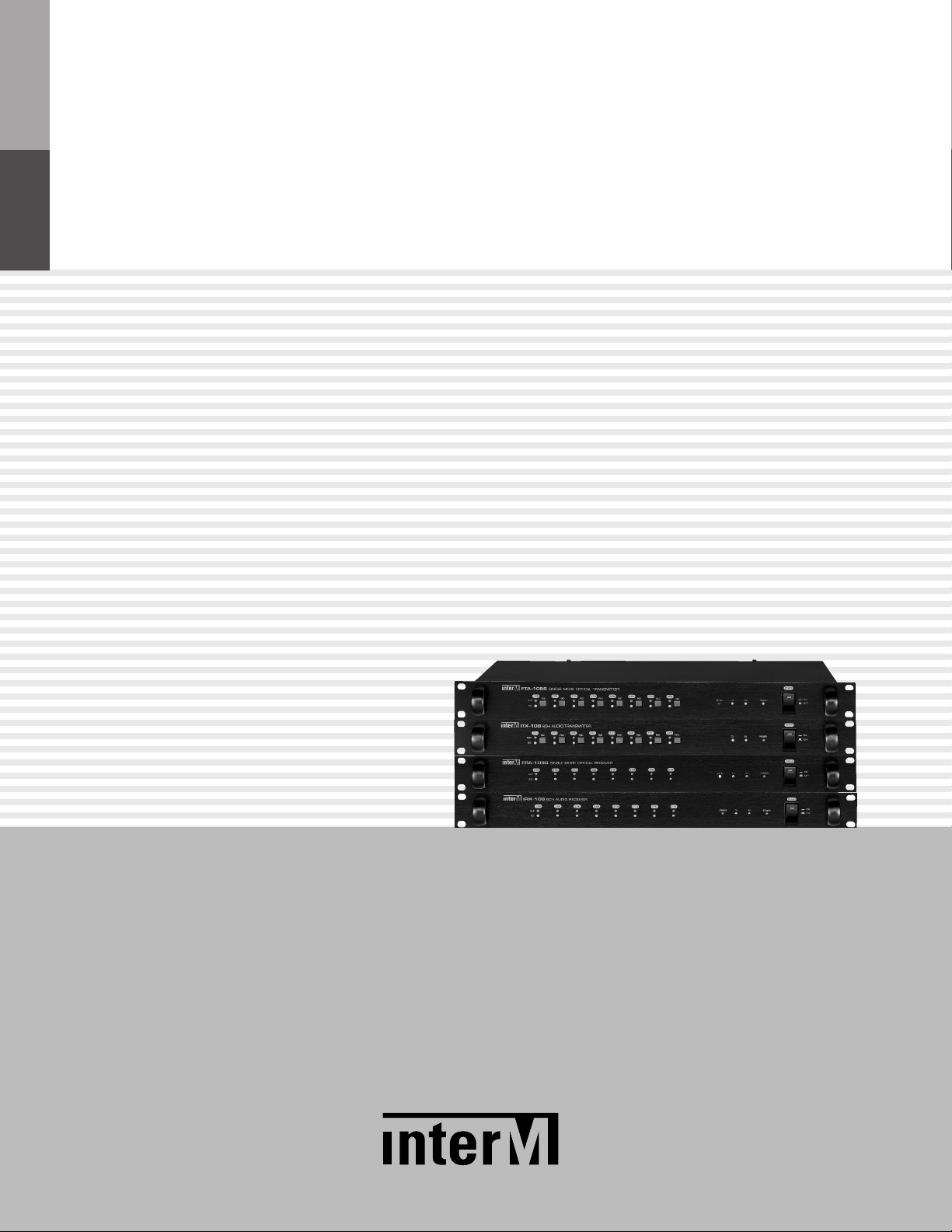
2/8 Channel Audio Transmitter/Receiver
Transmitter:
Receiver
* Rack mount products in the Western Hemisphere(North America, South America, and the Caribbean)
FTA-108S/ITX-108/ITX-102
:
FRA-108S/IRX-108/IRX-102
do not have handles installed due to customer preference.
Page 2
2/8 CHANNEL AUDIO TRANSMITTER/RECEIVER
Welcome
Welcome
A personal welcome to you from the management and employees of Inter-M
All of the co-workers here at Inter-M are dedicated to providing excellent products with inherently good value,
and we are delighted you have purchased one of our products.
We sincerely trust this product will provide years of satisfactory service, but if anything is not to your complete
satisfaction, we will endeavor to make things right.
Welcome to Inter-M, and thank you for becoming part of our worldwide extended family!
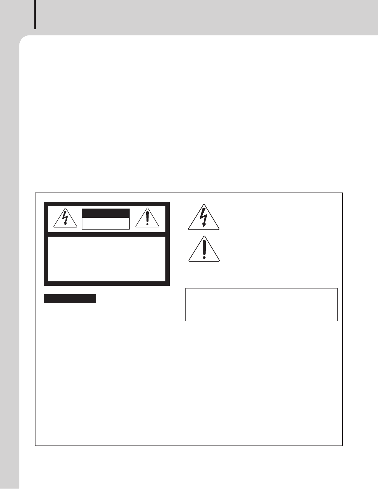
This symbol is intend ed to aler t the user to the
CAutION
RISK OF ELECTRIC SHOCK
DO NOT OPEN
CAUTION: TO REDUCE THE RISK OF ELECTRIC SHOCK.
DO NOT REMOVE COVER (OR BACK).
NO USER-SERVICEABLE PARTS INSIDE.
REFER SERVICING TO QUALIFIED SERVICE PERSONNEL.
Caution: To prevent electric shock do not use this (polarized) plug with
Attentions: Pour prévenir les chocs électriques ne pas utiliser cette
WARNING
To prevent fire or shock hazard, do not
expose the unit to rain or moisture.
*WARNING FOR YOUR PROTECTION PLEASE READ THE FOLLOWING-WATER AND MOISTURE: Unit should not be used near water(e.g.
near a bathtub, washbowl, kitchen sink, laundry tub, in a wet basement, or near a swimming pool, etc). Care should be taken so than objects do
not fall and liquids are not spilled into the enclosure through openings.
*Do not install this equipment in a confined space such as a book case or similar unit.
*This apparatus shall not be exposed to dripping or splashing and no objects filled with liquids, such vases, shall be placed on the apparatus.
*This apparatus shall be connected to a mains socket outlet with a protective earthing connection.
It has heed to be easy to disconnect the device. To disconnect the device from power, separate AC input cable from inlet or unplug the AC Cord.
*
*
The socket-outlet shall be installed near the equipment and shall be easily accessible.
CAutION
*These servicing instructions are for use by qualified service personnel only. To reduce the risk of electric shock, do not perform any servicing
other than that contained in the operating instructions unless you are qualified to do so.
NOtE
*This equipment has been tested and found to comply with the limits for a Class A digital device, pursuant to Part 15 of the FCC Rules. These limits are
designed to provide reasonable protection against harmful interference when the equipment is operated in a commercial environment. This equipment
generates, uses, and can radiate radio frequency energy and, if not installed and used in accordance with the instruction manual, may cause harmful
interference to radio communications. Operation of this equipment in a residential area is likely to cause harmful interference in which case the user will
be required to correct the interference at his own expense.
presence of uninsulated “dangerous voltage” within
the prod uct’s enclos ure t hat m ay be of suffi cient
magnitude to constitute a risk of electric shock to
persons.
This symbol is intend ed to aler t the user to the
presence of important operation and maintenance
(servicing) instructions in the literature accompanying
the appliance.
an extension cord, receptacle or other outlet unless the blades
can be fully inserted to prevent blade exposure.
fiche polarisée avec un prolongateur, une prise de courant
on une autre sortie de courant, sauf si les lames peuvent
étre insérées à fon d sa ns en laisser auc une par tie à
découvert.
Page 3

2/8 CHANNEL AUDIO TRANSMITTER/RECEIVER
Contents
Contents
Unpacking .......................................................................................................................................2
Installation
Environment....................................................................................................................................2
Important Safety Instructions.............................................................................................................2
Features............................................................................................................................................3
Front/Rear Panels of Transmitter
- Name and Function of Front Panel..................................................................................................4
- Name and Function of Rear Panel ..................................................................................................5
Front/Rear Panel of Receiver
- Name and Function of Front Panel..................................................................................................6
- Name and Function of Rear Panel ..................................................................................................7
Applications ....................................................................................................................................8
Assembling the Cables ..................................................................................................................9
RJ45 Data Protection Connector..................................................................................................9
Block Diagram ..............................................................................................................................10
Standards and Functions ............................................................................................................11
Service............................................................................................................................................12
Procedures....................................................................................................................................12
Schematic.....................................................................................................................................12
Parts List .......................................................................................................................................12
Variations and Options ...............................................................................................................12
Warranty .......................................................................................................................................12
FTA-108S/ITX-108/ITX-102, FRA-108S/IRX-108/IRX-102
1
Page 4

2/8 CHANNEL AUDIO TRANSMITTER/RECEIVER
S
3125A
Unpacking
Unpacking
Although your ECS-6216MS is neither complicated nor difficult to operate, we recommend you take a few
minutes to read this brief manual and familiarize yourself with the important information regarding product
features, setup and operation.
As with most electronic devices, we strongly recommend you retain the original packaging. In the unlikely event
the product must be returned for servicing, the original packaging (or reasonable equivalent) is required.
Installation
Installation
Environment
Never place this product in an environment which could alter its performance or reduce its service life. Such
environments usually include high levels of heat, dust, moisture, and vibration.
IMPORTANT SAFETY INSTRUCTIONS
1. Read these instructions.
2. Keep these instructions.
3. Heed all warnings.
4. Follow all instructions.
5. Do not use this apparatus near water.
6. Clean only with dry cloth.
7. Do not block any ventilation openings. Install in accordance with the manufacturer’s instructions.
8. Do not install near any heat sources such as radiators, heat registers, stoves, or other apparatus (including
amplifiers) that produce heat.
9. Do not defeat the safety purpose of the polarized or grounding-type plug. A polarized plug has two blades
with one wider than the other. A grounding type plug has two blades and a third grounding prong. The wide
blade or the third prong are provided for your safety. If the provided plug does not fit into your outlet, consult
an electrician for replacement of the obsolete outlet.
10. Protect the power cord from being walked on or pinched particularly at plugs, convenience receptacles, and
the point where they exit from the apparatus.
11. Only use attachments/accessories specified by the manufacturer.
12. Use only with the cart, stand, tripod, bracket, or table specified by the manufacturer, or sold with the apparatus.
When a cart is used, use caution when moving the cart/apparatus combination to avoid injury from tip-over.
13. Unplug this apparatus during lightning storms or when unused for long periods of time.
14. Refer all servicing to qualified service personnel. Servicing is required when the
apparatus has been damaged in any way, such as power-supply cord or plug is
damaged, liquid has been spilled or objects have fallen into the apparatus, the
apparatus has been exposed to rain or moisture, does not operate normally, or has
been dropped.
S3125A
2
FTA-108S/ITX-108/ITX-102, FRA-108S/IRX-108/IRX-102
Page 5

2/8 CHANNEL AUDIO TRANSMITTER/RECEIVER
Features
Features
Features
- TRANSMIT THE 2 CHANNEL AND 8 CHANNEL BALANCED AUDIO SIGNAL
2 Channel Model: ITX/IRX-102, 2 channel balanced audio signal transmission
8 Channel Model: FTA/FRA/ITX/IRX-108, 8 channel balanced audio signal transmission
- THE SOLUTION OF SENDING A SOUND SOURCE IN LONG DISTANCE
Optical Cable Communication [FTA/FRA-108S] : Sending a signal in long distance (maximum 15km)
UTP Cable Communication [ITX/IRX-108(102)] : Sending a signal in long distance (maximum 150m)
- HIGH QUALITY AUDIO SIGNAL
It sends the digital signal converted to 24Bit, 48kHz to provide the high quality audio signal
(higher than S/N 90dB, less than THD 0.01%)
- AC/DC SUPPORTS
It responses to the field conditions with supporting AC and DC power input terminals
- INPUT SENSITIVITY CONTROL FUNCTION THROUGH PAD SWITCHES
If it is clipped due to high input audio signal level, push the PAD switch to decrease the input signal in 10dB
- INPUT SIGNAL DISPLAY
Detects the audio signal and clip approved to each channel and display on the front panel.
- RS-232/RS-422/CONTACT POINT DATA RECEIVING/SENDING (OPTION MODULE)
The optional module (CT-100M/CR-100M) can be installed to make a possible to receive and send a RS-232,
RS-422 and 8 channel contact point data.
FTA-108S/ITX-108/ITX-102, FRA-108S/IRX-108/IRX-102
3
Page 6

2/8 CHANNEL AUDIO TRANSMITTER/RECEIVER
12 3 4 5 6
FTA-108S
ITX-108
Transmitter Front Panel (FTA-108S/ITX-108/ITX-102)
Transmitter Front Panel
1. INPUT SIGNAL DETECTING DISPLAY
Displays the input signal levels sending to each channel and green light will be on if -30dBV or higher is
supplied.
2. INPUT SIGNAL CLIP DISPLAY
Displays the clip status of input signal sending to each channel and red light will be on before signal clip.
3. PAD SWITCH
Pad switch to control the input level of each channel, and if signal clip occurs, push the signal to decrease
the input signal in 10dB to control the input level.
4. OPTICAL CABLE CONNECTION INDICATOR (FTA-108S)
Displays the connection of optical cable. Green light will be on if connection is normal and will be off if error
occurs on the connection.
5. DATA COMMUNICATION STATUS DISPLAY
If communication module (CT-100M) is installed, it displays the TX/RX data communication status of RS232C/RS-422.
6. POWER SWITCH AND INDICATOR
If this switch is pushed, power indicator will be on and equipment will be started.
4
FTA-108S/ITX-108/ITX-102, FRA-108S/IRX-108/IRX-102
Page 7

2/8 CHANNEL AUDIO TRANSMITTER/RECEIVER
12 34 5
FTA-108S
ITX-108
Transmitter Rear Panel (FTA-108S/ITX-108/ITX-102)
Transmitter Rear Panel
1. AC POWER INPUT TERMINAL
It receives the AC power.
2. DC POWER INPUT TERMINAL
It receives the DC 24V as the power input terminal.
3. AUDIO SIGNAL INPUT TERMINAL
Balanced audio signal input terminal.
+ : HOT
– : COLD
G : GROUND
4. COMMUNICATION TERMINAL
Terminal for data communication with receiver.
FTA-108S : Optical cable connection
ITX-102/108 : UTP cable connection.
PIN NAME PIN NAME PIN NAME
1 Rx+ 4 Tx+ 7 DA_OUT+
2 Rx– 5 N.C 8 DA_OUT3 Tx– 6 GND
5. COMMUNICATION MODULE CONNECTION SLOT
Slot for CT-100M communication module connection.
ITX-108/ITX-102
FTA-108S
※CT-100M is compatible with transmitters
(FTA-108S/ITX-108/ITX-102).
CR-100M is compatible with receivers
(FRA-108S/IRX-108/IRX-102).
Please check the model name when installing the module.
FTA-108S/ITX-108/ITX-102, FRA-108S/IRX-108/IRX-102
5
Page 8

2/8 CHANNEL AUDIO TRANSMITTER/RECEIVER
21345
FRA-108S
IRX-108
Receiver Front Panel (FRA-108S/IRX-108/IRX-102)
Receiver Front Panel
1. OUTPUT SIGNAL CLIP DISPLAY
Displays the clip status of input signal sending to each channel and red light will be on before signal clip.
2. OUTPUT SIGNAL DETECTING DISPLAY
Displays the output signal levels sending to each channel and green light will be on if -30dBV or higher is
output.
3. OPTICAL CABLE CONNECTION STATUS/ERROR INDICATOR
FTA-108S : if optical cable is connected normally, red light will be on.
ITX-108(102) : red light will be on if communication error occurs on the digital audio signal.
4. DATA COMMUNICATION STATUS INDICATOR
If communication module (CR-100M) is installed, it displays the TX/RX data communication status of RS232C/RS-422.
5. POWER SWITCH AND INDICATOR
If this switch is pushed, power indicator will be on and equipment will be started.
6
FTA-108S/ITX-108/ITX-102, FRA-108S/IRX-108/IRX-102
Page 9

2/8 CHANNEL AUDIO TRANSMITTER/RECEIVER
12 34 5
FRA-108S
IRX-108
Receiver Rear Panel (FRA-108S/IRX-108/IRX-102)
Receiver Rear Panel
1. AC POWER INPUT TERMINAL
It receives the AC power.
2. DC POWER INPUT TERMINAL
It receives the DC 24V.
3. AUDIO SIGNAL INPUT TERMINAL
Balance audio signal input terminal.
+ : HOT
– : COLD
G : GROUND
4. COMMUNICATION TERMINAL
Terminal for data communication with receiver.
FTA-108S : Optic cable connection
ITX-102/108 : UTP cable connection.
PIN NAME PIN NAME PIN NAME
1 Tx+ 4 Rx+ 7 DA_OUT+
2 Tx– 5 N.C 8 DA_OUT3 Rx– 6 GND
5. COMMUNICATION MODULE CONNECTION SLOT
Communication Module Connection Slot
Slot for CT-100M communication module connection.
IRX-108/IRX-102
FRA-108S
※CT-100M is compatible with transmitters
(FTA-108S/ITX-108/ITX-102).
CR-100M is compatible with receivers
(FRA-108S/IRX-108/IRX-102).
Please check the model name when installing the module.
FTA-108S/ITX-108/ITX-102, FRA-108S/IRX-108/IRX-102
7
Page 10

2/8 CHANNEL AUDIO TRANSMITTER/RECEIVER
DSC-8200A
DAP-8288A
DSS-8232A
DRG-8232A
DAP-8288A
DSS-8232A
DRG-8232A
FTA-108S
or ITX-108
FRA-108S
or IRX-108
OPTIC CABLE or
UTP CABLE
T
U
C
OUNTER
RESET
AB
LRdB
2
RECMEMORELAYBLANK DUBBING
NORHIGHPLAYSKIP
063
LEVEL
11
PHONES
P
OWER
O
N
OFF
d
D
ECK BDECKA
MIN MAX
REC LEVEL
MIN MAX
OUTPUT LEVEL
D
UBBINGNOR HIGH
OPEN OPEN
AMS AMS AMS AMS
STEREO DOUBLE CASSETTE DECK
PC
6335
SKIP/B REC PAUSE
REC
MUTE
R/PLAYMEMO
MODE
DECKA
AUTO REVERSE
PLAY LOGIC DECK
DECK B
AUTO REVERSE
RECORDING PLAY LOGIC DECK
T
UNER
M
IC
CDP
DECK
Applications
Applications
8
FTA-108S/ITX-108/ITX-102, FRA-108S/IRX-108/IRX-102
Page 11

Assembling a Cable
UTP
18 18
[ TOP VIEW ]
DIRECT
[ CABLE COLOR ORDER ]
[ FRONT VIEW ]
8.Brown
7.W/Brown
6.Green
5.W/Blue
4.Blue
3.W/Green
2.Orange
1.W/Orange
Assembling a Cable
ITX-108, IRX-108, ITX-102, IRX-102 is connected with CAT5 line.
]
2/8 CHANNEL AUDIO TRANSMITTER/RECEIVER
※Caution : when making CAT5 CABLE, please make it with Direct
RJ45 Data Protection Connector
RJ45 Data Protection Connector
]
※Caution : when making CAT5 CABLE, please make it with Direct
※Caution : [Related to protection connector assembling]
- Connector for ITX-108 and IRX-108 : assemble the both ends of UTP Cable by using NE8MC protection connector
FTA-108S/ITX-108/ITX-102, FRA-108S/IRX-108/IRX-102
9
Page 12

2/8 CHANNEL AUDIO TRANSMITTER/RECEIVER
ITN
Decoder
MCU
50/60Hz
DC 24V
AC 220~240V
SMPS
+15V
-15V
+5V
AC/DC
DC/DC
RS-232
D
RIVER
RS-422/485
DRIVER
8
CH CONTACT
O
UTPUT
DATA
C
ONTROL
OPTION
D/A
Converter
OUTPUT 1
OUTPUT 2
OUTPUT 3
OUTPUT 4
OUTPUT 5
OUTPUT 6
OUTPUT 7
OUTPUT 8
LED Driver
Signal
C
lip
LED Driver
S
ignal
C
lip
LED Driver
Signal
Clip
LED Driver
S
ignal
Clip
LED Driver
Signal
Clip
LED Driver
S
ignal
Clip
LED Driver
Signal
Clip
LED Driver
Signal
Clip
OPTICAL
DRIVER
OPTIC IN
L
G
N
1
3 4
7
T1
103922
- +
~
~
A/D
C
onverter
ITN
E
ncoder
MCU
50/60Hz
DC 24V
AC 220~240V
SMPS
+15V
-15V
+5V
AC/DC
DC/DC
RS-232
DRIVER
R
S-422/485
DRIVER
8
CH CONTACT
INPUT
DATA
CONTROL
PAD SW
INPUT 1
LED Driver
S
ignal
C
lip
-
16dB
P
AD SW
INPUT 2
L
ED Driver
S
ignal
C
lip
-
16dB
PAD SW
INPUT 3
L
ED Driver
S
ignal
Clip
-
16dB
P
AD SW
I
NPUT 4
LED Driver
Signal
Clip
-
16dB
P
AD SW
INPUT 5
LED Driver
S
ignal
Clip
-
16dB
P
AD SW
INPUT 6
LED Driver
S
ignal
C
lip
-
16dB
P
AD SW
INPUT 7
LED Driver
Signal
Clip
-16dB
P
AD SW
INPUT 8
LED Driver
Signal
C
lip
-
16dB
OPTION
OPTICAL
DRIVER
OPTIC OUT
L
G
N
1
3
4
7
T1
103922
-+
~
~
Block Diagram
Block Diagram
-FTA-108S/ITX-108/ITX-102
-FRA-108S/IRX-108/IRX-102
10
FTA-108S/ITX-108/ITX-102, FRA-108S/IRX-108/IRX-102
Page 13

Specifications
440
482
44
280
Specifications
Input Sensitivility 0dBV/20kΩ
THD Less than 0.01%
S/N(Rated input max) More than 90dB
Frequency Response 20Hz ~ 20kHz
Channel Separation More than -90dB
Data Rate 24Bit, 48kHz Sampling
Operating Temperature -10°C ~ +40°C/14°F~104°F
Power Source AC 220V, 60Hz
Power Consumption AC 18W, DC 24V, 600mA
Weight (Set) 4.2kg/9.3lbs
Dimensions (Set) 482(W)x44(H)x280(D)mm/19(W)x1.7(H)x11(D)in
※Specifications and design are subject to change without notice.
2/8 CHANNEL AUDIO TRANSMITTER/RECEIVER
ITX-102/ITX-108/IRX-102/IRX-108/FTA-108S/FRA-108S
※ DIMENSIONS
FTA-108S/ITX-108/ITX-102, FRA-108S/IRX-108/IRX-102
11
Page 14

2/8 CHANNEL AUDIO TRANSMITTER/RECEIVER
Service
Service
Procedures
Take steps to insure the problem is not related to operator error or other products within the system. Information
provided in the troubleshooting portion of this manual may help with this process. Once it is certain that the
problem is related to the product contact your warranty provider as described in the warranty section of this
manual.
Schematic
A Schematic is available by contacting your warranty provider.
Parts List
A Parts List is available by contacting your warranty provider.
Variations and Options
Variations and Options
Variations
Variations of this product exist to reflect the variations in AC power requirements throughout the world. Product
supplied through local sources are compatible with local AC power requirements.
Options
No optional items are available for this product.
Warranty
Warranty
Warranty terms and conditions vary by country and may not be the same for all products. Terms and conditions
of warranty for a given product may be determined first by locating the appropriate country which the product
was purchased in, then by locating the product type.
To obtain specific warranty information and available service locations contact Inter-M directly or the
authorized Inter-M Distributor for your specific country or region.
12
FTA-108S/ITX-108/ITX-102, FRA-108S/IRX-108/IRX-102
Page 15

FTA-108S/ITX-108/ITX-102, FRA-108S/IRX-108/IRX-102
13
Page 16

Inter-M, Ltd. (Korea) began operations in 1983.
Since then, Inter-M has grown to become one of the largest manufacturers
of professional audio and commercial sound electronics equipment in the world.
Inter-M has gained worldwide recognition for its own branded products,
as well as private label manufacturing of electronics sold under other names (OEM).
The company is no longer just a Korean company, but rather a global company
that is truly international in scope, with factories and offices in Korea and China,
and sales and marketing operations located in Japan, Europe, and the U.S.A.
With more than 850 employees around the globe,
Inter-M is well-poised for further growth and expansion.
Inter-M Americas, INC.
13875 ARTESIA BLVD. CERRITOS, CA 90703 USA
TEL : +1-562-921-0313, FAX : +1-562-921-0370
Home Page : http://www.inter-m.net, E-mail : info@inter-m.net
Inter-M Corporation
SEOUL OFFICE:653-5 BANGHAK-DONG, DOBONG-KU, SEOUL, KOREA
TEL : +82-2-2289-8140~8, FAX : +82-2-2289-8149
Home Page : http://www.inter-m.com, E-mail : overseas@inter-m.com
MADE IN KOREA
September 2012 129494
 Loading...