

Page 1

IMN-511/512
High Resolution IP Camera
Operation
Manual
* Before starting use of this product, be sure to check the broadcasting
mechanism and the power voltage.
Page 2

IMN-511/512
O/P Manual
Although it is neither complicated to install nor difficult to operate your
set, a few minutes of your time is required to read this manual for a
properly wired installation and becoming familiar with its many
features and how to use them. Please take a great care in unpacking
your set and do not discard the carton and other packing materials.
They may be needed when moving your set and are required if it
ever becomes necessary to return your set for service.
Never place the unit near radiators, in front of heating vents, in
excessively humid or dusty location to avoid early damage and for
your years of quality use. Connect your complementary components
as illustrated in the following page.
Auto Iris Plug S/W & Manual CD
Page 3

1
IMN-511/512(HIGH RESOLUTION IP CAMERA)
Overview ............................................................................2
Features..............................................................................3
Precautions........................................................................5
Part Names and Function.................................................8
Rear Names and Function..............................................10
Installing IMN-511/512.....................................................13
1. Lens Mounting and Connection .................................13
2. Lens Adjustment.........................................................18
3. Connecting a Monitor .................................................22
4. Connection method for MIC and Speaker..................24
5. Connecting a network.................................................24
6. Connecting Sensor In/Out ..........................................25
7. Connecting PAN/TILT ................................................26
Setting IP Address ..........................................................27
Camera Setup ..................................................................32
Specifications..................................................................35
Trouble Shooting ............................................................37
Page 4

2
IMN-511/512(HIGH RESOLUTION IP CAMERA)
IMN-511/512(series) is 540 High Resolution DAY & NIGHT
Network Camera adopting SONY CCD with 410,000 pixels of
high picture quality, which is a color camera realizing 0.01Lux
with lowest light intensity.
It supports high quality MPEG-4, connected with Ethernet or
xDSL/Cable modem at the speed of 30 frames/sec.
The transmitted image can be monitored from any place with a
computer having Microsoft Internet Explorer installed.
It offers users access to high quality video and audio from any
workstation on the LAN/WAN. The Network Camera is ideal for
surveillance applications that require high quality, full motion
video and audio, as well as comparatively low bandwidth
demands on the network. Also, this system provides remote
users in the Internet with alarm processing function and remote
control on PAN/TILT/ZOOM/FOCUS.
The built-in Web server provides its own application page for
direct viewing of the network camera, as well as full web-based
control of the management and configuration functions. All of
this can be accessed from a browser over the network.
Page 5

3
IMN-511/512(HIGH RESOLUTION IP CAMERA)
■■
■■
Video
- Adopts 1/3” 410,000 pixel high fidelity SONY CCD
- 540TV LINES Horizontal resolution(Color), 570TV
LINES(B/W)
- Minimum 0.01Lux by transmission of IR-CUT Filter(F1.2)
- Day & Night(IR CUT FILTER) Function
- High-speed automatic shutter(ELC) function
- Back Light Compensation(BLC
- Flickerless function
- Auto gain Control(AGC) function
- Supports mounting of DC/VIDEO iris lens
- Possible to install C/CS Mount lens
■■
■■
Video Compression
- High Resolution live video up to 30fps
- Compression: MPEG4, MJPEG selectable
- Resolution: D1, VGA, QVGA, 4CIF, CIF, QCIF
- Bandwidth Utilization Control by user
- BitRate : 0.256 ~ 4Mbps per Client
■■
■■
Video out
- One Composite Loop-out (75Ω Auto-termination)
■■
■■
Video Motion Detection
- Streamer Based motion detection
- 20*15 cell
- 0 ~ 100 Sensitivity Resolution
■■
■■
Networking
- ARP, ICMP, TCP/IP, UDP/IP, RTP/RTSP, HTTP server,
FTP Server, SMTP client, TIME client, FTP client, DHCP
client
- 10/100 Base-T Fast Ethernet (Auto Negotiation)
Page 6

4
IMN-511/512(HIGH RESOLUTION IP CAMERA)
■■
■■
Security
- IP Address Filtering
- Multi-level password protection
■■
■■
Audio Compression
- Linear PCM 8KHz, 16bit Mono
- Bi-directional Audio
■■
■■
Audio In/out
- External Microphone
- Speaker output
■■
■■
Connections & Connectors
- 485 Transceiver
- 1 Sensor Input (normal open/normal close selectable)
- 1 Relay Output
■■
■■
Power
- Power Source - 12VDC Adapter
- Power consumption 7.2Watt@12VDC for IMN-511
8.4Watt@12VDC for IMN-512
Page 7

5
IMN-511/512(HIGH RESOLUTION IP CAMERA)
RISK OF ELECTRIC SHOCK
DO NOT OPEN
CAUTION
CAUTION: TO REDUCE THE RISK OF ELECTRIC SHOCK.
DO NOT REMOVE COVER (OR BACK).
NO USER-SERVICEABLE PARTS INSIDE.
REFER SERVICING TO QUALIFIED SERVICE PERSONNEL.
WARNING
To prevent fire or shock hazard, do not expose the unit to rain or moisture.
This symbol is intended to alert the user to the presence of
uninsulated “dangerous voltage” within the product’s
enclosure that may be of sufficient magnitude to constitute a
risk of electric shock to persons.
This symbol is intended to alert the user to the presence of
important operation and maintenance (servicing) instructions
in the literature accompanying the appliance.
Caution: These servicing instructions are for use by qualified service
personnel only. To reduce the risk of electric shock, do not any
perform any servicing other than that contained in the operating
instructions unless you are qualified to do so.
Attentions: Pour prévenir les chocs électriques ne pas utiliser cette fiche
polarisée avec un prolongateur, une prise de courant on une
autre sortie de courant, sauf si les lames peuvent étre
insérées à fond sans en laisser aucune partie à découvert.
Page 8

6
IMN-511/512(HIGH RESOLUTION IP CAMERA)
Warning
DO NOT ATTEMPT TO INSTALL THE
PRODUCT YOURSELF.
WHEN SMOKE OR ABNORMAL HEAT
EMISSION IS DETECTED, STOP USING THE
CAMERA.
It can result in fire. In this case, stop
using the camera and refer servicing
to a local agency or the Customer
Service Department in the
headquarters.
This product must be installed by qualified
personnel. Trying to install the product yourself
can cause a risk of fire or electric shock.
Thus, the user should
consult with a nearby
agency for
proper permitting.
DO NOT INSTALL THE PRODUCT IN DUSTY
OR DAMP PLACES WITH POOR
VENTILATION OR PLACES WITH OIL OR
GAS.
DO NOT PLACE THE PRODUCT IN
UNSTABLE PLACES WITH VIBRATION OR
ON A SLANTED SURFACE OR IN PLACES
WITHOUT SECURE MOUNTINGS.
The product must be
securely fastened to
avoid mounting failure
that can inflict damage
to the product and even
jeopardize a person’s
life.
It will cause the abnormal
operation of the product or
result in a risk of electric
shock or fire.
DO NOT GRASP OR PULL THE POWER
CORD OR PLUG WITH WET HANDS.
DO NOT DISSEMBLE THE PRODUCT OR
INSERT UNDESIRED FOREIGN
SUBSTANCES.
When the cord or plug is
damaged or frayed, it can
cause fire or electric shock.
It will result in the abnormal
operation of the product and fire.
This sign is provided to alert the user to the presence of possible
hazards that could cause serious injury or even death.
Warning
This sign is intended to alert the user to the presence of possible
hazards that could cause personal injury or property damage.
Caution
Page 9

7
IMN-511/512(HIGH RESOLUTION IP CAMERA)
DO NOT INSTALL THE CAMERA IN EXTREME
TEMPERATURE CONDITION
DO NOT INSTALL THE CAMERA UNDER
UNSTABLE LIGHTING CONDITION
Unstable lighting can
cause the camera to work
improperly. If the
camera is exposed to
spotlight or object
reflecting strong light,
smear or blooming
may occur.
Do not use the camera under
condition where temperature
is over -10°C to 50°C.
Especially be careful for
ventilation
under high
temperature.
DO NOT DROP OR SHAKE THE CAMERA DO NOT INSTALL THE CAMERA FACE UNDER
STRONG LIGHTING CONDITION
It can cause
malfunction of CCD.
It can cause malfunction.
DO NOT TOUCH THE LENS DO NOT INSTALL THE CAMERA UNDER WET
OR RAIN
It can cause the image
quality to be poor.
If it gets wet, it can cause the
camera out of order.
DO NOT INSTALL THE CAMERA CLOSELY AT
THE MAGNETIC
DO USE A DRY CLOTH TO CLEAN THE
CAMERA
It can cause malfunction. To sweep the camera, use a dry
and soft cloth.
* Please check that the power satisfies the normal specification before
connecting the camera.
This sign indicates practices considered ‘unacceptable’ during use of the product.
This sign illustrates mandated practices during use of the product.
Caution
Page 10

8
IMN-511/512(HIGH RESOLUTION IP CAMERA)
Page 11

9
IMN-511/512(HIGH RESOLUTION IP CAMERA)
11
11. FLANGE BACK ADJUST RING
When use of CS-MOUNT LENS, adjust Flange Back (When
use of C-MOUNT LENS, adjust by fixing optional C-MOUNT
ADAPTOR)
22
22. FLANGE BACK FIXING SCREW
Upon completion of the Flange Back focus, turn the flange
back focus fixing screw clockwise and fix the flange back
focus adjustment ring.
33
33. SUPPORTER FIXING EQUIPMENT
It is for the application of wall or ceiling installation. It is
available to use on the top or bottom of camera. If user want
to change the position, please use same screw to fix it from
other position. It may cause unexpected defectiveness once
you use other type of screw.
* No supplying of Supporter(Bracket, Triangle bar,
Housing)
Page 12

10
IMN-511/512(HIGH RESOLUTION IP CAMERA)
8 9 10 11
Page 13

11
IMN-511/512(HIGH RESOLUTION IP CAMERA)
11
11. SERIAL TERMINAL PORT
Connects to “RS-485 communication cable” for PAN/TILT/
ZOOM/FOUCS Controllers
- + : Connects to “+” port of RS-485 communication cable
- – : Connects to “–” port of RS-485 communication cable
22
22. SENSOR IN/OUT PORT
Connects to 1 sensor input and 1 output(TTL)
- IN : Connects to “+” port of the Sensor Input
- OUT : Connects to “+” port of the Sensor Output
- GND : GROUND
33
33. AUDIO IN/OUT PORT
Connects to 1channel MIC and 1channel speaker
- SPK : Connects to “+” port of the Speaker
- MIC : Connects to “+” port of the MIC
- GND : GROUND
44
44. LAN(ETHERNET) PORT
Connects to Ethernet(10/100Base-T) and xDSL/Cable
modem network with RJ-45 Connector.
*Supportable network type : LAN(10/100 Base-T)
55
55. POWER INPUT TERMINAL
Supplies the power to IMN-511/512 with a DC 12V input
terminal.
External Power : DC Power Adaptor(12V)
Power Consumption : 7.2Watt@12V DC for IMN-511
8.4Watt@12V DC for IMN-512
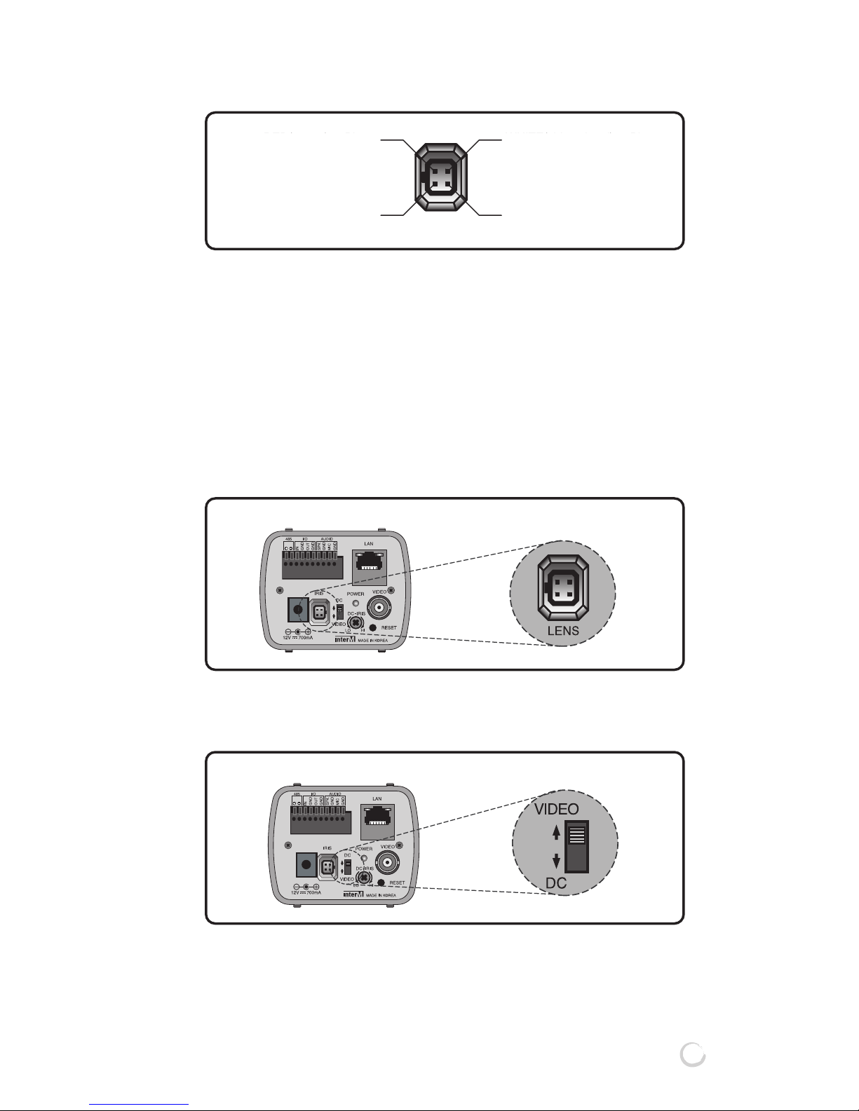
66
66. AUTO IRIS LENS CONNECTION PORT
It is a port for connection of a video iris lens or DC iris lens, if
they are used.
77
77. AUTO IRIS SELECTION SWITCH
With an auto iris lens mounted, you can select DC iris lens or
a video iris lens using this switch.
Page 14

12
IMN-511/512(HIGH RESOLUTION IP CAMERA)
88
88
. POWER LED
Indicates the power supply status of a camera. The power
lamp turns on when power is properly supplied.
99
99
. DC IRIS LENS ADJUSTMENT
It is a volume to adjust the brightness of DC iris lens. Turning
this volume to the left makes it darker, and to the right,
brighter.
111100
00
. FACTORY RESET BUTTON
IMN-511/512 parameters restored factory default values.
* Default IP Address : 192.168.1.100
Subnet Mask : 255.255.255.0
Gate way : 192.168.1.1
111111
11
. VIDEO OUTPUT PORT
It is a video output port, which is set to 75Ω impedance.
Connect to the video input connector of monitor.
(See the installation method)
Page 15

13
IMN-511/512(HIGH RESOLUTION IP CAMERA)
This section is intended for use by the product administrator.
Operators and viewers should check the detail through
enclosed CD and manual file.
You may connect the following items with IMN-511/512, such as
lens mounting, connecting a monitor, network devices, audio
device, alarm sensors, Serial (PAN/TILT) controllers.
11
11
. LENS MOUNTING AND CONNECTION
* To make a correct adjustment, the help of an expert may
be required.
Connection method differs depending on lens types. So,
becareful about it when mounting lenses.
(Check the lens type to see if it is C MOUNT or CS MOUNT.)
You can use such lenses as C mount lens, CS mount
lens,and automatic iris lens, etc.
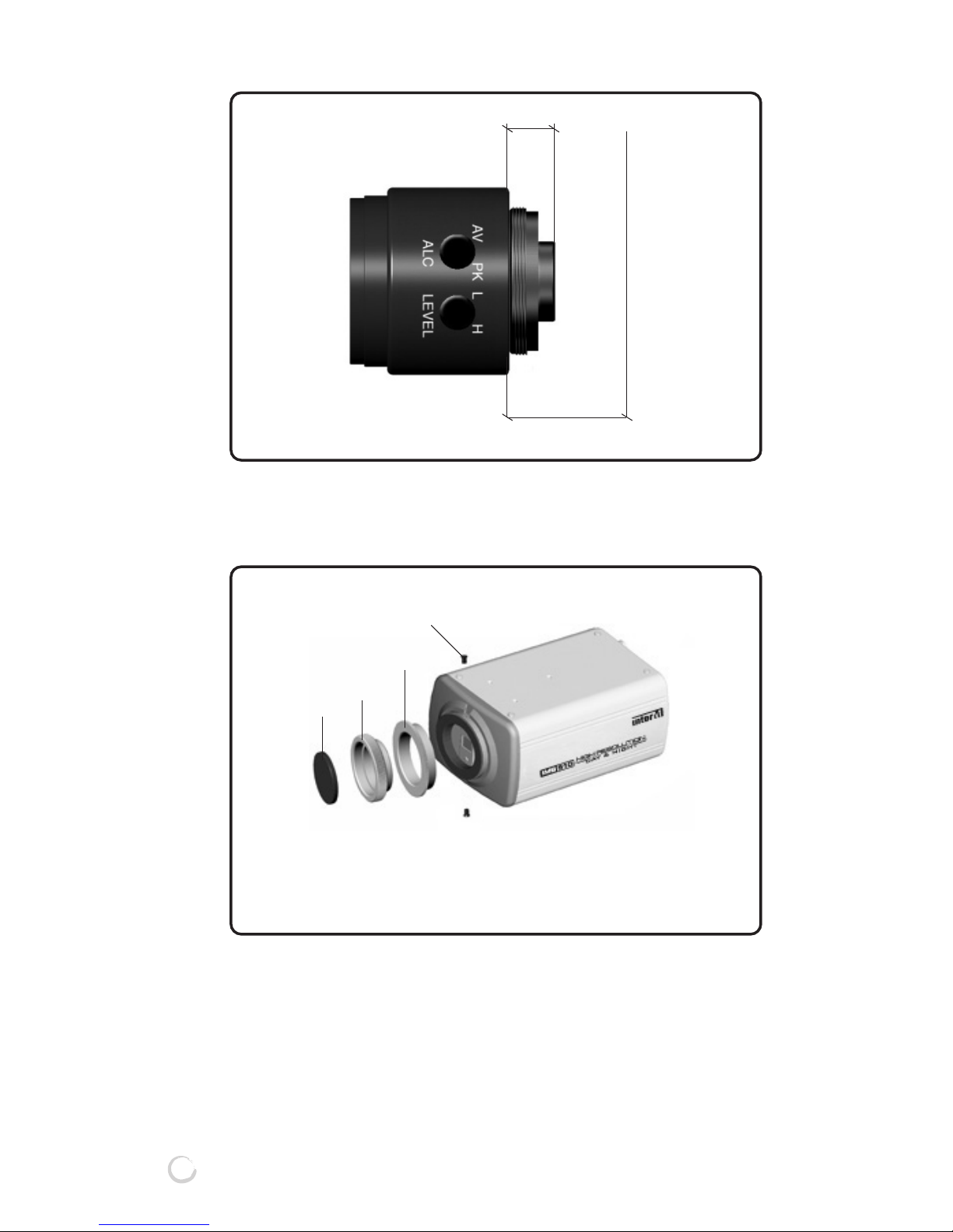
- Identification of a lens by lens mounting:
The flange back is the distance from the reference plane
(where a lens and a camera are coupled) to the focal plane. If
this distance is not determined accurately, you cannot get
accurate images.
LENSES Flange Back(B) Dimension(A)
C-mount Lens 17.526mm 10mm or below
CS-mount Lens 12.5mm 5.5mm or below
Page 16
14
IMN-511/512(HIGH RESOLUTION IP CAMERA)
F: the focal plane
B
A
F
■■
■■
CONNECTION METHOD FOR C MOUNT LENS AND CS
MOUNT LENS
Upon mounting a CS mount lens, assemble ❸.
Upon mounting a C mount lens, assemble
❷+❸
.
1. CAMERA ADAPTOR
2. C MOUNT ADAPTOR
3. CS MOUNT ADAPTOR
4. STOP SCREW
❶
❷
❸
❹
Page 17
15
IMN-511/512(HIGH RESOLUTION IP CAMERA)
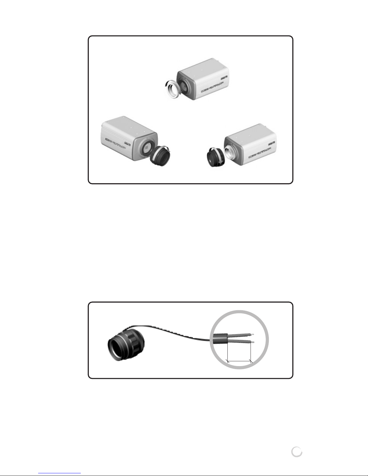
When using CS lens: As shown in Figure1, turn the CS lens
clockwise to connect it.
When using C lens: As shown in Figure2, connect the C
mount adaptor by turning it
clockwise, and then connect the C
lens by turning it clockwise as shown
in Figure3.
■■
■■
WHEN USING AN AUTO IRIS LENS
1) Peel off about 8mm of a lens cable’s covering from the end.
Figure1
Figure2
Figure3
8mm
Page 18

16
IMN-511/512(HIGH RESOLUTION IP CAMERA)
2) Peel off about 2mm of the inner wires from the end of the
lens cable.
3) Remove the cover of the lens connection plug, and connect
the lens cable wires to the connector pins of the connection
plug.
-
Wiring the Video Iris Lens
* What is a video iris lens? When the power and video
signals are supplied from the camera, if the video signal is
stronger than the specified value, this video iris lens
automatically moves the iris to the closing direction; and if
weaker, to the opening direction so as to provide the
constant image output even when the brightness of an object
is changed. The lens includes a circuit that controls an iris.
2mm
Lens Connector
1
2
4
3
Control Cable
Auto Iris Lens
Lens Connector Cover
RED(power) to Pin #1
N.C(not connected) to Pin #2
WHITE(video signal) to Pin #3
BLACK(ground) to Pin #4
Page 19
17
IMN-511/512(HIGH RESOLUTION IP CAMERA)
-
Wiring the DC Iris Lens
* What is a DC iris lens? A DC iris lens has only an iris
controlling coil which opens and closes an iris without an
iris controlling circuit inside a lens. So a lens controlling
circuit is configured in a camera to receive the control
signals (DC) sent by the camera lens so as to provide the
constant image output.
4) Connect the connection plug (connected to a lens cable) to
the auto lens connector on the back of the product.
5) If you use a DC iris lens, select DC from the lens selection
switch; if a video iris lens, select VIDEO.
* Recommend Auto Iris Lens in the condition of bad lighting
condition.(The place where lighting is continuously changing)
RED(power) to Pin #1
N.C(not connected) to Pin #2
WHITE(video signal) to Pin #3
BLACK(ground) to Pin #4
RED(DAMP -) to Pin #1 WHITE(DRIVE +) to Pin #3
GREEN(DRIVE -) to Pin #4
BLACK(DAMP +) to Pin #2
IMN-511/512
IMN-511/512
Page 20
18
IMN-511/512(HIGH RESOLUTION IP CAMERA)
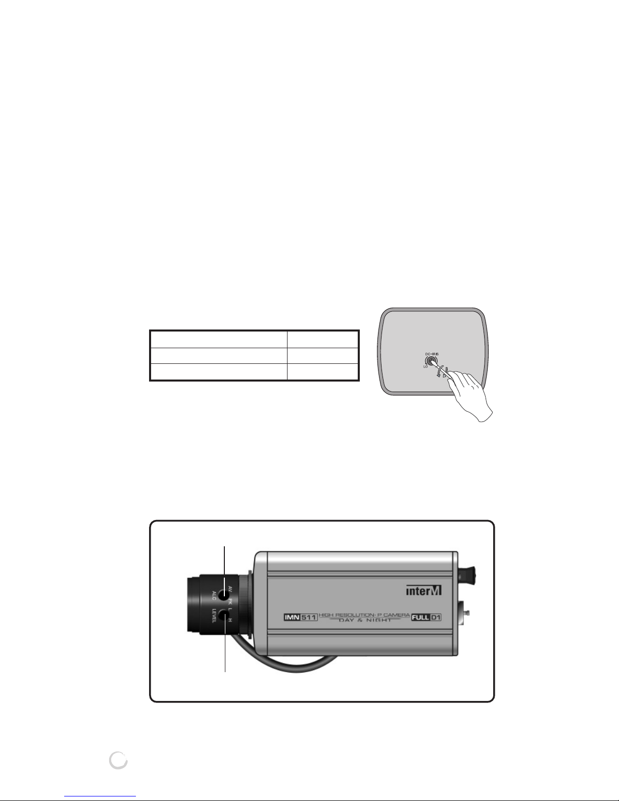
22
22. LENS ADJUSTMENT
* To make a correct adjustment, the help of an expert may
be required.
Re-adjustment of a lens may be required depending on the
conditions of an object and lens combination. To do this, turn
off the ELC switch on the back of the mainframe, and make
the adjustment in the following way.
■■
■■
IN CASE OF DC IRIS LENS
- Turn off the AGC switch on the back of the mainframe.
- Adjust the VR in rear panel of IMN-511/512 to control Iris.
- Select the AGC switch ON or OFF.
■■
■■
IN CASE OF VIDEO IRIS LENS
- Turn off the AGC switch on the back of the mainframe.
- Adjust the LEVEL and ALC of the Video Iris Lens.
- Select the AGC switch ON or OFF.
ALC adjust
LEVEL adjust
To make the monitor screen Turn the level
Darker anticlockwise
Brighter clockwise
Page 21

19
IMN-511/512(HIGH RESOLUTION IP CAMERA)
- Level Adjustment
- ALC Adjustment
*
Halation is the effect that occurs when the bright areas of an
image appear to softly bleed around the edges of dark areas
due to strong light.
* ALC(Automatic Light Control)
T
o keep the output level of a camera constant when the
amount of light changes, a turbo control system is applied to
the iris of a camera/lens system to control its opening and
closing. This system is included in the lens itself and
receives the power and video output from the camera. In
some system, a turbo system is included inside a camera,
and it is connected to a lens via 4 lines.
To make the monitor screen Turn the level
Darker anticlockwise
Brighter clockwise
Symptoms of a monitor Turn the level
When a halation occurs at a partial clockwise
area (a high brightness area) of a
screen
When the remaining area other than anticlockwise
a partial area (a high brightness
area) of a screen is abnormal
Page 22

20
IMN-511/512(HIGH RESOLUTION IP CAMERA)
■■
■■
ADJUSTING FLANGE BACK(BACK FOCUS)
Camera’s Flange Back comes out, adjusted from the
factory, however, according to the lens, adjustment required.
If required, please re-adjust like following.
1) In case of fixed focus lens, vari-focal lens.
① Adjust the angle of view to the subject.
② Adjust lens’ focus to the subject seen clearly. By this,
can check if the picture quality is good when the lens
does not have focus adjustment.
③ When not clearly seen, loosen the fixing screw and
make Flange back adjustment ring rotatable.
④ Rotate the Flange back adjustment ring to the turning
direction, and adjust to the subject seen clearly.
⑤ Tighten the Flange back fixing screw to fix the Flange
back adjustment ring, being careful of focus out.
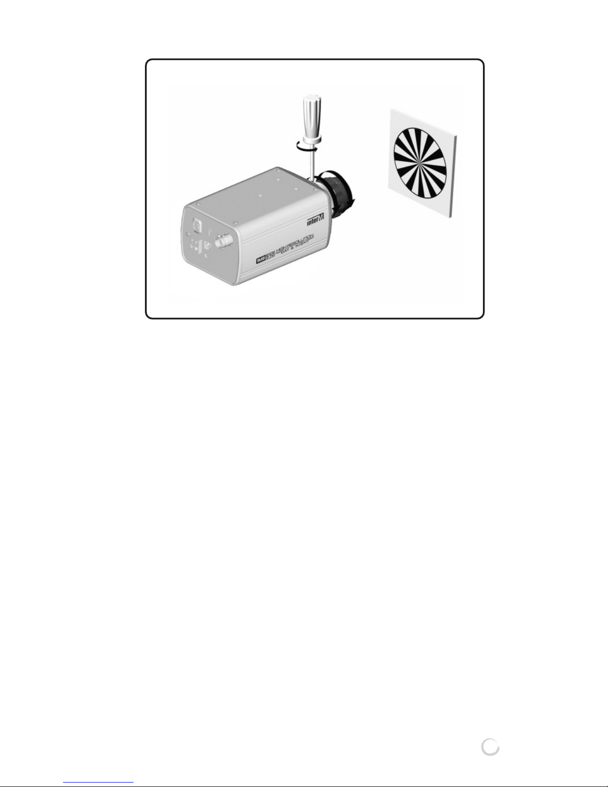
2) In case of zoom lens:
① Photograph an object with high clearness (located at
least 3 meters or more away)
② Set the lens zoom as maximum telephoto direction, and
adjust to the subject seen clearly. When not adjustable,
Flange back adjustment needed.
③ Flange back adjustment is right, if the subject seen
clearly when lens focus is same and zoom is maximum
wide-angle. If not clearly seen, flange back adjustment
needed.
④ To adjust flange back, loosen the flange back fixing
screw and make flange back adjust ring rotatable.
⑤ Set lens zoom as maximum telephoto direction, and
adjust focus to the subject seen clearly.
⑥ Lens focus location is same, and set zoom as maximum
wide-angle.
⑦ Rotate flange back adjust ring and make the subject
seen clearly.
⑧ Adjust more than 2 times repeatedly, between ⑤ and
⑦ to adjust correctly.
⑨ Set the lens zoom as maximum telephoto direction,
being careful not to focus out, holding flange back fixing
screw and fix flange back adjustment ring.
Page 23
■■
■■
CAUTIONS IN ADJUSTING FOCUS
Set the focus at a maximum telephoto status, and then
zoom in via wide angle.
If you set the focus with a wide angle, and then zoom in via
a telephoto mode, the focus may get out of focus. This is
because you can set the focus more accurately at a
telephoto mode than at a wide-angle mode. At a wide-angle
mode, you cannot identify the slight error in focus. But in at a
telephoto mode, you can identify the difference clearly as
you zoom in.
21
IMN-511/512(HIGH RESOLUTION IP CAMERA)
Page 24
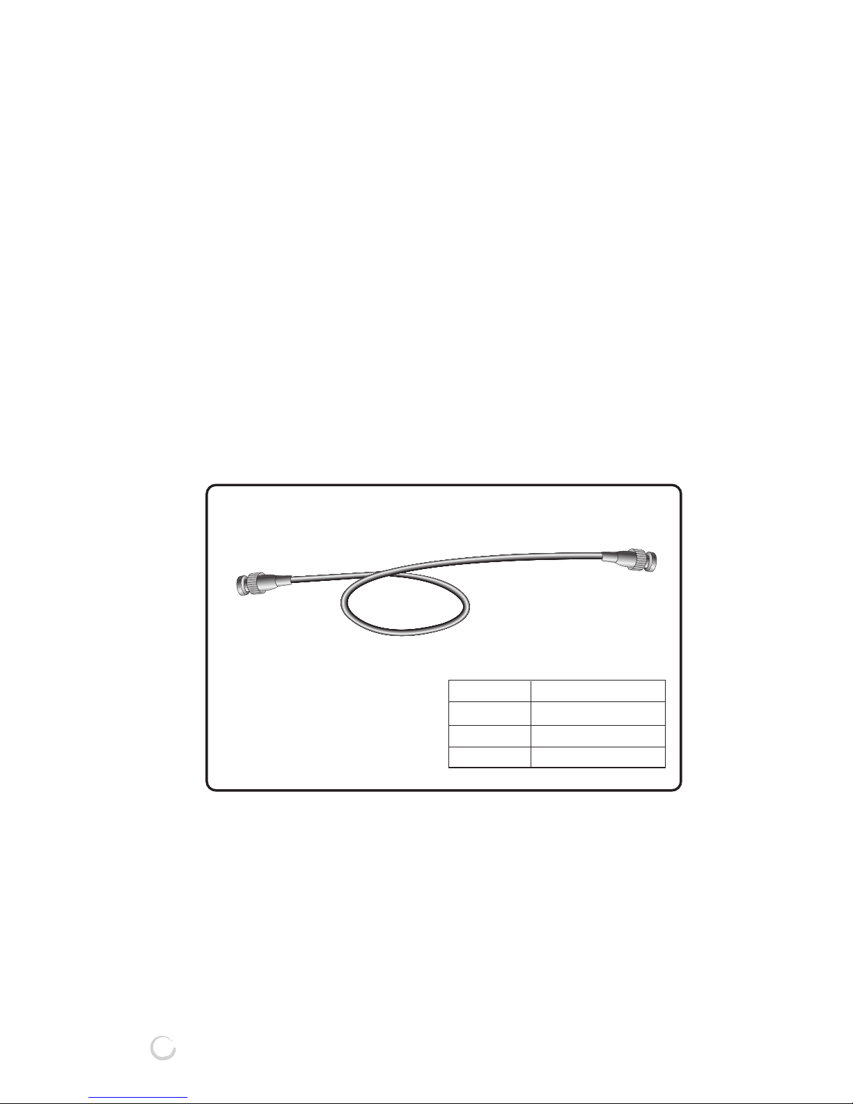
22
IMN-511/512(HIGH RESOLUTION IP CAMERA)
Cable
3C - 2V
5C - 2V
7C - 2V
Length(Max)
200m
350m
500m
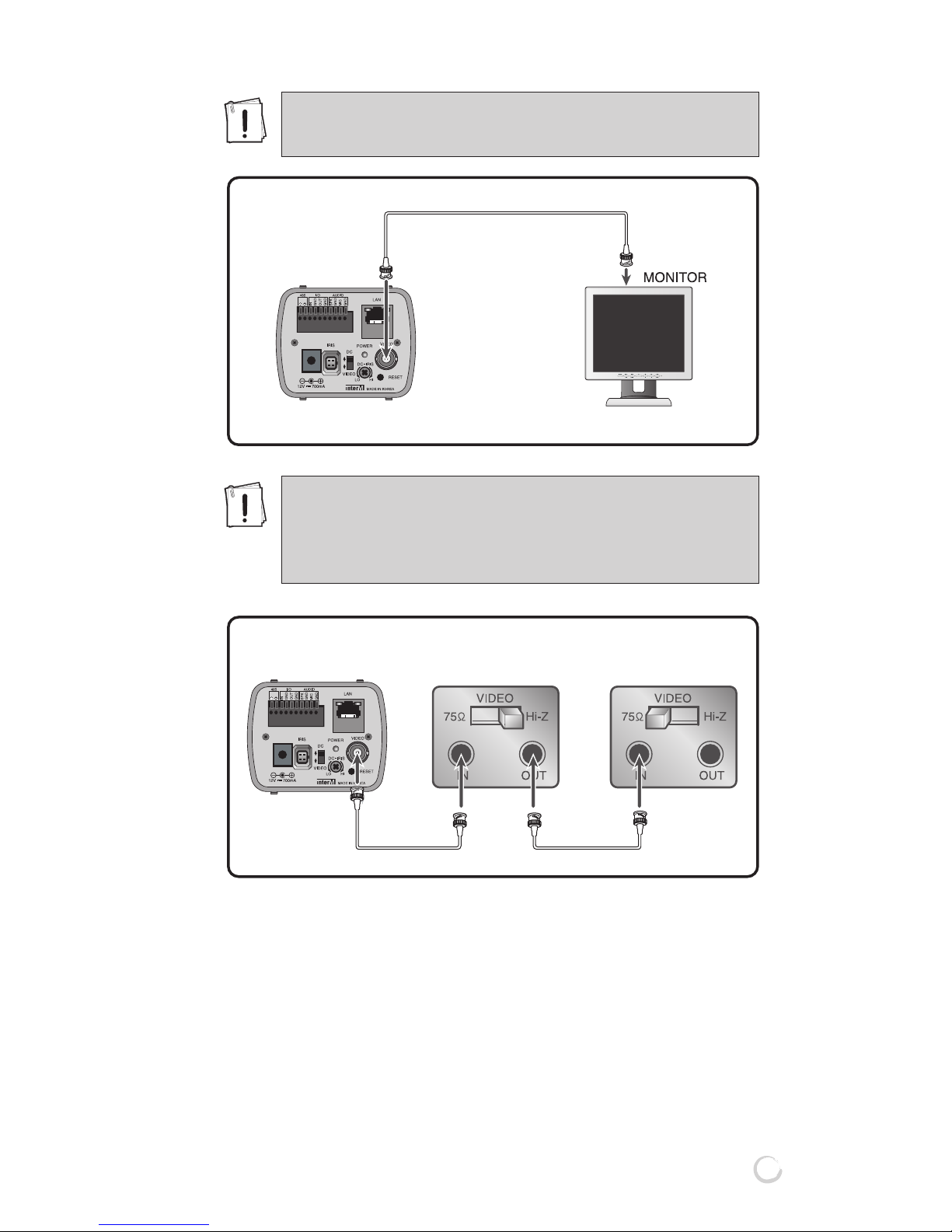
33
33. CONNECTING A MONITOR
■■
■■
METHOD IN CONNECTING A MONITOR
- The connection method may differ depending on the
peripherals connected to a camera. So, refer to the
manuals of individual devices.
- Be sure to disconnect the power supply before making a
connection.
- Connect the 75Ω switch of each peripheral to OFF or HI (not
to be connected to 75Ω end), and connect a monitor to 75Ω.
- For the connection, use a coaxial cable with 75Ω
impedance.
* In case of using a video cable, connect a monitor and the
video output port of a camera with a BNC cable.
Page 25
23
IMN-511/512(HIGH RESOLUTION IP CAMERA)
IMN-511/512 produces the corresponding video signal, If
connected with external device to Video Out(loop through
BNC). The terminal resistance of 75Ω will be automatically
seized by the connection with external device.
* Caution : External surveillance control or monitoring unit
Surveillance control units : Frame Switcher, Quad
Switcher, Sequential Switcher, Multiplexer,
Monitor, etc.
IMN-511/512
IMN-511/512
Be sure to disconnect the power supply before
making connection.
As shown in the figure below, put the 75Ω/Hi-Z
changeover switch to Hi-Z position for the
intermediate video device to 75Ω, for the final video
device.
Intermediate Video Device Final Video Device
Page 26

24
IMN-511/512(HIGH RESOLUTION IP CAMERA)
44
44. CONNECTION METHOD FOR MIC and SPEAKER
(AUDIO Product)
*CAUTION : Connects to Speaker include AMP or lead to AMP
55
55. CONNECTING A NETWORK
HUB or Cable modem
SPEAKER MIC
Page 27

66
66. CONNECTING SENSOR IN/OUT
Alarm sensors and external devices are usable by connecting
to Sensor and Relay terminals of the rear of the IMN-511/512
respectively.
*CAUTION : When connecting an external device to Relay
terminal, you are recommended to use additional
“Relay” for the purpose of the protection of each
device.
25
IMN-511/512(HIGH RESOLUTION IP CAMERA)
Sensor 1
Alarm 1
Sensor Alarm
Page 28

26
IMN-511/512(HIGH RESOLUTION IP CAMERA)
77
77. CONNECTING PAN/TILT
The Serial terminal of the rear side of the IMN-Series uses the
RS-485 interface and PAN/TILT controller can be connected to
the terminal.
The 485+ and 485- of the terminal as shown in picture, is
connected to the external terminal of the PAN/TILT controller,
and generally the external terminal has a +, – polarity indication
so be sure not to switch the polarity.
Refer to the PAN/TILT controller manual and confirm & reset
the following items.
• Baud Rate • Data Bit
• Stop Bit • Parity Bit
• Controller ID (be careful not to duplicate a different controller
ID)
*There must be connected only one PAN/TILT controller.
: RX+
: RXRECEIVER
IMN-SERIES
Page 29

27
IMN-511/512(HIGH RESOLUTION IP CAMERA)
Apply the IP address to the IMN-Series in order to accessible
for the network connection.
* You will need the product’s MAC (Ethernet) address to
complete the IP Setting. The MAC (Ethernet) address may be
found on the unit.
1. Open the Scan Device program by double-clicking the Scan
Device icon ( ) on the Start menu.
2. Select “IP Change” Menu of Mouse Right button Search
device by click the ‘Scan’ button.
3. Setting the product’s IP address, Subnet mask, Gateway
and Host name to apply, click the ‘OK’.
Page 30

28
IMN-511/512(HIGH RESOLUTION IP CAMERA)
4. After the IP setting is finished successfully, click ‘Web
Browser’ to connect to the unit’s Web browser directly.
Then, the web browser of the “Video Streamer Control
Center’’ will open as follow;
* The Network Setup of the Web configuration will be set
with the applied IP address.
5. To finish the network setting completely, enter into the
network setup page by clicking ‘System Setup page’
* By entering the user name, password correctly, you can
login the System setup page
[NOTE] The factory-default user name for the connection is
‘root’ and the password is not.
You can check the detail Web-configuration through
enclosed CD and manual file.
6. In ‘Network Setup’, you must enter the subnet mask and
gateway address to correct to your network environment.
* Please confirm that the all network setting is set correctly.
Page 31

29
IMN-511/512(HIGH RESOLUTION IP CAMERA)
7. Click ‘Set’ button to save the new setting.
[NOTE] 1. The ‘ScanDevice’ program must be executed only at
the PC that is in the local network with the IMN511/512.
2. The ‘ScanDevice’ program have an effect in 10
minutes after booting the IMN-511/512. So if 10 or
more minutes pass after booting without setting a
new IP address, you must reboot it to set a new IP
address.
3. Using 1:1 connection with a PC, you can also set an
IP address to the IMN-511/512. However, the
‘ScanDevice’ program enables you to set an IP
address of the IMN-511/512more easily.
Page 32

30
IMN-511/512(HIGH RESOLUTION IP CAMERA)
① MAC address
A specific Ethernet address assigned to the IMN-511/512 .
② Network media
Select one of Wired or Wireless LAN.(you can used only
Wired.)
③ Host name
Enter the host name to discriminate the system.
④ IP address
- Dynamic IP assignment from DHCP Server : When the
IMN-511/512 use the dynamic IP address assigned from
DHCP Server, check here. (In case of using the cable
modem)
- Manual Setting : When the IMN-511/512 use a static IP
address, check here. Enter the desired network configurations of the IMN-511/512 manually. The IP address that
was already set by the Remote IP Set program will show.
To finish setting network configurations, you must enter
subnet mask, the IP address of a gateway and DNS server
in accordance with your network environment. (Please ask
to your network administrator all about it.)
⑤ SSID
Enter appropriate SSID to connect wireless access point if
you want to connect to IMN-511/512 using wireless LAN.
This value will be ignored if you use wired LAN.
Please confirm that the all network configurations are set
correctly.
Click ‘Set’ button to save the newly configured value.
[NOTE] 1. Please reconnect to the Video Streamer Control
Center using the new IP address after changing the
IP address of the IMN-511/512 .
2. If the IMN-511/512’s network is set with Manual
Setting (Static IP address), you can connect to the
IMN-511/512 remotely with this static IP address
using Video Streamer Control Center or Managing
Station)
Page 33

31
IMN-511/512(HIGH RESOLUTION IP CAMERA)
3. If you use an Internet Gateway (IP Sharer), you must
set virtual server configurations of it to connect the
IMN-511/512 through the Internet Gateway. Please
refer to the manual of the Internet Gateway.
4. If a firewall is installed, the network port used by
IMN-511/512 must be opened to permit the remote
connection via external network. Please ask to your
network administrator all about it.
Page 34
32
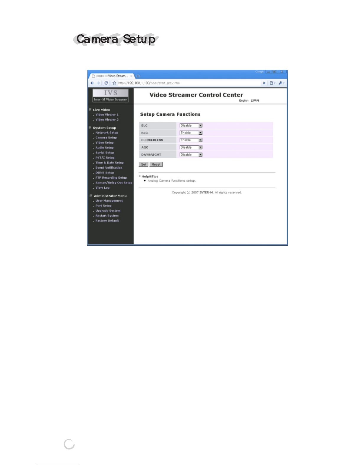
IMN-511/512(HIGH RESOLUTION IP CAMERA)
It configures Camera properties.
① ELC
Enables or disables ELC(ELECTRIC LEVEL CONTROL)
function of the IMN-511/512.
② BLC
Enables or disables BLC(BACK LIGHT COMPENSATION)
function of the IMN-511/512.
③ FLICKERLESS
Enables or disables FLICKERLESS function of the IMN511/512.
④ AGC
Enables or disables AGC(AUTOMATIC GAIN CONTROL)
function of the IMN-511/512.
⑤ DAY & NIGHT
Enables or Fix DAY & NIGHT function of the IMN-511/512.
Page 35

33
IMN-511/512(HIGH RESOLUTION IP CAMERA)
11
11. ELC(ELECTRIC LEVEL CONTROL) FUNCTION
This function automatically controls the light accumulation
time of the CCD image sensor depending on the level of the
light incoming to the camera, and accordingly the shutter
speed is changed to adjust the brightness of the images
automatically. You can use this function when a manual lens
is mounted.
22
22. BLC(BACK LIGHT COMPENSATION) FUNCTION
You can use this function to avoid the phenomenon that
when a bright object is photographed, the surroundings
become darker. This switch improves an image that is
darkened because of backlighting. When the lighting source
is in the rear of an object, the object might be seen
somewhat dark. If you want to see the object clearly, turn this
switch ON.
33
33. FLICKERLESS FUNCTION
When you photograph the lamp which uses the electric
frequency such as a fluorescent light, a flickering may occur.
This is called a flicker. This function is used to remove this
flicker.
44
44. AGC(AUTOMATIC GAIN CONTROL) FUNCTION
This function controls the camera gain automatically by
lowering the signaling level if the amount of incoming light is
much, or increasing the level if little, so as to keep the output
signaling level constant.
* If AGC is OFF, Day&Night function is always fixed color
mode.
Page 36

34
IMN-511/512(HIGH RESOLUTION IP CAMERA)
55
55. DAY&NIGHT / FIX
- Day&Night
IR-CUT filter is automatically pulled out if illumination
intensity becomes low and is changed to B/W. B/W is
converted to IR-CUT filter while converting to color if
illumination intensity becomes high
- FIX
In regardless of illumination, current mode (B/W or COLOR
mode) is fixed.
* In case of ON/OFF of power source, FIX is always color
mode.
* If AGC is OFF, Day&Night function is always fixed color
mode.
Page 37

VIDEO
Image Device 1/3″SONY CCD(410,000 PIXEL)
Signal Type NTSC / PAL (Depends on location)
Horizontal Resolution 540 TV LINE
Min. Illuminance(Color)
0.01LUX(F1.2) IR-CUT FILTER OFF
Lens Control DC IRIS LENS / VIDEO IRIS LENS
Lens C/CS MOUNT LENS
BLC ON / OFF
White Balance ATW / AWB
Day & Night AUTO / FIX
Flickerless ON / OFF
Frame Rate 1 ~ 30FPS
1~60FPS(Dual Stream)
Resolution
NTSC: 720x480, 704x480, 640x480, 352x240, 320x240, 160x120
PAL : 720x576, 704x576, 352x288, 176x144
Compression MPEG-4, MJPEG
Bandwidth
0.256~4 Mbps (Compression: MPEG-4, Resolution: VGA)
AUDIO(Full Duplex)
Input/Output 1 Mic Input / 1 Speaker Output
Compression PCM / ADPCM
RECORD(Network)
Protocol FTP
Schedule
TIME TABLE (Schedule, Motion-detected, Sensor-triggered)
MOTION DETECTION
Method Hardware-based
Detection Area 20x15 Cell Area
TELEMETRY
Sensor Input 1 Input
Sensor Output 1 Output(TTL)
Serial Port RS-485 (Transceiver for PAN/TILT/ZOOM)
35
IMN-511/512(HIGH RESOLUTION IP CAMERA)
IMN-511 IMN-512
Page 38

36
IMN-511/512(HIGH RESOLUTION IP CAMERA)
NETWORK
Media 100Base-Tx
Protocol TCP/IP, UDP/IP, HTTP server, SMTP Client,
DHCP Client, ARP, ICMP
Security Multi-Level Password Protection
Power Source DC 12V
Power Consumption 7.2 Watt 8.4 Watt
Operation Temperature 40~125°F (5~50°C)
Operation Humidity 20~80% RH
Weight 0.5kg
Dimensions 71(W) x 55.4(H) x 158.5(D)mm
MANAGEMENT
Web Browser Viewer, Setup (video, audio, network, time & date,
event, recording, etc.)
Application
SDK support for developing applications(viewer, search, etc.)
Bundle applications: viewer, search, etc.
※ Specifications and design subject to change without notice for improvements.
IMN-511 IMN-512
Page 39
37
IMN-511/512(HIGH RESOLUTION IP CAMERA)
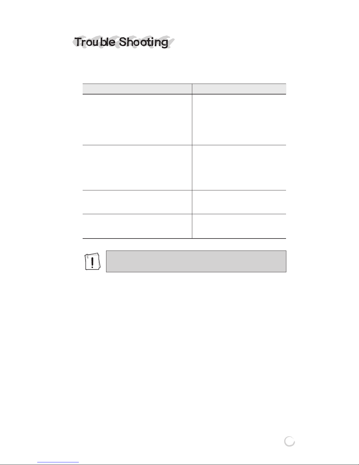
IF YOU HAVE TROUBLE OPERATING IN YOUR CAMERA,
REFER TO THE FOLLOWING.
* White blemish
Cosmic rays or alpha rays affected to the CCD pixel and make
white dot from the CCD surface in the condition of dark.
Problem Solution
NOTHING IS DISPLAYED ON A SCREEN. ★ Check if the power supply is normal.
★ Check if a video signal line is connected
normally.
★ Check that the DC/VIDEO selection
switch on the side of the camra is set
to a proper position according to
the type of your auto iris lens.
SCREEN IS NOT CLEAR. ★ Check if there is dust on a lens.
★ Wipe a lens with clean cloth or brush.
★ Adjust the monitor status.
★ If excessive light is seen on a screen,
change the camera angle or location.
★ Adjust the camera focus again.
SCREEN IS DARK. ★ Adjust the monitor status.
★ Check if the inter-system connection is
normal.
CAMERA OPERATION STATUS IS ABNORMAL. ★ Check if the voltage input to a camera is
ITS SURFACE IS TOO HOT, AND BLACK out of the specifications, or varies from
LINES ARE DISPLAYED ON A SCREEN. time to time.
It may show white blemish in the condition of darkness.
This dot appeared in use by external factors.
Page 40

MADE IN KOREA
www.inter-m.com
November 2008 122887
 Loading...