

Page 1
Operation Manual
20X FULL HD MEGAPIXEL
HD-SDI SPEED DOME CAMERA
HDRC-Z440
Page 2
!
!
"#$! (!%!)!&#!% % "!)$! %#
ll of the co-workers here at Inter-M are dedicated to providing excellent products with inherently
A
good value, and we are delighted you have purchased one of our products.
We sincerely trust this product will provide years of satisfactory service, but if anything is not to your
complete satisfaction, we will endeavor to make things right.
Welcome to Inter-M, and thank you for becoming part of our worldwide extended family!
This symbol is intended to alert the user to the
resence of uninsulated “dangerous voltage” within
CAutION
RISK OF ELECTRIC SHOCK
DO NOT OPEN
CAUTION: TO REDUCE THE RISK OF ELECTRIC SHOCK.
DO NOT REMOVE COVER (OR BACK).
NO USER-SERVICEABLE PARTS INSIDE.
REFER SERVICING TO QUALIFIED SERVICE PERSONNEL.
Caution: To prevent electric shock do not use this (polarized) plug
p
the product’s enclosure that may be of sufficient
magnitude to constitute a risk of electric shock to
ersons.
p
This symbol is intended to alert the user to the
presence of important operation and maintenance
(servicing) instructions in the literature accompanying
the appliance.
with an extension cord, receptacle or other outlet unless
the blades can be fully inserted to prevent blade exposure.
Attentions: Pour prévenir les chocs électriques ne pas utiliser cette
WARNING
To prevent fire or shock hazard, do not
fiche polarisée av ec un prolongateur, une prise de
courant on une autre sortie de courant, sauf si les lames
peuvent étre insérées à fond sans en laisser aucune
partie à découvert.
expose the unit to rain or moisture.
*WARNING FOR YOUR PROTECTION PLEASE READ THE FOLLOWING-WATER AND MOISTURE: Unit should not be used near
water(e.g. near a bathtub, washbowl, kitchen sink, laundry tub, in a wet basement, or near a swimming pool, etc). Care should be taken
so than objects do not fall and liquids are not spilled into the enclosure through openings.
*CLASS 2 WIRING (Adjacent to speaker terminal): The speaker output of this apparatus can exceed 10 Watts and could be a shock injury.
Connection to speakers should be performed by a skilled person.
*Do not install this equipment in a confined space such as a book case or similar unit.
*This apparatus shall not be exposed to dripping or splashing and no objects filled with liquids, such vases, shall be placed on the apparatus.
*This apparatus shall be connected to a mains socket outlet with a protective earthing connection.
It has heed to be easy to disconnect the device. To disconnect the device from power, separate AC input cable from inlet or unplug the AC Cord.
*
CAutION
*These servicing instructions are for use by qualified service personnel only. To reduce the risk of electric shock, do not perform any servicing
other than that contained in the operating instructions unless you are qualified to do so.
NOtE
*This equipment has been tested and found to comply with the limits for a Class A digital device, pursuant to Part 15 of the FCC Rules. These
limits are designed to provide reasonable protection against harmful interference when the equipment is operated in a commercial environment.
This equipment generates, uses, and can radiate radio frequency energy and, if not installed and used in accordance with the instruction manual,
may cause harmful interference to radio communications. Operation of this equipment in a residential area is likely to cause harmful interference
in which case the user will be required to correct the interference at his own expense.
Page 3

"
S3125A
Although your HDRC-Z440 is neither complicated nor difficult to operate, we recommend you take a few
minutes to read this brief manual and familiarize yourself with the important information regarding product
features, setup and operation.
As with most electronic devices, we strongly recommend you retain the original packaging. In the unlikely
event the product must be returned for servicing, the original packaging (or reasonable equivalent) is
required.
$%%!
'#! %
Never place this product in an environment which could alter its performance or reduce its service life.
Such environments usually include high levels of heat, dust, moisture, and vibration.
1. Read these instructions.
2. Keep these instructions.
3. Heed all warnings.
4. Follow all instructions.
5. Do not use this apparatus near water.
6. Clean only with dry cloth.
7. Do not block any ventilation openings. Install in accordance with the manufacturer’s instructions.
8. Do not install near any heat sources such as radiators, heat registers, stoves, or other apparatus (including amplifiers) that produce heat.
9. Do not defeat the safety purpose of the polarized or grounding-type plug. A polarized plug has two
blades with one wider than the other. A grounding type plug has two blades and a third grounding
prong. The wide blade or the third prong are provided for your safety. If the provided plug does not fit
into your outlet, consult an electrician for replacement of the obsolete outlet.
10. Protect the power cord from being walked on or pinched particularly at plugs, convenience receptacles,
and the point where they exit from the apparatus.
11. Only use attachments/accessories specified by the manufacturer.
12. Use only with the cart, stand, tripod, bracket, or table specified by the manufacturer, or sold with the
apparatus. When a cart is used, use caution when moving the cart/apparatus
combination to avoid injury from tip-over.
13. Unplug this apparatus during lightning storms or when unused for long periods of time.
14. Refer all servicing to qualified service personnel. Servicing is required when the
apparatus has been damaged in any way, such as power-supply cord or plug is
damaged, liquid has been spilled or objects have fallen into the apparatus, the
apparatus has been exposed to rain or moisture, does not operate normally, or
has been dropped.
S3125A
Page 4
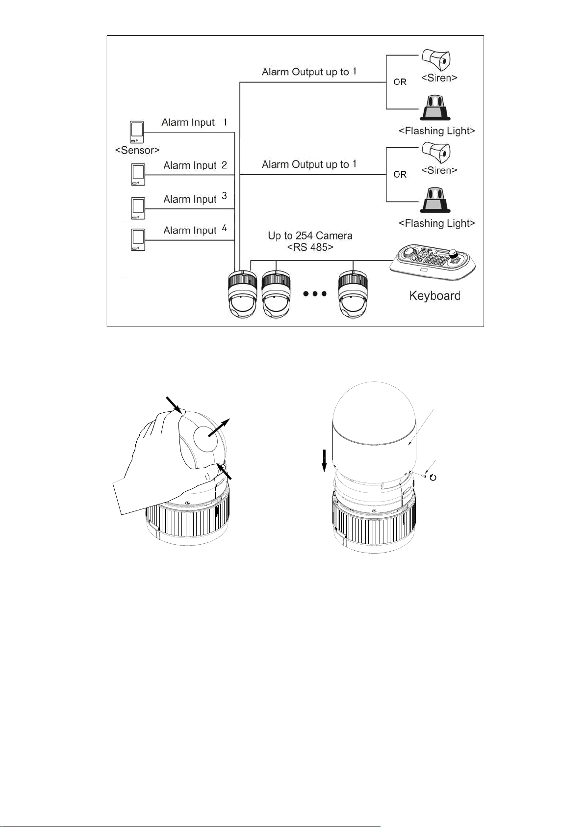
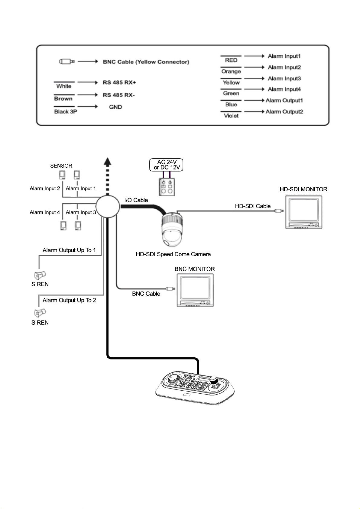
Figure 1 – Typical System Configuration
push
remove window
assemble bubble ring ass'y
push
remove camera window
bubble ring ass'y
screw
Figure 2 –Assemble bubble ring ass’y (Optional)
Note: It is recommended to remove camera window for improving picture quality when you use bubble ring
ass’y.
Page 5
Chapter 2 — Installation and Configuration
2.1 Package Contents
The package contains the following.
HD-SDI Speed Dome Camera ………………………1
Bubble Ring ………………………1(Optional)
Instruction Manual (This Document) ………………………1
Plate Adaptor ………………………1
16 Pin Cable ………………………1
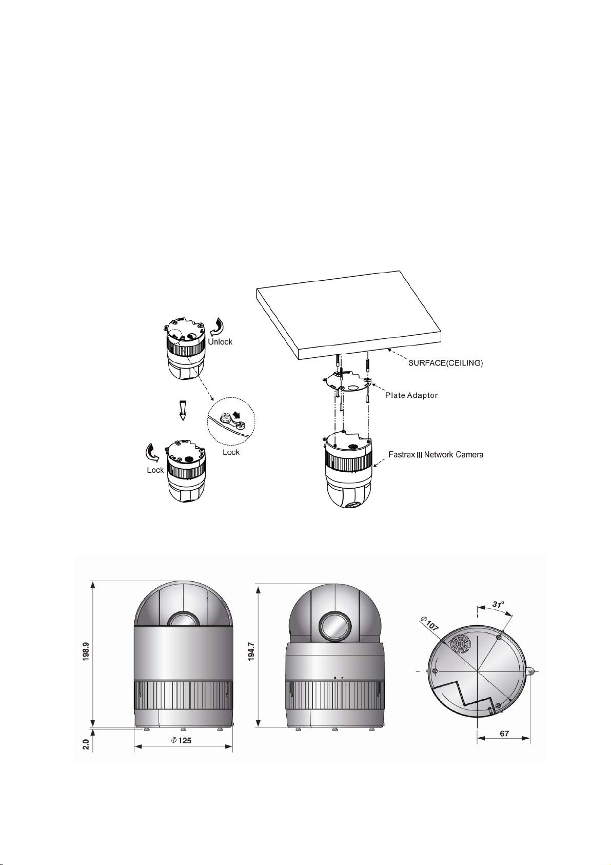
The HD-SDI Speed dome camera is for use in surface mounting applications and the mounting surface
should be capable of supporting loads up to 10lb (4.5kg).
The HD-SDI Speed dome camera ’s base should be attached to a structural object, such as hard wood, wall
stud or ceiling rafter that supports the weight of the HD-SDI Speed dome camera.
Figure 3 – Installation
Figure 4 –Dimension
Page 6
2.2 Basic Configuration of 20x HD-SDI Speed Dome Camera System
Figure 5 – Basic installation diagram
The HD-SDI Speed dome camera must be installed by qualified service personnel in accordance with all
local and federal electrical and building codes. The system should be installed according to Figures 5
through 9.
Page 7
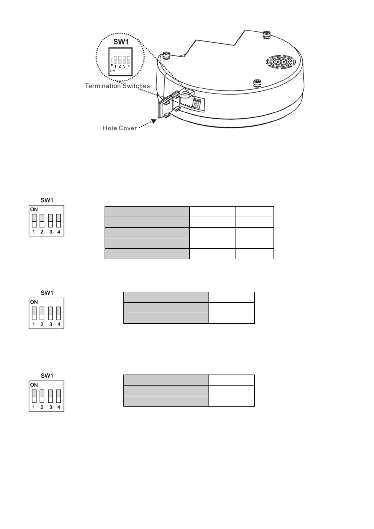
Figure 6 – Layout of Switches
2.3 Setting Dome Camera (Dip Switch)
Figure 7 – One Cable Baud Rate
Figure 8 – Composite Video Signal
Figure 9 – Setting Dome Camera Termination
SW1
1
2
9000bps
ON
ON
10 kbps
ON
OFF
20 kbps
OFF
ON
40 k bps
OFF
OFF
SW1
3
PAL
ON
NTSC
OFF
SW1
4
Terminated
ON
Not Terminated
OFF
Page 8
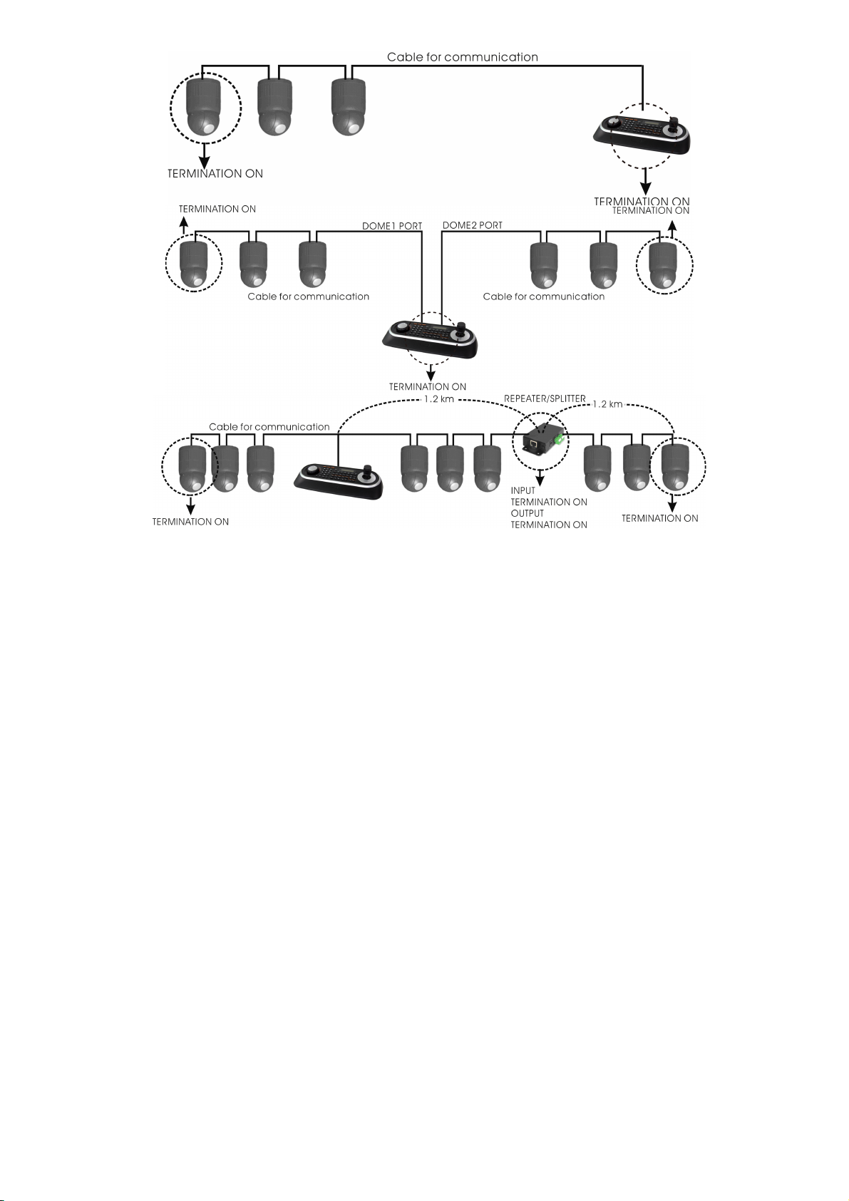
Figure 10 - Termination Diagram
Page 9

2.4 Setting Dome Camera Address (ID)
To prevent damage, each HD-SDI Speed dome camera must have a unique address (ID). When installing
multiple HD-SDI Speed dome cameras using a multiplexer, it is suggested that the dome camera address
match the multiplexer port number.
If you want to set the address more than 3999, you should contact the service provider.
Refer to ‘Dome Configuration – DOME ID’ section for detailed information.
2.5 Setting Dome Camera Protocol
If a dome camera is to be installed with a Fastrax keyboard controller,
select the default protocol.
Consult service personnel if a dome camera is installed with device other than a keyboard controller.
Refer to ‘Dome Configuration – DOME ID’ section for detailed information.
2.6 Connections
• Connecting to the RS485
The HD-SDI Speed dome camera can be controlled remotely by an external device or control system,
such as a control keyboard, using RS485 half-duplex serial communications signals. Connect Marked Rx+,
Rx- to Tx+, Tx- of the RS485 control system.
• Connecting Video out connector
Connect the video out (BNC) / HD-SDI out connector to the monitor or video input.
• Connecting Alarms
AL1 to 4 (Alarm In)
You can use external devices to signal the HD-SDI Speed dome camera to react on events. Mechanical or
electrical switches can be wired to the AL (Alarm In) and GND (Ground) connectors..
GND (Ground)
Connect the ground side of the Alarm input and/or alarm output to the GND connector.
Alarm Output 1 to 2
The HD-SDI Speed dome camera can activate external devices such as buzzers or lights. Connect the device
to the Alarm Out and COM (Common) connectors.
• Connecting the Power
Connect the power of 24VAC or 12VDC to the HD-SDI Speed dome camera.
When using a 12VDC adapter, connector the positive(+) pole to the ‘+’ position and
the negative(-) pole to the ‘-‘ position.
Use satisfy clause 2.5 of IEC60950-1/UL60950-1 or Certified/Listed Class 2 power source only.
Page 10
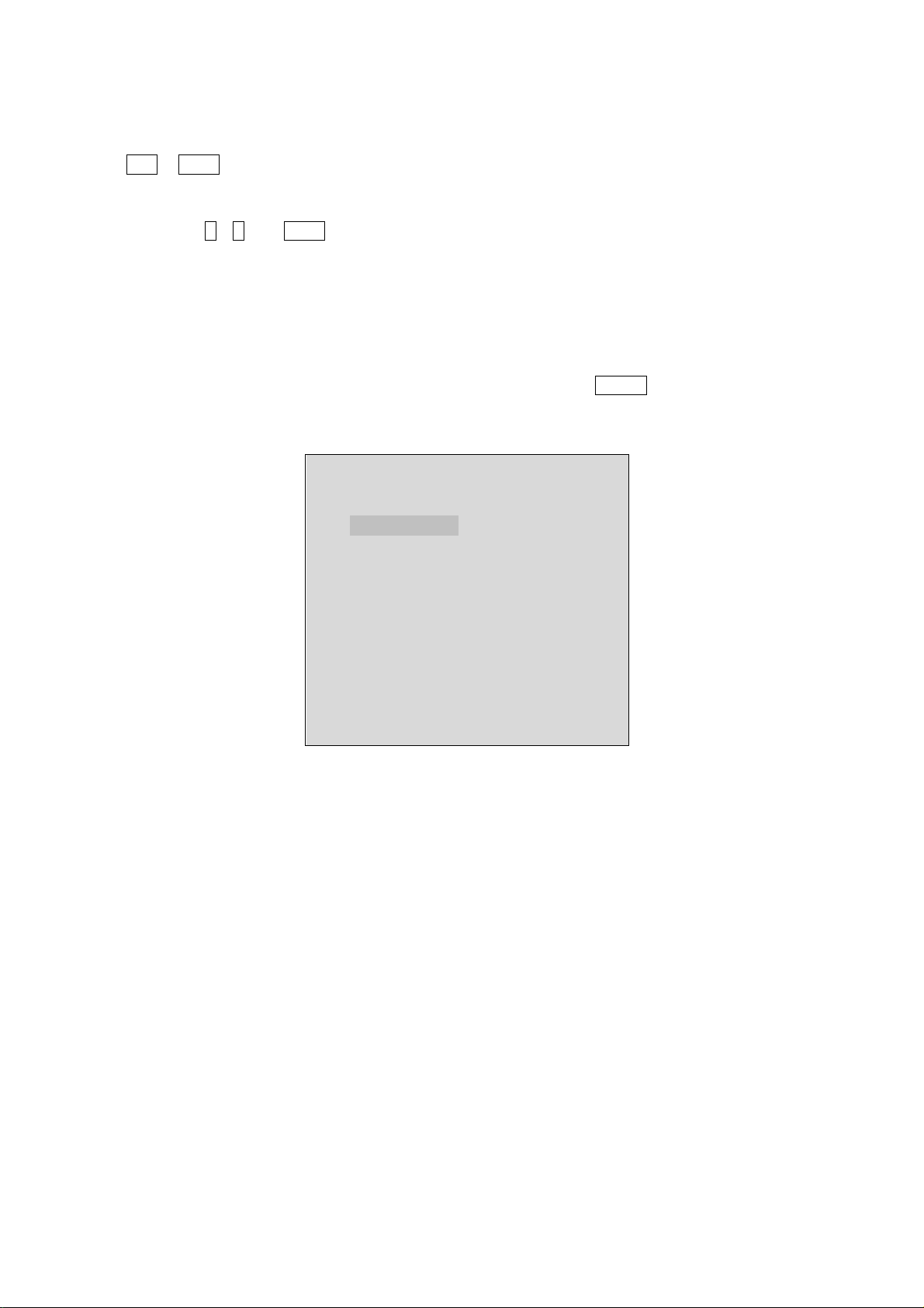
2.7 Getting Started
Once installed apply power to the dome camera. The dome camera will start a configuration sequence.
OSD Position
AF AE
001
EMPTY DATA
DOMEID:0001
360.0,090.0
ALARM:1
INFORMATION
DISPLAY
ALARM DISPLAY
CAMERA TITLE
CAMERA ID
PAN & TILT ANGLE
PRESET TITLE
AREA TITLE
STATUS of
FOCUS and AE
FUNCTION
UNDER RUNNING
Page 11
Chapter 3 — Program and Operation
3.1 Dome Camera Selection
Before you program or operate a dome camera, you must select the dome camera by pressing the dome
camera No. + CAM
Example: Pressing 1 , 0 and CAM key sequentially will select dome camera 10. The selected dome camera
ID will be displayed on the LCD monitor of the keyboard controller.
3.2 Accessing the On-Screen Menu Utility
You can call up the On-screen menu utility on your monitor by pressing MENU key on the keyboard
controller, the following On-screen menu utility will appear:
DOME MENU
AUTO SCAN
PRESET
TOUR
PATTERN
PRIVACY ZONE
CAMERA
DOME COMMUNICATION
ALARM
DOME SETUP
EXIT
Page 12

3.3 How to control the On-Screen Menu Utility
Function
Button
Call the On-screen menu utility
MENU
Navigate through the menu items.
Joystick up or down
Go into the sub-menu items.
Joystick left or right
or IRIS Open
Change value.
Enter the editing title mode.
Joystick left or right or
Zoom handle twist or
Tele , Wide
Change value of angle
CTRL + Joystick
Enter the changing angle mode.
IRIS Open
Exit the changing angle mode.
IRIS Close
Escape (EXIT)
ESC
3.4 Auto Scan (Shortcut: SCAN)
The Auto scan supports up to 17 programmed angles at user-programmable speeds. Follow these steps to
program Auto Scan:
AUTO SCAN SETUP
NUMBER : 01
TITLE : A01
MODE : NORMAL
SPEED : 5 STEP
START ANGLE : ----- ----END ANGLE : ----- ----SCAN DIR : CCW
SWAP : OFF
DWELL : 03 SEC
SAVE AND EXIT
NUMBER :01 -08,
mode
TITLE :up to 12 characters.
MODE :NORMAL, VECTOR, RANDOM (AUTO PAN mode :NORMAL, RANDOM only)
NORMAL: Move from start point to end point in panning only.
VECTOR: Move from start point to end point including tilt and zoom simultaneously and
linearly. In some model, the zoom is fixed at wider angle and the zoom magnification
information is not displayed.
RANDOM: Move randomly between the start point and the end point.
10-17, 09:AUTO PAN
SPEED
SCAN DIR : Set the scan direction, CCW(Counter Clock Wise), CW(Clock Wise)
SWAP : Swap the start point for the end point.
DWELL : Set the dwell time at the both end, 01 – 99 seconds
: 1 - 13 step, the lower number means the slower speed.
Page 13

1.
Press the SCAN key to enter the auto scan menu directly. Or press the MENU key to display the main
menu on the monitor. Scroll to Auto Scan and push the Joystick to the right.
2. Select the” NUMBER” and set the desired number by pushing the Joystick left or right.
3. Select the “TITLE” and twist the Joystick to enter the title edit mode.
4. Twist the Joystick by changing the alphanumeric characters and move the next position. Or move down
to the character table and press CTRL or IRIS OPEN at the desired character then the cursor position
moves to the next position automatically. Push the Joystick left or right at the “ALL DELETE” field to delete
all characters. Push the Joystick left or right at the “EXIT” field to finish title edit menu.
TITLE EDIT MENU
CTRL KEY
A01
$
A B C D E F G H I J
K L M N O P Q R S T
U V W X Y Z 0 1 2 3
4 5 6 7 8 9
ALL DELETE
EXIT (ESC TO EXIT)
5. Select “MODE” and “SPEED”.
6. Select “START ANGLE”. Hold down the CTRL key while selecting the start position using the Joystick.
Current panning position will be displayed. Release CTRL key to complete the selection of the start
position. Or Press IRIS Open then the “CTRL” displays. Move the desired position and the zoom position.
Press IRIS Close then the “CTRL” disappears. To adjust at the 0.1 degree interval, twist the Joystick at the
pan field and the tilt field. To adjust at the one zoom interval, twist the Joystick at the zoom field.
7. Select “END ANGLE.” Hold down the CTRL key while moving the Joystick to select the end position. The
end position angle should be larger than start position. Release the CTRL key to complete the selection of
the end position. Or Press IRIS Open then the “CTRL” displays. Move the desired position and the zoom
position. Press IRIS Close then the “CTRL” disappears. To adjust at the 0.1 degree interval, twist the
Joystick at the pan field and the tilt field. To adjust at the one zoom interval, twist the Joystick at the zoom
field.
8. Set “SCAN DIR” to CCW or CW.
9. Select “SWAP”. Set to ON, to exchange the start angle and the end angle.
10. Set “DWELL TIME”.
11. Select Save and Exit and push the Joystick to the right or press IRIS Open. Press ESC or IRIS Close to
exit the program without saving.
Pressing the HOME key delete stored data at the angle field.
To set the position using the preset position:
a. Before entering the Auto Scan menu, select a preset position as a starting point for
Auto Scan.
Example: 2 + PRST and do step 1 to 4. In step 5, just press the Ctrl key at the start angle position, the
current position will be displayed as a start position.
b. Save and exit from the menu.
c. In normal mode, call a preset to be the end point of scan. Press 3 + PRST then press Scan key to enter
the Auto Scan menu. Move the cursor position to END ANGLE. Just press CTRL key at the end angle
position. Save and exit from the menu.
Page 14

If you need to view specific places routinely, you should program presets. A preset is a programmed video
scene with automatic pan, tilt, zoom, focus, and AE settings. Once programmed, placing the number
position and pressing a PRST button on your controller calls up that preset automatically. In addition, presets
may be assigned to alarm actions or
as the “home” position for the dome camera. As many as 240 presets, whose positions are saved in the
dome’s firmware, may be programmed.
There are three pages of preset menu. Each page has 80 presets. Pages can be scrolled
by pushing the Joystick to the Left or Right on the first or last No. of Preset.
- : blank preset position
$ : position has the preset
! : Current cursor position
Follow steps below to store the Preset positions:
1. Press the PRST key to enter the preset menu directly. Or press the MENU key to display the main menu
on the monitor. Scroll to preset and push the Joystick to the right.
2. Select the blank preset position to be stored by pushing the Joystick up, down, right,
or left.
3. After selecting a blank position, press and hold CTRL,
Use the Joystick to control the direction of the
camera and lens.
4. After aiming the camera (view direction and lens control), release CTRL. The
cursor will be on the Title
then twist the Joystick handle or Press Tele or Wide Key to edit the preset title. Follow the procedure of
the auto scan above to edit titles.
5. Select “CAME
RA SET” and pushing the Joystick left or right. Then the preset camera setup displays.
AUTO SCAN AREA SETUP
PRESET SETUP
NUMBER : 001 CTRL KEY
TITLE : --CAMERA SET
DWELL : --- SEC 1234567890
----------
----------
----------
NEXT PAGE
SAVE AND EXIT
CTRL KEY
NUMBER01
START: ----- ----END : ----- ----EXIT
The setting procedure is the same as above.
NOTE: 09:AUTO-PAN mode(Endless panning)
3.5 Preset (Shortcut: PRST)
Page 15

Press SCAN key on the angle field to display with the small OSD. Then the screen will show as below.
PRESET CAMERA SETUP
FOCUS : AUTO
MOTION : OFF
MOTION SETUP
AE SETUP
SAVE AND EXIT
Set FOCUS: AUTO, MANUAL, ONE PUSH
Set MOTION: OFF, ON
Select “MOTION SETUP” and pushing the Joystick left or right. Then the MOTION setup displays.
MOTION SETUP
SENSITIVITY : 12
POSITION : ALL
DELAY : 00 SEC
OUTPUT : OFF
HOLD TIME : 03 SEC
EXIT
Set SENSITIVITY: 1~15
Set POSITION: ALL, CENTER
Set DELAY: 0~5 SEC
Set OUTPUT: OFF, OUT1, OUT2
Set HOLD TIME: 3~99 SEC
Select “AE SETUP” and pushing the Joystick left or right. Then the AE setup displays. Refer to the AE
SETUP in the camera setup.
6. Set “DWELL TIME”(03-99second)
7. To select the next page of presets, scroll the page by pushing the Joystick to the Left
on the first and last columns of the menu.
8. Repeat steps 2 through 7 for each additional preset position.
9. Select Save and Exit by pushing the Joystick to the right. Press ESC to exit the Preset menu without saving.
NOTE: Press the HOME key at programmed preset position($) to delete a programmed preset view.
The position, which is marked with $, already has the preset view assigned. To review the stored preset,
press PRST key on the $,The camera will show the stored preset scene.
PRESET AREA SETUP
CTRL KEY
NUMBER 001
PAN TILT
000.0 000.0
EXIT
Page 16

Hold down the CTRL key while selecting the desired scene using the Joystick. Current position will be
displayed. Release CTRL key to complete. Or Press IRIS Open then the “CTRL” displays. Move the desired
position and the zoom position. Press IRIS Close then the “CTRL” disappears. Select Exit and push the
Joystick to the right.
3.6 Shortcut of Preset Program
After selecting the desired scene, press No. (1 to 240), and press CTRL and PRST subsequently. The current
view will be stored to the selected preset number if the preset number is empty. If selected preset number is
not empty, “OVER WRITE” message will be displayed on the monitor and select the “OK” and push the
Joystick to the right to overwrite.
Example: 1 , 0 , 1 + CTRL + PRST will store current view as preset No. 101. In this case, focus will be
programmed as Auto, dwell time will be set to 3 second, and the current AE mode will be programmed.
3.7 Tour (SHORTCUT: TOUR)
There are 8 programmable Tours. Each Tour consists of up to 42 Preset positions, Patterns, Scans or other
Tours (second-level). Using second-level tours, it can be expanded to over 300 functions in a single tour.
--- : blank position
SCAN TYPE : NORMAL/ VECTOR
DWELL : 03-99 Sec
003 : Preset (1~240)
A08 : Auto Scan (1~8,10~17)
P01 : Pattern (1~8)
T02 : Tour (1~8)
TOUR SETUP
NUMBER : 01
TITLE : T01
SCAN TYPE : NORMAL
SPEED : 5 STEP
TOUR FUNC
SAVE AND EXIT
TOUR FUNC SETUP
DWELL : -- SEC
003 A08 --- --- ---
--- --- --- --- ---
--- --- P01 --- ---
--- T02 --- --- ---
--- --- --- --- ---
--- --- --- --- ---
--- --- --- --- ---
--- --- --- --- ---
EXIT
Page 17

Follow the steps below to program the Tours:
1. Press MENU to display the main menu on the monitor. Scroll to Tour and push the Joystick to the right
to enter the Tour menu. Or just press the TOUR key on the keyboard.
2. Select the” NUMBER” and set the desired number by pushing the Joystick left or right.
3. Choose a blank position to be programmed by pushing the Joystick up, down, right,
or left.
4. To add
a stored preset, twist the Joystick then the stored preset number displays.
5. To place functions other than preset, press TOUR, PTRN, or SCAN for Tour, Pattern
or Auto Scan respectively.
6. You can also overwrite the programmed number and to remove a stored number from the Tour, press
the HOME key on the stored number, a blank position mark (---) will be displayed.
7. Repeat Step 2 through 5 for each desired position. Each title will be displayed on top
of the line.
8. To edit the title, follow the procedure of the auto scan above to edit titles
9. Select Save and Exit and push the Joystick to the right. Press ESC to exit the program without saving.
You can expand the Tour sequence by calling other programmed tours.
NOTE: The speed applies in the vector mode only.
NOTE: In the Tour mode, in conjunction with preset and Auto Scan, you can make the camera travel from a preset
position to another preset position at a specific speed.
Example: Preset 001>002>003>004>005>006, Auto Scan 01 starts at preset 002, ends at preset 003,
Auto Scan 02 starts at preset 005, ends at preset 006; Tour 001, 002, A01, 004, A02.
1 2 2~3 4 5~6, repeat
where : Quick move, ~ : Programmed speed
To change the dwell time of the preset in the tour:
Use the Joystick to move the cursor to a stored preset position. By pressing PRST key, the camera will move
to the stored Preset view and the cursor moves to the dwell time field. After changing the dwell time, press
PRST key and the cursor moves to the preset number.
To assign the functions other than preset in the tour when the function key is not existed:
Use the Joystick to move the cursor to a stored preset position. Pressing CTRL key or
IRIS OPEN key will change the preset number to other function (auto scan, pattern, tour, preset) with the first
programmed number. To change the number, twist the joystick or press Tele or Wide key.
Page 18

3.8 Pattern (Shortcut: PTRN)
The Pattern feature records user control of the selected dome camera. Up to four 8 patterns can be stored
and played back by pressing No.+ PTRN keys subsequently.
PATTERN SETUP
N TITLE SEC PERCENT
01 : P01 000 00.0
02 : P02 000 00.0
03 : P03 000 00.0
04 : P04 000 00.0
05 : P05 000 00.0
06 : P06 000 00.0
07 : P07 000 00.0
08 : P08 000 00.0
SAVE AND EXIT
Follow steps below to
1. Press MENU to display the main menu on the monitor. Scroll to Pattern and push the Joystick to the
right to enter the pattern menu. Or just press the PTRN key on the keyboard.
2. Select the desired pattern to be programmed by pushing the Joystick Up or Down. If the pattern is not
000, a pattern has already been recorded. Patterns can be overwritten.
3. Press and hold down the CTRL key while controlling the camera direction and zoom with the Joystick.
The dome will be automatically recorded until you release the CTRL key. Or Press IRIS Open then the
“CTRL” displays. Move the position and the zoom position. Press IRIS Close then the “CTRL”
disappears.
4. Select Save and Exit and push the Joystick to the right. Press ESC to exit the program without saving.
5. To edit the title, follow the procedure of the auto scan above to edit titles.
NOTE: Press the HOME key at any programmed position to delete the pattern.
NOTE: If total recording time reaches 500 seconds, it will automatically stop for a moment.
Press PTRN key on the title field to display with the small OSD. Then the screen will show as below.
prog
ram the Pattern:
PATTERN AREA SETUP
CTRL KEY
The setting procedure is the same as above.
NUMBER 01
000 00.0%
0001 01.0%
EXIT
Page 19

3.9 Privacy Zone
Hide up to 12 unwanted scenes in a camera.
PRIVACY ZONE SETUP
N CTRL KEY
01 ON BLOCK BLACK
02 ON BLOCK GRAY
03 ON BLOCK BLACK
04 ON BLOCK BLACK
05 ON BLOCK BLACK
06 ON BLOCK BLACK
NEXT
SAVE AND EXIT
1. Place the cursor at the title field.
2. Holding down the CTRL key displays the privacy area menu while selecting the position using the
Joystick. Current position will be displayed. Release CTRL key to complete the selection of the position.
Or Press IRIS Open then the privacy area menu displays. Move the desired position. Press IRIS Close
then the “CTRL” disappears and returns to the previous menu.
3. Place the cursor at the title fiel
d. Twist the Joystick to enter the title edit mode. Follow the procedure of
the auto scan above to edit titles.
4. To turn the stored zone On or Off, tw
ist the Joystick handle or press Tele or Wide Key.
5. Set the method, “BLACK” or “GRAY”
6. Select the Save and Exit option by pushing the Joy
stick up or down. Save and exit the program by
pushing the Joystick to the right. Press ESC to exit the program without saving.
Press the HOME key to delete programmed privacy zone at the title field.
PRIVACY AREA MENU
CTRL KEY
NUMBER 001
354.8 344.8
EXIT
Page 20

3.10 Camera Menu
CAMERA SETUP
FOCUS CONTROL
WB CONTROL
AE CONTROL
CAMERA CONTROL
SHARPNESS : 10
DIGITAL ZOOM : OFF
IMAGE FLIP : OFF
PRESET FREEZE : OFF
RESOLUTION : 720P/60
SAVE AND EXIT
FOCUS SETUP
MODE : AUTO
SENSITIVITY : NORMAL
FOCUS LIMIT : 1M
SAVE AND EXIT
• FOCUS CONTROL
MODE AUTO / MANUAL / ONE PUSH / CONSTANT MANUAL
Use manual mode in normal use.
SENSITIVITY NORMAL / LOW
NORMAL: Use this option when shooting fast motion.
LOW: Offers better focus stability. In low luminance conditions, Auto Focus stops
operation even when brightness changes, enabling stable images of moving
objects.
FOCUS LIMIT This distance is approximate value and the focus operate from the setting value.
CAUTION: Avoid continuous, 24-hour use of the auto focus. This will shorten the lifespan of the lens.
• WB (White Balance) CONTROL
WB SETUP
MODE : ATW
R GAIN : 213
B GAIN : 174
SAVE AND EXIT
MODE ATW / MANUAL / OUTDOOR AUTO / SODIUM AUTO / SODIUM AUTO /
INDOOR / OUTDOOR
ATW Auto tracing white balance. (2000 to 10000° K)
MANUAL Control of R and B gain
OUTDOOR AUTO Auto mode specifically for outdoors.
SODIUM AUTO Auto mode that is compatible with sodium vapor lamps
SODIUM Fixed mode specifically for sodium vapor lamps
OUTDOOR 5800 K base mode
AUTO Computes the white balance value output using color information
from the entire screen automatically. (3000 to 7500 °K)
INDOOR 3200 K base mode
RGAIN 0 ~ 255
BGAIN 0 ~ 255
RGAIN / BGAIN modes are controllable only in MANUAL Mode
Page 21

• AE CONTROL
“888” + ENTR will turn On the NIGHT SHOT mode.
ON: B/W mode.
OFF: Color mode.
NOTE : Selecting the Night Shot to Auto mode will change AE mode to “AUTO”.
AE SETUP
MODE : MANUAL
SLOW SHUTTER : --IRIS : F1.6
GAIN : 0 DB
BRIGHT : --SHUTTER : 1/60
BACK LIGHT : OFF
WDR : OFF
ADDITIONAL AE
SAVE AND EXIT
MODE
AUTO / MANUAL / IRIS
PRIO / SHUTTER PRIO / BRIGHT
AUTO Auto Iris and Gain, Fixed Shutter speed
(NTSC: 1/60 sec, PAL: 1/50 sec)
MANUAL Variable Shutter, Iris and Gain.
IRIS PRIO Variable Iris, Auto Gain and Shutter speed.
SHUTTER PRIO Variable Shutter speed, Auto Iris and Gain.
BRIGHT Variable Iris and Gain
SLOW SHUTTER ON/OFF
IRIS CLOSE / F14 / F11 / F9.6 / F8.0 / F6.8 / F5.6 / F4.8 / F4.0 / F3.4 / F2.8 /
F2.4 / F2.0 / F1.6
GAIN 0 / 2 / 4 / 6 …… / 28 / -3 DB
BRIGHT 0, 1,2, 3, 4 ..... 25
SHUTTER 1/1 , 1/2 , 1/4(3), 1/8(6). .. 1/4000(3500), 1/6000, 1/10000
BACK LIGHT Objects in front of bright backgrounds will be clearer with BLC ON.
WDR ON,OFF
NOTE: Values in ( ) are for PAL Camera.
NOTE: The Back Light operates in AUTO mode only.
For example, if you change the back light to ON, the camera will change AE mode to “AUTO”.
ADDITIONAL AE SETUP
NIGHT SHOT : OFF
SLOW RESPONSE : 01
HIGH SENS : OFF
EXIT
NIGHT SHOT AUTO,ON,OFF,GLOBAL
The NIGHT SHOT option removes the IR cutoff filter of the camera and makes the camera sensitive to near
infrared.
AUTO Camera goes in to B&W mode at low light.
GLOBAL Controlled by the keyboard.
The operator can enable NIGHT SHOT for all dome cameras at the same time.
If the NIGHT SHOT mode is set to GLOBAL, “999” + ENTR will turn Off the NIGHT SHOT mode and
Page 22

SLOW RESPONSE 1-32
SLOW RESPONSE
The slow response function allows you to lengthen the automatic exposure response speed from 1 up to 32
times. For example, with the normal setting (about 1 second), if the headlights of a car are caught by the
camera, the camera automatically adjusts the exposure so that it can shoot a high-intensity subject (in this
case, the headlights). As a result, images around the headlights, that is, the rest of the subject, except the
headlights, becomes relatively dark, and poorly distinguished. However, using the slow response function
can still easily distinguish the portions of the image surrounding the headlights.
HIGH SENS ON,OFF
• CAMERA CONTROL
CAMERA CONTROL
DNR CONTROL
DN THRESHOLD : 10
BRIGHT OFFSET : 0
GAIN LIMIT : 24 DB
GAMMA : STANDARD
CHROMA : MID
COLOR GAIN : 130
SAVE AND EXIT
DNR CONTROL
DNR CONTROL
DAY DNR : 03
DAY MOVING DNR : 02
NIGHT DNR : 05
NIGHT MOVING DNR : 03
EXIT
DAY DNR : 0~5, DNR filter effect level when pan/tilt stop
DAY MOVING DNR : 0~5, DNR filter effect level when pan/tilt move
NIGHT DNR : 0~5, DNR filter effect level when pan/tilt stop
NIGHT MOVING DNR : 0~5, DNR filter effect level when pan/tilt move
DN THRESHOLD 5, … 18 (default),…, 28
Adjusts the level of light at which the camera automatically switches out of
night mode (B/W) operation.
BRIGHT OFFSET (-7,…,0(default),…7) : Adjust the brightness level
(AUTO, SHUTTER PRIO, IRIS PRIO mode only) .
GAIN LIMIT 4~15, Gain limit in the AE mode
GAMMA STANDARD / STRAIGHT / S-CURVE-LOW / S-CURVE-MID
S-CURVE-HIGH
COLOR GAIN 60 ~ 200
SHARPNESS The higher the value, the more edges in the picture will be enhanced (0~15)
Digital ZOOM OFF : Zoom range is limited to the optical.
2X : Zoom is extendable up to 2X of digital range.
4X : Zoom is extendable up to 4X of digital range.
MAX: Zoom is extendable Max digital zoom range
IMAGE FLIP This function turns the video output from the camera upside down and reverses it
horizontally.
This option is helpful to install in the opposite side.
PRESET FREEZE ON: the image is frozen during calling preset.
RESOLUTION 720P/60fps, 720P/50fps, 720P/30fps, 720p/25fps
1080P/30fps, 1080P/25fps, 1080i/60fps, 1080i/50fps
Page 23

3.11 Dome Communication
DOME ID : Setting the dome camera address (ID) selection (1 ~ 3999)
PROTOCOL : AUTO, Fastrax II / IIE, Pelco-P / D
BAUD RATE : Setting the RS 485 Baud Rate (2400, 4800, 9600, 19200, 38400)
3.12 Alarm Setup
NO : Alarm input number
PRI(Priority) : The lower number has higher priority. (0-8)
FUN(function) : Stored function number to be called by alarm.
IN : X - ignore, ON - Enable
OUT : OUT1 ~ OUT2, OFF - No output.
HLD(HOLD) : Alarm will be held for programmed time (03 to 99 seconds)
LATCH : ON - Shows all alarms including past alarm.
OFF - Shows activated alarms only.
DWELL :Means the dwell time during multiple alarms, 03 to 99 seconds.
The ALARM OUT setup is helpful when the outdoor housing is used with the dome.
Ex.) When you connect the relay output of the dome to the heater connector of the outdoor housing, the
relay output can operate during the setting time only.
DOME COMMUNICATION
DOME ID : 00XX
DOME ID : XX00
PROTOCOL : AUTO
BAUD RATE : 9600
PARITY : NONE
SAVE AND EXIT
ALARM OUT SETUP
OUT1 : ALARM
OUT2 : 1 MIN
EXIT
ALARM SETUP
N P FUN IN O H L
01 1 001 X OFF 03 OFF
02 2 A01 X OFF 03 OFF
03 1 --- X OFF 03 OFF
04 1 --- X OFF 03 OFF
DWELL : 03
ALARM OUT SETUP
SAVE AND EXIT
Page 24

ALARM: The alarm output is operated during an alarm operation or by the short key of our keyboard.
1-5 MIN(minute): The alarm output is operated during this setting time only by the function run of
the dome menu or the short key of our keyboard.
NOTE: This 1-5 MIN setting is not operated by an alarm.
There are 9 levels of priority. The function can be selected by Preset, Auto scan, Pattern or Tour and “0” is
the highest priority. Lower priority alarms won’t be serviced until the higher priority alarm is completed.
Equal priority alarms will be serviced repeatedly with the dwell time.
3.13 Dome Setup
• HOME FUNCTION SETUP
HOME FUNCTION : None/ Tour/ Pattern / Auto Scan / Preset
FUNCTION NUMBER : - - WAITING TIME : 10~240 Seconds
FUNCTION ENABLE : ON/ OFF
The Home function can be set so that the camera automatically goes to Preset, Tour, Pattern, Auto Scan after
the keyboard controller has been idle for a amount of time. For example, if the controller is idle for 120
seconds, the camera goes to preset 1.
Follow these steps to program the Home position:
1. Select Home Function by pushing the Joystick to the right or to the left to scroll through the None, Tour,
Pattern, Auto Scan or Preset functions.
2. Select Function Number and push the Jo
ystick to the right or to the left. The recorded function number
will scroll.
3. Select WA
TING Time and push the Joystick to the right or to the left to select from 10 to 240 seconds.
4. Select Function Enable and turn to ON or OFF by pushing the Joystick to the right or to the left.
CONFIGURATION MENU
HOME FUNCTION SETUP
VIEW ANGLE SETUP
ORIGIN OFFSET
FACTORY DEFAULT
DOME RESET
OSD DISPLAY
SYSTEM SETUP
FUNCTION RUN
SYSTEM INFORMATION
EXIT
HOME FUNCTION SETUP
FUNCTION : NONE
NUMBER : --WATING TIME : 120 SEC
ENABLE : OFF
SAVE AND EXIT
Page 25

• VIEW ANGLE SETUP
VIEW ANGLE SETUP
PANNING RANGE
FLIP : 90°
TILT OVER : ON
SAVE AND EXIT
IP: OFF,90°,100°,110°,120°,AUTO
FL
OFF: the dome camera moves until 90° vertically.
90°, 100°, 110°, 120°: allows the image to flip digitally when the camera moves over the setting
angle vertically.
AUTO: When the camera reaches the floor directly above the moving object, it will stop. At that time,
release the Joystick handle instantly and pull it down again to run the auto-flip function. When you use
the panning range, we recommend using the flip mode to AUTO.
TILT OVER ANGLE:
This option is used to set the limit of the horizontal view angle so that the trim ring or ceiling does not
obstruct the horizontal image when zooming out (wide angle).
ON: In some installations it is desirable for the dome camera to be able to see above the horizon.
When this option is chosen, the dome will tilt up over the horizon (About -10 degrees). When the lens is
zoomed out, you can see the ceiling line. But when the lens is zoomed in, the viewing angle is
narrower, and the ceiling line disappears.
Without Bubble: The tilt range of the camera is limited to see the horizon so the picture shows part of
the ceiling line.
With Bubble: The tilt range of the camera is limited to see below the horizon
(10 degrees).
Over Angle is not sufficient enough to avoid ceiling obstructions, please adjust Origin Offset of tilt
angle as described below.
• ORIGIN OFFSET
OFFSET SETUP
CTRL KEY
PAN OFFSET : 000.0
TILT OFFSET : 000.0
ENABLE : OFF
SAVE AND EXIT
This feature is useful to align a new dome camera exactly the same as the previously installed dome camera.
Dome camera’s origin set and all data initialize option do not override offset values. Only the default set
option in this menu will set the offset value to zero. This can be used to avoid ceiling obstructions.
Page 26

• FACTORY DEFAULT
Select the Factory Default to initialize the Data.
• DOME RESET
calibrate the orientation
of a selected dome camera. Origin offset value is not affected by this function. (Offset is still valid after
origin set)
• OSD DISPLAY
TITLE : up to 6 characters.
DOME OSD : ON / OFF
All display or title will disappear when DOME OSD DISPLAY sets OFF
FOCUSE EXPOSURE : ON / OFF
ON: FOCUS and EXPOSURE displays. (AF AE)
• SYSTEM SETUP
FACTORY DEFAULT
ARE YOU SURE ?
CANCEL
OK
OSD DISPLAY SETUP
TITLE : DOMEID
DOME OSD : ON
FOCUS EXPOSURE : ON
SAVE AND EXIT
SYSTEM MENU
MOTOR SETUP
ORIGIN CHECK
CALIBRATION : ON
MENU TIME OUT : OFF
DOME ANSWER : ON
PST FOCUS : AUTO
SAVE AND EXIT
This feature is used to re
DOME RESET
ARE YOU SURE ?
CANCEL
OK
Page 27

CALIBRATION : ON (Auto origin check) / OFF
MENU TIME OUT : ON(5mintues) / OFF( always menu display)
DOME ANSWER ; ON / OFF(no acknowledge command from the dome) This option is helpful
to escape the collision of the command using some DVR.
PST FOCUS : Set the default mode of the focus when you save the preset
(AUTO / MANUAL / ONE PUSH)
MOTOR SETUP
Motor Setup menu provides the pan and tilt speed of a camera. User can set the desired speed with twist
the Joystick left or right. During operation, pressing 153 + ON will change the speed to the SLOW mode
and pressing 153 + OFF will change the speed to the Normal mode.
Holding and pressing CTRL and moving the joystick will operate with the TURBO speed mode.
PROPOTIONAL P/T : ON / OFF
P/T MODE : SLOW / NORMAL / TURBO
SLOW PAN MAXIMUM : 19˚- 90˚/second
SLOW TILT MAXIMUM : 19˚- 90˚/ second
NORMAL PAN MAXIMUM : 40˚- 360˚/second
NORMAL TILT MAXIMUM : 40˚- 200˚/second
TURBO PAN MAXIMUM : 200˚- 380˚/second
TURBO TILT MAXIMUM : 90˚- 300˚/second
ORIGIN CHECK
When you find the wrong position of the dome during operation, execute this origin check and the dome
camera will arrange the right position after the origin check operation.
Pressing 151 + ON will execute the origin check.
ORIGIN CHECK
ARE YOU SURE ?
CANCEL
OK
MOTOR SETUP
PROPOTIONAL PT : ON
PT MODE : NORMAL
SLOW PAN MAX : 40°/SEC
SLOW TILT MAX : 40°/SEC
NORMAL PAN MAX : 90°/SEC
NORMAL TILT MAX : 90°/SEC
TURBO PAN MAX : 360°/SEC
TURBO TILT MAX : 100°/SEC
SAVE AND EXIT
Page 28

•
Function Run
This Function Run menu allows you to execute the function when you use a keyboard or a DVR without the
function keys (Preset, Pattern, Tour and scan).
1. Select the desire
d Function by
pushing
Joystick Up or Down.
2. Select the number by twist the Joystick in PRESET,PATTERN,TOUR, and SCAN.
3. Press CTRL or IRIS Open to execute.
Note: To execute the function, you should save the function (PRESET, PATTERN, TOUR, and SCAN) first.
- HOME
Select the HOME menu and press CTRL key. Then dome camera goes to the default position to which the
dome camera returns after an assigned period of inactivity passes.
The default position may be a Preset, Tour, Pattern or no action.
- AUTO PAN
You can execute the endless auto pan which is to turn one direction continuously by select the Auto Pan.
- ALARM OUT
This function can operate only when the alarm output setup has the time in the alarm menu.
Ex)
You can select OUT2 and press CTRL or IRIS Open then that relay operates during the setting time only.
FUNCTION RUN SETUP
CTRL KEY
PRESET : --PATTERN : --TOUR : --SCAN : --HOME
AUTO PAN
ALARM OUT : ---
EXIT
ALARM OUT SETUP
OUT1 : ALARM
OUT2 : 1 MIN
EXIT
Page 29

Appendix A — Specifications
20X Full HD Mega Pixel HD-SDI Speed Dome Camera
MODEL 20X
MODULE
Image Type CMOS Sensor
Image Device 1/2.8 Inch
Image Readout Progressive Scan
Optical / Digital Zoom 20x / 12x
1280 x 720P / 60fps, 50fps, 30fps, 25fps
Resolution
Focal length 4.7mm ~ 94.0mm
Angle of view
White Balance Range 2500°K ~ 9600°K
Min. Illumination
- Day Mode (Color) 1.7 Lux
1980 x 1080P / 30fps, 25fps
1980 x 1080i/ 60fps, 50fps
4.7mm - 55.4°(H)
94.0mm - 2.9°(H)
- Night Mode (B/W) 0.26 Lux
Motion Detection(in PRESET) YES
DOME
Tilt angle -10° ~ 190° (Digital Flip)
Image Flip YES
Auto Calibration 0.1° ~ 6°
Panning angle 360 continuous rotation
Alarm 4 inputs / 2 outputs
Auto Scan 1 auto pan & 16 auto scans capability
Preset 240 presets with individual camera AE setup
Pattern 8 patterns (recording up to 500 sec)
Tour 8 tours (consist of 40 functions/1tour)
Max Speed 380° /sec
Privacy Zone 12 privacy zone masking
* Specifications are subject to change without notice *
Page 30

Electrical
Figure 11 – Dimension
Input Voltage 24VAC / 12VDC ± 10%
Power Consumption 18W (1.5A)
Control
RS-485 baud rate: 2400~38.4k bps
(default: 9600bps)
ID (Camera Address) 3999
Mechanical
Dimension See Figure below
Weight Approx 1.2 kg
Pan Angle
Speed
360° continuous rotation
0.1° to 380°/sec. (proportional to zoom)
380°/sec. maximum (with CTRL key pressed)
Preset Speed: 380°/sec
Flip
180° Digital Flip or 90° Auto Flip.
Autoscan 16 auto scans and one endless panning
Preset Position 240 positions with camera status (6-character title)
Tour 8 tours
Pattern 8 patterns, up to 500 second
Privacy Zone 12 Privacy Zones
On-Screen Display Displays camera ID and Pan & Tilt Angle
Environment
Operating temperature
0°C to 50°C (32°F to 122°F)
Operating humidity 0 to 90%RH (non-condensing)
Storage temperature
-20°C to 60°C (4°F to 140°F)
Page 31

Appendix B — Glossary
ALARM ACTIONS
The assigned responses for the dome camera when inputs change from normal to abnormal states. The
dome may run a Preset, Pattern, or have no assigned action for each of the four dome inputs. The dome
may also send alarm states to the host controller for processing. See also Input and Normal Input State.
AUTOMATIC GAIN CONTROL (AGC)
Allows for the amplification of the video signal in scenes with minimal ambient light. Many low-light scenes
result in picture noise. As gain is increased, the picture noise is also amplified. When AGC is enabled, the
value of the gain setting is based on feedback from the camera. When AGC is disabled, the camera uses
the value set for the manual gain setting. The trade-off between picture level and noise may be adjusted
when AGC is disabled.
FLIP
Allows the dome to automatically turn 180 degrees when the camera tilts to its lower limit and stays in that
position for a brief delay. When the dome flips (rotates), the camera starts moving upward as long as the tilt
control is kept in the down position. Once the control is released, the tilt control returns to its normal
operational mode. The flip feature is useful when you need to track someone who walks directly beneath the
dome and continues on the other side.
HOME POSITION
The default position to which the dome camera returns after an assigned period of inactivity passes. The
default position may be a Preset, Tour, Pattern, or No Action.
INPUT ALARM
A connection point on the dome camera that enables the system to monitor Input Devices. There are four
inputs available for the dome camera.
INPUT DEVICES
External devices that provide information about the condition of system components that connect to the
inputs on the dome camera. Typical input devices include door contacts, motion detectors and smoke
detectors.
IR MODE
A feature of the camera that permits manual or automatic switching between color and IR
(black-and-white) operation. When IR mode is active, clearer images may be obtained under
low-light conditions.
NAME INFORMATION
Relates to the display the dome name, the area where the dome is pointing, the name of the preset or
pattern that is running, and alarm names. The display of each type of name setting can be enabled or
disabled. When the display of camera or area title(name) is enabled, the information appears on the screen
continuously. Preset, tour and pattern titles(names) appear only while they are active.
NORMAL INPUT STATE
Describes the expected state of a device connected to one of eight dome camera’s inputs. The normal state
may be open or closed. When a device is not in its normal input state, an alarm is issued.
Page 32

SLOW SHUTTER
Setting used to improve the quality of video obtained in extreme low-light situations. When the Low Shutter
setting is enabled, low-light information is collected over multiple fields based on the Shutter Limit setting. As
a result, video may appear blurred or choppy in extreme low-light situations. This setting does not effect
camera operation in normal lighting situations.
PATTERN
A series of pan, tilt, zoom and focus movements from a single programmable dome. Up to 8 patterns may
be programmed for the dome camera.
PRESET
Programmed video scene, based on a specific pan, tilt, zoom, and focus settings. Up to 240 presets may be
programmed for the dome camera.
PRIVACY ZONES
Masked areas of the dome camera's viewing area. These masks prevent operators of the surveillance system
from viewing these designated zones. The Privacy Zones move in relation to the dome camera’s pan/tilt
position. In addition, the apparent size of the Privacy Zone adjusts automatically as the lens zooms in or out.
Up to eight Privacy Zones may be established for a dome camera.
SHUTTER LIMIT
Setting used to define the maximum exposure time for the Open Shutter setting. The values for the setting
range from 1/2 to 1/60. The default setting is 1/4.
VECTOR SCAN
Move from start point to end point including tilt and zoom simultaneously and linearly.
WHITE BALANCE
Adjustments in the color hue(red and blue) gains for a camera so that true white appears white in the image.
It is normally compensated for by the automatic gain control. In some lighting conditions, you may need to
manually adjust the red and blue settings for optimal viewing. When Automatic White Balance is enabled,
the camera measures the image and automatically adjusts the red and blue settings to balance white. When
Automatic White Balance is disabled, the camera uses the values set for the red and blue settings to
balance white.
Page 33

Appendix C — Short Cut Key
Short Cut Key
Function
PRST
Pop up preset setup menu.
TOUR
Pop up Tour setup menu.
PTRN
Pop up Pattern setup menu.
SCAN
Pop up Auto Scan setup menu.
NO.+ CTRL + PRST
Store the current view at the selected number.
Short Cut Key
Function
Short Cut Key
Function
1 + ON
Turn On Relay 1.
1 + OFF
Turn Off Relay.
2 + ON
Turn On Relay 2.
2 + OFF
Turn Off Relay.
7 + ON
Change FOCUS to AUTO
7 + OFF
Change FOCUS to
manual
8 + ON
Change AE to AUTO
8 + OFF
Change AE to manual
9 + ON
Change Night Shot to AUTO
10 + ON
Night Shot on (go to the
manual mode)
10 + OFF
Night Shot off (go to the
manual mode)
11 + ON
BLC on (AE auto mode)
11 + OFF
BLC off (AE auto mode)
12 + ON
Digital Zoom on (According
to digital zoom setting)
12 + OFF
Digital Zoom off
13 + ON
Dome OSD on
13 + OFF
Dome OSD off
14 + ON
Dome Area Title Display on
14 + OFF
Dome Area Title Display
off
100 + ON
Shutter speed auto
101 + ON
Shutter speed 1/4(PAL 1/3)sec
102 + ON
Shutter speed 1/2 sec
103 + ON
Shutter speed 1 sec
150 + ON
Image Flip ON
150 + OFF
Image Flip off
151 + ON
Origin Check
152 + ON
Place the camera in the 0° area horizontally.
153 + ON
Go to the slow speed mode
153 + OFF
Go to the normal speed
mode
154 + ON
Display System Information
155 + ON
Flip the camera in the 180° area horizontally.
250 + PRESET
Set the dome ID up to 3999
888 + ENTER
Night Shot on (in the global mode only)
999 + ENTER
Night Shot off (in the global mode only)
* Some function may not operate according to the model.
Page 34

- MEMO -
Page 35

#'
#'
#!&#$
Take steps to insure the problem is not related to operator error or other products within the system.
Information provided in the troubleshooting portion of this manual may help with this process. Once it is
certain that the problem is related to the product contact your warranty provider as described in the warranty
ection of this manual.
s
%
A Schematic is available by contacting your warranty provider.
#%$$%
A Parts List is available by contacting your warranty provider.
#%! $ "%! $
#%! $ "%! $
#%! $
Products supplied through legitimate sources are compatible with local AC power requirements.
"%! $
No optional items are available for this product.
## %)
## %)
Warranty terms and conditions vary by country and may not be the same for all products. Terms and
conditions of warranty for a given product may be determined first by locating the appropriate country
which the product was purchased in, then by locating the product type.
To obtain specific warranty information and available service locations contact Inter-M directly or the
authorized Inter-M Distributor for your specific country or region.
Page 36

Inter-M, Ltd. (Korea) began operations in 1983.
Since then, Inter-M has grown to become one of the largest manufacturers
of professional audio and commercial sound electronics equipment in the world.
Inter-M has gained worldwide recognition for its own branded products,
as well as private label manufacturing of electronics sold under other names (OEM).
The company is no longer just a Korean company, but rather a global company
that is truly international in scope, with factories and offices in Korea and China,
and sales and marketing operations located in Japan, Europe, and the U.S.A.
With more than 850 employees around the globe,
Inter-M is well-poised for further growth and expansion.
%##$
13875 ARTESIA BLVD. CERRITOS, CA 90703 USA
TEL : +1-562-921-0313, FAX : +1-562-921-0370
Home Page : http://www.inter-m.net, E-mail : info@inter-m.net
%#!#"!#%!
SEOUL OFFICE:653-5 BANGHAK-DONG, DOBONG-GU, SEOUL, KOREA
TEL : +82-2-2289-8140~8, FAX : +82-2-2289-8149
Home Page : http://www.inter-m.com, E-mail : overseas@inter-m.com
MADE IN KOREA
August 2013
 Loading...