

Page 1
Operation Manual
Video Audio Matrix Switcher
HDMS-0808
* Rack mount products in the Western Hemisphere(North America, South America,
and the Caribbean) do not have handles installed due to customer preference.
Page 2
VIDEO AUDIO MATRIX SWITCHER
Welcome
Welcome
A personal welcome to you from the management and employees of Inter-M
All of the co-workers here at Inter-M are dedicated to providing excellent products with inherently good value,
and we are delighted you have purchased one of our products.
We sincerely trust this product will provide years of satisfactory service, but if anything is not to your complete
satisfaction, we will endeavor to make things right.
Welcome to Inter-M, and thank you for becoming part of our worldwide extended family!
This symbol is int ended to ale rt the user to the
CAutION
RISK OF ELECTRIC SHOCK
DO NOT OPEN
CAUTION: TO REDUCE THE RISK OF ELECTRIC SHOCK.
DO NOT REMOVE COVER (OR BACK).
NO USER-SERVICEABLE PARTS INSIDE.
REFER SERVICING TO QUALIFIED SERVICE PERSONNEL.
Caution: To prevent electric shock do not use this (polarized) plug with
Attentions: Pour prévenir les chocs électriques ne pas utiliser cette
WARNING
To prevent fire or shock hazard, do not
expose the unit to rain or moisture.
*WARNING FOR YOUR PROTECTION PLEASE READ THE FOLLOWING-WATER AND MOISTURE: Unit should not be used near water(e.g.
near a bathtub, washbowl, kitchen sink, laundry tub, in a wet basement, or near a swimming pool, etc). Care should be taken so than objects do
not fall and liquids are not spilled into the enclosure through openings.
*Do not install this equipment in a confined space such as a book case or similar unit.
*This apparatus shall not be exposed to dripping or splashing and no objects filled with liquids, such vases, shall be placed on the apparatus.
*This apparatus shall be connected to a mains socket outlet with a protective earthing connection.
It has heed to be easy to disconnect the device. To disconnect the device from power, separate AC input cable from inlet or unplug the AC Cord.
*
CAutION
*These servicing instructions are for use by qualified service personnel only. To reduce the risk of electric shock, do not perform any servicing
other than that contained in the operating instructions unless you are qualified to do so.
NOtE
*This equipment has been tested and found to comply with the limits for a Class A digital device, pursuant to Part 15 of the FCC Rules. These limits are
designed to provide reasonable protection against harmful interference when the equipment is operated in a commercial environment. This equipment
generates, uses, and can radiate radio frequency energy and, if not installed and used in accordance with the instruction manual, may cause harmful
interference to radio communications. Operation of this equipment in a residential area is likely to cause harmful interference in which case the user will
be required to correct the interference at his own expense.
presence of uninsulated “dangerous voltage” within
the product’s enclosur e that ma y be of sufficient
magnitude to constitute a risk of electric shock to
persons.
This symbol is int ended to ale rt the user to the
presence of important operation and maintenance
(servicing) instructions in the literature accompanying
the appliance.
an extension cord, receptacle or other outlet unless the blades
can be fully inserted to prevent blade exposure.
fiche polarisée avec un prolongateur, une prise de courant
on une autre sortie de courant, sauf si les lames peuvent
étre inséré es à fond sans en lai sser aucune par tie à
découvert.
Page 3

VIDEO AUDIO MATRIX SWITCHER
Contents
Contents
Unpacking .......................................................................................................................................2
Installation
Environment....................................................................................................................................2
Important Safety Instructions.............................................................................................................2
Summary.........................................................................................................................................3
Features............................................................................................................................................3
Front Panel ......................................................................................................................................4
Rear Panel .......................................................................................................................................6
RS-232C Control.............................................................................................................................8
How to use ......................................................................................................................................8
How to connect...............................................................................................................................9
Applications ..................................................................................................................................12
Block Diagram ..............................................................................................................................13
Specifications ................................................................................................................................14
How to setup MASTER-SLAVE.....................................................................................................16
How to connect a DC adapter to the device............................................................................16
Service............................................................................................................................................19
Variations and Options ...............................................................................................................19
Warranty .......................................................................................................................................19
HDMS-0808
1
Page 4

VIDEO AUDIO MATRIX SWITCHER
S
3125A
Unpacking
Unpacking
Although your HDMS-0808 is neither complicated nor difficult to operate, we recommend you take a few
minutes to read this brief manual and familiarize yourself with the important information regarding product
features, setup and operation.
As with most electronic devices, we strongly recommend you to retain the original packaging. In the unlikely
event the product must be returned for servicing, the original packaging (or reasonable equivalent) is required.
Installation
Installation
Environment
Never place this product in an environment which could alter its performance or reduce its service life. Such
environments usually include high levels of heat, dust, moisture, and vibration.
IMPORTANT SAFETY INSTRUCTIONS
1. Read these instructions.
2. Keep these instructions.
3. Heed all warnings.
4. Follow all instructions.
5. Do not use this apparatus near water.
6. Clean only with dry cloth.
7. Do not block any ventilation openings. Install in accordance with the manufacturer’s instructions.
8. Do not install near any heat sources such as radiators, heat registers, stoves, or other apparatus (including
amplifiers) that produce heat.
9. Do not defeat the safety purpose of the polarized or grounding-type plug. A polarized plug has two blades
with one wider than the other. A grounding type plug has two blades and a third grounding prong. The wide
blade or the third prong are provided for your safety. If the provided plug does not fit into your outlet, consult
an electrician for replacement of the obsolete outlet.
10. Protect the power cord from being walked on or pinched particularly at plugs, convenience receptacles, and
the point where they exit from the apparatus.
11. Only use attachments/accessories specified by the manufacturer.
12. Use only with the cart, stand, tripod, bracket, or table specified by the manufacturer, or sold with the apparatus.
When a cart is used, use caution when moving the cart/apparatus combination to avoid injury from tip-over.
13. Unplug this apparatus during lightning storms or when unused for long periods of time.
14. Refer all servicing to qualified service personnel. Servicing is required when the apparatus has been
damaged in any way, such as power-supply cord or plug is damaged, liquid has
been spilled or objects have fallen into the apparatus, the apparatus has been
exposed to rain or moisture, does not operate normally, or has been dropped.
S3125A
2
HDMS-0808
Page 5

VIDEO AUDIO MATRIX SWITCHER
Summary
Summary
HDMS-0808 is FULL HD VIDEO and STEREO AUDIO MATRIX SWITCHER which can display 8 A/V inputs to 8
random outputs without deteriorations of picture and sound qualities.
It uses the direct switch controlling method for easy controls, and it is designed that controlled content is
displayed on the front display, so you can see it without any difficulty.
Because it has the RS-232C function, it can be controlled in PC, etc., and it can control two of these devices
connected in parallel in a same time.
Features
Features
Features
- 8x8 A/V Matrix Switcher.
- Simple real-time output and DISCONNECTION function.
- Individual or real time control function for audio, video.
- Very low crosstalk and broad frequency response.
- Parallel connection.
- RS-232 function.
- Blackout compensation function which returns to right-before black out status.
- Vertical interval switching between GENLOCKed sources.
- LOCK function to prevent human error.
- Supporting resolution
SD class: 480i, 480p
HD class: 720i, 720p
Full HD class: 1080i
HDMS-0808
3
Page 6

VIDEO AUDIO MATRIX SWITCHER
1
6
2
4
5
3
Front Panel
Front Panel
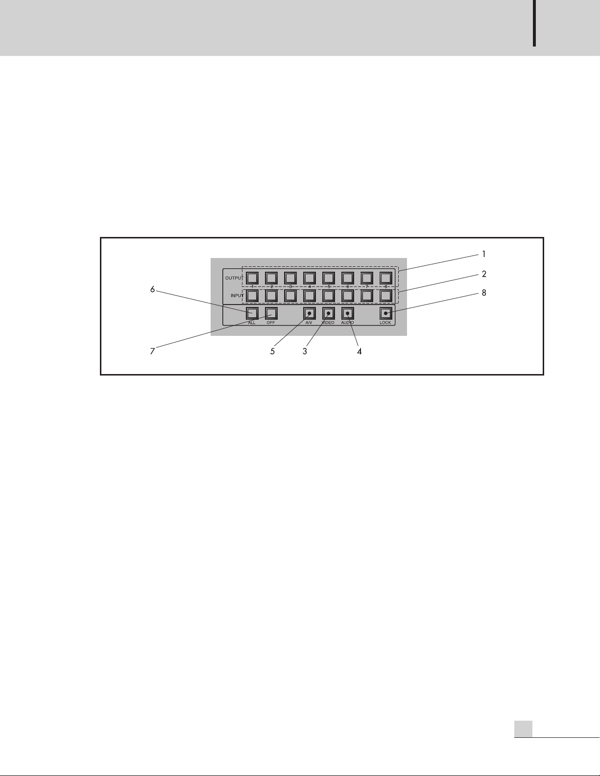
1. DISPLAY WINDOW
Displays the video input channel status which is output to each video/audio output terminal.
“1”~”8” shows each channel, and if “0” is displayed, nothing will be output.
2. INPUT/OUTPUT SELECT BUTTON
- Output : select the channel you want to output. Push this button, and then display window of corresponding
channel will blink. If the input channel to be output is selected while blinking, display window will
change to the corresponding input channel and blinking will stop.
After start blinking, selection will be cancelled if there is no input for about 10 seconds.
- Input : select the input channel to be output to each output terminal.
3. ALL/OFF BUTTON
- ALL : select all output channels. If push this button, display windows of all channels will blink. After start
blinking, selection will be cancelled if there is no input for about 10 seconds. ALL buttons are used
when you want to output one channel in all outputs or disconnect all outputs.
- OFF : it is used when disconnect the output channel. After selecting the OUTPUT SELECT button, push OFF
button, and then display window shows “0” and nothing will be output.
4. MODE SELECT BUTTON
Sets up the mode status of No. 2 and 3 SELECT SWITCH.
- A/V : it sets up No. 2 and 3 SELECT button mode status to simultaneous control mode of Video and Audio.
- Video : it sets up No. 2 and 3 SELECT button mode status to Video Control Mode.
- Audio : it sets up No. 2 and 3 SELECT button mode status to Audio Control Mode.
5. LOCK BUTTON
It is the button to prevent the human error. After all channel settings are completed, click this button for 5
times, and then all buttons on the front will not work while LED of buttons will be displayed.
To unlock, push it for 5 times again, and then LED will be OFF. Lock function will not be cleared even after
turning off the power and turning it on again.
4
HDMS-0808
Page 7

6. POWER SWITCH
t is the switch for power ON/OFF.
I
VIDEO AUDIO MATRIX SWITCHER
HDMS-0808
5
Page 8

VIDEO AUDIO MATRIX SWITCHER
Rear Panel
Rear Panel
1. AC INPUT
It is AC code input terminal used if user installs the DC adapter in the device.
2. DC INPUT
It is DC 12V/ 3A power input terminal.
3. SELECT IN/OUT JACK
It is used when user wants to implement the parallel motion or remote motion by connecting up to 2 devices.
PIN NO. Signal Name Function
1 CONTROL IN/OUT 1
2 CONTROL IN/OUT 2
3 CONTROL IN/OUT 3
4 CONTROL IN/OUT 4
5 CONTROL IN/OUT 5 Control signal line
6 CONTROL IN/OUT 6
7 CONTROL IN/OUT 7
8 CONTROL IN/OUT 8
9 NC
10 UART1 TX
11 UART1 RX
12 GND
13 GND
14 GND
15 GND
Serial communication
GND
6
HDMS-0808
Page 9

VIDEO AUDIO MATRIX SWITCHER
. RS-232C JACK
4
It is used when you want to do same functions as button is pushed from the front by connecting this device
to PC.
PIN NO. Signal Name Function
1 NC
2 TX Serial communication
3 RX Serial communication
4 NC
5 GND GND
6 NC
7 NC
8 NC
5. VIDEO/AUDIO OUTPUT
Video : display the input video signal to random output terminal selected from the front.
Audio : display the input audio signal to random output terminal selected from the front.
6. VIDEO/AUDIO INPUT
Video: input up to 1~8, maximum 8 channels of FULL HD video signal.
Audio: input up to 1~8, maximum 8 channels of STEREO audio signal.
HDMS-0808
7
Page 10

VIDEO AUDIO MATRIX SWITCHER
RS-232C Control
RS-232C Control
- PROTOCOL
* RS-232C standard
* START Bit 1
* STOP Bit 1
* DATA Bit 8
* PARITY None
* DATA RATE 9600bps
* CODE ASC II
* TERMINATE
How to use
How to use
1. Connect video device
Video input and output to be connected to this device should be connected to RCA JACK located at the
rear side of matrix switch by using component cable.
※ CAUTION : when connecting to other input/output device with component cable, component standard
order (Y, Pb, Pr) should be matched.
8
2. Connect audio device
Audio input and output to be connected to this device should be connected to RCA JACK located at the
rear side of matrix switch by using RCA TYPE CABLE.
At this time, L and R of RCA JACK located at the rear side of matrix switch should be matched.
HDMS-0808
Page 11
How to connect
How to connect
- Way to turn on the power
1. Connect the DC adaptor in the matrix switcher package box to the DC input terminal at the rear of
matrix switcher.
Connect DC jack to DC 12V/3A input and turn on the power switch on the front side of matrix switcher.
2. If they are connected correctly, green light on the power switch button will be on.
- Way to operate the control switch on the front
VIDEO AUDIO MATRIX SWITCHER
1. Select output
Select output by pushing output button No. 1~8 on the front. For example, if No.1 output is selected,
push output No. 1 on the front. At this time, No.1 display window at the left side of the front will blink
for 10 seconds to standby for the input. With same method, user can select anything among No. 1~8 in
the output side. This button is connected to the output terminal on the back.
2. Select input
Select input by pushing input button No. 1~8 on the front. For example, if No.1 input is selected to the
output side, push No.1 output first, and then select the input No.1 when display window No.1 on the left
blinks.
Blinking of No.1 on display window stops and then INPUT No.1 is selected.
With same method, user can select anything among No. 1~8 in the input side. This button is connected
to the input terminal on the back.
3. Select video
As same methods in above 1, Select output and 2. Select input, user can control video signal separately
by pushing the video button on the front. When video button on the front is pushed, green light on the
video button will be on.
4. Select audio
As same methods in above 1, Select output and 2. Select input, user can control audio signal separately
by pushing the audio button on the front. When audio button on the front is pushed, green light on the
audio button will be on.
HDMS-0808
9
Page 12

VIDEO AUDIO MATRIX SWITCHER
5. Select video/audio
oth video and audio signals can be controlled by pushing A/V button on the front. When A/v button
B
on the front is pushed, green light on the A/V button will be on.
6. When controlling all output side no. 1~8
Each output of no. 1~8 can be controlled simultaneously by pushing ALL button on the front. For
example, when output side no. 1~8 displays to the input no. 1, first, push ALL button. Display windows
no. 1~8 on the left side of the front will blink for about 10 seconds. At this time, select input side no. 1.
And then Display window will stop blinking and display window no. 1~8 will all change to no. 1.
7. When turning off each output side
This device can select each output to turn it off and turn off all outputs. For example, when turning off
output side no.1, push output no.1 button, and when display window on front-left will blink, push OFF
button on the front, and then output no.1 will be off. Also, push ALL buttons on the front, and when
display window on front-left will blink, push OFF button to turn off all outputs.
8. How to LOCK
To prevent the human error, this device has the function which locks all buttons on the front. If LOCK
button on the front is pushed for 5 times, green light on the LOCK button will be on and then functions of
this device will be LOCK. If user wants to unlock the LOCK setup, push LOCK button for 5 times, and
then green light will be OFF and function will be unlocked.
- Way to use the control terminal on the rear side.
1. How to operate in parallel by connecting two devices. (MASTER/SLAVE)
This device can do same operation in other device connected with IN/OUT SELECT JACK when
controlling front buttons by connecting with external connection JACK.
First, create the cable which can connect IN/OUT select terminals at rear side of the device by suing 15P
D-SUB JACK among accessories in the box. (Refer to picture) After connecting two devices by using the
cable, check whether SLAVE is operated as same as MASTER when pushing the control button on the
front of MASTER.
MASTER SLAVE
10
HDMS-0808
Page 13

VIDEO AUDIO MATRIX SWITCHER
2. How to connect with PC
his device can be controlled on the PC by using the control program. (RS-232 type)
T
First, by using 9P D-SUB JACK in the box, makes the cable (Male-Female). With the cable, execute the
control program on the PC. Check whether device does same operations with the operation explanation
of icon in the device when clicking the icon on the PC with mouse.
※Control program is not provided with the product. You can download on www.inter-m.com
※Please manufacture it using the shield cable less than 1m.
HDMS-0808
11
Page 14
VIDEO AUDIO MATRIX SWITCHER
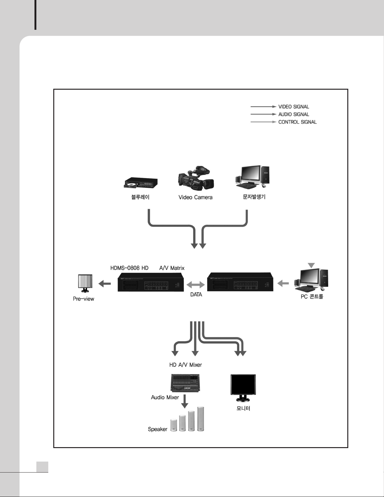
Applications
Applications
12
HDMS-0808
Page 15

Block Diagram
Block Diagram
VIDEO AUDIO MATRIX SWITCHER
HDMS-0808
13
Page 16

VIDEO AUDIO MATRIX SWITCHER
Specifications
Specifications
Electrical Feature
Video
Video Input Y(1.0Vp-p),Pb(0.7Vp-p),Pr(0.7Vp-p) x 8, 75Ω RCA
Video Output Y(1.0Vp-p),Pb(0.7Vp-p),Pr(0.7Vp-p) x 8, 75Ω RCA
Frequency response ±0.5dB
Signal to Noise Ratio 50dB
Crosstalk -46dB
Audio
Audio Input R/L x 8, High Impedence, -10dBv RCA
Audio Output R/L x 8, High Impedence, -10dBv RCA
Frequency response (70Hz~15kHz) ±3dB
Signal to Noise Ratio 60dB
Crosstalk -40dB
Control MICOM Control, RS-232C
General Feature
Operating Temperature -10°C ~ +40°C
Power Source DC12V, AC120V, 220–240V, 50/60Hz
Power Consumption 18W
HDMS-0808
Weight 3.85 Kg / 8.49lb
Dimensions 482(W) x 88(H) x 220(D)mm / 19(W) x 3.4(H) x 8.6(D)in
* Specifications and design subject to change without notice.
14
HDMS-0808
Page 17

※ DIMENSIONS
VIDEO AUDIO MATRIX SWITCHER
HDMS-0808
15
Page 18

VIDEO AUDIO MATRIX SWITCHER
※ CAUTION : please contact a technician for the installation explained as below.
How to setup MASTER-SLAVE
How to setup MASTER-SLAVE
Basically, setup of the device is MASTER mode.
If you want to change to SLAVE mode, down the no. 1 DIP switch in the device.
No.1 Switch
How to connect a DC adapter to the device
How to connect a DC adapter to the device
HDMS-0808 is basically DC power device, but for your convenience, DC adaptor can be installed in the
device.
Refer to following pictures for the installation method.
1. Prepare the DC adaptor provided with the device.
(Adaptor purchased separately may not work with the device.
2. Open the case and install the adaptor to bracket.
16
HDMS-0808
Page 19

VIDEO AUDIO MATRIX SWITCHER
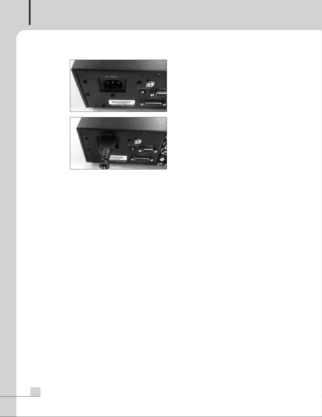
3. Remove the AC INPUT cover on the rear side of the
evice.
d
4. Install the removed AC INPUT cover to adaptor
bracket to fix the adaptor.
5. Connect DC JACK to DC IN in the device.
Arrange the cables with cable tie, etc.
HDMS-0808
17
Page 20
VIDEO AUDIO MATRIX SWITCHER
6. Close the device case, and connect AC code to AC
NPUT terminal on the rear side.
I
Arrange the cables with cable tie, etc.
18
HDMS-0808
Page 21

VIDEO AUDIO MATRIX SWITCHER
Service
Service
Procedures
Take steps to insure the problem is not related to operator error or other products within the system. Once it is
certain that the problem is related to the product, contact your warranty provider as described in the warranty
section of this manual.
Variations and Options
Variations and Options
Variations
Variations of this product exist to reflect the variations in AC power requirements throughout the world. Product
supplied through local sources are compatible with local AC power requirements.
Options
No optional items are available for this product.
Warranty
Warranty
Warranty terms and conditions vary by country and may not be the same for all products. Terms and conditions
of warranty for a given product may be determined first by locating the appropriate country which the product
was purchased in, then by locating the product type.
To obtain specific warranty information and available service locations, contact Inter-M directly or the
authorized Inter-M Distributor for your specific country or region.
HDMS-0808
19
Page 22

NOTE
Page 23

Inter-M, Ltd. (Korea) began operations in 1983.
Since then, Inter-M has grown to become one of the largest manufacturers
of professional audio and commercial sound electronics equipment in the world.
Inter-M has gained worldwide recognition for its own branded products,
as well as private label manufacturing of electronics sold under other names (OEM).
The company is no longer just a Korean company, but rather a global company
that is truly international in scope, with factories and offices in Korea and China,
and sales and marketing operations located in Japan, Europe, and the U.S.A.
With more than 850 employees around the globe,
Inter-M is well-poised for further growth and expansion.
Inter-M Americas, Inc.
13875 Artesia Blvd. Cerritos, CA 90703 USA
TEL : +1-562-921-0313, FAX : +1-562-921-0370
Home Page : http://www.inter-m.net, E-mail : info@inter-m.net
Inter-M Corporation
Seoul OFFICE:653-5 BANGHAK-DONG, DOBONG-KU, SEOUL, KOREA
TEL : +82-2-2289-8140~8, FAX : +82-2-2289-8149
Home Page : http://www.inter-m.com, E-mail : overseas@inter-m.com
MADE IN KOREA
March 2012 130845
 Loading...