

Page 1

Operation Manual
Emergency Combination System
ECS-9216
Page 2

Contents
Contents
Welcome
Warning.........................................................................................................................................1
Unpacking......................................................................................................................................2
Installation
Environment....................................................................................................................................2
Important Safety Instructions.............................................................................................................2
Features............................................................................................................................................3
Operation ........................................................................................................................................3
Front Panel ......................................................................................................................................4
Rear Panel .......................................................................................................................................5
Installation.......................................................................................................................................7
Applications ....................................................................................................................................9
Block Diagram ..............................................................................................................................11
Specifications ................................................................................................................................12
Service
Procedures....................................................................................................................................13
Schematic.....................................................................................................................................13
Parts List .......................................................................................................................................13
Variations and Options ...............................................................................................................13
Warranty .......................................................................................................................................13
EMERGENCY COMBINATION SYSTEM
Page 3

EMERGENCY COMBINATION SYSTEM
1
ECS-9216
Welcome
Welcome
A personal welcome to you from the management and employees of Inter-M
All of the co-workers here at Inter-M are dedicated to providing excellent products with inherently good value,
and we are delighted you have purchased one of our products.
We sincerely trust this product will provide years of satisfactory service, but if anything is not to your complete
satisfaction, we will endeavor to make things right.
Welcome to Inter-M, and thank you for becoming part of our worldwide extended family!
RISK OF ELECTRIC SHOCK
DO NOT OPEN
CAUTION
CAUTION: TO REDUCE THE RISK OF ELECTRIC SHOCK.
DO NOT REMOVE COVER (OR BACK).
NO USER-SERVICEABLE PARTS INSIDE.
REFER SERVICING TO QUALIFIED SERVICE PERSONNEL.
WARNING
To prevent fire or shock hazard, do not
expose the unit to rain or moisture.
*Do not install this equipment in a confined space such as a book case or similar unit.
*The apparatus shall not be exposed to dripping or splashing and no objects filled with liquids, such vases, shall be placed on the apparatus.
*Worded: “WARNING FOR YOUR PROTECTION PLEASE READ THE FOLLOWING-WATER AND MOISTURE: Unit should not be used
near water(e.g. near a bathtub, washbowl, kitchen sink, laundry tub, in a wet basement, or near a swimming pool, etc). Care should be taken
so than objects do not fall and liquids are not spilled into the enclosure through openings.”
This symbol is intended to alert the user to the
presence of uninsulated “dangerous voltage” within
the product’s enclosure that may be of sufficient
magnitude to constitute a risk of electric shock to
persons.
This symbol is intended to alert the user to the
presence of important operation and maintenance
(servicing) instructions in the literature accompanying
the appliance.
Caution: To prevent electric shock do not use this (polarized) plug with
an extension cord, receptacle or other outlet unless the blades
can be fully inserted to prevent blade exposure.
Attentions: Pour prévenir les chocs électriques ne pas utiliser cette
fiche polarisée avec un prolongateur, une prise de courant
on une autre sortie de courant, sauf si les lames peuvent
étre insérées à fond sans en laisser aucune partie à
découvert.
Page 4

EMERGENCY COMBINATION SYSTEM
2
ECS-9216
Installation
Installation
Environment
Never place this product in an environment which could alter its performance or reduce its service life. Such
environments usually include high levels of heat, dust, moisture, and vibration.
Important Safety Instructions
1. Read these instructions.
2. Keep these instructions.
3. Heed all warnings.
4. Follow all instructions.
5. Do not use this apparatus near water.
6. Clean only with dry cloth.
7. Do not block any ventilation openings. Install in accordance with the manufacturer’s instructions.
8. Do not install near any heat sources such as radiators, heat registers, stoves, or other apparatus (including
amplifiers) that produce heat.
9. Do not defeat the safety purpose of the polarized or grounding-type plug. A polarized plug has two blades
with one wider than the other. A grounding type plug has two blades and a third grounding prong. The wide
blade or the third prong are provided for your safety. If the provided plug does not fit into your outlet, consult
an electrician for replacement of the obsolete outlet.
10. Protect the power cord from being walked on or pinched particularly at plugs, convenience receptacles, and
the point where they exit from the apparatus.
11. Only use attachments/accessories specified by the manufacturer.
12. Use only with the cart, stand, tripod, bracket, or table specified by the manufacturer, or sold with the apparatus.
When a cart is used, use caution when moving the cart/apparatus combination to avoid injury from tip-over.
13. Unplug this apparatus during lightning storms or when unused for long periods of time.
14. Refer all servicing to qualified service personnel. Servicing is required when the
apparatus has been damaged in any way, such as power-supply cord or plug is
damaged, liquid has been spilled or objects have fallen into the apparatus, the
apparatus has been exposed to rain or moisture, does not operate normally, or has
been dropped.
S3125A
Unpacking
Please take a few minutes to read this manual to familiarize yourself with important information regarding
installation, product features, and operation.
As with most electronic devices, ORIGINAL PACKAGING (OR EQUAL) IS REQUIRED in the unlikely event that
the product needs to be returned for servicing.
S3125A
Page 5

EMERGENCY COMBINATION SYSTEM
3
ECS-9216
Features
Features
- PRIORITY CONTROL
It controls the priority of emergency, timer, remote1, remote2, main(normal).
- AUTO FIRE SENSOR
The fire alarm will be given automatically to the designated areas by detecting fire sensor input.
- SPEAKER SWITCHING ON EMERGENCY OR NORMAL(MAIN)
You can control the speaker relay on emergency or normal(main) mode by using the speaker switch on front
panel.
- DISPLAY STATUS
You can easily check the priority status.
- 2 AND 3 WIRE SPEAKER LINE SYSTEM
You can control the speaker line on the 2 wire system or 3 wire system.
- EXTENSION FUNCTION
You can easily expand by connecting additional ECS-9216.
Operation
Operation
1. Supply the power.
2. The fire alarm will be given automatically if the fire sensor signal is detected.
3. Select the speak channel after selecting on Emergency or Normal. On Normal mode, the speaker channel led
is displayed on green. On Emergency mode, the speaker channel led is displayed on red.
4. The all switch is for selecting all 16 speaker channels.
5. The priority is EMERGENCY > TIMER > REMOTE1 > REMOTE2 > MAIN. The priority status is displayed on
the priority status led.
Make certain that speakers and input sources are properly connected before switching the unit on.
Keep volume levels turned down before switching on.
NOTE: The system’s operation is delayed by approximately three seconds after pressing the power switch. This
is due to the built-in protection circuitry, designed to protect the speakers and other system components.
Page 6

EMERGENCY COMBINATION SYSTEM
4
ECS-9216
Front Panel
Front Panel
1. ALL SWITCH AND LED
This switch selects all 16 speaker outputs simultaneously.
2. EMERGENCY/NORMAL SELECT SWITCH AND MODE DISPLAY LED
This switch selects the mode(Emergency/Normal). On the Emergency mode, the mode display led is red. On
the Normal mode, the mode display led is green.
3. PRIORITY STATUS DISPLAY LEDS
These leds display the priority status. The priority is Emergency > Timer > Remote1 > Remote2 > Main(BGM).
4. SPEAKER CHANNEL SELECT SWITCHS AND SPEAKER CHANNEL LEDS
These switch select individual channel 1 through 16. On the Emergency mode, the speaker channel leds are
red. On the Normal mode, the speaker channel leds are green.
21 3
ALL
ES/PS
ZONE 1 ZONE 2 ZONE 3 ZONE 4 ZONE 5 ZONE 6 ZONE 7 ZONE 8
4
ZONE 9 ZONE 10 ZONE 11 ZONE 12
EMERGENCY TIMER REMOTE 1 REMOTE 2 MAIN
ZONE 13 ZONE 14 ZONE 15 ZONE 16
Page 7

EMERGENCY COMBINATION SYSTEM
5
ECS-9216
Rear Panel
Rear Panel
1. REMOTE MIC STATION 1 CONNECTOR
This connector is for input of Remote Mic station 1(Inter-M RM-916).(Figure 1)
2. REMOTE MIC STATION 2 CONNECTOR
This connector is for input of Remote Mic station 2(Inter-M RM-916).(Figure 1)
3. EMERGENCY PANEL CONNECTOR
This output connector controls the Inter-M EP-9216.(Figure 2)
4. FIRE SENSOR INPUT CONNECTOR
This connector is for input of fire sensors.(Figure 3,4)
5. COMMON TERMINAL
This terminal is for use of fire sensor common.
6. POWER DISTRIBUTOR TERMINAL
This terminal controls the Inter-M Power Distributor(ex: PD-9359). This is connected to the remote control
switch of Power Distributor.
7. TIMER SWITCH TERMINAL
This terminal is for input of the Inter-M Timer(ex: PW-9242N). This is connected to the timer switch of Inter-M
Timer. All speaker channels will be selected when the timer switch is on.
8. LINK IN CONNECTOR
This connector is for extension of additional ECS-9216. This is connected to the link out of an additional ECS-9216.
215
EMG/PANEL
CH 12 CH 11 CH 10 CH 9
CH 16 CH 15 CH 14 CH 13
COMEM HOT COMEM HOT COMEM HOT COMEM HOT
MADE IN KOREA
CH 4
CH 8
COMEM HOT
(1~8) (9~16)
CH 2
CH 3
CH 6
CH 7
COMEM HOT
COMEM HOT
CH 1
CH 5
COMEM HOT
11
6 7 8 9 1034
HCHC CHCHCHHCHCHC
12
DC OUT
DC IN
DC 24V
1234910112 1
5678141516 13
Page 8

EMERGENCY COMBINATION SYSTEM
6
ECS-9216
9. LINK OUT CONNECTOR
This connector is for extension of additional ECS-9216. This is connected to the link in of an additional ECS-9216.
10. DC INPUT/OUTPUT CONNECTOR
This connector is the DC power input and output connector. The DC input is for the connection of 24VDC
power supply. The DC output is for the connection of 24VDC power supply to an additional unit in the system.
11. SPEAKER OUTPUT TERMINAL
This terminal is for the speaker line output.
12. AMP INPUT TERMINAL
This terminal is for connecting to the speaker output of the amplifier.
Page 9

EMERGENCY COMBINATION SYSTEM
7
ECS-9216
Installation
Installation
* CAUTION
A PD-9359 is able to supply DC 120W
so, please set the total DC power of devices (Ref: ECS-9216 is 14W, EP-916 is 4W, RM-916 is 6W) under
maximum power supply by PD-9359.
1. Turn off the power before installation of the system. Installing on the power-on may make a trouble.
2. Connect the DC power input to the emergency DC power supply of Power Distributor(ex: PD-9359).
3. Connect the remote mic station connector 1,2 to the Inter-M RM-916(Figure 1).
4. Connect the emergency panel connector to the Inter-M EP-9216(Figure 2).
5. Connect the fire sensor input connector to the fire panel. Each 16 fire sensor input channels have 3
ports(Figure 3,4).
6. Connect the power distributor terminal to the remote control switch of Inter-M Power Distributor.
7. Connect the timer switch terminal to the remote out of Inter-M Timer(ex: PW-9242N).
8. Connect the link in/out to the additional ECS-9216 to expand system.
9. Connect the amp input terminal to the speaker out of an amplifier.
10. Connect the speaker output terminal to the speaker.
- Remote mic station connector pin NO and function.
(Figure 1)
- Emergency panel connector pin NO and function.
(Figure 2)
Page 10
EMERGENCY COMBINATION SYSTEM
8
ECS-9216
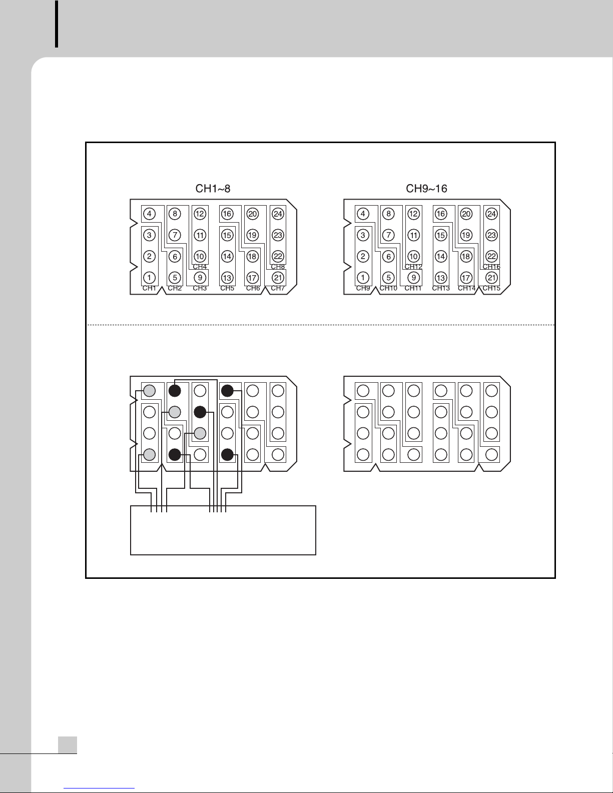
Connect the fire sensor signal of fire panel to the fire sensor input of ECS-9216 like Figure 4. The fire alarm will
be given to the speaker channel 1~4 by fire sensor signal 1, and the speaker channel 2~6 by fire sensor signal
2. In figure 4, the fire sensor input channel 2 is simultaneously connected to the fire sensor signal 1,2. The
different fire sensor signal should be connected to the another pin(in this case pin No4 and 5) on the same fire
sensor input channel. Internally the 3 pins of same fire sensor input channel are separated by diodes.
- Fire sensor input connector pin NO and function.
(Figure 3)
- Connection of the fire sensor input connector
(Figure 4)
4
3
2
1
Fire Sensor
Signal 1
8
7
6
5
CH1~8
12
11
10
CH4
9
Fire Sensor
Signal 2
16
15
141318
CH5CH3CH2CH1
24
192023
22
CH8
21
17
CH6 CH7
48
3
2
1
CH9~16
12
7
11
10
6
CH12
59
16
15
141318
CH13CH11CH10CH9
24
192023
22
CH16
21
17
CH14 CH15
Fire Panel
Page 11

EMERGENCY COMBINATION SYSTEM
9
ECS-9216
Applications
Applications
PC-9335A
PHONES
ON
OFF
MAX
MIC/VOLUME
MIN
MIC
OUTPUT
STAND-BY
POWER
ON
OFF
CLIP
40dB
10dB
PROT
OUTPUT & PROTECTION
FIRE
EP-9216
ZONE 13 ZONE 14 ZONE 15 ZONE 16
EMERGENCY TIMER REMOTE 1 REMOTE 2 MAIN
PA-9336
PW-9242N
ES/PS
ALL
ECS-9216
ZONE 9 ZONE 10 ZONE 11 ZONE 12
Audio Line
Control Line
Fire Panel
ZONE 1 ZONE 2 ZONE 3 ZONE 4 ZONE 5 ZONE 6 ZONE 7 ZONE 8
Page 12

EMERGENCY COMBINATION SYSTEM
10
ECS-9216
PC-9335A
PW-9242N
Fier Panel
SPEAKER
EP-9216
ECS-9216
PA-9336
PD-9359
AC IN
PB-9207A
Audio Line
Control & Power Line
Page 13

EMERGENCY COMBINATION SYSTEM
11
ECS-9216
Block Diagram
Block Diagram
AMP
INPUT(CH1~16)
FIRE SENSOR
INPUT(CH1~16)
NOR, EM
RELAY(CH1~16)
CPU
AMP
OUPUT(CH1~16)
PD OUTPUT,
RS-422 INTERFACE,
TIMER IN INTERFACE
LED INTERFACE
RM1, RM2 INPUT
FRONT SWITCH,
PANEL
INTERFACE
EMERGENCY
Page 14

EMERGENCY COMBINATION SYSTEM
12
ECS-9216
Specifications
Specifications
ECS-9216
Priority Control Emergency > Timer > Remote1 > Remote2 > Main
Link in/out Interface RS-422(19200bps, Data 8bits, Stop 1bit, Non Parity bit, Start 1bit)
Link in/out Interface Distance 1.2km
Operating Temperature 0°C ~ +40°C
Power Source 24VDC
Power Consumption 14W
Weight 5kg/11.0lb
Dimensions 482(W)x88(H)x280(D)mm/19(W)x3.5(H)x11(D)in
* Specifications and design subject to change without notice.
Page 15

EMERGENCY COMBINATION SYSTEM
13
ECS-9216
Service
Service
Procedures
Take steps to insure the problem is not related to operator error or other products within the system. Information
provided in the troubleshooting portion of this manual may help with this process. Once it is certain that the
problem is related to the product contact your warranty provider as described in the warranty section of this
manual.
Schematic
A Schematic is available by contacting your warranty provider.
Parts List
A Parts List is available by contacting your warranty provider.
Variations and Options
Variations and Options
Variations
Products supplied through legitimate sources are compatible with local AC power requirements.
Options
No optional items are available for this product.
Warranty
Warranty
Warranty terms and conditions vary by country and may not be the same for all products. Terms and conditions
of warranty for a given product may be determined first by locating the appropriate country which the product
was purchased in, then by locating the product type.
To obtain specific warranty information and available service locations contact Inter-M directly or the authorized
Inter-M Distributor for your specific country or region.
Page 16

MADE IN KOREA
May 2006 9007109910
Inter-M, Ltd. (Korea) began operations in 1983.
Since then, Inter-M has grown to become one of the largest manufacturers
of professional audio and commercial sound electronics equipment in the world.
Inter-M has gained worldwide recognition for its own branded products,
as well as private label manufacturing of electronics sold under other names (OEM).
The company is no longer just a Korean company, but rather a global company
that is truly international in scope, with factories and offices in Korea and China,
and sales and marketing operations located in Japan, Europe, and the U.S.A.
With more than 850 employees around the globe,
Inter-M is well-poised for further growth and expansion.
INTER-M AMERICAS, INC.
1 EAST BEACON LIGHT LANE CHESTER, PA USA 19013-4409
TEL : 1-610-874-8870, FAX : 1-610-874-8890
Home Page : http://www.inter-m.net, E-mail : service@inter-m.net
INTER-M Corporation
SEOUL OFFICE:653-5 BANGHAK-DONG, DOBONG-KU, SEOUL, KOREA
TEL : 82-2-2289-8140~8, FAX : 82-2-2289-8149
Home Page : http://www.inter-m.com, E-mail : export@inter-m.com
 Loading...