

Page 1
MADE IN KOREA
August 29 2012
Page 2
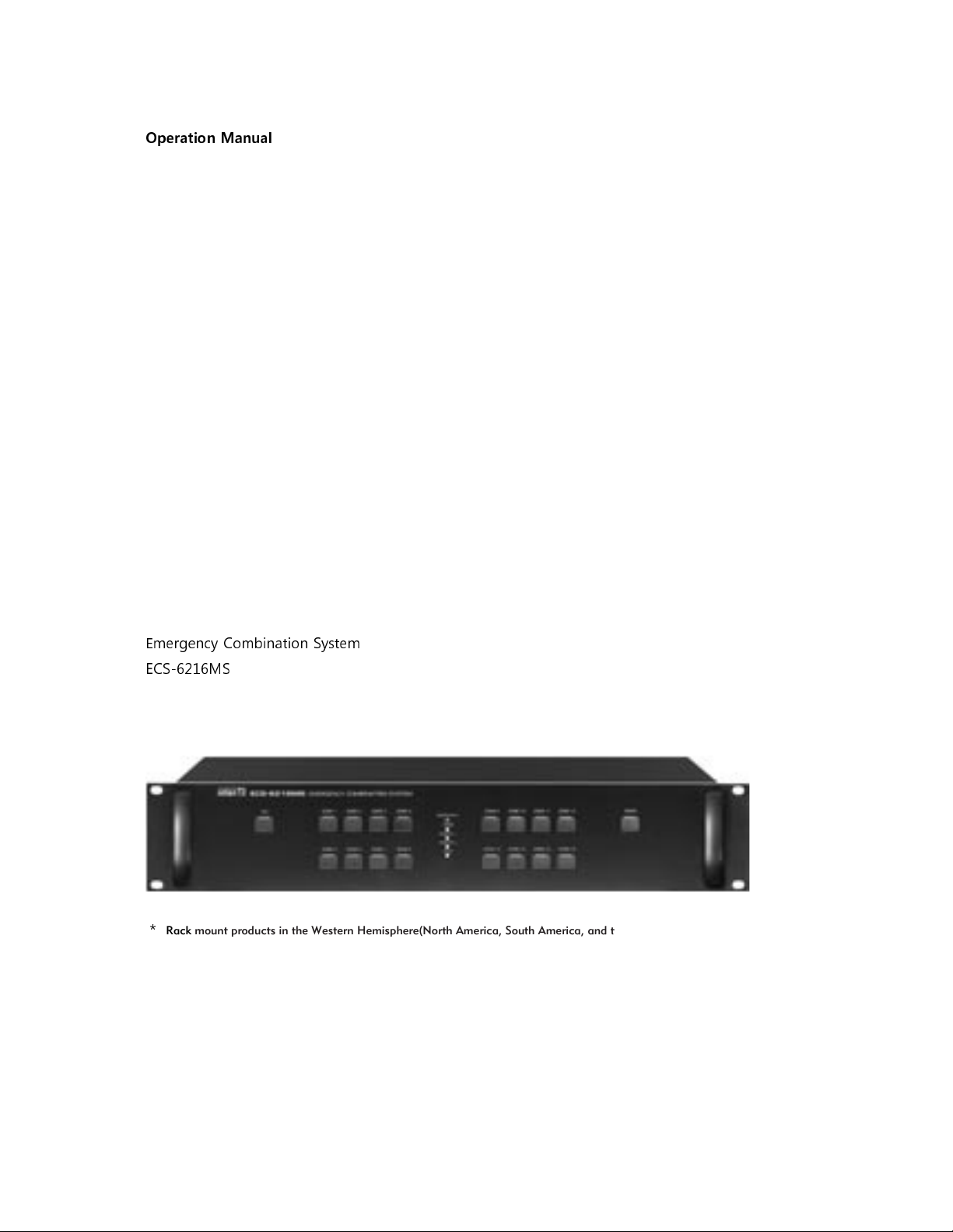
Operation Manual
Emergency Combination System
ECS-6216MS
*
Rack mount products in the Western Hemisphere(North America, South America, and the Caribbean)
do not have handles installed due to customer preference.
Page 3
Page 4
Page 5
Page 6

Features
- COMPREHENSIVE SYSTEM
System consists of RELAY GROUP, SPEAKER SELECTOR and TERMINAL BOARD.
- AUTOMATIC FIRE DETECTING FUNCTION
16 trigger channels can be connected to sensors in order to automatically broadcast fire alarm and
Emergency messaging to corresponding channel via the PX-6216.
- MANUAL BROADCAST CONTROL
Manual broadcasting is possible via the front panel selector switches.
- CONTROL THE 3-WIRE TYPE SPEAKER TRACK
It consists of the channels for the common and emergency broadcastings to make 3-wire type
broadcast possible.
- CHANNEL EXPANSION AND RS-485 COMMUNICATION INTERFACE
The system can be expanded to up to 160 zones by connecting additional ECS-6216S.
- INSTALLATION TIME AND SPACE
The systems ease of installation reduces installation time and space.
Page 7

Equipment Setup and Inspection
1. Setup
.
1) Set the equipment number in accordance with wiring conditions by using rear panel DIP switch.
2) Setup method is shown in below table, and number on the ON switch will be the equipment number.
*
Caution: If an equipment number is not set, all zone indicator LEDs will blink.
If the number is already used, communication will not be available.
In the above case, please check the equipment number set-up.
3) Zone allocations of set equipment are as follow.
2. TERMINATION Switch (LOAD/OPEN) Setting
1) For systems linked by RS-485 communication interface, it is necessary to set the termination
switch(LOAD/OPEN) on the rear panel to stabilize data transfer.
2) Set the termination switch to LOAD only for the first and last-numbered equipment units.
All others must be set to OPEN.
*
Caution: Communication error may occur if setting is performed incorrectly..
Page 8

1. SPEAKER ZONE SELECT BUTTON AND DISPLAY (1~16)
LED will be turned on for the selected zone by the corresponding button which selects the individual
broadcast zone.
LED will be red in case of emergency broadcasting (ES) and will be green in case of general
broadcasting (PS).
The zone broadcasting can be selected only if more than 1 zone in the same bus is being broadcasted.
(Refer to system operation manual)
Page 9

1. FIRE SENSOR or TRIGGER CONTACT INPUT TERMINAL
It is the terminal connected to the sensor output of the fire receiving panel or external trigger contact
and sends the emergency, evacuation broadcasting or Emergency Messaging to the zone.
1) Using the MACRO function, selection and grouping of multiple broadcast zones can be
assigned for each input channel.
However, this function can be only be configured using the Windows program. The setting
information is downloaded from PC to PX-6216 and saves in an internal memory.
(Refer to System Operation Manual)
2) A maximum 160 zones can be selected and saved in one input channel.
3) For example, if you select and memory the zone 1, 2 and 3 to channel NO.1, emergency
broadcasting will be transmitted to zone 1, 2 and 3 at the same time when a fire sensor is
received on channel NO.1.
2. PD, COM TERMINAL
1) PD Contact Point Output Terminal
This is the contact output terminal used for controlling the operations of the power distributor.
Contact point will be transmitted when one speaker zone is ON or on fire sensor input.
It is connected to REMOTE SW terminal of the power distributor.
2) Com Terminal
It is connected to COM terminal of fire receiving panel.
3. LINK IN/OUT TERMINAL
LINK IN terminal is connected to previous equipment and LINK OUT terminal is connected to next
equipment.
Page 10

*
Same for all IN/OUT terminals.
4. TERMINATION SWITCH (LOAD/OPEN)
This switch is set for stable data receive/transmit of LINK IN/OUT.
Please refer to Equipment Setting and Inspection (Page 3) for detail information.
*
Caution: Communication error may occur if setting is performed incorrectly..
5. UPGRADE TERMINAL (ISP)
It is the terminal to upgrade the software of the equipment and is not used generally.
6. VOICE FILE CONTROL TERMINAL
Communication terminal to be used for controlling Inter-M’s VOICE FILE equipment on Windows
program.
1) RS-232 communication terminal for controlling source equipement.
2) Maximum recommended communication distance is about 12M.
3) PIN OUT Specification
7. SPEAKER OUT TERMINAL
3-wire type Speaker terminal connects each speaker channel.
1) In PS mode, transmit through HOT terminal pnly.
2) In ES mode, transmit through both HOT/EM terminal.
8. AMP IN TERMINAL
Connected to output of AMP.
9. ADDRESS SETTING SWITCH
Sets the address for each equipment when the system is expanded and linked.
Please refer to Equipment Setting and Inspection (Page 3) for detail information.
10. POWER INPUT TERMINAL
DC Power input terminal. Caution please observe polarity when connecting DC 24V.
Connect to an external power supply or inter-M power distributor. Connect to un-switched power
supply.
Page 11

Page 12

Page 13

Page 14

 Loading...