

Page 1

Operation Manual
Digital Video Recorder
DSR-815/1608
Page 2

DIGITAL VIDEO RECORDER
Welcome
Welcome
A personal welcome to you from the management and employees of Inter-M
All of the co-workers here at Inter-M are dedicated to providing excellent products with inherently good
value, and we are delighted you have purchased one of our products.
We sincerely trust this product will provide years of satisfactory service, but if anything is not to your
complete satisfaction, we will endeavor to make things right.
Welcome to Inter-M, and thank you for becoming part of our worldwide extended family!
* It can be heated up if you use this product in closed box or ill-ventilated place.
RISK OF ELECTRIC SHOCK
DO NOT OPEN
CAUTION
CAUTION: TO REDUCE THE RISK OF ELECTRIC SHOCK.
DO NOT REMOVE COVER (OR BACK).
NO USER-SERVICEABLE PARTS INSIDE.
REFER SERVICING TO QUALIFIED SERVICE PERSONNEL.
WARNING
To prevent fire or shock hazard, do not
expose the unit to rain or moisture.
*Do not install this equipment in a confined space such as a book case or similar unit.
*The apparatus shall not be exposed to dripping or splashing and no objects filled with liquids, such vases, shall be placed on the apparatus.
*Worded: “WARNING FOR YOUR PROTECTION PLEASE READ THE FOLLOWING-WATER AND MOISTURE: Unit should not be used near
water(e.g. near a bathtub, washbowl, kitchen sink, laundry tub, in a wet basement, or near a swimming pool, etc). Care should be taken so than
objects do not fall and liquids are not spilled into the enclosure through openings.”
Service Instructions
*Worded: “Caution: These servicing instructions are for use by qualified service personnel only. To reduce the risk of electric shock, do not perform
any servicing other than that contained in the operating instructions unless you are qualified to do so.”
*Location: Instruction Manual.
NOTE : This equipment has been tested and found to comply with the limits for a Class A digital device, pursuant to Part 15 of the FCC Rules.
These limits are designed to provide reasonable protection against harmful interference when the equipment is operated in a commercial
environment. This equipment generates, uses, and can radiate radio frequency energy and, if not installed and used in accordance with
the instruction manual, may cause harmful interference to radio communications. Operation of this equipment in a residential area is likely
to cause harmful interference in which case the user will be required to correct the interference at his own expense.
This symbol is intended to alert the user to the
presence of uninsulated “dangerous voltage” within
the product’s enclosure that may be of sufficient
magnitude to constitute a risk of electric shock to
persons.
This symbol is intended to alert the user to the
presence of important operation and maintenance
(servicing) instructions in the literature accompanying
the appliance.
Caution: To prevent electric shock do not use this (polarized) plug
with an extension cord, receptacle or other outlet unless
the blades can be fully inserted to prevent blade exposure.
Attentions: Pour prévenir les chocs électriques ne pas utiliser cette
fiche polarisée avec un prolongateur, une prise de courant
on une autre sortie de courant, sauf si les lames peuvent
étre insérées à fond sans en laisser aucune partie à
découvert.
2
DSR-815/1608
2
Page 3

DIGITAL VIDEO RECORDER
3
DSR-815/1608
Contents
Contents
Welcome ..........................................................................................................................................2
Precautions (Warning) in manipulation of the set ..................................................................................5
Before getting started..........................................................................................................................6
Safety Notice .....................................................................................................................................6
System Components.......................................................................................................................8
System Introduction
1. System Features .............................................................................................................................9
2. Major Functions .............................................................................................................................9
3. Precautions Before Getting Started...................................................................................................9
Front Panel ....................................................................................................................................10
Rear Panel .....................................................................................................................................12
Remote Control .............................................................................................................................14
DVR Monitoring Program
1. Monitoring Screen(Initial Screen)...................................................................................................15
1-1. Monitoring(Live) View ...........................................................................................................16
1-2. Submenu..............................................................................................................................16
1-3. Pan/Tilt Camera Control .......................................................................................................17
2. System Setup ...............................................................................................................................20
2-1. Camera Setup ......................................................................................................................22
2-2. Record Setup ........................................................................................................................24
2-3. Event & Motion Setup............................................................................................................26
2-4. Storage & Backup.................................................................................................................28
2-5. Network Setup......................................................................................................................30
2-5-1. IP Setup......................................................................................................................30
2-5-2. DDNS........................................................................................................................30
2-5-3. Service Port ................................................................................................................31
2-5-4. Event Server ...............................................................................................................31
2-6. System Setup ........................................................................................................................32
2-6-1. System Information......................................................................................................32
2-6-2. Password Setup ..........................................................................................................33
2-6-3. Date & Time Setup ......................................................................................................34
2-6-4. Pan/Tilt Setup.............................................................................................................35
2-6-5. System Upgrade .........................................................................................................36
3. Search Function ...........................................................................................................................37
Page 4

DIGITAL VIDEO RECORDER
4
DSR-815/1608
UCM
1. Default Screen and Using the Functions ........................................................................................40
1. Monitoring Screen....................................................................................................................40
2. Camera Selection.....................................................................................................................41
3. Screen Split/Screen Conversion ................................................................................................41
4. Two-way Audio (DSR-815/1608 does not Supports it) ...............................................................42
5. Audio Volume Control..............................................................................................................42
6. Index Information Windows......................................................................................................42
7. Function Buttons.......................................................................................................................42
7-1. Environment Setup ............................................................................................................43
7-2. Server List Management ....................................................................................................44
8. Function Tab Buttons ................................................................................................................46
9. Connection/Disconnection........................................................................................................49
10. Quit......................................................................................................................................50
2. Search Function...........................................................................................................................51
1. Search Window.......................................................................................................................51
2. Search Screen Split ..................................................................................................................52
3. Index Information Window .......................................................................................................52
4. Function Tab Buttons ................................................................................................................52
5. Play Control.............................................................................................................................54
6. Time Table...............................................................................................................................55
7. Function I ................................................................................................................................56
- Search Setup .........................................................................................................................56
- Book Mark ............................................................................................................................57
8. Function II................................................................................................................................58
- AVI Conversion......................................................................................................................58
- Snap Shop ............................................................................................................................59
- Panorama .............................................................................................................................60
- Event(Smart) Search ...............................................................................................................61
- Quit......................................................................................................................................61
3. Image Analysis ...........................................................................................................................62
Automatic Remote Control
1. Automatic Remote Connect AgentView ..........................................................................................65
2. Remote Connect Screen Interlocked with UCM................................................................................66
Copy(Downloadng) Data in Remote .........................................................................................67
Specifications ................................................................................................................................70
Supplement
A. Understanding of Dynamic IP .......................................................................................................71
B. Register flow IP server user............................................................................................................72
C. Install an additional hard disk (HDD).............................................................................................76
D. Recording Time Table...................................................................................................................79
E. Recording size and recording size calculation method ....................................................................80
Page 5

DIGITAL VIDEO RECORDER
5
DSR-815/1608
Precautions(Warning) in manipulation of the set
Precautions(Warning) in manipulation of the set
CAUTION
■ Please reset date and time in the set when setting up it for a first time.
■ Security system was built in the set, and especially the HDD in it is very sensitive to shock or
static electricity.
■ Normal operating temperatures are from 0 to 40 degrees centigrade.
■ Keep away from a high temperature and a high relative humidity when stocking the set.
■ Save data before unplugging or turning off the power supply.
■ Our company shall not responsible for data stored in the hard disk.
■ Our guaranty shall not cover a fault being caused by a customer.
■ Always back up important data.
■ Only HDD of the ATA type is adoptable to be added up when changing HDDs (In maximum,
3 units are possible to be installed additionally).
■ Be cautious that sticker or label attached on the set may become off or damaged will cause a
direct fault.
■ Distributor or user should pay attention that this system has been registered for an electromagnetic compliance of business purpose. If wrongly sold or purchased, please exchange it for
home use only.
Page 6

DIGITAL VIDEO RECORDER
Safety Notice
Safety Notice
1. Precautions before installing the system
- Disassemble the packing and then place the system on a dried and plain floor.
- Install the system a place where it ventilates well.
- Keep away electromagnetic waves or a strong magnetism (for example, speaker, etc.) from your
installing place.
- A place where it sun shines directly or it is near to heating device is not suitable for your installing place
in order to protect the system against direct sunlight or strong heat.
- A place where it is exposed to outdoor or it is cold is not suitable for your installing place.
- Be careful that you will not be injured from an installing tool or equipment on the installing place.
- A place where it has strong vibrations or a high relative humidity is not suitable to install the system.
- Check up the voltage before connecting to power cord.
- Dispose the vinyl pack after disassembling the packing. (Keep away from children, if a child puts on it
on the head, it will be vary dangerous.)
2. Cautions in use of the system
- If you disassemble the system to repair, in some cases, you may not be available to get a repair and
maintenance. Therefore, you should contact your distributor when the system will get out of order.
- Before using the system, please read this manual thoroughly.
- If you disassemble the system, you may not be available to get an after sales service. You should contact the customer support center when the system will get fault.
- Do not touch an electric outlet or power cord with your wet hand.
- Pat attention that power cord shall be plugged in electric outlet correctly.
- Do not wipe the system with a alcoholic substance such as thinner or benzene.
- Do not touch any terminals being exposed to the exterior.
- Operate the system in a place where it ventilates sufficiently.
- Do not disassemble or repair the system arbitrarily.
- Do not put a heavy object on the system upper part.
- Do not move the system while operating it.
- A repetition of power on and off without system off during an operation may damage the HDD.
- When the system gives out fumes or odor immediately switch off the power supply and then contact
your distributor to get a technical support and repair and maintenance.
2
DSR-815/1608
6
Before getting started:
Before getting started:
The Operating Instructions incorporate the methods for operating or configuring the DVR system.(hereinafter
referred to as “the system”) And the programs. Before using the system, please read this manual thoroughly.
After disassembling the packing, please confirm the parts and contact to your distributor if you may have a
question. Cautions on safety (You must check up the following articles.)
Page 7

DIGITAL VIDEO RECORDER
3
DSR-815/1608
7
Manufacturers Guarantee
This system is guaranteed against failure within 1 year of the purchase date.
We reserve the right to replace components prior to the replacement of the complete system.
Do not attempt to repair any internal components as this may void warranty.
This guarantee does not cover instances of system abuse, physical damage or other issues beyond the
manufacturers control.
In the event of any failure, contact your supplier.
Free maintenance or replacement service is not applicable if:
1. The system was damaged due to user error or abuse.
2. The user did not follow the instructions in the user guide.
3. The rated voltage and frequency specified in the user guide were not observed.
4. Replacing of consumables or cleaning of the system is required.
5. System failure following repair by unauthorized personnel.
※The consuming width shift and equipment cleaning are excepted from maintenance conservativeness.
After the free maintenance period has expired, you can have your system upgraded or repaired by your
supplier. Should you require these services, please ask your supplier for more information.
- Please note other terms and conditions may vary with different suppliers.
- You should quote the information above when requesting maintenance or service.
Product Name
Product Number
Supplier / Telephone
Date of Purchase
Guarantee Period
Customer
Name
Information
Address
Telephone
Page 8

DIGITAL VIDEO RECORDER
System Components
System Components
Take out the components in a flat and dry area, and then check the following components are all included.
Components of System
8
DSR-815/1608
RACK BRACKET
DSR MAIN UNIT PROGRAM CD
BATTERY AAA(2)
MOUSE
REMOTE CONTROLPOWER CABLE
USER GUIDE
VOLT & NUT
Page 9

DIGITAL VIDEO RECORDER
9
DSR-815/1608
System Introduction
System Introduction
What is a stand-alone DVR?
It signifies an all-in-one DVR in which an independent system was realized and DVR function was built in.
SYSTEMATIC FEATURES
1. Stability
- Stand alone type DVR system based on the embedded system electronic OS.
- Data are stored in OS and software flash memory, and Watchdog mounted.
2. Convenience
- Support a mouse, applied with GUI in which user’s convenience was focused.
- USB port and A/V output were disposed on the front to give convenience to user.
- Support various interfaces including mouse/jog/shuttle/remote control/front key.
3. Expansion Capabilities
- Basic 250GB HDD supplied.( additionally expanded to 3 HDDs in maximum.)
- Remote monitoring software of Inter-M DVRs (UCM).
- Support Explorer Viewer.
4. Technology
- Realized GUI (Graphical User Interface) based on the Embedded System OS.
5. Performances
- Diversified display outputs (VGA, Composite, video/audio on the front, and support 16 channel LOOP
OUT, DSR-1608: 16 channels, DSR-815: 8 channels)
- Support 4 channel audio input and 1 channel audio output
- Support data backup and software upgrade.
- Monitor through the network./SW upgrade and flow IP.
- Timelaps/Interlock with an event/Record a post event
- Set up a recording per camera, day of the week, or time
- Outer sensor mounted to survey a movement.
MAJOR FUNCTIONS
- It can monitor real time video images from 16 cameras.(DSR-1608: 16 channels, DSR-815: 8 channels)
- It offers various user control interfaces, including mouse, jog shuttle, and key pad + remote control.
PRECAUTIONS BEFORE GETTING STARTED
- Upon factory delivery, administrator’s password was not used but the password was input with “1234”.
- When setting it up for a first time, please confirm date and time, if not confirm to actual time, please reset.
Page 10

DIGITAL VIDEO RECORDER
10
DSR-815/1608
Front Panel
Front Panel
1. POWER LED: It signifies power On or Off state.
NETWORK LED: It signifies network status.
EVENT LED: It signifies an event generation state.
REC LED: It signifies when hard disk runs recording.
2. JOG KEY: It makes playback by unit of frame and is utilized to move an item on the menu.
SHUTTLE KEY: It makes playback by speed multiplication of frame (at a high speed) and is utilized to
change values on an item of the menu.
3. CHANNEL KEY
It selects a numeral button and channel. (Select a channel number and click on “ENTER” and then the
channel will be selected.)
4. RECORD KEY: It makes starting or terminating to playback the whole channels forcibly regardless of any
schedule recording. (Force recording takes priority over scheduled recording.)
MODE KEY: It changes divided screen states (1/4/9/16).
SEARCH KEY: It converses into the searching screen. (It will be selected when playback a recorded
image.)
ALARM KEY: It sets up On/Off mode of alarm by manual.
MENU KEY: It converses into the menu screen. (It will be selected to modify a system configuration.)
PTZ KEY: It changes PTZ Control Mode.
5. ◀, ▲, ▶, ▼, II, I◀◀, ▶▶I
In the menu mode, it moves Cursor and changes a value. In the live screen, it selects an audio channel.
(Up:1Ch, Right: 2Ch, Down :3Ch, Left 4Ch, Pause: Delete a sound.)
In the Pan/Tilt mode, it controls a Pan/Tilt. /In search playback, it is utilized to control a playback.
12 3 4 56
978
Page 11

DIGITAL VIDEO RECORDER
11
DSR-815/1608
6. ENTER KEY: It is utilized as the select button when set up a menu.
RETURN KEY: It is utilized as the button to return to a previous menu or terminate it when set up a menu.
7. AUDIO OUTPUT TERMINAL
Audio output terminal(RCA).
8. VIDEO OUTPUT TERMINAL
Video output terminal (RCA).
9. USB TERMINAL
It is utilized to back up using USB terminal. (USB 2.0 support)
Page 12

DIGITAL VIDEO RECORDER
12
DSR-815/1608
Rear Panel
Rear Panel
1. AC INPUT
This is the terminal to connect AC power outlet.
2. VIDEO INPUT
This is the terminal to input a camera. (16 channels/8 channels)
3. LOOP OUT
This is the Camera Output terminal. (16 channels/8 channels)
4. RS-485
This is the terminal to control a PAN/TILT camera.
5. ALARM OUTPUT
This is the Alarm Output terminal. (4 channels)
6. SENSOR OUTPUT
This is the Alarm Sensor Output terminal. (16 channels/8 channels)
7. LAN
LAN terminal to connect the network.
1 23
1 23
4 5 6 7 8 9 10 11 12 13
4 5 6 7 8 9 10 11 12 13
[DSR-815]
[DSR-1608]
Page 13

DIGITAL VIDEO RECORDER
13
DSR-815/1608
8. USB
USB terminal.
9. AUDIO INPUT
Audio signal input terminal (RCA). (4 channels)
10. AUDIO OUTPUT
Audio signal output terminal (RCA). (1 channel)
11. VGA
VGA video output terminal.
12. MONITOR OUTPUT
This is the terminal to output a composite video signal.
13. CAMERA TYPE
This is the terminal to set up a camera type. (NTSC/PAL)
Page 14

DIGITAL VIDEO RECORDER
14
DSR-815/1608
Remote Control View and Description
Remote Control View and Description
1. ESC (RETURN)
It is utilized as the button to return to a previous
menu or terminate it when set up a menu.
2. ENTER
It is utilized as the select button when set up a menu.
3. 0 ~ 9
It selects a numeral button and channel.(Select a
channel number and click on “ENTER” and then
the channel will be selected.)
4. I◀◀, ▶▶I, ◀, ▶, ▲, ▼, II
In the menu mode, it moves Cursor and changes a
value. In the live screen, it selects an audio channel.
(Up:1Ch, Right: 2Ch, Down :3Ch, Left 4Ch,
Pause: Delete a sound.)
In the Pan/Tilt mode, it controls a Pan/Tilt. In
search playback, it is utilized to control a playback.
5. RECORD
It makes starting or terminating to playback the
whole channels forcibly regardless of any schedule
recording.(Force recording takes priority over
scheduled recording.)
6. MODE
It changes divided screen states.(1/4/9/16)
7. ALARM
It sets up On/Off mode of alarm by manual.
8.
It changes the 4 Channel screen states.
9.
It changes the 9 Channel screen states.
10.
It changes the 16 Channel screen states.
11. SEARCH
It converses into the searching screen.(It will be selected when playback a recorded image.)
12. PTZ
It changes PTZ Control Mode.
13. MENU
It converses into the menu screen.(It will be selected to modify a system configuration.)
123
456
78
RECORD MODE SEARCH
ECS
ENTER
ALARM MENU PTZ
9
0
1
2
3
4
6
5
7
8
9
10
11
12
13
Page 15

DIGITAL VIDEO RECORDER
15
DSR-815/1608
DVR Monitoring Program
DVR Monitoring Program
1. Monitoring Screen (Initial Screen)
The following LOGO screen will appear when the power is switched on the system.
- The system initialization will go on after the LOGO screen appears.
- The following monitoring image screen will appear when the system initialization has been finished normally.
(It takes approximately 60 seconds to display the system monitoring image screen after power ON.)
※ When a new HDD is installed, upon an initial booting it takes more time to initialize HDD newly added.
(HDD newly added is available after having formatted it only.) (Refer to page 27.)
When exchange HDD installed in an existing equipment for a new HDD, it will take more time to initialize
the new HDD and the system and then to appear a live image. (Based on 25oG, it takes approximately
10 minutes.)
※ Please contact your distributor when a live video will not be output continually.
Page 16

DIGITAL VIDEO RECORDER
16
DSR-815/1608
1-1. Monitoring (Live) View : Shows the Camera image and camera connection information.
[ Camera Infomation ]
1) Camera Name : Displays the Configured Camera name.
2) Alarm status : Displays the Alarm status.
3) Record status : Displays the Record status.
(E: Emergence Mode, C: Continuous Mode, S: Sensor Mode, M: Motion Mode, A: Emergence+
[Continuous Or Sensor Or Motion])
4) Index Information Window : Display the Hard disk information, current Date/current Time
※ Change a save capacity, date, or time indication: Click on the wheel button of the mouse or select
RETURN (ESC) Button of the front (remote control).
1-2. Submenu : The following menu will appear when mouse displace in the direction of the bottom of
the screen (date and time indication).
Camera Name
Alarm Status
Record Status
Page 17

DIGITAL VIDEO RECORDER
17
DSR-815/1608
- : Splits the screen into 1 section.
- : Splits the screen into 4 sections.
- : Splits the screen into 9 sections.
- : Splits the screen into 16 sections.
- : Manually Reverses the screen.
- : Manually Forwards the screen.
- : Automatically switches the screen.(default value : 3 seconds)
- : Searches recorded image or Audio.
- : Control a Pan/Tilt Camera.
- : Configures the system.
1-3. Pan/Tilt Camera Control : It controls a pan/tilt camera.
(It will be normally operated when Pan/Tilt setting has been finished in “P/T/Z” setting of the system
sub menus of the setting.)
- Select on the sub menu.
[ Front Key or Remote Control ] : Select “PTZ” key.
- Click on the channel you desire to control.
[ Front Key or Remote Control ] : Select ENTER key after you displace the key you desire using the
lateral direction key ◀▶.
- PTZ has the following GUI.
Page 18

DIGITAL VIDEO RECORDER
18
DSR-815/1608
1) P/T/Z utilizing the mouse
Utilizing the Pan/Tilt sub menu, it is the method that the menu appears when mouse go in this area but it
disappears when the mouse go out of the area.(It is the same method both in a live screen and Playback
menus.)
(1) Pan Left/Pan Right/Tilt Up/Tilt Down : After the whole screen has been divided by 9 parts of shape,
Pan/Tilt will be done making each of rectangles to be conformed with the direction clicked on.
(2) Zoom/Focus : On the menu bar, select “Zoom” or “Focus” key and then it will be controlled by
utilizing the wheel of mouse.
Zoom : (WHEEL UP) : zoom in (see nearly), WHEEL DOWN : zoom out (see far away)
Focus : (WHEEL UP) : focus Near, WHEEL DOWN : focus Far
(3) Speed
It assigns a speed of Pan/Tilt/Zoom/Focus, having a value 1~10. Change a value utilizing the mouse
after clicking on a speed numeral of the edit box using the mouse.
(4) Preset
Preset number : Select a preset number.(Change a value utilizing the wheel of the mouse.)
“Set” : Saves a current camera position and a preset number selected.
“Clear” : Deletes a preset number currently selected.
“Go” : Moves a camera on the preset number selected.
2) P/T/Z utilizing the front key and the remote control.
(1) State information indicator that controls it utilizing the front key.
In PTZ mode, it does not appear. But it appears when you press PTZ button of the front key and it
disappears when you press it again. And it truns as follows if the state indicator appears. It is the state
information indicator that shows up a current state when utilizing the front key.
(It is not an area where to be input from the mouse.)
In he front key, “when you click on the
II
(Pause) button each, it changes mode according to the order
[Zoom] → [Focus] → [Speed] → [Preset:001] → [Zoom] → ... as shown in the following figure.
↓
↓
↓
Page 19

DIGITAL VIDEO RECORDER
19
DSR-815/1608
In each state, it runs as follows when you click on the button.
(2) Use the preset by utilizing the front key
In the preset state as you click on the numeral key of the front key each, the next numeral will appear
according to the numeral key you press. Range of the preset numerals are from 1 to 128. When a
numeral exceeding the range is input, it will be neglected. For example, you input 3, 4, 5 in sequence,
it will input until 34 but not accept 5. In order to input again, while pressing until 34, after pressing
one of I◀◀, and ▶▶I and, ENTER and PTZ Key, you should press again a numeral key then. Of course,
when you press I◀◀ key, the current camera position will be saved in number 34 of the preset, and
when you press ▶▶I key, the reset position number 34 will be deleted, and when you press ENTER key,
the camera will displace the position of number 34 then. PTZ key will disappear the state indicator for
manipulating the front key. Other than, if you run Pan/Tilt or the mouse, it will make disappear it.
Therefore if you press I◀◀ and ▶▶I, it will execute one of the functions (Zoom, Focus, Speed, Preset)
pursuant to a current state then.
(3) Use others of the front key
- Pan Left/Pan Right: Each utilizes the directional ◀ and ▶ key
- Tilt Up/Tilt Down: Each utilizes the directional ▲ and ▼ key.
- Enter key: It the state indicator appears on the screen and the current state is of the preset, it make
the camera to move to the preset position of current number. Of course, it will make to move
provided that the preset number is already set up.
-II(Pause button): If the camera doest not move currently, as explained in the foregoing, when the
state indicator appears, it circulates Zoom->Focus->Speed->Preset, when Pan/Tilt/Zoom/Focus runs
currently the button acts as the stop button then. If you run Pan/Tilt/Zoom/Focus by utilizing the
front key, it will continue the running until you will press IIbutton.
3) QUIT the P/T/Z mode.
Mouse : Click R-button of mouse.
Front key : “Return” key.
Key I◀◀(–) Key ▶▶I(+) Key
Zoom Zoom-Out Zoom-In
Focus Focus-Far Focus-Near
Speed Decrease a speed of Pan/Tilt/Zoom/Focus Increase a speed of
Pan/Tilt/Zoom/Focus.
Preset Save a current position in the number Delete the preset information in
currently indicated.(It overwrites the currently indicated number.
saved in an existing number.)
Pan/Tilt Reducing a speed, continues to run Increasing a speed, continues to run
Operting Pan/Tilt being done currently. Pan/Tilt being done currently.
Page 20

DIGITAL VIDEO RECORDER
20
DSR-815/1608
2. System Setup
The system configuration is the menu that sets up an operating method by conforming with an installation
place when running your DVR system.
※You should refer the following.
Authentication stage (confirmation of password) : To change set values of the system, it must proceed the stage.
(The Default password is “1234”)
- Select a place with the right button of the mouse, input your password with the mouse wheel (Up /Down)
and then select the OK button.
- Upon delivery of the product, it was set up to proceed the authentication stage before utilizing. The
principal password is “1234”.
- In the password setting of the system configuration, you can change whether the authentication stage will
be utilized.
The setting menu consists of 6 ones.
A set value will be saved when you select the1111 “Save” button after having finished to set up a
menu.
Upon factory delivery, the setting value is to save 16 cameras at all times. And your camera use,
recording method, and schedule should be set up according to your field situations.
After finishing to change the configuration, change the changed value by clicking on the 1111button.
When you click on the button, it will terminate a current environment setting window.
When terminating to set up a menu, the screen may flicker.
Manipulations of the remote control attached to the product conform with those of the front key.
(It was designed to set up and control more easily by supporting the mouse.)
If you run DSR-1608/DSR-815 with the same method, camera input channel (16/8 channels)
and sensor input (16/8 channels) will be different in the designed values.
(This manual was made on the basis of DSR-1608.)
The mouse key is defined as follows.
- When you click on the right button of the mouse in the live screen, the menu is appeared.
- When you click on the right button in menu sate, the menu terminates.
- When you click on the left button of the mouse, it selects the corresponding menu then.
- After selecting a menu in the menu item, you change a menu value by utilizing the Wheel button.
The menu setting button key by utilizing the front key and the remote control is defined as follows.
- Set up a menu: Select “MENU” key
- Displace the menu: ◀ or ▶ “Short” key.
- Change a menu value: ▲ or ▼ “Jog” key.
- Select Menu: Select “MENU” key.
- Cancel Menu: Select “RETURN” key.
The front Key and the remote control Key run as the same method.
Page 21

DIGITAL VIDEO RECORDER
21
DSR-815/1608
System menu : It is composed of big 6 items.
The following configuration screen will be displayed when select “MENU”.
(It runs equally when you click on the right button of the mouse in live image screen as well.)
System menu configuration : It is composed of big 6 items.
1. Live Dispaly : It is the menu to set up name of camera, image quality, and OSD expression method.
2. Record : It is the menu to set up resolution of recording, number of recording frames, quality of recording,
and schedule.
3. Event & Action : It is the menu to set up motion and sensor.
4. Storing device and Backup : It is the menu to administrate storing device and to set up backup.
5. Network : It is the menu to set up the parts relating to network.
6. System : It is the menu to set up system information, password, date & time, PTZ, and system upgrade.
[Use of Front Key or Remote Control ] :
The following is an example for Camera setting screen.
Camera setting screen is composed of 12 items (taps) as shown in the figure.
Function key move as follows.
1) Move an item(tap) : Using the lateral(◀▶) Key, move an item(tap).
2) Change values at the position of item(tap) : Usig the vertical(▲▼) Key, change values.
3) Select an item at the position of item(tap) : Select “ENTER” Key.
4) Change a changed setting value : To save a changed value, select “ENTER” Key at the position of [T1].
5) Cancel a changed setting value : To cancel a changed value, select “ENTER” Key at the position of [T2].
< Figure. 1>
1
3
2
4
5
6
T3
T1
T4
T5
T6
T7
T8
T9
T10
T11
T12
T2
Page 22

DIGITAL VIDEO RECORDER
22
DSR-815/1608
* On [T3] item(tap), select a camera using the vertical(▼▲) Key.
* On [T4] item(tap), change camera names by selecting “ENTER” Key.
* On [T5] item(tap), change whether to use or not to use by using the vertical(▼▲) Key.
* On [T6] to [T9] item(tap), change camera image qualities by selecting “ENTER” Key.
2-1. CAMERA SETUP: It sets up name of camera, image quality, and OSD expression method.
On the configuration screen as shown in <Fig. 1>, click on “Live output”.
[use of the front key and the remote control : Select “Menu” button, displace to corresponding menu with
the lateral (◀▶) button, and then select “Enter” button.]
1) Camera Select : Select a camera you desire.
[ DSR-1608 : (channel: 1~ 16) ; DSR-815 : (channel : 1 ~8) ]
2) Camera Title : Set up the name of camera in the select channel.
When you click on in <Fig. 2>, the input phrase widow will be activated.
[use of the front key and the remote control : Select “Menu” button, displace to corresponding menu
with the lateral (◀▶) button, and then select “Enter” button.]
< Figure. 2>
A
B
2
1
A
< Figure. 3>
T1
T3
T2
Page 23

DIGITAL VIDEO RECORDER
23
DSR-815/1608
Composition of input characters : When you select a consonant on the upper, the selected consonant
will display its derived characters.
* Hangeul consonants : Composed of the consonants from “ㄱ” to “ㅎ”.
* “en” : Composed of English alphabet, numerals, and special characters.
* : It deletes an input character.
Click on a corresponding consonant in <Fig. 3>, and then click on the character you select, it will be
input.
[use of the front key and the remote control : Select “Menu” button, displace to corresponding menu
with the lateral (◀▶) button, and then select “Enter” button.]
(1) Using the lateral(◀▶) Key, move an item(tap) in the order of [1] → [2] → [3] ..... →[1].
(2) Move a position in the limit of item(tap) : Using the vertical(▲▼) Key, move the position.
(3) Select an item at the position of item(tap) : Select “ENTER” Key.
3) Display : It sets up whether to use or not to use a camera image of selected channel.
* ON : It uses a camera image.
* OFF : It does not use a camera image.
* COVERT : It uses a camera but does not express the camera image.
(It does not output an image in the live screen but only playbacks with the secret mode.)
4) Quality adjustment : It optimizes a camera image quality (colors)
Click on the part of brightness, contrast, chroma, and color in <Fig. 1>, the image quality control widow will be activated.
[use of the front key and the remote control : Select “Menu” button, displace to corresponding menu
with the lateral (◀▶) button, and then select “Enter” button.]
- Brightness : Adjust the Brightness of the camera image.(default value : 50)
- Contrast : Adjust the Contrast of the camera image.(default value : 50)
- Saturation : Adjust the Saturation of the camera image.(default value : 50)
- Hue : Adjust the Hue of the camera image.(default value : 50)
<Figure. 4>
Page 24

DIGITAL VIDEO RECORDER
24
DSR-815/1608
5) Video Loss : When it generates a disconnection, set up an alarm.
- NONE : Not use an alarm
- number : When it generates a video disconnection, it makes the selected number channel to run.
※ When alarming, if you want to sop it, select “Alarm” Key on the front or set up “Video Loss” value
to be “None”.
6) OSD : It sets up OSD expression mode.
(GRH : Display it with the graphic mode, TXT : Display it with the text mode, OFF : Not display)
7) Sequence Period(sec) : It sets up an interval of automatic screen conversion times.
OSD and Sequence Period(sec) in < Figure. 2> is a common part applied to the whole channels.
2-2. RECORD SETUP : Resolution of record, number of Frame of Record, Quality of Record, select channel
of audio.
On the configuration screen as shown in <Fig. 1>, click on “Record”.
[use of the front key and the remote control : Select “Menu” button, displace to corresponding menu with
the lateral (◀▶) button, and then select “Enter” button.]
1) Camera Select : Select a camera you desire.
[ DSR-1608 : (channel : 1~ 16) ; DSR-815 : (channel : 1 ~8) ]
2) Frame Rate : Number of Recording Frame.
[ Maximum recording Frame ]
NTSC : 352X240(Resolution) : 120FPS; 704X480(Resolution) : 30FPS
PAL : 352X288(Resolution) : 100FPS; 704X576(Resolution) : 25FPS
It sets up a playback speed.( NTSC : 30/15/7.5/3.8/1.9 ; PAL : 25/12.5/6.2/3.1/1.5)
As a playback speed is higher, as an image cutting off is less, Pursuant to camera use On/Off in the
settings, a record/seconds setting speed in the record menu is varied.
[ DSR-1608 ]
(1) In case that resolution is CIF and a number of camera On is 1~4, select it for 30(NTSC), 25(PAL)
Frames in maximum.
(2) In case that resolution is CIF and a number of camera On is 5~8, select it for 15(NTSC), 12.5(PAL)
Frames in maximum.
<Figure. 5>
2
1
A
Page 25

DIGITAL VIDEO RECORDER
25
DSR-815/1608
(3) In case that resolution is CIF and a number of camera On is 9~12, select it for 10(NTSC), 6.2(PAL)
Frames in maximum.
(4) In case that resolution is CIF and a number of camera On is 13~16, select it for 7.5(NTSC),
3.1(PAL) Frames in maximum.
(5) In case that resolution is D1 and a number of camera On is 1~4, select it for 7.5(NTSC), 6.25(PAL)
Frames in maximum.
(6) In case that resolution is D1 and a number of camera On is 5~8, select it for 3.8(NTSC), 3.1(PAL)
Frames in maximum.
(7) In case that resolution is D1 and a number of camera On is 9~12, select it for 2.5(NTSC), 1.5(PAL)
Frames in maximum.
(8) In case that resolution is D1 and a number of camera On is 13~16, select it for 1.9(NTSC),
0.8(PAL) Frames in maximum.
[ DSR-815 ]
(1) In case that resolution is CIF and a number of camera On is 1~4, select it for 30(NTSC), 25(PAL)
Frames in maximum.
(2) In case that resolution is CIF and a number of camera On is 5~8, select it for 15(NTSC), 12.5(PAL)
Frames in maximum.
(3) In case that resolution is D1 and a number of camera On is 1~4, select it for 7.5(NTSC), 6.25(PAL)
Frames in maximum.
(4) In case that resolution is D1 and a number of camera On is 5~8, select it for 3.8(NTSC), 3.1(PAL)
Frames in maximum.
* When it exceeds the maximum playback frame speed, it playbacks with the system maximum frame
speed (NTSC: 120FPS, PAL: 100FPS).
3) Quality : It selects a Record image quality.(Set up one between Normal, Fine, Super-Fine)
4) Audio : It sets up the audio channel to which currently selected camera will be recorded.
(Select one between the audio input channels [1channel~4channel], which does not support double
recording.)
5) Schedule : It sets up a Record schedule.
(Set up schedules according to day of the week, time, and Record mode.)
When you click on the “schedule” button in <Fig.2>, the Record schedule setting window will be
activated.
[use of the front key and the remote control : Select “Menu” button, displace to corresponding menu
with the lateral (◀▶) button, and then select “Enter” button.]
<Figure. 6>
A
T4
T5
T6
T7
T8
T9
T10
T11
T1
T3
T2
Page 26

DIGITAL VIDEO RECORDER
26
DSR-815/1608
(Select a recording method, and set it up by dragging mouse on time table.)
(1) Channel : Select a camera you desire to set up.
(2) ”Apply All” : Select it when you set up the setting values of currently selected channel for all channels.
(It is utilized to set up current setting value for all the channels such as channel 1~channel 16.
(3) Continually : It playbacks continually on corresponding day of the week and time.
(4) Motion : It playbacks on corresponding day of the week and time when it monitors a motion.
(When a motion is not monitored, the recording does not go on.)
(5) Sensor : It playbacks on corresponding day of the week and time when the sensor detects.
(When the sensor does not detect, the recording does not go on.)
(6) Motion + Sensor(event) : It playbacks on corresponding day of the week and time when it monitors
a motion or the sensor detects.
(7) ”NONRecord” : It does not playback on corresponding day of the week and time.
6) Resolution : It sets up a resolution of Record.
( [NTSC] ; CIF : 352 X 240, D1 : 704 X 480 )
( [ PAL] : CIF : 352 X 288; D1 : 704 X 576 )
The resolution in <Fig.5> is commonly applied on a camera.
[use of the front key and the remote control]
1) Using the lateral (◀▶) Key, displace a tap item in the order of [T1] → [T2] → ..... → [T10] → [T11]
→ [T1].
2) In [T2] tap, sep up the channel you desire to set up. [Using the vertical (▲▼) Key]
3) In [T4]~[T11] taps, using the vertical (▲▼) Key, displace a time position on the time table.
4) At the position of selected time table, by selecting “ENTER” Key repeatedly, change schedule modes.
5) After finishing the setting, select “ENTER” Key at the position of [T1] to save changed values.
* You can select the whole area of time table while displacing “(T)” position at [T4] tap.
* You can change the values with the vertical (▲▼) Key at the tap currently placed.
* Select a current item with “ENTER” Key at the tap currently placed.
2-3. Event & Motion Setup : It sets up motion/sensor/alarm(relay), etc.
On the configuration screen as shown in <Fig. 1>, click on “Event&Action”.
[use of the front key and the remote control : Select “Menu” button, displace to corresponding menu with
the lateral (◀▶) button, and then select “Enter” button.]
<Figure. 7>
Page 27

DIGITAL VIDEO RECORDER
27
DSR-815/1608
1. Motion : Select the sensitivity and the area to detect motion.
1) Camera Select : Select a camera you desire.
[ DSR-1608 : (channel: 1~ 16) ; DSR-815 : (channel: 1 ~8) ]
2) Area : It sets up motion sensing area.
* NONE : Not use a motion detection.
* AREA : It selects a motion sensing area for special (part) area.
* ALL : It selects a motion sensing area for the whole area.
When you click on area, the motion area setting window will be activated.
(Set up a motion detection area for select/cancel with the mouse by dragging the selected area.)
[use of the front key and the remote control]
(1) Using the vertical and lateral (¢‚¢” ) Key, displace an area.
(2) Using “ENTER” Key, set up an area Select/Cancel.
* When you select the key of outward direction of image area at the vertical and lateral edge, you can
select Row/Column.
(upper edge: ¡ª, lower edge: ¡, left edge: ¢‚, right edge : ¢”)
* Set up whole area : At [A] position, select ¢‚button and then ¡ªbutton.
At [B] position, select ¢”button and then ¡ªbutton.
At [C] position, select ¢‚button and then ¡button.
At [D] position, select ¢”button and then ¡button.
¡Terminate a motion sensing area : Click on the right button of the mouse.
3) Sensitivity(%) : Select a sensitivity to detect a motion detection. [Insensitive 0~15 Sensitive]
4)
Pre Record : Before a motion detection, Set up a PreRcord use status.(ON:Use, OFF: Not Use) [Default value : 3 Scond]
5) Post Record : After a motion detection, set up Record time(seconds).
6) Relay Out : Set up the relay output terminal.
7) Relay Out Duration: Set up a relay output retention time(seconds).
<Figure. 8>
A
Page 28

DIGITAL VIDEO RECORDER
28
DSR-815/1608
2. Sensor : Set up sensor type, advance or post Record, alarm output, etc.
1) Sensor Select : Select a sensor channel you desire.
[ DSR-1608 : (channel: 1~ 16) ; DSR-815 : (channel: 1 ~8) ]
2) Sensor type : Set up a sensor kind.
(NO [NORMAL OPEN] and NC [NORMAL CLOSE] .)
3)
Pre Record : Before a Sensor detection, Set up a PreRcord use status.(ON:Use, OFF: Not Use) [Default value : 3 Second]
4) Post Record : After a Sensor detection, set up Record time(seconds).
5) Relay Out : Set up the relay output terminal.
6) Relay Out Duration : Set up a relay output retention time(seconds).
¡If you want to stop alarm motion while alarm motion is running, select “Alarm” Key on the front or set
up “Relay Out” to be None.
2-4. Storage & Backup : Set up a storing device and backup.
On the configuration screen as shown in <Fig. 1>, click on “Record”.
[use of the front key and the remote control : Select “Menu” button, displace to corresponding menu with
the lateral (¢‚¢” ) button, and then select “Enter” button.]
<Figure. 9>
<Figure. 10>
Page 29

DIGITAL VIDEO RECORDER
29
DSR-815/1608
1. Set up and initialize the parts relating to storing device.
1) HDD status : Display the hard disk status of a storing device.
(It displays maximum four hard disk device information that can be installed in the system.)
2) “HDD FORMAT” : Format currently selected hard disk.
※When executing “HDD FORMAT”, HDD format will be done when the system starts again.
(Causing by HDD formatting during system booting, the booting time takes about 6 minutes.)
(According to HDD capacity, the booting time may be varied.)
※Note : Since disk format initializes a disk, all the data recorded until then will be deleted.
3) Overwriting : Set up a circulation storage use status. (On : Use, Off : Not use)
On : If a hard disk, storing devise, is full, it deletes automatically oldest recorded data so that it makes
to proceed recording image/audio (data) continually.
Off : When running a playback, if the hard disk(HDD) is full, the playback will be stopped automatically.
4) SMART alarm : Set up a SMART alarm use status. (On : Use, Off : Not use)
(SMART alarm : It is the self alarm detection function of the hard disk, it generates when hard disk has
an error in it).
2. Backup : It backups recorded data in an external type USB storing device.
1) Start date :Set up a start date to backup.
2) Start time : Set up a start time to backup.
3) End date : Set up an end date to backup.
4) End time : Set up an end time to backup.
5) “Backup” : Upon selecting a button, it starts backup.
※ Note : - If the available size of external type USB storing device is smaller than a data size to be
backup, the backup will not be done normally.
- While running a backup, a speed of the set may be come retarded.
- Transmission from the system to playback and network may make a backup speed retarded.
(In order to quicken a backup, stop a playback and then backup it.)
- Available backup devices support USB memory, USB external type hard disk.
(For an USB external type hard disk, it needs an additional power supply adaptor.)
- It does not support USB CD-RW and DVD-RW.
- If it cannot go on backup because it cannot recognize the correct size of a USB storing device,
format the storing device in window PC and then go on backup again.
* As shown in [Fig. 10], it displays “HDD information and capacity”. If an installed (additionally
installed) HDD size will be expressed by OG, the system will have not recognized normally the HDD.
Format the HDD and then utilize it. Any recorded data will not be stored in a HDD not formatted.
<Figure. 11>
Page 30

DIGITAL VIDEO RECORDER
30
DSR-815/1608
2-5. Network. Setup : It sets up a network of the system.
On the configuration screen as shown in <Fig. 1>, click on “Network”.
[use of the front key and the remote control : Select “Menu” button, displace to corresponding menu with
the lateral (◀▶) button, and then select “Enter” button.]
2-5-1. IP Setup : It sets up an IP ADDRESS of the system.
1) DHCP Client : It sets up whether to use or not to use DHCP .
(IP ADDRESS auto allocation :fixed IP ADDRESS allocation : Not use)
2) IP ADDRESS : It sets up an IP ADDRESS. (example) : 192.168.10.101)
3) Net Mask : It sets up a Net mask. (example) : 255.255.255.0)
4) Gateway : It sets up a Gateway value. (example) : 192.168.10.1)
5) DNS address : It sets up a DNS address. (example) : 168.126.63.1)
2-5-2. DDNS: When the system utilizes flow IP ADDRESS, set up DDNS to connect it from the internet(in
remote location).
<Figure. 13>
<Figure. 12>
Page 31

DIGITAL VIDEO RECORDER
31
DSR-815/1608
1) Enable : It sets up whether to use or not to use DDNS (On : Use, Off : Not use)
(To utilize a flow IP service, set up a use status.)
2) Server IP : It sets up a DDNS server address
(Dynamic IP server address : 128.134.140.160)
3) Service port : It sets up the use port of DDNS. (defalut value : 3901)
4) Period (min) : It sets up an time interval (minutes) to update a flow IP service. (default value : 3 minutes).
2-5-3. Service port: It sets up a service port of the network.
1) Web port : It sets up a port of the web. (defalut value : 80)
2) Video port :It sets up a service of the video. (defalut value : 3901)
(When constituting a network using network line sharers or installing more 2 units of DVRs with same
model number, change services in each to monitor DVR image from a remote location.)
2-5-4. Event server : When generating an event, it notifies it to the remote system
(computer installed with the agent view program)
<Figure. 14>
<Figure. 15>
Page 32

DIGITAL VIDEO RECORDER
32
DSR-815/1608
1) Enable : It sets up whether to use event server or not. (On : Use, Off : Not Use)
(If you want to utilize an event service, set up it On.)
2) Server IP : It sets up an address of the computer where the agent view program was installed.
3) Server Port : It sets up a service port.
4) Interval(Sec) : It sets up a time interval to notify an event.
* Refer to “agent view” section. (Refer to page 64.)
2-6. System Setup.
: It sets up system information, password, date/time, pan tilt, system upgrade, etc.
On the configuration screen as shown in <Fig. 1>, click on “System”.
[use of the front key and the remote control : Select “Menu” button, displace to corresponding menu with
the lateral (◀▶) button, and then select “Enter” button.]
It sets up the system information of a DVR, whose sub systems are composed of 5 menus.
1. System information : It sets up a confirmation of system information and an initialization of system.
2. Password setup : It sets up to restrict an use of front key and to change passwords.
3. Date & time : It sets up system date,time, date type.
4. P/T/Z Setup : It sets up detailed information of Pan/Tilt camera.
5. System upgrade : It upgrades programs of the system.
2-6-1. System information : It indicates system information of the product and initializes the setting
values upon product production.
On the configuration screen as shown in <Fig. 16>, click on “System Information”.
[use of the front key and the remote control : Select “Menu” button, displace to corresponding menu with
the lateral (◀▶) button, and then select “Enter” button.]
<Figure. 16>
1
2
3
4 5
Page 33

DIGITAL VIDEO RECORDER
33
DSR-815/1608
1) Country : It indicates the country of origin of the product.
2) Manufacturer : Indicate the corporate name of manufacturer.
3) MAC address : Indicate the hardware MAC address of the system.
(Upon utilization of a flow IP service, it is used as user’s indicator.)
4) Firmware version : Indicate the program version of current system.
5) HDD size : Indicate total size of the hard disk installed in the system.
6) “Factory Default Set” : Initialize the system with the setting values of production.
2-6-2. Password setup : Set up an restriction of the front keys and password.
On the configuration screen as shown in <Fig. 16>, click on “Password Setup”.
[use of the front key and the remote control : Select “Menu” button, displace to corresponding menu with
the lateral (◀▶) button, and then select “Enter” button.]
1) Front key locking : Set up whether to lock or unlock front keys.
(Enable : Restriction to use the front Key, Disable: No restriction to use the front Key)
* When you have finished to authenticate using the front Key, “Front key locking” value is automatically
changed into Disable.
<Figure. 17>
<Figure. 18>
Page 34

DIGITAL VIDEO RECORDER
34
DSR-815/1608
2) Password : For system security, set up the authentication stage (confirmation of password).
(Enable : Use the authentication stage, Disable : Not use the authentication stage)
3) User : Select a kind of users. (Root: Administrator, Guest : Ordinary user)
4) Change : Change for the password of user currently selected.
(1) Current : Input the current password.
(2) New : Input a new password.
(3) Confirm : Input new password again.
※ Upon delivery of the product, the initial password is as follows.
(Username : “Root”, Password : “1234” ; Username : “guest”, Password : “1111”)
※ We recommend you to change your password causing by system security matter.
2-6-3. Date & time : Set up date, time, and date type in the system.
On the configuration screen as shown in <Fig. 16>, click on “Time & Date”.
[use of the front key and the remote control : Select “Menu” button, displace to corresponding menu with
the lateral (◀▶) button, and then select “Enter” button.]
<Figure. 19>
Page 35

DIGITAL VIDEO RECORDER
35
DSR-815/1608
- Date Format : Select a date type.(YYYY-MM-DD, DD-MM-YYYY)
- Time zone : Nominate a standard time zone. (Republic of Korea : KST + 9)
- Time : Set up current time.
- Date : Set up current date.
- Time Server IP : Set up a server address that will be synchronized automatically with the internet time
server. internet time server. (Default value : 203.248.240.103)
- DST Enable : It will be set up upon use of summer time.
- DST Start Month : Set up the start month of summer time.
- DST Start Week : Set up start of the week of summer time.
- DST Start Day : Set up start of the day of summer time.
- DST End Month : Set up end month of summer time.
- DST End Week : Set up end week of summer time.
- DST End Day : Set up end day of summer time.
※ Summer time system : It is the system that it advances by one hour than the local time in summer season.
2-6-4. Pan/Tilt : Set up a pan tilt camera.
On the configuration screen as shown in <Fig. 16>, click on “P/T/Z Setup”.
[use of the front key and the remote control : Select “Menu” button, displace to corresponding menu with
the lateral (◀▶) button, and then select “Enter” button.]
1) Select a camera : Select a camera to be set up.
2) Baudrate(BPS) : Set up a communication speed.
3) Data bit : Set up a number of data bits.
4) Parity bit : Set up a number of parity bits.
5) Stop bit : Set up a number of stop bits.
6) Pan tilt Type : Set up a kind of pan tilt camera.
7) Camera ID : Set up ID of camera.
<Figure. 20>
Page 36

DIGITAL VIDEO RECORDER
36
DSR-815/1608
2-6-5. System Upgrade : Upgrade programs of the system.
On the configuration screen as shown in <Fig. 16>, click on “System Upgrade”.
[use of the front key and the remote control : Select “Menu” button, displace to corresponding menu with
the lateral (◀▶) button, and then select “Enter” button.]
1) Type : Set up a kind of upgrades.
(TFTP : Upgrade through the TFTP server, USB : Upgrade through the USB memory.)
2) TFTP IP ADDRESS : When upgrade through the TFTP server, set up a server address.
3) “Upgrade”: When click on “Upgrade” button, it executes the system upgrade.
(Firmware file name : DSR-1608 : DSR-1608r.bin, DSR-815 : DSR-815r.bin)
(1) Connect USB memory in which firmware was copied to USB TERMINAL.
(When upgrading TFTP, the firmware program must exist in upload folder of TFTP program.)
(2) Execute an upgrade by selecting “Upgrade”./Upgrade progression status window will be output.
(3) The upgrade has been completed by 100%.
(4) The system will be restarted.
(5) Message “Upgrade completed.”
(6) System Restart.... Will appear.
<Figure. 21>
* To confirm the system upgrade has been completed successfully.
Check up the firmware version of current system in the system information window as shown in
<Fig.17>.
* Firmware file to be upgraded must exist the root folder, the most high folder, of USB memory.
Ex.) If USB drive is “F”, “F:\DSR-1608r.bin” file must exist.
* When upgrading the system, if a power stoppage or power failure happen, it may damage files so
that cannot boot again.
* Be carefully execute an upgrade.
* If the system does not work on normally, please contact your distributor to examine your system.
Page 37

DIGITAL VIDEO RECORDER
37
DSR-815/1608
3. Search Function
When you click on of <Sub Menu> (“Search” button of the front key), the search screen window
will appear as in the following.
1. Calendar indicates a recording status about current month.
(Date that has recorded data : Yellow, Date that has not recorded data : White)
- Select a searching date on the calendar.
(Recording status for the selected date will be displayed on the time table.)
2. “Load” : Read in recording data again for the hard disk.
3. Display year and month of current year. (Date you selected is indicated “Green”.)
4. Display hour/minute/second currently selected.
5. Besides 4 channels currently indicated, it is the vertical scroll bar to indicate other channel information.
6. Time table : Indicate recording status of the time currently selected.
(When you select a cell on the time table, the recording status will indicate on the minute table.)
7. Minute table : Indicate recording status of the minute currently selected. (Click on the minute table you
desire to playback, and then click on the playback button, the playback window will be activated.)
8. Playback : Start to playback data you selected.
9. Set up an indication method of recorded data status.
- Whole : Regardless of recording modes, it indicates all status of data.
- Manual : Indicate data recorded with the manual mode.
- All times : Indicate data recorded with the all times (continuous) mode.
- Sensor : Indicate data recorded with the sensor mode.
- Motion : Indicate data recorded with the motion mode.
<Figure. 22>
1
2
10
3
4
8
9
5
6
7
Page 38

DIGITAL VIDEO RECORDER
38
DSR-815/1608
10. Terminate the search function : Terminate the search function. (When you click on the right button of the
mouse, it terminates.)
※ A color of the time/minute table indicates a mode status recorded.) (Refer to Fig. 22.)
(Deep colors of the same series indicate data included with audio.)
[ Sequence to Search is as Follow: ]
1) Search order is as follows : Select a date to search for. (Refer to Number 1)
2) Select a time to search for on the time table. (Refer to Number 6)
3) Select a minute to search for on the minute table. (Refer to Number 7)
4) Select the playback button. (Refer to Number 8)
[use of the front key and the remote control]
1) Using the lateral(◀▶) Key, displace the item (tap) in the order of [1] -> [2] -> [3] ->[1].
2) Displacement in the item(tap) : Displace using the vertical(▲▼) Key.
3) Select an item at the position of item(tap) : Select “ENTER” Key.
* At [1] item (tap), displace the vertical(▲▼) Key to the date to search for, and then select “ENTER” Key.
* At [6] item (tap), move to the time to search for, and then select “ENTER” Key.
* At [7] item (tap), move to the minute to search for, and then select “ENTER” Key.
(On [4] item, the time and minute you have selected will be displayed.)
* Move to [8] (playback button), and then select “ENTER” Key.
<Figure. 23>
1
2
4
3
Page 39

DIGITAL VIDEO RECORDER
39
DSR-815/1608
1. Playback image time : Indicate time of the video currently being played back.
2. Slider bar :Using the slider bar you will control a position of video being played back.
(Base of the slider bar : 1 minute)
3. Indicate a playback speed : Indicate a current playback speed
4. Playback control buttons : Buttons to control playback direction and playback speed upon recording or
playback.
- [Termination ] : Termination a playback.
- [Playback/Pause] : Playback a video or temporarily stop it.
- [REW] : Playback a video reversely.
(By selecting the button in repetition, it circulates reversely in the order of -1X, -2X, -4X,
-16X, -32X.)
- [FF] : Playback a video forwardly.
(By selecting the button in repetition, it circulates forwardly in the order of 1X, 2X, 4X,
16X, 32X)
- [Frame playback] : Playback a video recorded by one frame in each.
- [Reverse frame playback] : Playback a video recorded reversely by one frame in each.
[use of the front key and the remote control]
1) Shuttle Key : [clockwise] : FF(Fast Forward), Utilized to search forward fast upon playback.
[counterclockwise] : FR(Fast Reverse), Utilized to search reverse fast upon playback.
2) Jog Key : [clockwise] : Utilized to search forward per frame upon playback.
[counterclockwise]: Utilized to search reverse per frame upon playback.
3) ▶▶I : FF(Fast Forward), Utilized to search forward fast upon playback
4) I◀◀ : FR(Fast Reverse), Utilized to search reverse fast upon playback
5) ▶ : Utilized to search forward per frame upon playback.
6) ◀ : Utilized to search reverse per frame upon playback.
7) II : Utilized to stop a search screen temporarily and playback (playback again) upon playback.
* Upon a reverse playback, contraction is unzipped on the basis of I-FRAME which is the features of
MPEG4 so that the previous image is appeared for a while, which does not mean the system has a
problem but is in normal operation.
Jog
Shuttle
Page 40

DIGITAL VIDEO RECORDER
40
DSR-815/1608
UCM
UCM
1. Default Screen and Using the Functions
- UCM program is program allowing remote monitoring and remote control through networks.
- UCM program was designed to administrate DVRs in integral, whose functions not supported to other DVR
are restricted for some performances.
- Some functions of UCM program may be under change according to InterM’s situation.
<UCM Default Screen>
Function button may not be naturally executed at low line speed depending on the line speed of [UCM
Default Screen] network. Wait a minute until function will be executed.
Problem may occur that the screen stops or remains in a standby status for a long time when consecutively
using function button.
1. Monitoring Screen : Shows the camera image and camera connection information.
[ Camera Information ]
- Camera Name : Displays the configured camera name
- Recording & Event : [R]Do Record, [S]Sensor, [M]Motion
1
3
2
4
5
9
10
8
7
6
Page 41

DIGITAL VIDEO RECORDER
41
DSR-815/1608
2. Camera Selection : Use to Select the Camera.
: Click for A Group (1 ~ 16 Cameras)
: Click for B Group (17 ~ 32 Cameras)
- Click number of camera to select.
- Double-click’a camera to select from the image screen.
※ Dark gray : Camera currently not selected.
※ Blue color : Camera currently selected.
3. SCREEN SPLIT/Conversion : Use to SPLIT/Conversion the screen.
[ SCREEN SPLIT ]
- : Does not split the screen.
- : Splits the screen into 4 sections.
- : Splits the screen into 6 sections.
- : Splits the screen into 9 sections.
- : Splits the screen into 10 sections.
- : Splits the screen into 13 sections.
- : Splits the screen into 16 sections.
[ Screen Conversion ]
- : Manually reverses the screen.
- : Manually Forwards the screen.
- : Automatically switches the screen (default value: 10 seconds)
- : Fully enlarges the screen
(click the right mouse button in the monitoring screen to “enlarge”)
Page 42

DIGITAL VIDEO RECORDER
42
DSR-815/1608
4. Connect/Disconnect of bi-direction audio : Connects or Disconnects bi-direction audio.
- Function to listen to remote audio and output audio input of the current PC to speakers of remote system.
(Usage: Remote warning announcement, audio communication, etc.)
: Connect bi-direction audio.
: Disconnect bi-direction audio connection.
※ DSR-1608/815 does not support it.
5. Audio volume Control : Function to adjust audio output volume and remove sound.
Sound removal button.
Volume adjustment scroll bar.
Button to remove or restore sound.
6. Index Information Window : Shows the current date,time and hard disk saving status information.
Display of current date and time
Display of HD recording capacity
Display oldest recording date
- : Setting of simple recording (stops recording if HD is full (100%)).
- : Setting of circulation recording
(if HD is full, continue recording after deletion from the oldest recording data)
7. Function button : This is function to set or retrieve environment.
Environment setup : Sets environment related with UCM (Client Manager System).
[Authorization procedure] : Performs authorization procedure for environment setting.
(Default password: ”1111”)
If authorization is successfully done, following window is displayed.
Search function : Executes Search.
See the “Search” part in the manual.
Page 43

DIGITAL VIDEO RECORDER
43
DSR-815/1608
7-1. Environment Setup
1) System
- Automatic screen conversion price (unit: second): Sets interval of automatic screen conversion time (second).
- Display of character on image: Checks whether use will be done or sets font.
- Basic screen mode: Selects initial division screen
2) Dynamic IP server: Sets dynamic IP server.
- Type : Select DVR Type
- Dynamic IP server address: Displays server address to support Dynamic IP. (128.134.140.160)
- Server response time: Sets response time in request of Dynamic IP.
3) Recording setup
- Sets a drive to record data.
- Repeat recording: If HD is full, continues to record while sequentially erasing data from the oldest
recording data.
4) Reconnection setup
- Reconnect:Reconnect where connection with the server is broken due to network problems.
- Use: Sets whether re-Connect for use will be done
- Reconnect interval: Sets re-Connect trial interval.
5) [Password change]
- Previous password: Inputs the password previously used
- New password: Inputs a new password.
- New password check: Re-inputs to check a new password.
1
2
3
5
4
Page 44

DIGITAL VIDEO RECORDER
44
DSR-815/1608
7-2. Server List Management
1) Server : Controls ID address for connectin with server program.
[Add] : Registers IP address at a new remote place.
Below screen is displayed if clicking “Add” button.
- Server type : Select a product model.(Select DSR-1608/815.)
- Server name : Inputs server name.
- IP address/DDNS ID : Inputs server IP address or DDNS ID.
(DDNS supports a dynamic IP address with MAC address.)
- Port : Designated a port to connect to the server.(default
Port : 3901)
- Connect information saving : Saves user and password.
- User ID : Inputs user ID.(default User : Guest)
- User password : Inputs user password.
- Registration is executed if clicking the “OK” button.
- Registration is cancelled if clicking the “OK” button.
※ IP/DDNS ID : MAC Address Format : “XX-XX-XX-XX-XX-XX”
example) if Mac address is “00:17:5F:00:0A:15”, IP/DDNS ID Item Value is “00-17-5F-00-0A-15”.
1
2
Page 45

DIGITAL VIDEO RECORDER
45
DSR-815/1608
[Modify]: Modifies IP address of the registered remote location.
- Selects a list to modify from the server register list.
- Click “Modify” button.
- A server information window is displayed as in Add.
- Modifies the part to modify.
- Modify work is executed if clicking “OK” button.
- Modify work is cancelled if clicking “Cancel” button.
[Delete]: Deletes IP address of the already registered remote location.
- Selects a list to delete from the server register list.
- Click “Delete” button.
- Select the “OK” button from a window to check whether “Delete” will be done.
2) Group: Controls IP addresses of the remote location as group.
[Add] : Registers a new group.
Below screen is displayed if clicking “Add” button.
- Group name: Inputs a group name.
- Explanation: Inputs simple explanation for the group name.
[Modify]: Modifies the already registered group.
- Selects a list to modify from the group list.
- Click “Modify” button.
- A group information window is displayed as
in the left figure.
- Select server and camera.
- Modify work is executed if clicking “OK”
button.
- Modify work is cancelled if clicking “Cancel”
button.
[Delete]: Delete the already registered group.
- Select a list to delete from the group register list.
- Click “Delete” button.
- Select the “OK” button from a window to check whether “Delete” will be done.
Page 46

DIGITAL VIDEO RECORDER
46
DSR-815/1608
8. Function tab button : Functions of logo, camera status, log, pan tilt control, server control and group
control.
[Logo] : Display of logo Viewer.
[Camera 1 Group] : Displays status of Camera, Sensor and Audio Status by Channel.
(Channel 1 ~ 16)
[Camera number] : Displays camera number
[ Camera Status ] : Displays camera status
- Orange color: During camera recording
- Blue color: Camera connection status
- Gray color: Camera no-connection status
- Blue color: Camera forced recording status
- Forced recording is performed if “clicking” the camera icon.
(Forced recording does not operate in re-start of program.)
[ Sensor status ] : Displays sensor status.
- Yellow color: Sensor generation status
- Blue color: Sensor use status
- Gray color: Sensor no-generation status
[ Audio status ]
- Orange color: Audio recording status
- Blue color: Audio use status
- Gray color: Audio no-use status
Input audio status
Input sensor status
Camera status
Camera number
[Camera 2 Group] : Displays Camera, Sensor and Audio Status by Channel. (Channel
17~32)
PanTilt control : Click the PanTilt button to activate the control window as shown below.
(the control window can be moved with the mouse)
: PanTilt control window Button
Page 47

DIGITAL VIDEO RECORDER
47
DSR-815/1608
Turns on/off the camera power
Turns on/off the light power
Turns on/off the AUX power
Zoom in (“–“), zoom out (“+“)
Focus near (“–“), focus far (“+“)
Rotates to the direction specified
Turns on/off the auto pan
Specifies Pan/Tilt Speed
Configures the preset and moves
Configures the touring and moves
Position the pointer to a button to activate a description window.
Some functions may not be supported depending on the type of receiver or speed dome camera used.
[ How to Setup the Preset ]
- Click the button to activate the left window.
- Move to the location of camera to specify.
- Enter the preset number and description, and press the add button.
- Add preset numbers using the same method. (maximum 64)
- To execute the preset : Press the move button after specifying the
number.
- To edit the preset : Specify the relevant number, move to the camera
and click the edit button.
- To delete the preset : Specify the relevant number and click the
delete button.
- Click the save button before closing.
Page 48

DIGITAL VIDEO RECORDER
48
DSR-815/1608
[ How to Setup the Touring ]
- Click the button to activate the window shown on the left.
- Enter the touring list using the preset number.
- Enter the touring number and its description, and configure
DW. (delay time)
- Complete by clicking the add button.
- Enter the touring list using the same method. (maximum 12)
- To execute the touring : Specify a number and click the move
button.
- To edit the touring : Specify the number, re-enter the touring
list, and click the edit button.
- To delete the touring : Specify the number and click the delete
button.
- Save the operation before closing.
Log Window: Displays log list.
- : Log status window button
Log list is displayed
The detailed log window is displayed when you double-click on the list area.
Page 49

DIGITAL VIDEO RECORDER
49
DSR-815/1608
[Server]: Controls list of the remote location registered in server control setting.
[Remote Place Connect Sequence]
- Clicks a server name to Connect from server lists with a left mouse.
- Connect “Remote Location Setup”menu is displayed if clicking the right mouse
button.
[DSR-1608/815 does not support remote setup. ]
- Try Connect to the server in selection of “Connect”.
(All cameras connected with the server are Connected.)
- If succeeding in Connect, image is displayed on the monitor screen window.
If failing in Connect, Connect failure error message is displayed.
[Group]: Controls list of the group list registered in the group control setting.
[Group Connect Sequence]
- Clicks a group name to Connect from server lists with a left mouse.
- “Connect” menu is displayed if clicking the right mouse button.
- Try Connect to the servers in selection of “Connect”.
(Connect to all servers included in the group is tried.)
- If succeeding in Connect, image is displayed on the monitor screen window.
(Connection to a special channel of special server may fail causing by an
connection error.)
- If failing in Connect, Connect failure error message is displayed.
9. Connect/Disconnect : Connect to the server (remote DPR) or DisConnect Connect from it.
[ Server Connect Sequence ]
- Click the Connect icon.
- The Connect window is displayed as in the left figure.
- Server Name : Selects the server to Connect from the server
list.
- User ID : Inputs user ID.
- Password : Inputs password.
- “Server Connect” : Clicks the server Connect button.
- If succeeding in Connect, image is displayed on the moni-
tor screen window.
- If failing in Connect, Connect failure error message is dis-
played.
Page 50

DIGITAL VIDEO RECORDER
50
DSR-815/1608
[Group Connect Sequence]
- Click the Connect icon.
- The Connect window is displayed as in the left figure.
- Group Name : Selects a group to Connect from the group list.
- “Group Connect” : Clicks the group Connect button.
- If succeeding in Connect, image is displayed on the monitor screen window.
- If failing in Connect, Connect failure error message is displayed.
[ Disconnet ] : In Connect status.
- Click the Disconnect icon.
- A check window is displayed asking whether Disconnect will be done.
- Click the OK button.
10. Quit : Quit program.
- Clicks the end icon.
- The authorization window is displayed.
- Click OK button after inputting password.
Page 51

DIGITAL VIDEO RECORDER
51
DSR-815/1608
2. SEARCH FUNCTION
- Click the “Search” button in the monitoring window to display the follow window.
- The name and function of each menu is described below.
1. Search Window : Shows the recorded image according to the search condition.
- Screen composition depending on selected division screen. (retrieval at the same time)
[ How to use menu during retrieval using a mouse ]
In a separate screen search, when you “double click” on an image stored in special camera, it will be
enlarged and when you double “click” it again, it will be returned.
When you click on the mouse right button in the playback screen window area, Menu will be
appeared.
- Full screen [Previous screen Settings] : Converse/Return a playback screen into the whole screen.
- Reset the channel sequence : Change a channel order into the initial value.
- Display an image magnified in single view mode : Converse/Return a playback image into the playback window size.
1
6
2
Full screen
Reset the channel sequence
Display an image magnified in single view mode
Deinterlace high resolution images
OSD color ▶
Previous screen settings
Playback control
OSD color ▶
7
5
8
3
4
Page 52

DIGITAL VIDEO RECORDER
52
DSR-815/1608
- Deinterlace Hight resoltion images : Upon a playback of full size image, Converse/Return it to be
expressed a field image.
- OSD colors : Change OSD colors (red, blue, yellow, green and black)
- Playback control : Output playback control buttons in the whole screen.
2. Search Screen Split: Used to search in a split screen.
[ Split Screen Search ]
- : Searches images in the full screen by each channel. (to search a specified camera)
- : Searches images in the screen split into 4. (to search 4 cameras simultaneously.)
- : Searches images in the screen split into 6. (to search 6 cameras simultaneously.)
- : Searches images in the screen split into 9. (to search 9 cameras simultaneously.)
- : Searches images in the screen split into 10. (to search 10 cameras simultaneously.)
- : Searches images in the screen split into 13. (to search 13 cameras simultaneously.)
- : Searches images in the screen split into 16. (to search 16 cameras simultaneously.)
- : Searches images in the full screen. (Return: Click the left mouse button)
3. Index Information Window : Shows current date, time, saving information.
- Display of current date.
- Display of current time.
- Display of record information.
4. Function Tab Button : Functions to select play date, select camera to play, Control quality image and
digital zoom.
[ Show Calendar ] : Specifies a date to searches.
- Click the “Calendar” Icon to display the following window.
Move to the previous month
Move to the next month
- Data in Blue : Recorded data does not exits.
- Data in White : Recorded data exits.(“Click” date to play)
- Data in Green : Selected data.
Page 53

DIGITAL VIDEO RECORDER
53
DSR-815/1608
[ Select Camera to Play ] : Selects camera to play.
- Click the “Camera” Icon to display the following window.
- Click camera number to play.
- Data in Red : Camera is playing.
- Data in Gray : Camera is not playing.
[ Color Adjustment ] : Corrects the searched image.
- Click the “Color” Icon to display the following window.
- Brightness : Adjust the brightness of the camera image.
- Contrast : Adjust the contrast of the camera image.
- Saturation : Adjust the saturation of the camera image.
- Colour : Adjust the colour of camera image.
- Default : Click to restore the default configuration set in the warehouse.
[ Digital Zoom ] : Adjust the size of partially enlarged image.
- Click the “Digital Zoom” Icon to display the following window.
Zoom In
Zoom Out
- For the area to enlarge from image, select the area with a red square.
- Zoom-In : Reduces the red square to enlarge.
- Zoom-Out : Enlarges the red square to enlarge.
- For the Play Screen window, only enlarged image area is played.
Page 54

DIGITAL VIDEO RECORDER
54
DSR-815/1608
5. Play Control : Adjusts play such as direction, play speed, audio control.
Image play control
Audio play control
- [Stop] : Stops play.
- [Play] : Plays recording image.
- [Reverse Play] : Plays recording image in reverse.
- [High Speed Play] : Plays recording image in a rapid speed.
- [High Speed Reverse Play] : Plays recorded image in a rapid speed in reverse.
- [Frame Play] : Plays recording image frame by frame.
- [Reverse Frame Play] : Plays recording image frame by frame in reverse.
- [Last Frame Movement] : Moves to last frame of recording image.
- [First Frame Movement] : Moves to the first frame of the recorded image.
- [Go Straightly] : Moves to given time.
- Sets time to play.
- Click “OK” button.
Page 55

DIGITAL VIDEO RECORDER
55
DSR-815/1608
6. Time Table : This is a table to the hour/minute/second for recorded or retrieval.
(Displays information recorded in selection of the Calendar.)
Time in Colors : Time with saved data.
Time in White : Time without
saved data.
①①
Play Image Time : Displays recording time of image currently played.
②②
Displays Recorded Status by Camera and Time.
- Green : Data recorded in “Consecutive Recording” mode
- Yellow : Data recorded in occurrence of “Motion”
- Orange : Data recorded in occurrence of “Sensor”
- Blue : Data recorded in “Consecutive & Event” mode
- Indigo : Data recorded in “Event Recording (Sensor & Motion)” mode
- Darkly display of same series of color : Includes audio saving data
[ Sequence to Play Recorded Image is as Follow: ]
1. Select date to play. [See item No. 4]
2. Select time to play from the Time Table. [Select time to play the Time Table or use Find button function]
3. Click play button. [Click play button of play buttons]
4. Play control reference.
[ Conversion to Second Unit Table ][ Time Unit Select Table ]
[ Minute Select Table ]
[ Second Unit Select Table ]
[ Camera Channel ]
Slide Bar
“Double Click”
“Double Click”
“Click” “Click”
1
1
2
Page 56

DIGITAL VIDEO RECORDER
56
DSR-815/1608
7. Function Group 1: Composed of environment setup, bookmark and remote search, etc of retrieval.
[Setup]: Configures Sets related with Search.
[ System Setup ] : Selects data type to retrieve.
- Drive Select : Select recorded drive.
•
All Drivers Specified by Server : All drives set in the server.
•
Select a Drive : Retrieve from the selected drive.
(Must set as Drive Select when playing UCM recording data, download data and backup data.)
- Select a Directory to Search : Sets the recorded directory.
•
Directory of Server : Select when playing data recorded in the Main Mode.
• Directory of Mirror : Select when playing data recorded in the Mirror Mode.
• Directory of Client : Select when playing data recorded in the UCM.
• Directory of DownLoad : Select when playing data downloaded from the server.
• Directory of Backup : Select when playing data backuped data.
•
Directory of Manual Backup : Select when playing data backuped in the Manual Backup.
When retrieving recording data in the Mirror Mode, recording data in the UCM Mode and
backup data, select the drive saved in Drive Setting.
- Save a folder name : Select a folder name to search for.
• IMDATA : Search data in “IMDATA” folder.
•
DPRDATA : Search data in “ DPRDATA “ folder.
• UnifiedDATA : Search data in “ UnifiedDATA “ folder.
[Search and playback data backup with USB.]
1) Select “Select a drive” in the system setting, and then select USB drive backup.
2) Select “Backup drive” in the directory setting of the system setting and then “Confirmation” to terminate
the setting.
3) The calendar will indicate no load.
4) For detailed playback method, please refer to Page 50.
Page 57
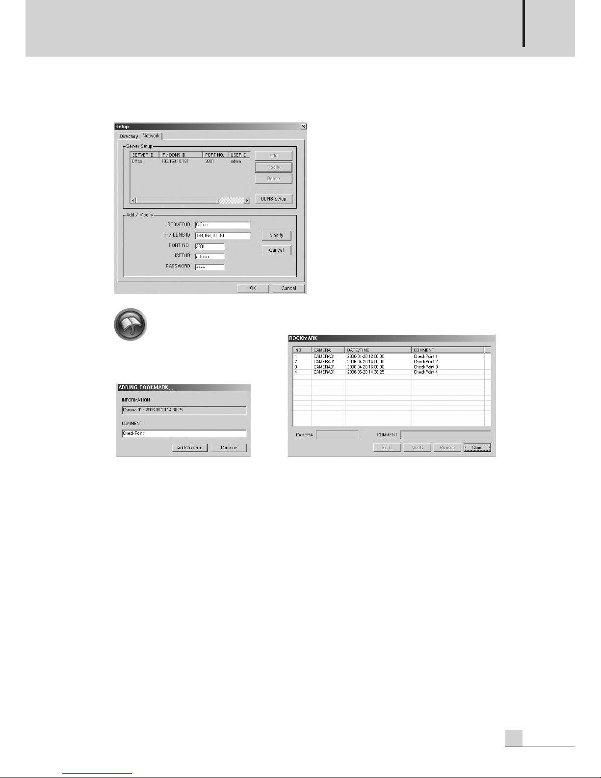
DIGITAL VIDEO RECORDER
57
DSR-815/1608
[ Network Setup ] : Setup network for remote Search.
[DSR-1608/815 does not support Network setup.]
[ Bookmark ] : Function to save and control specific position of recording data.
[Figure. Bookmark 1] [Figure. Bookmark 2]
[ Bookmark Register Sequence ]
- Window is displayed if ‘clicking a bookmark icon’.(Figure. Bookmark 1)
- Information : Displays information (camera number, recording date) of current image.
- Comment : Inputs name of the bookmark capable of identifying bookmark.
- Window is displayed if “clicking” the “Add/Continue” button.(Figure. Bookmark 2)
- Bookmark added to the bookmark list is displayed in the list.
[ Bookmark Find/Control Sequence ]
- Window is displayed if clicking bookmark icon.(Figure. Bookmark 1)
- Window is displayed if clicking “Continue” button.(Figure. Bookmark 2)
- “Click” the bookmark to select from the list.
- “Search” : Searches to image of bookmark currently selected.
(Image is displayed on the image display part.)
- “Modify” : Modify content of bookmark.
- “Remove” : Removes the bookmark selected from the bookmark.
- “Close” : Close the Bookmark Control window.
The bookmark only memorises the location value of a recorded image to manage it. If the storage Device
is saved in overwritten, only the list remains and users and users can no longer see the image.
Page 58

DIGITAL VIDEO RECORDER
58
DSR-815/1608
8. Function Button : This is button of AVI conversion, snap shot, panorama, search setting, book mark and
exit function.
[ AVI Conversion ] : Converts and saves recorded image to dynamic image as AVI file form.
(Below window is displayed if clicking the AVI conversion icon.)
- “...” : Selects file name. (Default file name usable)
- Overlay the Channel Title : Displays channel information on converted data.
- Over the Timestamp : Displays Date information on converted data.
- Compression Type : Selects from “DX50”, “XVID”.
- “Start” : Starts file conversion.
- If starting file conversion, time and size are displayed on list.
- If conversion time ends, click the Stop button.
- “Close” : Close the window.
Page 59

DIGITAL VIDEO RECORDER
59
DSR-815/1608
[ Snap Shot ] : Supports function to save, print, image process and digital zoom.
- “Print” : Prints current figure with a printer.
(For print output, printer must exist in the system.)
- “Save” : Saves current figure in JPG, BMP file.
- “Water mark” : Sets whether function of watermark(prevention of change) will be used.
- “Display channel name” : Sets whether camera name will be displayed.
- “Display captured Time” : Sets whether recording time will be displayed.
- Input File name.
- “Click” the Save button.
- “Digital zoom” : Color Adjustment and displays specific area.
• “Magnify” : Reduces a red square which is area to be magnified.
(magnify the square area image and display it on the same screen)
• “Shrink” : Shrink a red square which is area to be shrunken.
(Shrink the square area image and display it on the central screen)
•”Original size” : Sets image size as initialization value.
- [ Image Process ]
• Brightness : Adjust the brightness of the image.
• Contrast : Adjust the contrast of the image.
• Hue : Adjust the Hue f image.
• Saturation : Adjust the saturation of the image.
• Original Image : Click to restore the default value set in the warehouse
Page 60

DIGITAL VIDEO RECORDER
60
DSR-815/1608
[ Panorama ] : Function to display image in the form of panorama.
❶ Frame Interval: Sets interval between frames.
(Default : 1/30sec [Based on recording of 30 frames per second])
❷ Previous Page : Moves to unit from the overall frame in reverse.
❸ Previous Frame : Moves page by page from the overall frame in reverse.
❹ Reverse Direction Play : Plays in reverse.
❺ Stop : Stops play.
❻ Play in Forward Direction : Play in forward direction.
❼ After Frame : Moves frame by frame forward from the overall frame.
❽ Next Page : Moves page by page forward from the overall frame.
❾ Quit : Quit panorama window.
❶ ❷ ❸ ❹ ❺ ❻ ❼ ❽ ❾
Page 61

DIGITAL VIDEO RECORDER
61
DSR-815/1608
[ Motion (Smart) Search ] : Detects movement in specific area of saved image.
- Start : Button to start motion Search of saved image.
- Motion Area : Sets area to Search from the saved image.
(Area Add : Selects area by dragging with a mouse from the image parts after clicking “Select” button.)
(Area Remove : Removes area by dragging with a mouse from the image parts after clicking “Unselect”
button.)
- Motion Detection : Sets motion detection Rate/sensitivity. [Dull: 0 .... 100 : Sensitive]
- Time Control : Selects time range to Search.
- Automatic : Analyzes data within designated time and automatically generates operation detection list.
- Manual : When detecting a motion, stop to retrieve after adding list.
- Important retrieval matters of motion detection lists are saved at the bookmark list by clicking the “Add”
button. (Must save the bookmark list by clicking the “Apply” button.)
- Search image is displayed on the screen when clicking motion detection lists.
- Immediately moved to main Search screen when double-clicking motion detection lists.
Example of effective Search using this function: It is inconveniently to retrieve all saved times since
you cannot be aware of disappearance if assuming a case that goods laid in specific area of store or
image disappear. This is function to rapidly retrieve time that goods disappear by automatically generating list where motion occurred in the store by checking the area that the goods were laid.
[ Quit ] : Quit Search.
Page 62

DIGITAL VIDEO RECORDER
62
DSR-815/1608
3. IMAGE ANALYSIS
- This program is used to authenticate the forgery or alteration of images in external storages.
- Program execution method : Start menu → All Program → UCM → ETC → “Image Analyst” execution.
- Find - Click “Find” and select an image in JPEG in an external storage.
Page 63

DIGITAL VIDEO RECORDER
63
DSR-815/1608
- Analysis : Open the saved file and click “Analyse” to see if the image is authenticated.
The authenticated Image means that the data in an external device has not altered.
- Authentication Information : If the image has not been forged or altered, the following image should
appear when you check the authentication information. If the image has been altered, the following
information is not displayed.
Page 64

DIGITAL VIDEO RECORDER
64
DSR-815/1608
- Original Image : Click the “Original Image” button to display the following image.
If the image has been altered, all the information is deleted and the following message appears.
Page 65

DIGITAL VIDEO RECORDER
65
DSR-815/1608
Automatic Remote Connect
Automatic Remote Connect
1. AUTOMATIC REMOTE CONNECT AGENTVIEW.
- In installation of UCM program, remote monitoring (AgentView) automatically installed is interlocked with
UCM (client), allowing automatic Connect where event occurs.
- This program operates in interlock with “Network Network Announcement” part in setting of server
program.
- Position of Program : “Windows Start Program UCM Other tools Agent View”
- Agent View icon is displayed in the Announcement Area on the work display line of the window.
- Automatic Connect : Shown a live image through automatic remote Connect to the system where even
occurs in interlock with UCM view.
- Port No : Sets port number of the Agent View.
- Hide : Changes Agent View window to an icon mode.
- End : Ends Agent View program.
- All Delete : Deletes event lists.
- Connect : Remotely Connectes to the system equivalent to the event currently selected.
- Connectes when “double clicking” the event list.
Click Icon
Show the AgentView
Ref) To use remote automatic Connect function, firstly accurately set information concerning network
announcement schedule and network setting of the server program.
Page 66

DIGITAL VIDEO RECORDER
66
DSR-815/1608
2. REMOTE CONNECT SCREEN INTERLOCKED WITH UCM
- This is function automatically Connected by the remote notice schedule in occurrence of event (sensor,
motion).
See UCM manual.(For the detailed, please refer to Page 40.)
Page 67

DIGITAL VIDEO RECORDER
67
DSR-815/1608
Copy (downloadng) data in remote
Copy (downloadng) data in remote
Only an administrator is allowed to utilize this function (Only “ROOT” user).
1) Run the window explorer.(Short key : ”Window Key+E”)
2) Input DSR-1608/815 of ADDRESS with the type of ftp://XX.XX.XX.XX” in the window explorer address.
(Example : ftp://192.168.48.46)
3) On the log on window, input user name and password.
(User name : “root”, password : password of root(the administrator)
Page 68

DIGITAL VIDEO RECORDER
68
DSR-815/1608
4) It will display the folder list playback.
5) Move to the folder which has playback data to search for, and then select a file to be downloaded.
6) Click on the mouse right button and select “Copy to folder” on the menu.
Page 69

DIGITAL VIDEO RECORDER
69
DSR-815/1608
7) Select a folder in which the playback file will be stored. (Folder position: “Drive name.\IMDATA\BACK-
UP\YYYYMMDD”)
(Example. “C:\IMDATA\BACKUP\2007028”)
※ If the file to be downloaded was wrongly nominated, you cannot search for it in search program then.
8) It will copy (download) the playback file selected.
9) When it will have finished to copy (download) the playback file selected, you can search recorded
images in search program.
(For the detailed, please refer to Page 51.)
Page 70

DIGITAL VIDEO RECORDER
70
DSR-815/1608
Specifications
Specifications
* Specifications and design subject to change without notice.
DSR-815 DSR-1608
Camera Input 8 CH (BNC) 16 CH (BNC)
Loop out 8 CH (BNC) 16 CH (BNC)
Monitor Out 1 VGA, 1 BNC (MONITOR OUT)
Camera Input Type NTSC/PAL
Live Speed [NTSC] : Up to 240FPS [NTSC] : Up to 480FPS
[PAL] : Up to 200FPS [PAL] : Up to 400FPS
Recording Speed [NTSC] : Up to 120FPS, [PAL] : Up to 100FPS
Live Resolution [NTSC] : 720x480, [PAL] : 720x576
Recording Resolution [NTSC] : 352x240, 704x480, [PAL] : 352x288, 704x576
Data Size Average 1~3kbyte/Frame (352x240)
Screen Division 1, 4, 8, Auto Switching 1, 4, 9, 16, Auto Switching
Audio Input/Output 4CH /1CH
AutoSwitching Time 1 ~ 30 Sec
Compression MPEG4 ASP MPEG4 ASP
Recording Quality 3 Steps (Normal, Fine, Super-Fine)
Motion Detection Multil-Zones, Multi-Channels, Sensitivity Control
Recording Type Scheduled By Time, Date and Camera
(Continuous, Motion, Sensor, Event, Emergency)
Search Date (Calendar), Time (Mour/Minute/Second), Camera, Smart
User InterFace Graphical user interface, Mouse does support
O/S Embedded Linux
Backup Private Backup, FTP Backup
Sensor Input 8 CH 16 CH
Alarm Output 4 CH
Pan/Tilt Control RS-485 Control
Mouse Mouse does support
USB 2 USB (Front : 1, Rear : 1) [USB 2.0 Support]
Network TCP/IP, DHCP, DDNS, FTP
Network Connection LAN (10/100 Base Ethernet)
Network Transport Speed Max 120FPS
Remote Connection UCM (Display,Recocrd,local Search), Web Viewer through Internet Explorer
WatchDog WatchDog Support
Etc Support mouse/jog/shuttle/remote control/front key.
HDD 250G (Expandable up to max 4 HDD)
Operating Temperature 0°C ~ +40°C
AC Input 100-120V~50Hz/60Hz, 6A / 200-240V~50Hz/60Hz, 4A
Weight (SET) 7kg/15.4lb
Dimensions (SET) 482(W) x 88(H) x 380(D)mm/19(W) x 3.5(H) x 15(D)in
Page 71

DIGITAL VIDEO RECORDER
71
DSR-815/1608
Supplement
Supplement
A. UNDERSTANDING OF DYNAMIC IP
This is method that new Internet IP is assigned whenever starting the system connected with DHCP
(Dynamic Host Configuration Protocol) server, which is not an independent IP fixed to Internet.
To use such a system as an independent server, a middle media server to relay IP changed is required
once in a while, and the system that plays such a role is a DIMS (Dynamic IP Management Server) system.
[ Fixed IP Address ]
[ Dynamic IP Address ]
DSR-1608/815
Client
Dynamic IP Server
Web Server
DSR-1608/815
Client
Page 72

DIGITAL VIDEO RECORDER
72
DSR-815/1608
B. REGISTER FLOW IP SERVER USER
1) Run the internet explorer.
2) Input “http://www.inter-mdvr.co.kr” in the internet address window.
(The following screen will appear.)
3) Click on the area of “DPR/DSR-Series”.
4) Click on the area of “Available after subscription”.
Page 73

DIGITAL VIDEO RECORDER
73
DSR-815/1608
5) Clock on the area of “Member subscription”.
6) Click on the button of “Agree”.
7) Click on the button of “ID check”.
Page 74

DIGITAL VIDEO RECORDER
74
DSR-815/1608
8) Input users’ ID in the test box of “Member ID” and click on the button of “Search”.
(For an available “User ID”, click on the button “OK”.)
(For an unavailable “User ID”, input a new “User ID” and repeat searching to find out an available User
ID.)
Page 75

DIGITAL VIDEO RECORDER
75
DSR-815/1608
9) Input your password, model number, name, e-Mail, and cellular phone number.
“*” After having finished to input all the articles marked *, click on the button of “Member registration”.
⊙ Select a model number : Select your model number. (DPR-1630, DPR-1615, DSR-1608, DSR-815)
⊙ MAC address : Input MAC address of your set.
You can firm MAC address in the MAC address value of the system information.
For the product of (DSR-1608, DSR-815, it is requisite input.)
⊙ e-Mail : Input your e-Mail address currently available.
10) After finishing your member registration, the following message widow will appear.
Click on the button of “OK”.
⊙ Your member registration is completed.
Page 76

DIGITAL VIDEO RECORDER
76
DSR-815/1608
C. INSTALL AN ADDITIONAL HARD DISK (HDD)
Maximum 3 HDDs can be installed in the product. (Available only for HDD of ATA(IDE) type.), [Precautions]
For addition installation of HDDs, please enquire technical experts in your distributor.
[WARNING]
- Unplug the power cord before disassembling.
- Be careful the any cables are wrongly connected or the cladding of a cable is peeled.
- Pay attention not to be injured from a sharp edge in the product inner part.
- Be watchful not to lose screws and parts dissembled.
- If the product does not work on normally having completed to add up HDDs, please contact the service
center.
Procedures of installation of additional HDDs
1. Remove the screws of the right and left part (2 ones in each) and rear part (5 ones).
2. Separate the cover from the product.
3. Disassemble the power supply cable and data(IDE)cable connected to HDD.
Page 77

DIGITAL VIDEO RECORDER
77
DSR-815/1608
4. Remove the bracket screws fixed to HDD.
5. Jumper of the existing HDD must be installed with Primary Master.
- In case for adding up one HDD:
• Existing HDD Jumper : Master of Primary
• For HDD Jumper newly added : Slave of Primary
- In case for adding up two~three HDD :
• Existing HDD Jumper : Master of Primary
• For HDD _1 Jumper newly added : Slave of Primary
• For HDD _2 Jumper newly added : Master of Secondary
• For HDD _3 Jumper newly added : Slave of Secondary
[WesterDigital Harddisk jumper]
6. Fix up new HDD on the bracket with screws.
Jumper Setting
IDE Connector
Jumper
Power Connector
Page 78

DIGITAL VIDEO RECORDER
78
DSR-815/1608
7. Fix up Bracket on the Holes of Case wite screws.
8. Connect the power supply cable and data(IDE)cable to HDD.
9. Fix up the connectors and wiring in the inner part with ties and close the cover.
10. Fix up the cover with fixing screws. (Left and right parts (2 points in each and rear part (5 points)
※ For the installation method per manufacturer, please refer to Operating Instructions of HDD.
※ We recommend you HDD to be newly added will be the same series of an existing HDD.
※ When HDD Jumper and data cable are abnormally connected, the system cannot recognize a HDD, or it
does not go on, please contact the service center.
Page 79

DIGITAL VIDEO RECORDER
79
DSR-815/1608
D. RECORDING TIME TABLE
Unit: [Day]
Resolution Codec Data Size
HDD 1FPS 2FPS 3FPS 5FPS 7.5FPS
160G 88.8 44.4 29.6 17.76 11.84
MPEG4
200G 111 55.5 37 22.2 14.8
Normal
250G 138.75 69.375 46.25 27.75 18.5
L 320G 177.6 88.8 59.2 35.52 23.68
400G 222 111 74 44.4 29.6
500G 277.5 138.75 92.5 55.5 37
160G 38.556 25.704 17.136 11.424 7.616
MPEG4
200G 48.195 32.13 21.42 14.28 9.52
Fine
250G 60.24375 40.1626 26.776 17.85 11.9
M 320G 77.112 61.408 34.272 22.848 15.232
400G 96.39 64.26 42.84 28.56 19.04
500G 120.4875 80.325 53.55 35.7 23.8
160G 21.792 10.896 7.264 4.3584 2.9056
MPEG4
200G 27.24 13.62 9.08 5.448 3.632
Super
250G 34.05 17.025 11.35 6.81 4.54
H 320G 43.584 21.792 14.528 8.7168 5.8112
400G 54.48 27.24 18.16 10.896 7.26
500G 68.1 34.05 22.7 13.62 9.08
160G 22.2 11.1 7.4 4.44 2.96
MPEG4
200G 27.75 13.875 9.25 5.55 3.7
Normal
250G 34.6875 17.34375 11.5625 6.9375 4.625
L 320G 44.4 22.2 14.8 8.88 5.92
400G 55.5 27.75 18.5 11.1 7.4
500G 69.375 34.6875 23.125 13.875 9.25
160G 9.639 6.426 4.284 2.856 1.904
MPEG4
200G 12.04875 8.0325 5.355 3.57 2.38
Fine
250G 15.06094 10.04063 6.69375 4.4625 2.975
M 320G 19.278 12.852 8.568 5.712 3.808
400G 24.0975 16.065 10.71 7.14 4.76
500G 30.12188 20.08125 13.3875 8.925 5.95
160G 5.448 2.724 1.816 1.0896 0.7264
MPEG4
200G 6.81 3.405 2.27 1.362 0.908
Super
250G 8.5125 4.25625 2.8375 1.7025 1.135
H 320G 10.896 5.448 3.632 2.1792 1.4528
400G 13.62 6.81 4.54 2.724 1.816
500G 17.025 8.5125 5.675 3.405 2.27
352
X
240
704
X
480
Page 80

DIGITAL VIDEO RECORDER
80
DSR-815/1608
E. RECORDING SIZE AND RECORDING SIZE CALCULATION METHOD
1. It is calculated based on continuous recording mode, and recording time will be longer in the mode of
motion and sensor.
2. It is based on normal recording condition and possible to cause different recording time depending on
situation.
3. In case of recording both audio and video at the same time, the time of it will be shorten.
4. Recording time calculation method
- In case of 250GB HDD, it allows 237G for recording
- system files for ReCycle Recording 3G
5. Daily Recording method :
(CH recording frame No.xCH No.)xfile size(K)x60secx60minx24hour Example) CIF, Modified
MPEG4, Low, File size 1k, 240 frame recording 120FPSx1Kx60secx60secx24hours = 10.4G
6. 250G HDD Recording time calculation :
Total 250G recording size/Total recording frame (CH recording frame No.xCH No)/File size(K)/
60sec/60min
Example) CIF, Modified MPEG4, Normal, file size 2K, 120frame recording
237,000,000,000Byte/120FPS/2K/60sec/60min = 274.3hours(Divide 24hour = 11.43day)
Page 81

79
DSR-815/1608
NOTE
Page 82

2
DSR-815/1608
NOTE
Page 83

3
DSR-815/1608
Page 84

MADE IN KOREA
www.inter-m.com
2008. 1 9000003320
 Loading...