

Page 1

Operation Manual
Digital SR Amplifier
DSA-100D/DV
Page 2

DIGITAL SR AMPLIFIER
Welcome
Welcome
A personal welcome to you from the management and employees of Inter-M
All of the co-workers here at Inter-M are dedicated to providing excellent products with inherently good value,
and we are delighted you have purchased one of our products.
We sincerely trust this product will provide years of satisfactory service, but if anything is not to your complete
satisfaction, we will endeavor to make things right.
Welcome to Inter-M, and thank you for becoming part of our worldwide extended family!
This symbol is int ended to ale rt the user to the
CAutION
RISK OF ELECTRIC SHOCK
DO NOT OPEN
CAUTION: TO REDUCE THE RISK OF ELECTRIC SHOCK.
DO NOT REMOVE COVER (OR BACK).
NO USER-SERVICEABLE PARTS INSIDE.
REFER SERVICING TO QUALIFIED SERVICE PERSONNEL.
Caution: To prevent electric shock do not use this (polarized) plug with
Attentions: Pour prévenir les chocs électriques ne pas utiliser cette
WARNING
To prevent fire or shock hazard, do not
expose the unit to rain or moisture.
*WARNING FOR YOUR PROTECTION PLEASE READ THE FOLLOWING-WATER AND MOISTURE: Unit should not be used near water(e.g.
near a bathtub, washbowl, kitchen sink, laundry tub, in a wet basement, or near a swimming pool, etc). Care should be taken so than objects do
not fall and liquids are not spilled into the enclosure through openings.
*CLASS 2 WIRING (Adjacent to speaker terminal): The speaker output of this apparatus can exceed 10 Watts and could be a shock injury.
Connection to speakers should be performed by a skilled person.
*Do not install this equipment in a confined space such as a book case or similar unit.
*This apparatus shall not be exposed to dripping or splashing and no objects filled with liquids, such vases, shall be placed on the apparatus.
*This apparatus shall be connected to a mains socket outlet with a protective earthing connection.
It has heed to be easy to disconnect the device. To disconnect the device from power, separate AC input cable from inlet or unplug the AC Cord.
*
CAutION
*These servicing instructions are for use by qualified service personnel only. To reduce the risk of electric shock, do not perform any servicing
other than that contained in the operating instructions unless you are qualified to do so.
NOtE
*This equipment has been tested and found to comply with the limits for a Class A digital device, pursuant to Part 15 of the FCC Rules. These limits are
designed to provide reasonable protection against harmful interference when the equipment is operated in a commercial environment. This equipment
generates, uses, and can radiate radio frequency energy and, if not installed and used in accordance with the instruction manual, may cause harmful
interference to radio communications. Operation of this equipment in a residential area is likely to cause harmful interference in which case the user will
be required to correct the interference at his own expense.
presence of uninsulated “dangerous voltage” within
the product’s enclosur e that ma y be of sufficient
magnitude to constitute a risk of electric shock to
persons.
This symbol is int ended to ale rt the user to the
presence of important operation and maintenance
(servicing) instructions in the literature accompanying
the appliance.
an extension cord, receptacle or other outlet unless the blades
can be fully inserted to prevent blade exposure.
fiche polarisée avec un prolongateur, une prise de courant
on une autre sortie de courant, sauf si les lames peuvent
étre inséré es à fond sans en lai sser aucune par tie à
découvert.
Page 3

DIGITAL SR AMPLIFIER
Contents
Contents
Unpacking .......................................................................................................................................2
Installation
Environment....................................................................................................................................2
Important Safety Instructions.............................................................................................................2
Features............................................................................................................................................3
Front Panel ......................................................................................................................................4
Rear Panel .......................................................................................................................................6
Installation of Caution ...................................................................................................................9
Applications ..................................................................................................................................10
Block Diagram ..............................................................................................................................11
Specifications ................................................................................................................................13
How to install the rack ................................................................................................................17
Service............................................................................................................................................17
Warranty .......................................................................................................................................17
DSA-100D/DV
1
Page 4

DIGITAL SR AMPLIFIER
Unpacking
Unpacking
Although your DSA-100D/DV is neither complicated nor difficult to operate, we recommend you take a few
minutes to read this brief manual and familiarize yourself with the important information regarding product
features, setup and operation.
As with most electronic devices, we strongly recommend you to retain the original packaging. In the unlikely
event the product must be returned for servicing, the original packaging (or reasonable equivalent) is required.
Installation
Installation
Environment
Never place this product in an environment which could alter its performance or reduce its service life. Such
environments usually include high levels of heat, dust, moisture, and vibration.
IMPORTANT SAFETY INSTRUCTIONS
1. Read these instructions.
2. Keep these instructions.
3. Heed all warnings.
4. Follow all instructions.
5. Do not use this apparatus near water.
6. Clean only with dry cloth.
7. Do not block any ventilation openings. Install in accordance with the manufacturer’s instructions.
8. Do not install near any heat sources such as radiators, heat registers, stoves, or other apparatus (including
amplifiers) that produce heat.
9. Do not defeat the safety purpose of the polarized or grounding-type plug. A polarized plug has two blades
with one wider than the other. A grounding type plug has two blades and a third grounding prong. The wide
blade or the third prong are provided for your safety. If the provided plug does not fit into your outlet, consult
an electrician for replacement of the obsolete outlet.
10. Protect the power cord from being walked on or pinched particularly at plugs, convenience receptacles, and
the point where they exit from the apparatus.
11. Only use attachments/accessories specified by the manufacturer.
12. Use only with the cart, stand, tripod, bracket, or table specified by the manufacturer, or sold with the apparatus.
When a cart is used, use caution when moving the cart/apparatus combination to avoid injury from tip-over.
13. Unplug this apparatus during lightning storms or when unused for long periods of time.
14. Refer all servicing to qualified service personnel. Servicing is required when the apparatus has been
damaged in any way, such as power-supply cord or plug is damaged, liquid has
been spilled or objects have fallen into the apparatus, the apparatus has been
exposed to rain or moisture, does not operate normally, or has been dropped.
2
DSA-100D/DV
S3125A
Page 5

DIGITAL SR AMPLIFIER
Features
Features
- Compact Design
The DSA Series is a amplifier 100 watts x 2 of Power that is housed in half rack 1 RU compact chassis. Ideal
for applications where high power stereo amplification is required such as board room and class rooms.
- Professional Grade D-Class Amplifier and Switch Mode Power Supply (SMPS)
Class D amplifier offer improved total harmonic distortion with an increased signal to noise ratio of
professional grade sound quality. SMPS creates a high efficiency amplifier offering reduced power
consumption and low heat dissipation.
- APD (Auto Power Down)
The amplifiers automatically enter into a standby mode after 30 min when unit is not in active, it takes a
advantage of reducing power consumption.
The unit returns to operating status within 3 sec upon signal detection.
- ENERGY STAR - Low Power Compsumtion in STAND BY mode
In STAND BY mode, the unit only takes a less than 1W of electric power compsumtion which complies
with ENERGY STAR® standards.
- GAIN selection switch
Selectable proper input sensitivity of amplifier either +4dBu (1.2283V) or -20dBu (77.5mV)
- High Pass Filter (120Hz)
Built in High Pass Filter to protect the speaker against unwanted low frequency.
- Bridge-Mono Mode
Bridging allows power to be output at 200 watts.
- Power Mode Selection Switch
There are 3 selectable power mode switch (ON/REMOTE/OFF). When switch is selected as REMOTE, the
amplifiers can be remotely power ON/OFF control.
- Remote Power Connector
The remote power allows the amplifier to be turned on or off from a distance or other device via dry contact
closure.
- Front siganl and protection LED indicators
LED indicators for POWER, STAND BY, PROTECTION, SIGNAL and CLIP on the front panel give a easy
verification of operation status.
- Advanced Protection Circuitry
Advanced protection circuitry guards against overheating, shorted outputs, DC output, overloads.
- Balanced Input
This connection is used to ensure the lowest noise operation which eliminates the common noise from the cable.
- VCA (Voltage Control Amplifier) Control (Only DSA-100DV)
Voltage-controlled amplifier is an electronic amplifier that varies its gain depending on a control voltage. These
two terminals provide connection for an external potentiometer. When the potentiometer is connected, it allows
for remote control of the master volume level.
Note that individual input volume control positions limit the maximum output level adjustable with the remote
volume control.
DSA-100D/DV
3
Page 6
DIGITAL SR AMPLIFIER
M
IN MAX
CH 2CH 1
CLIP
M
IN MAX
P
ROT POWER
STAND BY
SIG
D
SA
D
IGITAL SR AMPLIFIER
100D
1 3
2
4 5
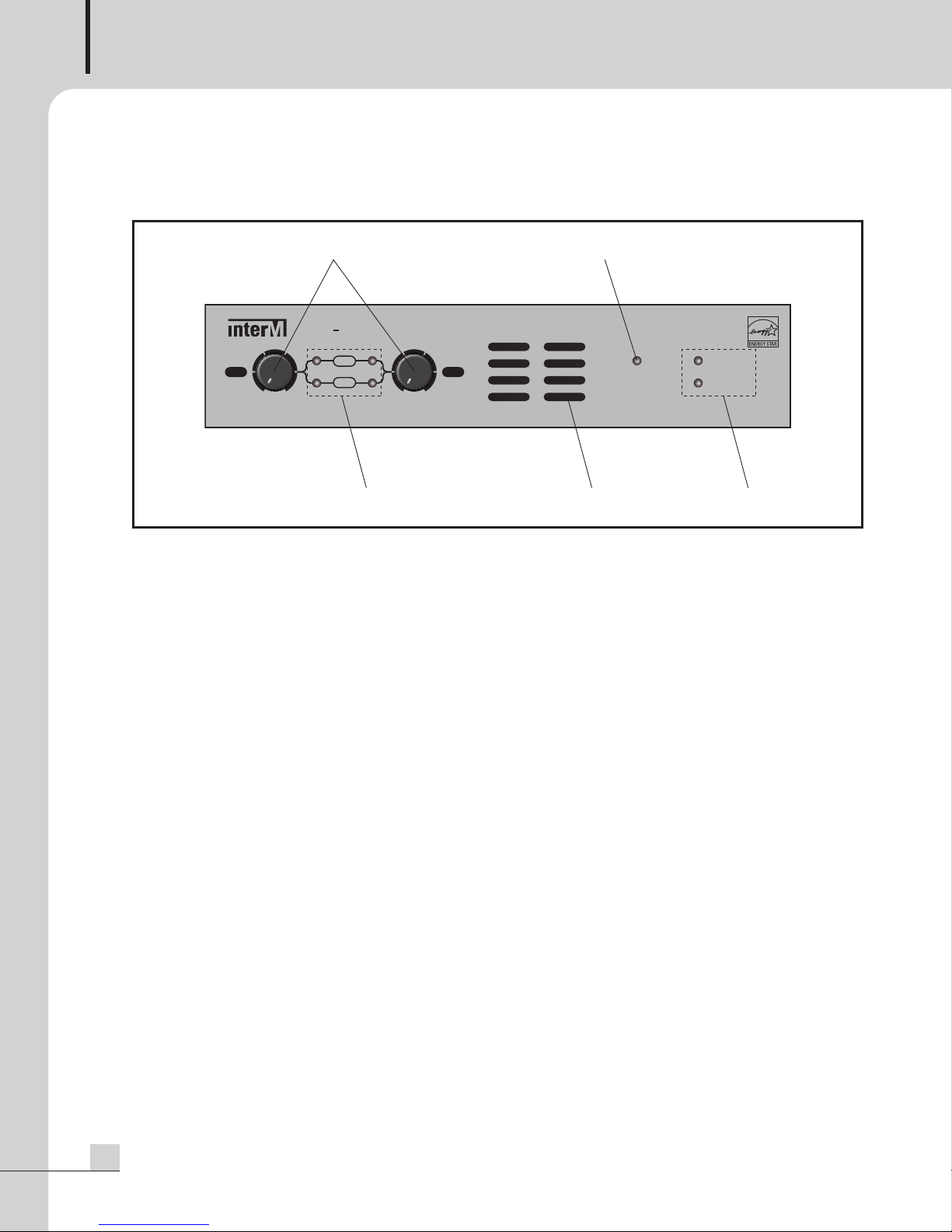
Front Panel
Front Panel
1. VOLUME CONTROL
Turn the volume controls clockwise to increase gain and counterclockwise to decrease gain against each
channel.
2. OUTPUT SIGNAL LEVEL INDICATORS
The LEDS indicate the amplifier’s output signal levels.
- SIGNAL LED Illuminates green when signal is present at the input more then -25dB.
- CLIP LED illuminates red when there are excessive signal levels.
※ NOTE : The Cliping may damage the speakers and amplifier so when CLIP LED is on please lower the
volume level.
3. PROTECTION MODE INDICATOR
The amplifier features several types of protection circuitry to prevent damage during power-up or fault
conditions such as overheat, overload and a detection of DC output. PROTECTION LED illuminates when
any of these faults is detected. The output relays will disconnect the speaker loads when the protection
circuitry detects a fault condition. Once the specific fault has been corrected, the PROTECTION LED will be
turned off and The unit will be working normally.
Protect LEDs will illuminate for 2 to 3 sec during power-up process then after 2 to 3 sec PROTECTION LED
will be turned off and stay as normal condition to use.
4. COOLING VENTS
Air flow is front to back. DO NOT block front or rear air vents.
4
DSA-100D/DV
Page 7

DIGITAL SR AMPLIFIER
5. POWER LED INDICATOR
- POWER LED illuminates green when the rear power selection switch is selected as ON or the remote power
contact is triggered when the rear power selection switch is selected as REMOTE.
The unit turns into APD (Auto Power Down) mode, the power LED will turns off.
- STAND BY LED illuminates yellow when the rear power selection switch is selected as OFF or the remote
power contact is not triggered when the rear power selection switch is selected as REMOTE.
● APD (Auto Power Down) function
①
when the rear power selection switch is selected as ON or
②
when the rear power selection switch is selected as REMOTE and the remote power contact is not triggered,
it will activate the APD mode.
- POWER LED illuminates green until APD mode is on under that circumstance.
- The amplifiers automatically enter into a standby mode after 30 min of inactivity then STANBY LED will
illuminates yellow which helps to minimumize the electric power consumption.
- The unit returns to operating status within 3 sec upon signal over -30dB detection, STAND BYE LED will be
off and POWER LED will illuminates green.
DSA-100D/DV
5
Page 8

DIGITAL SR AMPLIFIER
1 23
5 6 7 8 9 10
4
INPUT 1
A
C INPUT
S
PEAKER OUT
REMOTE
POWER
VCA CONTROL
2CHBRIDGE
V1
C1GC2V2
MODE
ONOFF
HPF
+
4dBu
-
2
0dBu
GAIN
O
FF
R
EMOTE
O
N
POWER
CLASS 2 WIRING
G
INPUT 2
G
CH 24Ω 4Ω
8
Ω
CH 1
B
RIDGE
SPEAKER OUT
4Ω 4Ω
SPEAKER OUT
8Ω
CH 24Ω 4Ω8ΩCH 1
BRIDGE
CH 24Ω 4Ω
8
Ω
CH 1
B
RIDGE
Rear Panel
Rear Panel
1. AC INLET
It accepts a standard IEC mains cable, provided.
2. COOLING VENTS
Air flow is front to back. DO NOT block front or rear air vents.
3. SPEAKER OUTPUT TERMINAL
Operation Mode
Minimum Speaker Impedance
2 Channel
Bridged
Speaker connection of CH1/CH2 or Bridge mode. (see below picture)
2 Channel Bridge
6
DSA-100D/DV
4Ω
8Ω
※ NOTE
When use bridged mode,
please set MODE switch as
‘BRIDGE’ and connect input
on ‘INPUT 1’.
Page 9

DIGITAL SR AMPLIFIER
INPUT 1
AC INPUT
S
PEAKER OUT
REMOTE
POWER
VCA CONTROL
2
CHBRIDGE
V
1
C
1GC2V2
MODE
O
NOFF
HPF
+4dBu
-
20dBu
G
AIN
OFF
R
EMOTE
ON
POWER
C
LASS 2 WIRING
G
INPUT 2
G
C
H 24Ω
4
Ω
8Ω
C
H 1
BRIDGE
Bridge connection: wire the “hot”/positive lead to the “+” terminal of CH1, the “common”/negative lead to
he “-” terminal of CH2.
t
※ NOTE : Before connecting speakers to the unit, be sure to disconnect the AC power cable. Make certain
that the total impedance is not less than the rated impedance indicated.
Do not put the speaker cable close to input signal cable.
4. VCA (VOLTAGE CONTROLLED AMPLIFIER) TERMINAL (Only DSA-100DV)
When the potentiometer is connected, it allows for remote control of the master volume level.
CH1 remote volume : connect into "V1, C1, G" with 10kΩ volume (B curve type)
CH2 remote volume : connect into "V2, C2, G" with 10kΩ volume (B curve type)
Connections of VCA control terminal. (see below picture)
* VCA (VOLTAGE CONTROL AMPLIFIER)
Voltage-controlled amplifier is an electronic amplifier that varies its gain depending on a control voltage.
These two terminals provide connection for an external potentiometer. When the potentiometer is
connected, it allows for remote control of the master volume level without sound distortion.
※ NOTE : Note that individual input volume control positions limit the maximum output level adjustable with
the remote volume control
If VCA control unit is seperated from the unit, it goes back to level of front panel volume control
so do not separate the VCA control unit while it is in use.
5. POWER MODE SELECTION SWITCH
- There are 3 selectable power mode switch. (ON/REMOTE/OFF)
- Switches to ON : Power ON
- Switches to OFF : Power OFF
- Switches to REMOTE and Remote power connector is triggerd : Power ON
- Switch to REMOTE and Remote power connector is not triggerd : Power OFF
6. REMOTE POWER CONNECTOR
Power Mode switch is
selects as REMOTE and Remote power connector is triggerd : Power ON
selects as REMOTE and Remote power connector is not triggerd : Power OFF
DSA-100D/DV
7
Page 10

DIGITAL SR AMPLIFIER
. MODE SWITCH
7
Mode selection switch for either CH1/CH2 stereo or BRIDGE mono mode
(1) CH1/CH2 MODE
Input signal of each channel will drive each channel independently. Input signal of CH1 drives Amp
output of CH1, Input signal of CH2 drives Amp output of CH2. In this case volume can be controlled
independently on both channel.
(2) BRIDGE MODE
The bridge mono mode combines both channels to create one larger mono channel.
By connecting CH1 (+) terminal and CH2 (-) terminal, The amplifier will deliver approximately twice the
voltage at CH1. Please observe the minimum load specification when operating in Bridge mode.
※ NOTE : In BRIDGE mode, Do not use the CH2 input because only CH1 input is active and put the CH2
volume control to minimum position which only volume will controlled by CH1 volume control.
In BRIDGE mode the speaker impedance load must be atleast 8Ω.
※ NOTE : When connected to the OPT-100D, set the mode switch to "2CH".
(The OPT-100D DO NOT support the bridged mode.)
8. HIGH PASS FILTER SWITCH (ON/OFF)
Select swich position to ON, it will activate 120Hz -12dB / OCT High Pass Filter.
※ NOTE : When connected to the OPT-100D, set the HPF switch to "ON".
※ NOTE : High Pass Filter is to increase sound clarity and improve output sound.
9. GAIN SELECTION SWITCH
Select proper input sensitivity of amplifier either +4dBu (1.2283V) or -20dBu (77.5mV)
※ NOTE : The -20dBu is designed for low level device of audio source. If you connect the a general audio
device (such as CD, TUNER, DECK ect) and set up the -20dBu together, the quality of sound may
be deteriorated.
10. INPUT TERMINAL
These inputs are balanced and configured as follows: + (signal plus), - (signal minus), GND (ground)
※ NOTE : Connect or disconnect input terminal after unpluging the power cord.
8
DSA-100D/DV
Page 11

DIGITAL SR AMPLIFIER
(Side)
Front
Front Inhalation
R
ear Vent
Rear Open
INPUT 1
A
C INPUT
S
PEAKER OUT
R
EMOTE
P
OWER
VCA CONTROL
2CHBRIDGE
V
1
C1GC2V2
MODE
ONOFF
HPF
+
4dBu
-
2
0dBu
G
AIN
OFF
REMOTE
ON
POWER
CLASS 2 WIRING
G
INPUT 2
G
C
H 24Ω4Ω
8
Ω
C
H 1
B
RIDGE
Installation of Caution
installation of Caution
The Cooling Vents are provided for ventilation and to ensure reliable operation of the unit and to protect it from
overheating. These openings must not be blocked or covered. The unit should not be placed in a built-in
installation unless proper ventilation is provided.
Maintain a minimum distance of 2 inch (50 mm) around the front, the rear, and the sides of the unit for
Front
Front
Less than 10cm
DSA-100D/DV
9
Page 12

DIGITAL SR AMPLIFIER
INPUT 1
AC INPUT
SPEAKER OUT
REMOTE
POWER
VCA CONTROL
2CHBRIDGE
V1
C1GC2V2
MODE
ONOFF
HPF
+4dBu-20dBu
GAIN
OFF
REMOTE
ON
POWER
CLASS 2 WIRING
G
INPUT 2
G
CH 24Ω 4Ω8ΩCH 1
BRIDGE
DSA-100D/DV
MIXER
SPEAKER
CD PLAYER
INPUT 1
AC INPUT
SPEAKER OUT
REMOTE
POWER
VCA CONTROL
2CHBRIDGE
V1
C1GC2V2
MODE
ONOFF
HPF
+4dBu-20dBu
GAIN
OFF
REMOTE
ON
POWER
CLASS 2 WIRING
G
INPUT 2
G
CH 24Ω 4Ω8ΩCH 1
BRIDGE
DSA-100D/DV
MIXER
SPEAKER
CD PLAYER
Applications
Applications
Stereo Installation
2 Channel Mode
Bridged Mono Installation
Bridged Mode
※ Please set MODE switch as ‘BRIDGE’ and connect input on ‘INPUT 1’, When use Bridged mode.
10
DSA-100D/DV
(Check ‘7. MODE SWITCH’ on ‘Rear Panel’ for detailed setting particulars.)
Page 13

Block Diagram
P
F
C
M
A
I
N
P
OWE
R
(AC-D
C)
CI
RCUI
TCIRCUIT
SP
K
R
L
Y
CON
TR
OL
S
T+
15
V
ST-15V
F
AN
THERM
A
L
SE
N
SOR
2
TH
E
R
M
AL
SE
NS
O
R
1
F
AN
CO
N
TR
O
L
C
L
IP
L
E
D
SIG
L
ED
CL
I
P
L
E
DSIG
L
E
D
SP
E
AK
E
R
R
E
L
AY
B
R
I
-
BR
I
+
CH2
SP
K
+
CH
2
SP
K
-
C
H1
S
P
K
+
CH
1
SP
K
-
BRIDGE
2
C
H
M
OD
E
s
w
i
t
c
h
-I
N
+I
N
HPF
sw
i
t
c
h
1
2
0Hz 12d
B
/oct
L
PF
HP
F
s
w
i
t
ch
120H
z
12
d
B
/
o
c
t
-
20d
B
u (77
.5
m
v
r
m
s
)
G
AIN
swi
t
ch
+4dBu (1.2283vrms)
-
20
dB
u
(
77.
5m
vrm
s
)
G
AIN
swit
c
h
P
ROT
CI
R
CU
IT
(20~
3
0 MIN
)
L
PF
D
CP
OTP
P
R
O
T
L
ED
POWE
R
SELECT
s
witchR
EM
O
TE
P
O
W
E
R
P
OWER C
O
N
TR
O
L
ON
L
ED
STBY
L
E
D
ST5V
B+
+15V
-15V
B-
AC
I
N
STBY
P
O
W
E
R
COU
N
TER
S
I
G
N
AL
SENSIN
G
D
-
A
MP
HP
F
DIFF AMP
D
-
AM
P
H
P
F
D
IF
F
A
M
P
+
-
G
A
NCE
D
I
N
P
U
T
+
-
G
A
L
AN
C
ED I
N
P
U
T
C
H1 IN
+
4
dBu
(
1.228
3
vr
m
s)
S
T+
15V/
S
T
-15V
ST
5
VST
5VST5V
ST+15V/ST-1
5V
ST5V
Block Diagram
DSA-100D
DIGITAL SR AMPLIFIER
DSA-100D/DV
11
Page 14

DIGITAL SR AMPLIFIER
P
F
C
M
A
IN
P
O
WE
R
(AC
-
D
C)
C
I
R
CUIT
CIRCUIT
SP
K
R
L
Y
C
ONTR
O
L
ST+1
5
V
ST-15V
F
A
N
THE
R
M
AL
SENSOR
2
TH
E
R
M
A
L
SE
NSO
R
1
F
A
N
CO
N
TRO
L
CL
I
P
L
ED
S
I
G
L
E
D
CL
I
P
L
EDS
I
G
L
E
D
SP
E
A
K
E
R
RE
L
AY
B
R
I
-
BR
I
+
C
H
2
SPK
+
CH
2 S
P
K
-
CH1
S
P
K
+
CH1 S
P
K
-
BR
I
D
G
E
2
CH
M
O
D
E
s
w
i
t
ch
-I
N
+IN
c
o
ntr
ol
V
C
A
HPF
s
w
it
c
h
12
0Hz
12d
B/oct
c
o
n
t
r
ol
V
C
A
LP
F
H
PF
s
w
itc
h
12
0Hz
12d
B/
o
ct
-
20d
Bu
(7
7.
5m
v
r
m
s
)
G
A
I
N
swi
t
ch
+4d
B
u
(
1.2
28
3
vr
m
s
)
-
20
d
B
u
(
7
7.5m
v
r
m
s
)
G
AIN
s
w
i
t
c
h
P
R
O
T
CI
R
CU
I
T
(2
0
~3
0
MI
N
)
L
P
F
D
CP
O
TP
P
R
O
T
L
E
D
POWE
R
SE
LE
CT
sw
i
t
ch
R
E
M
O
TE
P
O
W
E
R
POWE
R
C
O
N
TR
O
L
ON
LED
S
TB
Y
L
E
D
ST5
V
B
+
+15V
-1
5
V
B
-
A
C I
N
STBY P
O
W
E
R
C
O
U
NT
E
R
SI
G
N
A
L
S
E
N
SIN
G
D
-A
M
PHPF
D
IFF
AM
P
D
-A
M
PHP
F
D
IFF
AMP
+
-
G
AL
ANCED
IN
P
UT
H2
IN
+
-
G
L
AN
C
E
D
IN
PUT
C
H
1
IN
+
4d
Bu
(1.
2
2
83v
r
ms)
ST+15V/ST-15V
ST5VS
T
5V
ST
5
V
ST+15V/ST-15V
ST
5
V
Block Diagram
Block Diagram
DSA-100DV
12
DSA-100D/DV
Page 15

Specifications
Specifications
DIGITAL SR AMPLIFIER
DSA-100DDSA-100DV
20kHz LPF,
Rated Output
Power
Peak Power Bridged 4Ω1kHz 10cycle 280W
Input
Sensitivity
Damping Factor 1KHz, Rated Output Power @ 8Ω110
THD + N
S/N 20kHz LPF, AUX-0025, A-WTD. 93dB 92dB
Frequency
Response
AUX-0025.
@ 1kHz.
@ THD + N = 1%.
20kHz LPF,
AUX-0025.
@ 1kHz.
20kHz LPF,
AUX-0025.
@ 1kHz.
@ 10dB Below Rated
Output
Power
INPUT 1.2283 vrms.
VOLUME Adjust.
2 Channel
Bridged 8ΩMore than 200W
GAIN SWITCH +4dBu(1.2283V)
GAIN SWITCH -20dBu(77.5mV)
2 Channel
10dB Below
2 Channel
10dB Below
Bridged
10dB Below
2
Channel Output
±1dB
4ΩMore than 100W
8ΩMore than 55W
+4dBu± 2dB
-20dBu± 2dB
4Ω1kHz 0.02% 0.03%
8Ω1kHz 0.02% 0.03%
8Ω1kHz 0.02% 0.03%
1W / 8Ω
20Hz~20kHz
HPF
Channel
Separation
Operation Temperature / Humidity -10℃~ +40℃/ 0% ~ 90%
Power Source 100-240VAC, 50/60Hz
Power Consumption (1/8 Rated Output Power @4Ω) 45W
STAND BY Power Consumption Less than 1W
Weight(set) 2.5kg/5.5lb
Dimensions(set)
* Specifications and design subject to change without notice.
INPUT 1.2283 vrms.
VOLUME Adjust.
20kHz LPF,
AUX-0025.
@ 3dB Beloaw
Rated Output Power
2 Channel Output
1W / 4Ω
Channel Output
3dB Below
120Hz -3dB ± 2dB (-12dB / oct)
1kHz -65dB
210(W) x 44(H) x 280(D)mm
8.3(W) x 1.73(H) x 11(D)in
DSA-100D/DV
13
Page 16

DIGITAL SR AMPLIFIER
177
210
5 44
280
※ DIMENSIONS
14
DSA-100D/DV
Page 17

How to install the rack
.YNN
.YNN
.YNN
.YNN
%4"%%7
#,5%4"%)
5BLFGFFUTPGGOFBS'SPOU1BOFM
*OTUBMM3BDLNPVOU#,5VTJOH.TDSFXT
How to install the rack
AMP & BLANK MOUNT
DIGITAL SR AMPLIFIER
DSA-100D/DV
15
Page 18

DIGITAL SR AMPLIFIER
.YNN
.YNN
%4"%%7
#,5%4"%)
.YNN
.YNN
.YNN
5BLFGPPUTPGG
*OTUBMM#,5VTJOH.4DSFX
%4"%%7
015%PS%4"%%7
.YNN
.YNN
3&"3+0*/5#,5
4&5#,5
#,5%4"%'
5BLFGFFUTPGGOFBS'SPOU1BOFM
*OTUBMM3BDLNPVOU#,5VTJOH.TDSFXT
5BLFGFFUTPGGOFBS'SPOU1BOFM
*OTUBMM3BDLNPVOU#,5VTJOH.TDSFXT
AMP & OPT RACK MOUNT
16
DSA-100D/DV
Page 19

DIGITAL SR AMPLIFIER
Service
Service
Procedures
Take steps to insure the problem is not related to operator error or other products within the system. Information
provided in the troubleshooting portion of this manual may help with this process. Once it is certain that the
problem is related to the product contact your warranty provider as described in the warranty section of this
manual.
Schematic
A Schematic is available by contacting your warranty provider.
Parts List
A Parts List is available by contacting your warranty provider.
Warranty
Warranty
Warranty terms and conditions vary by country and may not be the same for all products. Terms and conditions
of warranty for a given product may be determined first by locating the appropriate country which the product
was purchased in, then by locating the product type.
To obtain specific warranty information and available service locations, contact Inter-M directly or the
authorized Inter-M Distributor for your specific country or region.
DSA-100D/DV
17
Page 20

Inter-M, Ltd. (Korea) began operations in 1983.
Since then, Inter-M has grown to become one of the largest manufacturers
of professional audio and commercial sound electronics equipment in the world.
Inter-M has gained worldwide recognition for its own branded products,
as well as private label manufacturing of electronics sold under other names (OEM).
The company is no longer just a Korean company, but rather a global company
that is truly international in scope, with factories and offices in Korea and China,
and sales and marketing operations located in Japan, Europe, and the U.S.A.
With more than 850 employees around the globe,
Inter-M is well-poised for further growth and expansion.
Inter-M Americas, Inc.
13875 Artesia Blvd. Cerritos, CA 90703 USA
TEL : +1-562-921-0313, FAX : +1-562-921-0370
Home Page : http://www.inter-m.net, E-mail : info@inter-m.net
Inter-M Corporation
Seoul OFFICE:653-5 BANGHAK-DONG, DOBONG-GU, SEOUL, KOREA
TEL : +82-2-2289-8140~8, FAX : +82-2-2289-8149
Home Page : http://www.inter-m.com, E-mail : overseas@inter-m.com
MADE IN KOREA
July 2013 133444
 Loading...