

Page 1
P/N 466-
2520 • REV I • ISS 02NOV16
Page 2
Copyright
©
2016 UTC Fire & Security Americas Corporation, Inc.
All rights reserved.
This document may not be copied in whole or in part or otherwi se
reproduced without prior written consent from
UTC Fire & Security
Americas Corporation, Inc.
, except where specifically permitted under US
and international copyright law.
Trademarks and
patents
ZeroWire
name is a trademark of UTC Fire & Security Americas
Corporation, Inc.
IOS is the registered trademark of
Cisco Technology, Inc.
Android, Google and Google Play are registered trademarks of Google Inc.
iPhone, Apple, iTunes are registered trademarks of Apple Inc.
App Store is a service mark of Apple Inc.
Other trade names used in this document may be trademark
s or registered
trademarks of the manufacturers or vendors of the respect i ve products.
Manufacturer
Placed on the market by:
UTC Fire & Security Americas Corporation, Inc.
3211 Progress Drive, Lincolnton, NC, 28092, USA
Authoriz
ed EU manufacturing representative:
UTC Fire & Security B.V.
Kelvinstraat 7, 6003 DH Weert, Netherlands
Certification
EN 50131
-1 System requirements
EN 50131
-3 Control and indicating equipment
EN 50131
-6 Power Supplies
Security Grade 2, Environmental
class II
EN50136
-2/EN50131-10 "LAN SP4" and "GPRS SP3"
EN50131
-10
Notification output signals provided "Option D" according to EN 50131
-1
Tested and certified by Telefication.
Compliance labelling should be removed or adjusted i f non
-compliant
configuratio
ns are selected.
Important:
This product has not been designed to comply to EN
50134 and
EN 54 norms.
EU compliance
EU directives
UTC Fire & Security hereby declares that this device i s in compliance with
the applicable requirements and provisions of one or more of the Directives
1999/5/EC, 2014/30/EU and 2014/35/EU. For more information see:
www.utcfireandsecurity.com.
2012/19/EU (WEEE directive): Products marked with this symbol cannot be
disposed of as unsorted municipal waste in the European Union. For proper
recycling, return this product to your local supplier upon the purchase of
equivalent new equipment, or dispose of it at designated collection points.
For more information see: www.recyclethis.info.
2006/66/EC (battery directive):
This product contains a battery that cannot
be disposed of as unsorted municipal waste in the European Union. See
the product documentation for specific battery information. The battery is
marked with this symbol, which may include lettering to indicate cadmiu
m
(Cd), lead (Pb), or mercury (Hg). For proper recycling, ret urn the battery to
your supplier or to a designated collection point. For more information see:
www.recyclethis.info.
Customer support
Interlogix Australia www.interlogix.com.au +6139 2391200
Page 3

ZeroWire Installation Manual i
Content
Important information#iv
Limitation of liability#iv
Product Warnings#iv
Warranty Disclaimers#v
Disclaimer#vi
Intended Use#vi
Advisory messages#vii
Welcome#11
Features and benefits#11
Your new security system#12
Optional parts#12
Front of ZeroWire#11
Back of ZeroWire#14
Glossary#15
Physical Installation#19
What You Need#19
Choosing a Location#19
Removing The Wall Bracket#19
Installing Cellular Radio#20
Connecting Power#20
Reset Installer Account#21
Checking Signal Level#21
Installing The Optional External Antenna (ZW-ANT3M)#22
Completing Installation#23
Installing The Battery#24
Installing ZeroWire on Wall#24
Installing ZeroWire on Desk#25
Resetting to Factory Defaults (optional)#25
Setting Up Connections#26
Selecting a Permanent Connection Mode#26
Wireless LAN Setup#27
Wired LAN Setup#32
3G Cellular Radio Setup#34
Access rights and available menus#37
Enabling Access to UltraSync + app#39
Installing UltraSync + app#40
Using the UltraSync + app#41
Installation Using a Keypad#49
Basic Installation#49
Unpacking Detectors#49
Page 4

ii ZeroWire Installation Manual
Installation Suggestions#49
Learning Detectors into ZeroWire#50
Zones Guide#50
Configuring Zone Names#51
Recording Zone Names (optional)#52
Testing Zone Signal Level#52
Removing a Zone#53
Adding a User/Keyfob#53
Changing the User Type (optional)#54
Recording User Names (optional)#55
Removing a User#55
Adding a Keyfob#55
Removing a Keyfob#56
Installation Using Web Server#57
Advanced Installation#57
Unpacking Detectors#57
Installation Suggestions#57
Learning Zones into ZeroWire#58
Advanced Zone Walk Test#62
Adding a User/Keyfob#63
Changing Keyfob Options#65
Setting Up Reporting#66
Configuring Email Reporting#66
Personalising Your ZeroWire#67
Volume Level#67
Voice Annunciation#67
Full Menu Annunciation#67
Backlight Level#68
Changing Time and Date#68
Adjusting Area Entry or Exit Times#69
Testing Your System#70
System Tests#70
Performing a Walk Test#70
Performing a Siren Test#71
Performing a Battery Test#71
Performing a Communicator Test#71
Event History#72
Advanced Installation#74
ZeroWire Building Blocks#74
ZeroWire Menu Tree#75
Enabling Camera Recording#76
ZeroWire Z-Wave Home Automation Hub#78
Adding Z-Wave Devices#78
Page 5

ZeroWire Installation Manual iii
Removing Z-Wave Devices#80
Adding ZeroWire to existing Z-Wave network as Secondary
Controller#82
Removing ZeroWire from existing Z-Wave network as Secondary
Controller#83
Adding ZeroWire to existing Z-Wave network as Primary
Controller#84
Relinquish Primary Control of ZeroWire to another Controller#85
Replacing a Failed Node#87
Removing a Failed Node#88
Programming Soft Keys#89
Send User PINs to Z-Wave Door Lock#90
Connecting Inputs#93
Connecting Outputs#95
Customizing Reporting Codes#97
DLX900 Software#99
Upgrading Firmware using DLX900#101
Upgrading Firmware using USBUP#101
System Status Messages#102
UltraSync + app and Web Server Error Messages#104
Voice Library#106
Specifications#107
Index#108
Page 6

iv ZeroWire Installation Manual
Important information
Limitation of liability
To the maximum extent permitted by applicable law, in no event will UTCFS be
liable for any lost profits or business opportunities, loss of use, business
interruption, loss of data, or any other indirect, special, incidental, or
consequential damages under any theory of liability, whether based in contract,
tort, negligence, product liability, or otherwise. Because some jurisdictions do not
allow the exclusion or limitation of liability for consequential or incidental
damages the preceding limitation may not apply to you. In any event the total
liability of UTCFS shall not exceed the purchase price of the product. The
foregoing limitation will apply to the maximum extent permitted by applicable law,
regardless of whether UTCFS has been advised of the possibility of such
damages and regardless of whether any remedy fails of its essential purpose.
Installation in accordance with this manual, applicable codes, and the instructions
of the authority having jurisdiction is mandatory.
While every precaution has been taken during the preparation of this manual to
ensure the accuracy of its contents, UTCFS assumes no responsibility for errors
or omissions.
Product Warnings
YOU UNDERSTAND THAT A PROPERLY INSTALLED AND MAINTAINED
ALARM/SECURITY SYSTEM MAY ONLY REDUCE THE RISK OF EVENTS
SUCH AS BURGLARY, ROBBERY, FIRE, OR SIMILAR EVENTS WITHOUT
WARNING, BUT IT IS NOT INSURANCE OR A GUARANTEE THAT SUCH
EVENTS WILL NOT OCCUR OR THAT THERE WILL BE NO DEATH,
PERSONAL INJURY, AND/OR PROPERTY DAMAGE AS A RE SULT.
THE ABILITY OF INTEROGIX’S PRODUCTS, SO F TWARE OR SERVICES TO
WORK PROPERLY DEPENDS ON A NUMBER OF PRODUCTS AND
SERVICES MADE AVAILABLE BY THIRD PARTIES OVER W HICH
INTERLOGIX HAS NO CONTROL AND FOR WHICH INTERLOGIX SHALL NOT
BE RESPONSIBLE INCLUDING, BUT NOT LIMITED TO, INTERNET,
CELLULAR AND LANDLINE CONNECTIVITY; MO BILE DEVICE AND
OPERATING SYSTEM COMPATIBILITY; MONITORING SERVICES;
ELECTRONMAGNETIC OR OTHER INTERFERENCE, AND PROPER
INSTALLATION AND MAINTENANCE OF AUTHORIZ ED PRODUCTS
(INCLUDING ALARM OR OTHER CONTROL PANEL AND SENSORS).
ANY PRODUCT, SOFTWARE, SERVICE OR OTHER OF FERING
MANUFACTURED, SOLD OR LICENSED BY INTERLOGIX, MAY BE HACKED,
COMPROMISED AND/OR CIRCUMVENTED AND I NT ERLOGIX MAKES NO
REPRESENTATION, WARRANTY, CONVENANT O R PROMISE THAT ITS
PRODUCTS (INCLUDING SECURITY PRODUCTS) , SOFTWARE, SERVICES
Page 7

ZeroWire Installation Manual v
OR OTHER OFFERINGS WILL NOT BE HACKED, COMPROMISED AND/OR
CIRCUMVENTED.
INTERLOGIX DOES NOT ENCRYPT COMMUNICATIONS BETWEEN ITS
ALARM OR OTHER CONTROL PANELS AND THEIR WIRELESS
OUTPUTS/INPUTS INCLUDING BUT NOT LIMITED TO, SENSORS OR
DETECTORS UNLESS REQUIRED BY APPLICAB LE LAW. AS A RESULT
THESE COMMUNICATIONS MAY BE INTERCEPTED AND CO ULD BE USED
TO CIRCUMVENT YOUR ALARM/SECURITY SYSTEM.
THE EQUIPMENT SHOULD ONLY BE OPERATED WITH AN APPROVED
POWER ADAPTER WITH INSULATED LIVE PINS.
DO NOT CONNECT TO A RECEPTACLE CONTROLLED BY A SWITCH.
THIS UNIT INCLUDES AN ALARM VERIFICATION FEATU RE THAT WILL
RESULT IN A DELAY OF THE SYSTEM ALARM SIGNAL FROM T HE
INDICATED CIRCUITS. THE TOTAL DELAY (CONT ROL UNIT PLUS SMOKE
DETECTORS) SHALL NOT EXCEED 60 SECONDS. NO OTHER SMOKE
DETECTOR SHALL BE CONNECTED TO THESE CIRCUITS UNLESS
APPROVED BY THE LOCAL AUTHORITY HAVING JURISDICT ION.
WARNING: The equipment should only be operated with an approved power
adapter with insulated live pins.
Caution: Risk of explosion if battery is replaced by an incorrect type. Dispose of
batteries according to the instructions. Contact your supplier for replacement
batteries.
Warranty Disclaimers
INTERLOGIX HEREBY DISCLAIMS ALL WARRANTI ES AND
REPRESENTATIONS, WHETHER EXPRESS, I MPLIED, STATUTORY OR
OTHERWISE, INCLUDING ANY IMPLIED WARRANT IES, THE WARRANTIES
OF MERCHANTABILITY OR FITNESS FOR A PARTICULAR P URPOSE.
(USA only) SOME STATES DO NOT ALLOW THE EXCLUSION OF IMPLIED
WARRANTIES, SO THE ABOVE EXCLUSION MAY NOT APPL Y TO YOU.
YOU MAY ALSO HAVE OTHER LEGAL RIGHTS THAT VARY FROM ST ATE
TO STATE.
INTERLOGIX DOES NOT MAKE ANY CLAIMS OR WARRANTIES TO YOU OF
ANY KIND REGARDING ANY PRODUCT, SOFTWARE OR SERVICE’S
POTENTIAL, ABILITY, OR EFFECTIVENESS TO DETECT, MINIMIZE, OR IN
ANYWAY PREVENT DEATH, PERSONAL INJURY, PROPERTY DAMAGE, OR
LOSS OF ANY KIND WHATSOEVER.
INTERLOGIX DOES NOT REPRESENT TO YOU THAT ANY PRODUCT
(INCLUDING SECURITY PRODUCTS), SOFTWARE, SERVICE OR OTHER
OFFERING MAY NOT BE HACKED, COMPROMISED AND/OR
CIRCUMVENTED.
Page 8

vi ZeroWire Installation Manual
INTERLOGIX DOES NOT WARRANT THAT ANY PRODUCT (I NCLUDING
SECURITY PRODUCTS), SOFTWARE OR SERVICE MANUFACTURED, SOLD
OR LICENSED BY INTERLOGIX WILL PREVENT, OR IN AL L CASES
PROVIDE ADEQUATE WARNING OF OR PROTECTION FROM, BREAK-INS,
BURGLARY, ROBBERY, FIRE, OR OTHERWISE.
INTERLOGIX DOES NOT WARRANT TO YOU THAT ITS SOFTWARE O R
PRODUCTS WILL WORK PROPERLY IN ALL ENVIRO NMENTS AND
APPLICATIONS AND DOES NOT WARRANT ANY PRODUCTS AGAINST
HARMFUL ELECTROMAGNETIC INTERFERENCE INDUCTION OR
RADIATION (EMI, RFI, ETC.) EMITTED FROM EXTERNAL SOURCES
INTERLOGIX DOES NOT PROVIDE MONITORING SERVICES FOR YOUR
ALARM/SECURITY SYSTEM (“MONITORING SERVICES”). IF YOU ELECT TO
HAVE MONITORING SERVICES YOU MUST OBTAIN SUCH SERVICE FROM
A THIRD PARTY AND INTERLOGIX MAKES NO REPRESENTATION OR
WARRANTY WITH RESPECT TO SUCH SERVICES INCLUDING WHETHER
OR NOT THEY WILL BE COMPATIBLE WITH THE PRODUCTS, SOFTWARE
OR SERVICES MANFUFACTURED, SOLD OR LICENSED BY INTERLOGIX.
Disclaimer
THE INFORMATION IN THIS DOCUMENT IS SUBJECT TO CHANGE
WITHOUT NOTICE. UTC ASSUMES NO RESPONSIBILITY FOR
INACCURACIES OR OMISSIONS AND SPECIFICALLY DISCLAIMS ANY
LIABILITIES, LOSSES, OR RISKS, PERSONAL OR OTHERWISE, INCURRED
AS A CONSEQUENCE, DIRECTLY OR INDIRECTLY, OF THE USE OR
APPLICATION OF ANY OF THE CONTENTS OF THI S DOCUMENT. FOR THE
LATEST DOCUMENTATION, CONTACT YOUR LOCAL SUPPL IER OR VISIT
US ONLINE AT WWW.UTCFIREANDSECURITY.COM.
This publication may contain examples of screen captures and reports used in
daily operations. Examples may include fictitious names of individuals and
companies. Any similarity to names and addresses of actual businesses or
persons is entirely coincidental.
The illustrations in this manual are intended as a guide and may differ from your
actual unit as ZeroWire is continually being improved.
Intended Use
Use this product only for the purpose it was designed for; refer to the data sheet
and user documentation. For the latest product information, contact your local
supplier or visit us online at www.utcfireandsecurity.com.
The system should be checked by a qualified technician at least every 3 years
and the backup battery replaced as required.
Page 9

ZeroWire Installation Manual vii
Advisory messages
Advisory messages alert you to conditions or practices that can cause unwanted
results. The advisory messages used in this document are shown and described
below.
WARNING: Warning messages advise you of hazards that could result in injury
or loss of life. They tell you which actions to take or to avoid in order to prevent
the injury or loss of life.
Caution: Caution messages advise you of possible equipment damage. They tell
you which actions to take or to avoid in order to prevent the damage.
Note: Note messages advise you of the possible loss of time or effort. They
describe how to avoid the loss. Notes are also used to point out important
information that you should read.
Page 10

Page 11

ZeroWire Installation Manual 11
Welcome
Thank you for purchasing ZeroWire!
ZeroWire can be set up in 4 steps and the voice guide will walk you through each
of the menus and settings.
1
Install
your
ZeroWire
2
Add your
detectors
3
Add users
& keyfobs
4
Customize
your
system
IMPORTANT
There are three (3) ways to program your ZeroWire system:
Via DLX900 Management Software – The recommended way to program your
ZeroWire system from a PC. DLX900 is compatible with Windows 7, 8, and 10.
Via built-in ZeroWire Web Server – Access all programming menus from the
built-in web browser from a PC without the need to install any software.
Via UltraSync + app – This provides access to the built-in ZeroWire Web Server
via a smartphone app.
This manual describes the steps needed to program each feature using the Web
Server. Screen shots of the ZeroWire Web Server are also included for your
reference. Similar screens appear on the UltraSync + app.
Instead of using the keys on the front of the ZeroWire, you can also set up the
system with the built-in web server interface using a browser (see "Installation
Using Web Server" on page 57), an application for mobile devices (see “Installing
UltraSync + app” on page 40), or the DLX900 management tool (see “DLX900
Software” on page 99).
Please read through this guide before starting the installation.
Features and benefits
• 40 Users – enough for moderate sized businesses
• 64 Zones + 25 Keyfobs – provides a large coverage area
• 4 Areas – split your system into smaller parts you can protect individually
• Dynamic Key Lighting – lights up the available options to make it easier to
program
• Personal Voice Guide – steps you through customizing your system
• 2 Inputs – integrate non-wireless devices to your security system
• 2 Programmable Outputs – connect other devices such as siren and strobe
Page 12
12
• Loud internal piezo siren – warns intruders they have been detected and
encourages them to leave quickly
• Modern self-contained unit – all in one box
• Battery backup – your property is still protected if there is a loss of power
• 802.11 b/g WiFi – enables remote access via a web browser or mobile device
• IEEE 802.3 Compliant Ethernet – use hardwired cable instead of wireless, the
choice is yours
• 3G Cellular radio support – allows reporting alarm messages without a fixed
line telephone service
• Z-Wave – ZeroWire is Z-Wave security enabled device allowing control of
home automation devices
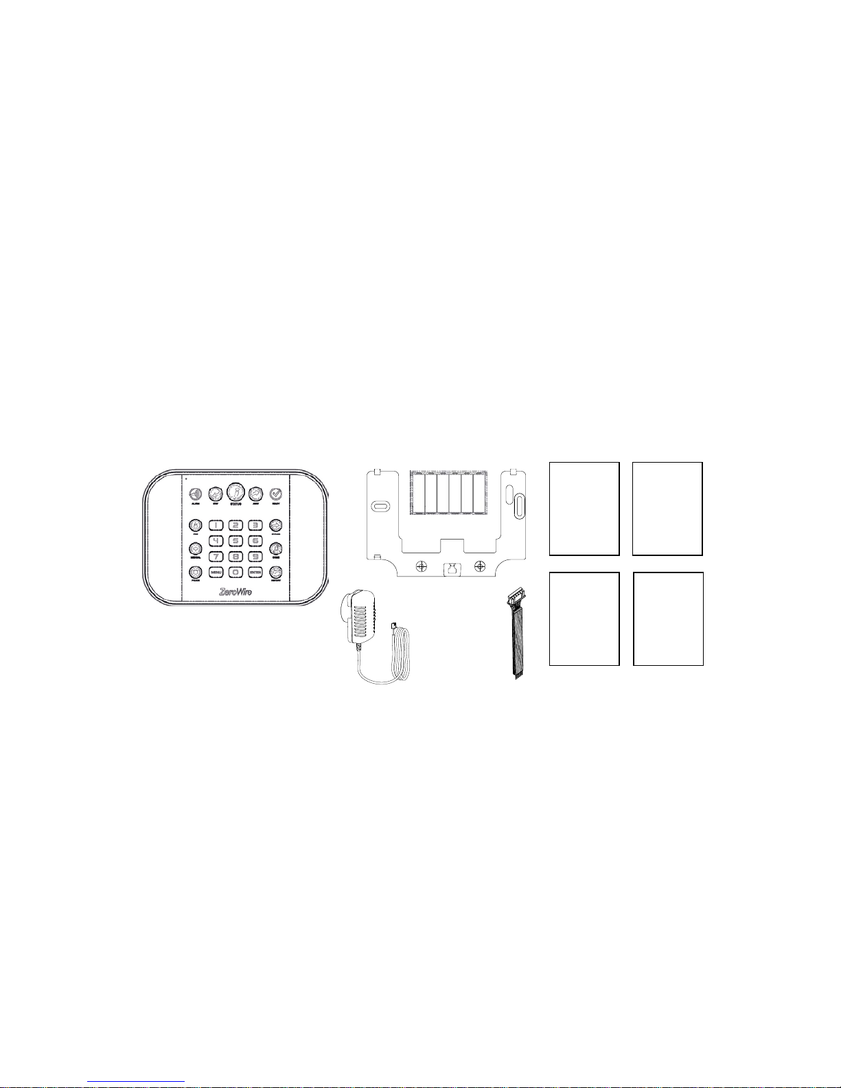
Your new security system
Check that everything is complete before beginning your installation. I f anyt hing
is missing please contact the customer service.
• ZeroWire (model ZW-6404): ZeroWire Home automation and security system
• Wall Bracket
• 9 VDC Power Pack
• Backup Battery Pack
• Input/Output Lead
• Quick Installation Guide
• Installation Manual (this document)
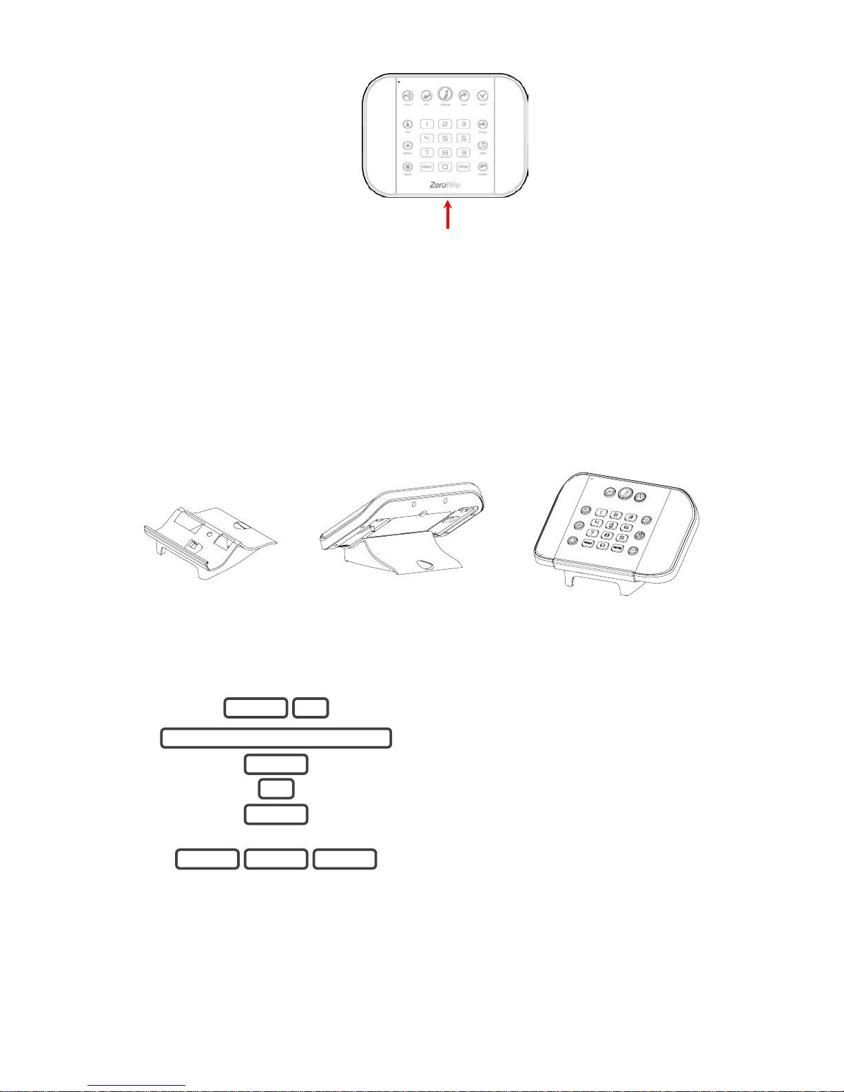
Optional parts
• ZW-DS01 Desk Stand
• ZW-MB01 Incline Bracket
• ZW-7000 3G Cellular Radio
• ZW-ANT3M Extension Antenna
Installation
Manual
(this
document)
(online)
User
Manual
(online)
Reference
Guide
(online)
Quick
Installation
Guide
Page 13
ZeroWire Installation Manual 11
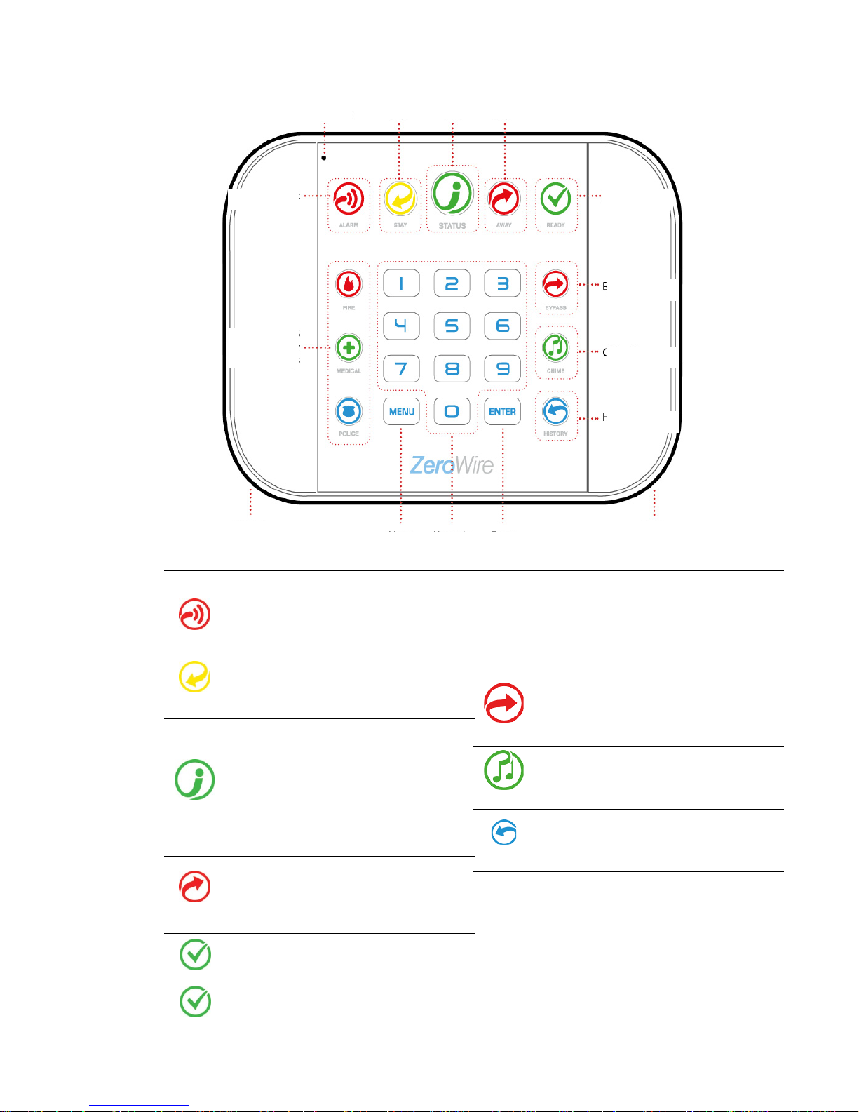
Front of ZeroWire
Key
Colour
Description
ALARM
Red
System is in alarm. Enter your PIN
code then ENTER to turn off the
alarm. Press STATUS key for more
info.
STAY
Not lit
System is disarmed if Away is also
not lit. Press the STAY key to arm
in Stay mode.
Yellow
System is armed in the “STAY”
mode.
STATUS
Green
System is normal.
Yellow
Non-urgent system conditions
present. Press the STATUS key to
hear system conditions.
Red
(steady)
Urgent system conditions present.
Touch the STATUS key to hear system
messages. If you are unable to fix the issue,
contact your service provider for help.
AWAY
Not lit
System is disarmed if Stay is also not
lit. Press the AWAY key to arm in
Away mode.
Red
System is armed in the “AWAY”
mode.
READY
Not lit
System cannot be armed, press
STATUS key for more info.
Green
(steady)
All zones are ready and the system can
be armed in Away or Stay mode.
Key
Colour
Description
READY
Green
(flashing)
Zones are currently unsealed but
system is force-armable. If these zones
are not sealed by the end of the exit
time the system will go into alarm
(unless set up for automatic bypass).
BYPASS
Press the BYPASS key if you wish to isolate
(ignore) a zone. Bypassed zones will not be
active when you arm the system in Stay or
Away modes.
CHIME
Press the CHIME key to select which zones
will make a doorbell sound on the
ZeroWire
when they are tripped.
HISTORY
Press the HISTORY key to listen for alarm and
event history.
FIRE
MEDICAL
POLICE
Feature must be enabled by your secur ity
provider. Check what response will be
provided. Hold down the key to send a
message to a
central monitoring centre. Enter
your PIN code then ENTER to turn off a SO S
alarm.
Microphone
Stay Arm Key
Status Key
Away Arm Key
Ready Light
Bypass Key
Chime Key
History Key
Siren
Enter Key
Numeric
Keys
Menu
Key
Speaker
Alarm Light
SOS
Emergency
Keys
Page 14
14
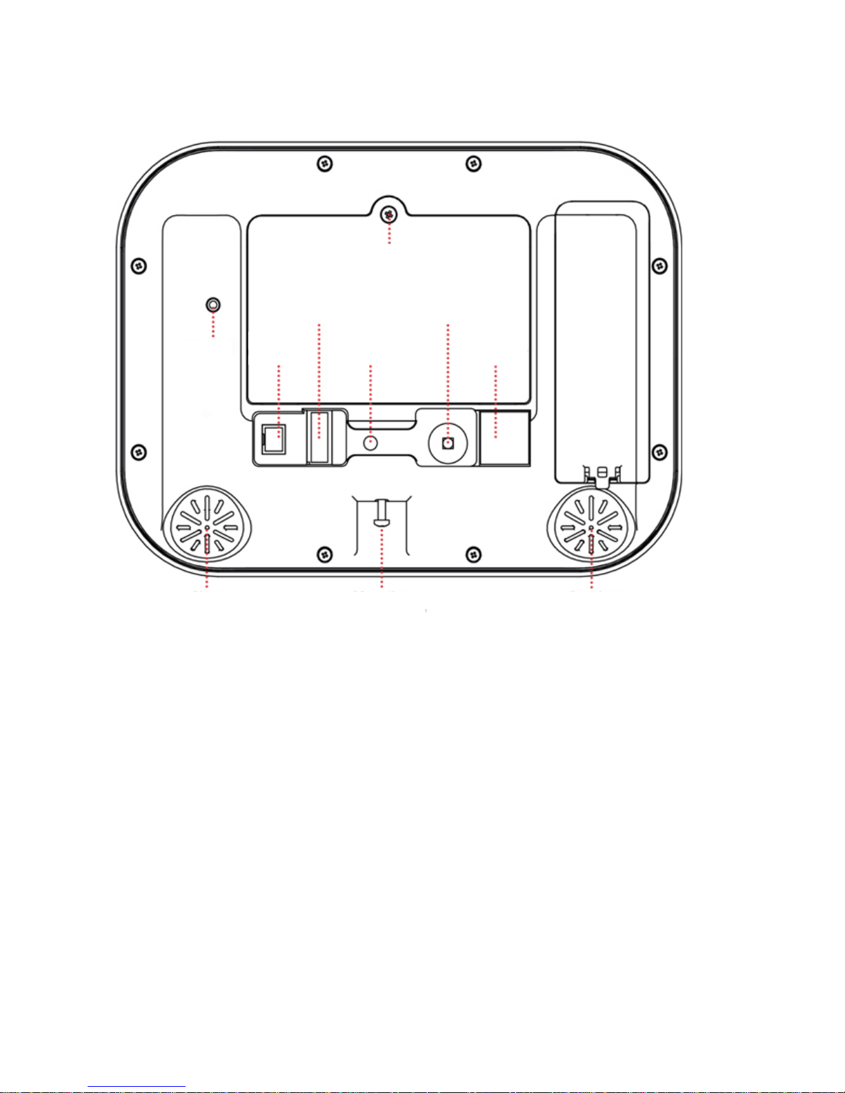
Back of ZeroWire
Connections for the cellular radio module are located under the cover on the right.
Panel
Tamper
Battery Cover
Screw
Input/Output
Connector
External
Antenna
Connector
Ethernet
Connector
Cellular
Radio
Cover
Reset
Button
Power
Connector
Siren
Mounting Bracket
Screw
Speaker
Page 15

ZeroWire Installation Manual 15
Glossary
Action
An action allows the ZeroWire to perform automation functions. These can monitor
the status up to 4 input conditions called Action Events, change state (Action State),
and perform a function (Action Result) such as arming a range of areas.
Action Group
An action group is one or more actions that can be accessed by a device or user.
They are assigned to a user or device via permissions.
Area
Zones are grouped into area
s which can be secured independently from each other.
This allows you to split your security system in to smaller components that can be
separately managed. For example your system can be divided into an upstairs area
and downstairs area.
Area
Group
An area group is one or more areas that can be accessed by a device or user. They
are assigned to a user or device via permissions.
Arm
To turn your security system On.
Arm
-Disarm
Automatically arm and disarm areas by a specific user according to a specified
schedule. The areas armed and disarmed will be the ones that the user has access
to via their permissions.
Away Mode
To turn your security system on when you are leaving the premises.
Bypass
Zones can be temporarily disabled so they will not be monitored by the securit y
system. For example, an interior door is l eft open, bypass it to temporarily ignor e i t
and allow arming of the security system. Bypassed zones are not capable of
activating an alarm. Zones wil
l return to normal operation when the system is armed
then disarmed. This prevents unintentional permanent disabling of a zone.
Central Station
A company to which alarm signals are se nt during an alarm report. Also known as
Central Monitoring Station (CMS).
Channel
A channel is a communication path for events to be sent from the ZeroWire panel to
a selected destination. Channels can be set to UltraSync or Email.
A channel has an associated event list which contains the events it is allowed t o
forward on.
Channel Group
A channel group is one or more destinatio ns for event messages to be sent to.
When a message is sent to a channel group, it is sent to all the channels that it
contains. It forms the basis of multi -path reporting in ZeroWire.
Chime Group
All the zones that will activate chime, when in chime mode.
Chime Mode
An operational mode that will emit a ding-dong sound at the keypad when specific
zones are activated.
Communicator
The communicator is responsible for notifying a control room or third party that an
alarm event has occurred so an appropriate response can be made.
It sends event messages to the specifi ed destination including details such as where
the event originated from and the t ype of event. The receiver will then log the time
and date when it receives the event. For example, Alarm from Zone 2 in Area 1 at
3:00am on 5/5/2014 from Account 1234.
ZeroWire has multiple communicator options including Ethernet IP inter face, email,
and 3G (with optional cellular radio m odule).
Disarm
To turn your security system Off.
Duress Code
A predetermined user PIN code that will arm / disarm the security system whilst
sending a special code to the central monitoring station indicating the user is
entering / leaving the premises under duress. Only applicable on monitored
systems.
Page 16

16
Entry Delay
The time allowed to disarm your security system after the first detection device has
been activated.
Event
Events are messages that are sent by the ZeroWire due to system or area
conditions. These include areas in alarm, opening and closing, zone bypass, low
battery, tamper, communication trouble, and power issues.
Event List
Event lists contain events that a channel is allowed to send to the specified
destination. If a channel receives an event that is not in the associated event list,
then the channel will ignore the event.
Exit Delay
The time allowed to exit the premises after the security system is armed.
Forced Arming
An option that permits arming even when there are unsealed pre-selected zones.
Generally assigned to zones that cover the ZeroWire (e.g.; motion zones, front door
reed switches), allowing the user to arm the security system without the need to wait
for those zones to be sealed. A security system that is ready to be “force armed” will
flash the ready light.
Master Code
A PIN code that is used by a user to arm or disarm the security system. Its main
feature is the ability to create, alter and delete user PIN codes. Can also be used as
a function code for all features.
Menus
ZeroWire has a large range of features sorted into various menus such as Users,
System, and Zones. Each menu item can be seen when using the ZeroWire Web
Server or the UltraSync + app.
Menus are used to restrict what is displayed by a device and what features a user
has access to.
Monitored
A security system that is configured to send all alarm signals to a central monitoring
station.
Output
Outputs on the ZeroWire panel can be connected to a siren and strobe when an
alarm condition occurs on the system.
Perimeter
Typically this refers to zones located around the boundary of the protected area
such as zones on doors and windows, and exc l udes interior motion zones.
Permission
A permission includes a list of features a user or device is allowed to access. This
includes programming menus, areas, r eporting channels, actions, reporti ng options,
access control options, special opt ions, and special timers.
Profile
Each user can have up to four (4) permis sion profiles. Each profile contains a set of
permissions and a corresponding sc hedule. This allows advanced user
programming and provides specifi c access to different features of the secur ity
system during specific dates/time.
With advanced programming, profiles can be enabled/disabled in response to
system conditions.
Quick Arm
An option that allows you to turn on (arm) the security system by touching the
[AWAY] key.
Scene
Each scene can trigger up to 16 actions to c reate an automation event. This can
save users time by automatically running multiple actions. A scene can be triggered
manually, through a schedule, or via a system event.
Schedule
A schedule is a list of up to 16 sets of days and times. Typically these are used to
provide access to users only within the specified sets of days and times. Outside of
the schedule a user will not have access to t he system.
Schedules are used to automatically arm and disarm specified areas using the ArmDisarm feature.
Scenes can perform a set of actions according to a specified schedule.
Schedules themselves can be enabl ed and disabled through actions. T his powerful
feature allows you to provide conditi onal access to various users and devices based
on system conditions.
Page 17

ZeroWire Installation Manual 17
Sealed
A zone in a normal state is “sealed”. The security system monitors each zone for
changes in state from sealed to unseal ed and can respond with certain actions such
as sounding the siren.
For example, a reed switch on a front door may change from a sealed state to an
unsealed state when the door opens.
Service Provider
The installation / maintenance com pany servicing your security system.
Stay Mode
To turn your security system on when you are staying in the premises, this will
automatically bypass pre-programmed zones and arm others. Often used to arm
only the perimeter while allowing mov em ent inside the premises.
Tamper
A physical switch on a device that detec ts unauthorised access to the unit. F or
example opening the case of a zone or taking a keypad off the wall can trigger a
tamper alarm. This can provide early warning of someone attempting to undermine
the security of your system. Some devices use an optical zone to detect removal
from a surface.
Token
Each token is a pre-recorded word or phrase that can be used to name zones,
areas, outputs, and rooms.
Each token is identified by a token numb er and a full list of tokens is in the "Voice
Library" on page 106.
UltraSync + app
Mobile app for smartphones to access your ZeroW ire. View status, control zones
and outputs, control Z-Wave devices, view cameras, program users and other
ZeroWire features. Available to download for Apple
TM
iPhoneTM and GoogleTM
Android
TM
from the respective app store. Thi s app replaces the UltraConnect app.
The UltraSync + app connects to the UltraSync cloud servers which then connects
you securely to your ZeroWire system and cameras.
UltraSync Servers
A secure cloud service with full redundancy t o r oute encrypted alarm messages
from your ZeroWire to a Central Monitoring Station. It also provides secure
connections between the UltraSync + app, ZeroWire, and cameras. No
programming, email addresses, us er names, or PIN codes are stored on these
servers for greater security.
Unsealed
A zone in an abnormal state is “unsealed”. The security system monitors each zone
for changes in state from sealed to uns ealed and can respond with certain actions
such as sounding the siren.
For example, when a PIR zone detects movem ent it will change from a sealed state
to an unsealed state.
User
An authorised person who can interact with the ZeroWire security system and
perform various tasks according to t he permissions assigned to them.
Each ZeroWire user has a set of profile levels. These control what the user has
access to, a list of functions, and when the user is allowed to perform these
functions.
A user is typically a person who is assigned a PIN code and arms/disarms the
system with this code or keyfob devic e.
Users can also be automatic functions of the system. For example, ZeroWire can
automatically arm specific area
s a user has access to at a specified time. No human
interaction is required; all the permis sions of the programmed user will still be
applied and enforced.
User Code
A PIN code that is used by a user to arm or disarm the se
curity system. Also can be
used as a function code for certain features.
ZeroWire Panel
The main controller for the security syst em . It stores all programming, provides
network and other connectivity options for reporting, provides physical terminals for
connecting power, backup battery, zones, and outputs.
Page 18

18
ZeroWire Web
Server
ZeroWire has a built-
in web server which provides access to ZeroWire features via a
web browser interface or a native smar tphone app.
This allows you to performing programm ing and control of the system without
needing to be physically in front of t he ZeroWire keypad.
Zone
A detection device such as a Passive Infr aRed motion zone (PIR), reed switch,
smoke detector, panic button, etc. Zones may be physically wired to the ZeroWire
system. Also known as an input or sensor on other security panels.
Z
-Wave
ZeroWire is a Z-Wave security enabled device allowing control of Z-Wave home
automation devices. ZeroWire can act as a secure Z-Wave controller. This feature
allows remote control of Z-Wave devices from the UltraSync + app or through preprogrammed scenes.
Page 19

ZeroWire Installation Manual 19
Physical Installation
What You Need
• ZeroWire and everything inside the box
• Detectors and keyfobs you will add
• List of users and PIN codes you wish to add
• Receptacle NOT controlled by a switch to provide power
• Small Phillips head screwdriver
• Small Flathead screwdriver
• Router supporting 802.11 b or 802.11g if using local WiFi features
• Optional – desk stand
• Optional – internal or external siren and strobe
Choosing a Location
When choosing a location for your ZeroWire there are a number of appliances and areas
to avoid which could interfere with the security system.
• Choose a central location for the best reception to all wireless detectors and Z-Wave
devices
• If the ZeroWire Cellular Radio is installed select a location with sufficient signal
• Avoid TV and other electronic appliances
• Avoid microwave ovens
• Avoid wet and moist areas such as bathrooms and toilets
• Avoid cordless telephones
• Avoid computers and wireless equipment
Removing The Wall Bracket
1. Loosen the screw from a bottom of ZeroWire, this will allow the wall bracket to be
removed from the unit.
Page 20
20
Installing Cellular Radio
1. A mobile phone can provide general guidance on mobile network coverage. Look at the
signal level on a mobile phone to verify there are 4/5 to 5/5 bars of reception in the
location where you will install the ZeroWire.
1 bar
2 bars 3 bars 4 bars 5 bars
Low
OK
If the signal strength is low, find another location which has stronger signal levels.
Note that actual signal level can only be determined using the ZeroWire connected to a
specific network, which may be different than your phone.
2. If a cellular radio module is pre-installed, skip to the Check Signal Level section. If not,
remove the cover on the right.
3. Locate the 10-pin lead inside the ZeroWire and connect this to the radio module.
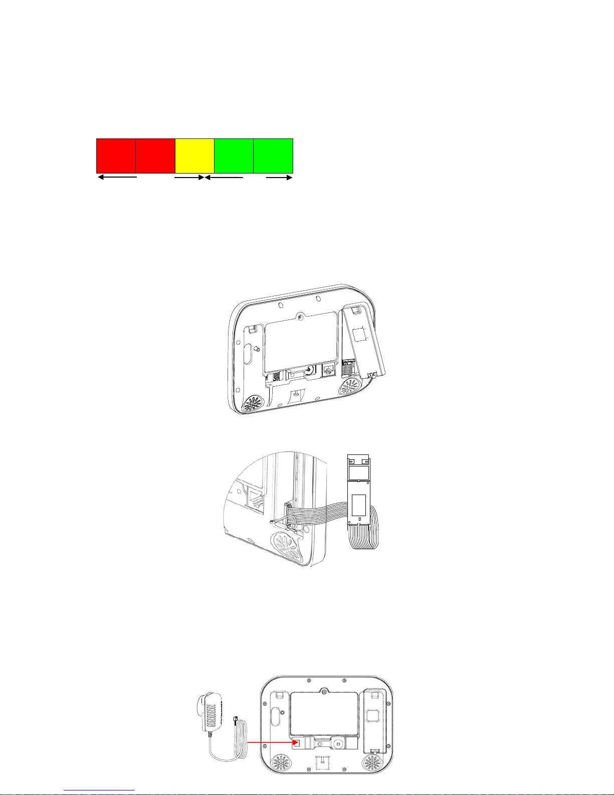
Connecting Power
1
. Connect a DC power lead from power pack to the back of the ZeroWire, it only fits
when inserted in the correct direction.
Page 21
ZeroWire Installation Manual 21
2
. Connect the power pack to power source.
Caution: • Do not connect to a receptacle controlled by a switch!
CAUTION: Wall tamper is an optional security feature that is disabled by default. When
enabled, the siren will make a very loud alarm sound when power is connected. Press
9 7 1 3 Enter to turn the siren off. If this does not work, try 1234 as User 1.
Ligh
ts should be lit on the ZeroWire when the power is turned on. If not check that the
power lead is connected securely to the rear of the ZeroWire.
Avoid using multiple power adapters and power boards.
Note:
ZeroWire should be connected to a power source at all times. The battery is a
backup power source, and the ZeroWire is designed to run on the battery pack during a
power failure only, and NOT for prolonged periods of time.
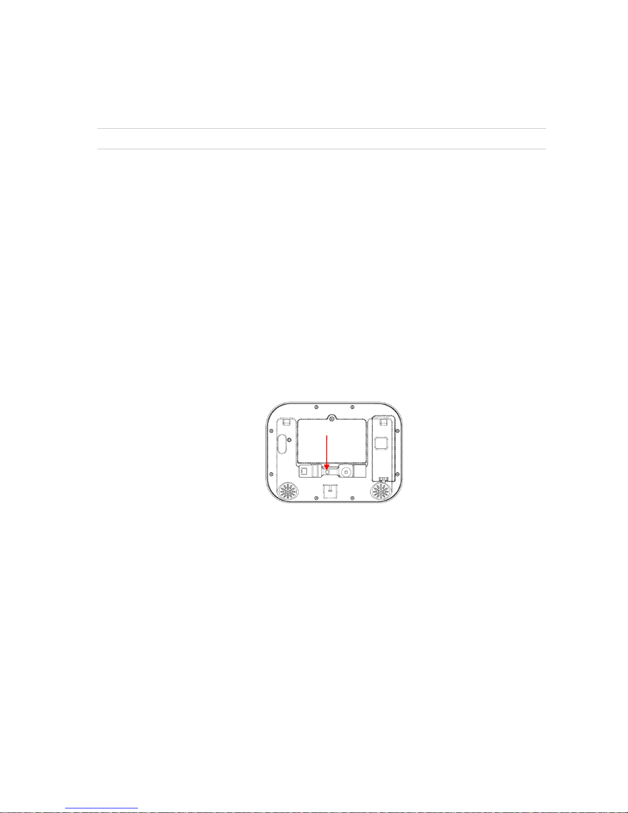
Reset Installer Account
1.
Disconnect power
2.
Use a small screwdriver to hold down the reset button
3.
Turn on power and keep holding down reset button for 3 seconds, then release the
reset button. This will reset PIN to 9713 and username “installer”, this account will not
have access to user programming.
4.
Default panel to restore all settings to factory defaults. See page 25.
Checking Signal Level
On the ZeroWire key pad:
Page 22

22
1.
Select main menu - Option 4, System Test.
2.
Enter your Installer code.
3.
Check Cellular Signal Level
Menu 5 is only available if the cellular radio has
adequate reception and the SIM card is registered on
the network
4.
Exit from the Advanced system configuration menu.
Low
OK
-121
-107
-98
-89
-76
-51
• If the reported value is -88 to -51 then the signal level is OK. In this case, skip to the
Completing Installation section.
• If the reported value is -121 to -89 then installing an external antenna is recommended.
In this case, follow steps below to install an external antenna to improve the
signal level.
Note: Remember that signal levels vary day to day and are not absolute values.
Installing The Optional External Antenna (ZW-ANT3M)
Complete this section only if signal level is between -121 to -89. Otherwise skip to
Completing Installation.
1. Disconnect power to ZeroWire
2. Disconnect the antenna cable from the radio module.
Front View Side View
3. Gently push retaining clips outwards and remove rear circuit board. This is the internal
antenna which will no longer be needed.
MENU
MENU
5
ENTER
YOUR 4 TO 8 DIGIT INSTALLER CODE
4
MENU
Page 23
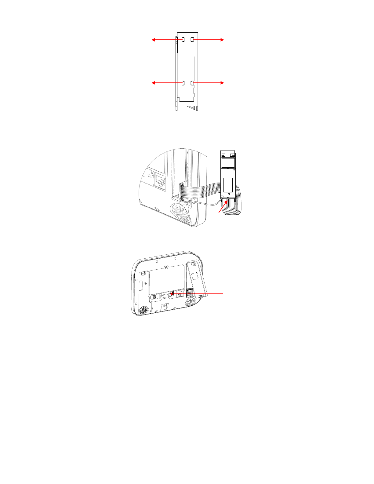
ZeroWire Installation Manual 23
Back View
4. Connect the internal antenna cable from the ZeroWire to the radio module.
5. Connect a high gain antenna to the antenna connector shown below.
6. Reconnect power and wait 1 minute for the cellular radio to connect.
7. Retest signal level in Menu 4 – 5.
8. Move the ZeroWire or the antenna to another location if the signal is still too low.
Completing Installation
1. Insert the whole radio module in to the ZeroWire taking care not to crimp any cables.
2. Replace the modem cover on the ZeroWire
External Antenna
Connector
Page 24

24
Installing The Battery
1.
Remove battery cover
with a small screwdriver.
2. Connect battery pack lead
to connector on left.
3. Replace battery cover and
screw.
Note: The battery wire cannot be under the battery or the cover will not fit properly.
Note: The battery is not designed as a long-term power source. Plugging in the battery
should be followed quickly with the plugging in of the DC power supply.
Installing ZeroWire on Wall
1. Install the bracket on a wall by using the supplied screws. Make sure the power lead
can reach the ZeroWire when plugged in to a power source.
2. Align the ZeroWire to the top clips on the wall bracket, then slide the ZeroWire in to
place so it sits flat against the wall.
3. Use a screw driver to tighten the screw you loosened previously
Page 25
ZeroWire Installation Manual 25
4. If required, the box tamper feature can be enabled from the System Menu – General
Options via the ZeroWire Web Server. This will cause an alarm to occur if the ZeroWire
is removed from the wall.
Installing ZeroWire on Desk
If you do not wish to install the product on a wall, you may use the optional ZW-DS01 table
stand to place the ZeroWire on a secure flat surface. Cables should route through the hole
in the base. Ensure the box tamper is off.
Resetting to Factory Defaults (optional)
Follow these steps to reset your ZeroWire back to factory default settings:
1.
Select main menu - Option 9.
2.
Enter your Installer code.
3.
Select resetting to the factory defaults.
4.
Confirm by pressing the BYPASS key, and then wait
10 seconds.
5.
Exit from the menu.
MENU
MENU
MENU
BYPASS
0
ENTER
YOUR 4 TO 8 DIGIT INSTALLER CODE
9
MENU
Page 26
26
Setting Up Connections
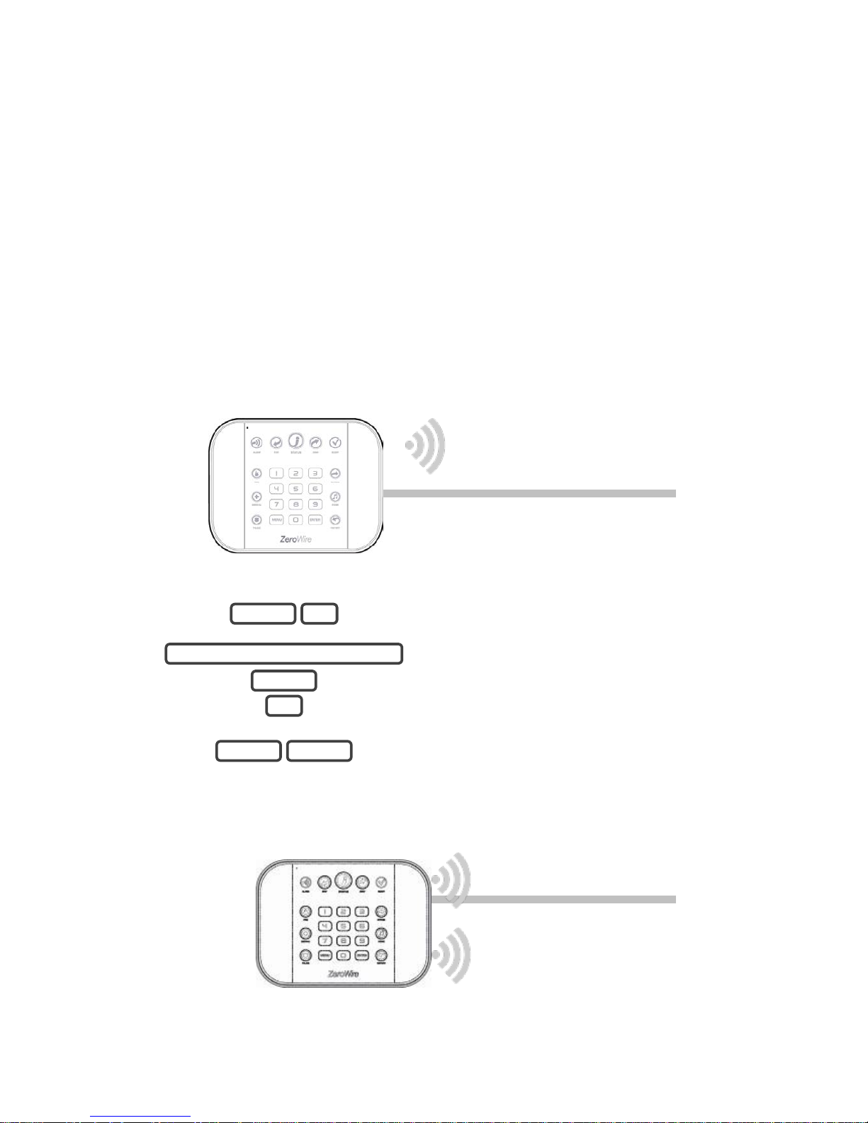
Selecting a Permanent Connection Mode
Select a method to connect your ZeroWire to a network so it can report events via
UltraSync, and allow you to configure settings using the built-in Web Server or UltraSync +
app.
1. Wireless LAN Setup – this connects the ZeroWire to a local WiFi network. You will
need to provide an internet connection and wireless router for the permanent
connection. A mobile device such as a smart phone or tablet is needed to set up this
connection.
2. Wired LAN Setup – this is the easiest to set up but requires a physical Ethernet
connection to the ZeroWire. You will need to also provide an Ethernet router and an
internet connection for reporting and remote access.
To select between Wireless LAN or Wired LAN modes:
1.
Select main menu - Option 9, Advanced system
configuration.
2.
Enter your Installer code.
3.
Toggle between Wireless LAN and Wired LAN
connection modes.
4.
Exits from Advanced system configuration menu.
3. 3G Cellular Radio Setup – this provides a plug and play connection to UltraSync
servers for secure reporting with no configuration needed in most cases. The only
requirement is good mobile phone reception.
To connect via Cellular Radio you only need to plug in the cellular radio module.
MENU
MENU
7
ENTER
YOUR 4 TO 8 DIGIT INSTALLER CODE
9
MENU
Primary Path –
wireless LAN or wired LAN
Secondary Path –
cellular 3G
Wired LAN
WiFi LAN
Page 27
ZeroWire Installation Manual 27
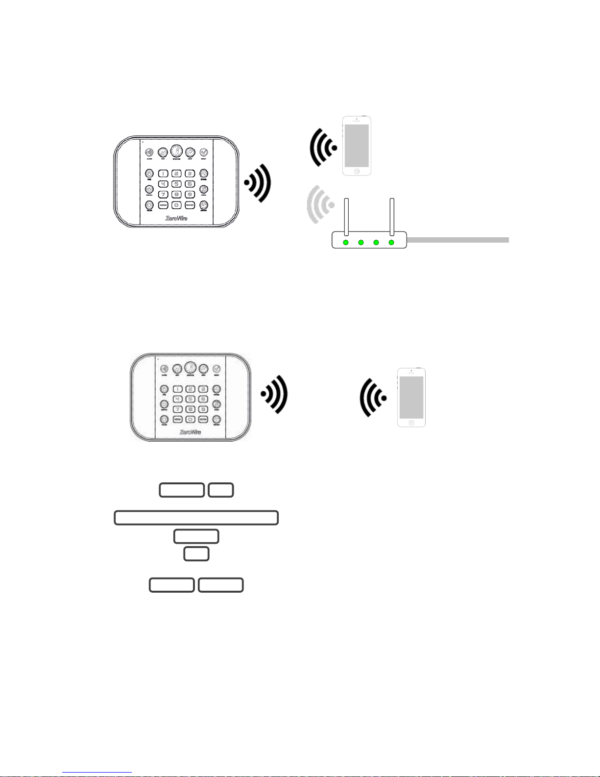
Wireless LAN Setup
Use a mobile device to connect ZeroWire to your existing WiFi network. The wireless
router must support 802.11 b or 802.11g.
1. Turn on WiFi Discovery Mode
A temporary WiFi Discovery Mode allows an initial configuration from a mobile device such
as a smart phone or tablet. This wireless connection is between the ZeroWire and the
mobile device only.
1.
Select main menu - Option 9, Advanced system
configuration.
2.
Enter your Installer code.
3.
Turn on WiFi Discovery Mode for 10 minutes.
4.
Exits from Advanced system configuration menu.
2. Enable WiFi on your mobile device.
3. On your mobile device, browse for available WiFi networks and select the
‘ZeroWire_xxxx” network to connect to it.
Note: Some devices have a “smart” feature which will check if the WiFi point has
access to the internet. If no internet is detected, the device will reconnect to another
MENU
MENU
8
ENTER
YOUR 4 TO 8 DIGIT INSTALLER CODE
9
MENU
To internet
Wireless Router
Initial address http://192.168.1.3
http://192.168.1.3
Page 28
28
WiFi point. Disable this feature or use a different device if it is unable to stay
connected.
The ZeroWire will accept only the first device that attempts to connect and there is no
WiFi password. Multiple devices cannot connect at the same time. If you need to try
from another device, turn off WiFi Discovery Mode and then back on.
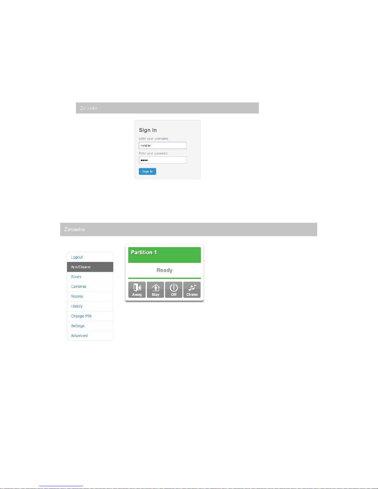
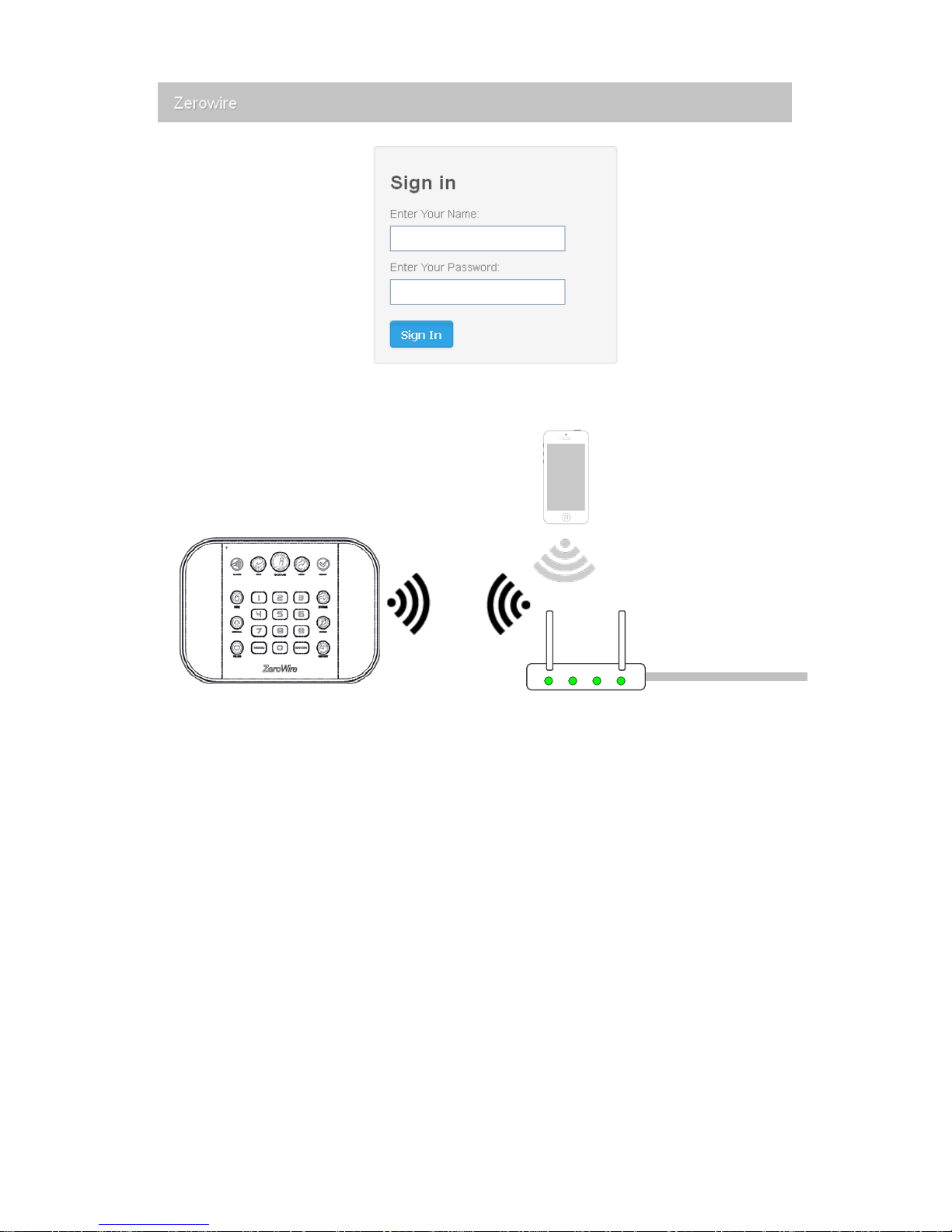
4. Open your web browser and enter http://192.168.1.3. The ZeroWire login screen
should appear:
5. Enter your username and password, by default this is “installer” and “9713”
6. Click Sign In, you should now see a screen similar to the one below:
Note: The set of menus displayed depends on the access rights of the user logged in the
system. The screen above shows default installer menus, but they can be different for a
Master User, standard user, and an installer with Master User rights. For more information,
see "Access rights and available menus" on page 37. The same applies to the UltraSync +
app.
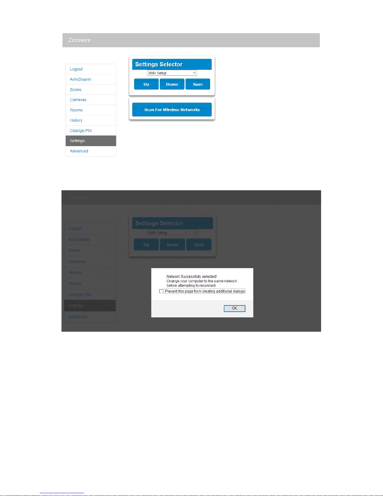
7. Click Settings.
8. Click the drop down menu and select WiFi Setup.
9. Click Scan for Wireless Networks and wait for s canning t o c om plet e:
Page 29
ZeroWire Installation Manual 29
10. Click the WiFi network name you wish ZeroWire to connect to.
11. Enter the customer’s WiFi passcode then click OK. The following message will appear:
The ZeroWire will disconnect from your device, then attempt to connect to the
customer’s WiFi network you selected. The webpage on your device will stop
responding, this is normal.
12. On your mobile device, connect to the same WiFi network you selected in step 10.
13. On the ZeroWire press Menu – 8 – [PIN] – 6 and note the IP address announced. If
you hear “IP address is not configured” then wait a further 30 s and repeat this step.
14. Open your web browser and enter http://[IP address]. The ZeroWire login screen
should appear:
Page 30
30
15. Your ZeroWire is now successfully connected to your WiFi network:
Troubleshooting
If the connection does not work or you cannot get an IP address, close the web browser
on your phone, and restart your wireless router, and start again from step 1.
Sometimes settings on your wireless router may prevent a connection. Check:
• WiFi router allows b and g connections. Some newer routers will have these off at
factory default. Some 802.11n access points may not accept 802.11g connections.
• it is within range and has good signal, otherwise a WiFi range extender may help
• the wireless router has DHCP enabled
• does not have firewall or security rules that prevent additional connections
• IP addresses are available, for example connect a new device to it and verify it has an
internet connection
To internet
Wireless Router
Press Menu, 8, PIN, 6
for permanent address
Page 31

ZeroWire Installation Manual 31
Checking WiFi Connection to UltraSync
1. Log in to the ZeroWire. Web Server from your mobile device using the IP address
announced
2. Click Settings
3. Select Connection Status in the drop down menu
4. Check that
a. LAN Status should display “Connected”,
b. LAN Media should display “WiFi”,
c. UltraSync Status should display “Connected”,
d. UltraSync Media should display “LAN”.
If it does not:
1. Check cable connection.
2. Check router settings.
Page 32

32
Wired LAN Setup
1. Connect power to your ZeroWire.
2. If this ZeroWire was previously connected via WiFi, switch the connection to Wired
LAN:
1.
Select main menu - Option 9, Advanced system
configuration.
2.
Enter your Installer code.
3.
Toggle between Wireless LAN and Wired LAN
connection modes.
4.
Exits from Advanced system configuration menu.
3. Connect an Ethernet cable to the rear of the ZeroWire and wait 10 sec for the local
router to assign the ZeroWire an IP address.
4. On the ZeroWire press Menu, 8, [PIN], 6 and note the IP address announced. If you
hear “IP address is not configured” then wait a further 30s and repeat this step.
5. Open your web browser.
6. Enter http://[IP address]. The ZeroWire login screen should appear:
7. Enter your username and password, by default this is "installer" and 9713.
8. You should now see a screen similar to the one below.
MENU
MENU
7
ENTER
YOUR 4 TO 8 DIGIT INSTALLER CODE
9
MENU
To internet
Router
Page 33

ZeroWire Installation Manual 33
Note: The set of accessible menus depends on the access rights of the user logged in the
system. The screen above shows default installer menus, but they can be different for a
Master User, standard user, and an installer with Master User rights. For more information,
see "Access rights and available menus" on page 37. The same applies to a connection
via the UltraSync + app.
9. Your ZeroWire is now successfully connected to your Wired LAN network.
Click Settings or Advanced to program your ZeroWire.
Check LAN Connection to UltraSync
1. Log in to the ZeroWire Web Server from your mobile device using the IP address
announced.
2. Click Settings.
3. Select Connection Status in the drop down menu.
4. Check that:
a. LAN Status should display “Connected”,
b. LAN Media should display “Ethernet”,
c. UltraSync Status should display “Connected”,
d. UltraSync Media should display “LAN”.
Page 34

34
If it does not:
1. Check cable connection.
2. Check router settings.
3G Cellular Radio Setup
An optional 3G cellular radio modem provides a backup reporting path to the central
monitoring station over a cellular network if the Ethernet/WiFi connection is not working.
Your cellular radio module should be pre-configured and function once plugged in to the
ZeroWire. If not, please refer the manual that comes with the cellular radio for instructions
on how to install it.
3G cellular network
Mobile Phone Tower
To internet
Page 35

ZeroWire Installation Manual 35
In order to check the 3G radio signal strength:
1. Turn on WiFi Discovery Mode – this provides direct access to the ZeroWire from a
mobile device such as a smart phone, tablet, or laptop:
1.
Select main menu - Option 9, Advanced system
configuration.
2.
Enter your Installer code.
3.
Turn on WiFi Discovery Mode for 10 minutes.
4.
Exits from Advanced system configuration menu.
2. Enable WiFi on your mobile device.
3. On your mobile device, browse for available WiFi networks and select the
‘ZeroWire_xxxx” network to connect to it. Only a single user can connect at any time
and there is no WiFi password. Once connected, the ZeroWire will be assigned a fixed
IP address of 192.168.1.3.
4. Open your web browser and enter http://192.168.1.3. The ZeroWire login screen
should appear.
5. Enter your username and password, by default this is “installer” and “9713”
6. Click Sign In, you should now see a screen similar to the one below:
Note: The set of accessible menus depends on the access rights of the user logged in the
system. The screen above shows default installer menus, but they can be different for a
Master User, standard user, and an installer with Master User rights. For more information,
see "Access rights and available menus" on page 37. The same applies to a connection
via the UltraSync + app.
7. Click Settings.
8. Select Connection Status in the drop down menu.
MENU
MENU
8
ENTER
YOUR 4 TO 8 DIGIT INSTALLER CODE
9
MENU
Page 36

36
9. Check that:
• UltraSync Status should display “Connected”,
• Cell Service should display “Valid service”,
• Signal Strength should display a value between -91 to -51.
If it does not:
• Check cellular connection:
1. Look at cell state, it should display “Connected”.
2. Wait until cell state displays “Connected”, click Reload to refresh the status.
3. Check signal level in Menu 4, 5 – signal level should be between -91 to -51.
4. Contact Tech Support for assistance.
• Check radio module is correctly installed.
• Check radio antenna is correctly installed or move the antenna to a higher location.
• Check cable connection of Ethernet cable.
• Check router settings.
Page 37

ZeroWire Installation Manual 37
10. If you need to make changes, open the ZeroWire Web Server and go to Advanced –
Communicator – Radio Configuration:
Only change these settings as instructed by your supplier or telecommunications provider.
Access rights and available menus
The set of accessible menus depends on the access rights of the user logged in the
system.
Main Menu – Installer Code
The screen above shows the ZeroWire’s menu when accessed via installer code when the
installer code is NOT set with master user authorities. Particularly, no User sett ings are
available to the installer.
Note: The Installer type can only be set via the DLX900 software.
Page 38

38
Main Menu – Installer Code with Master Authority
The screen above shows the ZeroWire’s complete menu when accessed via the default
installer code with master access. This is a default view for the first installer login.
Note: The Master Installer type can only be set via the DLX900 software.
Main Menu – User with Master Code
Advanced installer menus will be hidden when accessed by a user with a master code.
This is a default view for the first "User 1" login.
Main Menu – Standard User Code
When accessed by standard users, all menus for changing system settings and settings
for other users will be hidden.
Page 39

ZeroWire Installation Manual 39
Enabling Access to UltraSync + app
For security, the UltraSync + app is disabled by default. Follow these steps to enable it:
1.
Select main menu - Option 9, Advanced system
configuration
2.
Enter your Installer code
3.
Change Web Access Passcode
4.
Enter a new Web Access Passcode
5.
( ( CODE FLASHES ON KEYPAD ) )
Passcode will flash on keypad for confirmation
6.
Exits from Advanced system configuration menu
Alternatively, you may use the Web Server:
1. Log in to the ZeroWire Web Server from your mobile device using the installer account.
2. Click Settings.
3. Click Network.
4. Enter a Web Access Passcode:
MENU
MENU
ENTER
8 DIGIT CODE
9
ENTER
YOUR 4 TO 8 DIGIT INSTALLER CODE
9
MENU
Page 40

40
3. Enter a first name:
Installing UltraSync + app
UltraSync is an app that allows you to control your ZeroWire from an Apple® iPhone/iPad,
or Google Android device. First set up the ZeroWire Web Server then download this app.
Carrier charges may apply and an Apple iTunes or Google account is required.
1. On your smartphone go to the Apple® App StoreTM or Google PlayTM store.
2. Search for UltraSync.
3. Install the app.
4. Click the Smart Home icon on your device to launch it.
5. Click + on the top right to add a new site, or the (i) icon to edit an existing site.
6. Enter the details of your security system.
The serial number is printed on the back of the ZeroWire unit. Alternatively login to
ZeroWire Web Server and go to Settings – Details to view it.
The default Web Access Passcode of 00000000 disables remote access. To change it,
login to ZeroWire Web Server and go to Settings - Network.
The default username and PIN code is "installer" 9713 (for an installer) and “User 1”
1234 (for a user). Please note that there is a space between "User" and "1". You may
also use any other valid user account. Only menus a user has access to will be
displayed.
7. Click Done button to save the details, then Sites to go back.
8. Click the name of the Site, the app will now connect you to ZeroWire.
Page 41

ZeroWire Installation Manual 41
Troubleshooting
• Check the serial number, web access passcode, user name and PIN codes match
those in the ZeroWire.
• Web Access Passcode must not be 00000000.
• User Name must be entered with a space between the first and last name and with
correct capitalization.
• If connected by Wired LAN, check the cable is plugged in and that the connection is
working.
• If connected by WiFi LAN, check the connection is working.
• If switching between WiFi and Ethernet modes, logout of webpage, keypad
programming, and app to end current session. This allows the panel to reconnect on
the new mode.
• Check Settings – Network – Enable UltraSync is ticked.
• Check that your mobile device has access to the internet (e.g. open a web browser).
• Try disabling WiFi on your device once the ZeroWire is configured, and using the
3G/4G data connection of your device with the UltraSync + app.
• Check the UltraSync servers are correct under Advanced – UltraSync:
a. Ethernet Server 1 - zw1.ultraconnect.com:443
b. Ethernet Server 2 - zw1.zerowire.com:443
c. Wir eless Server 1 - zw1w.ultraconnect.com:8081
d. Wireless Server 2 - zw1w.zerowire.com:8081
• Power cycle connected equipment including ZeroWire and customer supplied router(s).
Using the UltraSync + app
Page 42

42
The first screen that will appear once you connect is the Overview screen. This will display
the status of your system and allows you to arm or disarm areas by touching Arm Away,
Arm Stay, or Disarm. It also allows you to activate programmed automation scenes.
The menu bar is located along the bottom of the app. Touch the Zones icon (last icon with
a dot and wireless signals) to view zone status.
• Touch Bypass to ignore a zone or touch it again to restore it to normal operation.
• Touch Chime to add or remove a zone from the Chime feature.
• Touch Notify to receive push notifications when there is activity from that zone.
Page 43

ZeroWire Installation Manual 43
Touch the Camera icon to view cameras connected to your system.
• Live snapshots from each camera will be shown. Touch the snapshot to open the
live stream in full screen. Rotate your device to make the image bigger. Touch the
screen then Back to return to the Camera screen.
• Touch the Play button under each camera to view the last recorded clip by that
camera. Touch the Share button to save or forward the clip.
• Touch the Record button to request that camera record a short clip which can be
retrieved at a later date.
Video clips can also be accessed from the History screen. Touch Menu , HISTORY,
then change Selected Events to Video. Touch “Press to Play Video” to retrieve the clip
from the camera. Once downloaded, you can save or forward the clip.
Page 44

44
This History screen displays the event log of the ZeroWire, recording important events and
allowing authorized users the ability to audit the system. Changing the Selected Events to
Alarms will display the filtered Mandatory Event Log. Events followed with an * are for
events not intending to be reported to a control room.
If you have Z-Wave devices installed, touch the Light or Lock icon to view and control
them.
Master users will have access to the full Users menu for creating and managing users.
Touch Menu , USERS. After making any changes remember to click Save. To apply
custom permission to a user, change User Type to Custom to show additional options.
Page 45

ZeroWire Installation Manual 45
When you login with the installer account you will have access to the ADVANCED menus
for setting up and programming the ZeroWire. Refer to the ZeroWire Reference Guide for
additional help on the Advanced screen.
Recommended Items To Change
• Installer Code. This is the master key to most features. Always change this to prevent
accidental modifications by end-users and an unauthorized access to the security
system.
• User 1 PIN code is 1234 at default. Always change this to prevent unauthorized access
to the security system.
• User 1 username is “User 1” at default, with a space between "User" and "1". This is
required to provide end-user access to the ZeroWire Web Server and UltraSync + app.
Make it blank to prevent end-user access.
Page 46

46
• Web Access Passcode and Download Access Code. These provide access to the
ZeroWire Web Server, UltraSync + app, and upload/download from the DLX900
management software.
• Enable remote access for UltraSync + app by changing Web Access Code. The default
Web Access Passcode of 00000000 prevents remote access. To change it, login to
ZeroWire Web Server and go to Settings - Network.
Page 47

ZeroWire Installation Manual 47
• Enable remote access for DLX900 by changing Download Access Code. The default
Download Access Passcode of 00000000 prevents remote access. To change it, login
to ZeroWire Web Server and go to Settings - Network.
Page 48

48
Note: DLX900 will attempt to connect using the default installer/9713 account. To
disable DLX900 access change the installer PIN code and set the Download Access
Code to 00000000.
• Installer Service Phone Number – This is announced to the end-user when certain
status conditions occur. For example when there is a low battery, the Status button will
turn red. When the Status button is pressed it will announce the condition, then this
phone number. Add your phone number under Advanced\ \System\Service and Test
Options.
Troubleshooting
Problem
Solution
Cannot get IP address
If you are unable to get an IP address then your wireless/router
may not be configured for automatic DHCP or certain se curit y
settings may be enabled. Check your router settings and t ry
again.
Cannot see local WiFi access
point from smartphone
Ensure your WiFi access point is able to accept 802.11b or
802.11g. Some 802.11n access points may not accept 802.11g
connections.
Page 49

ZeroWire Installation Manual 49
Installation Using a Keypad
Basic Installation
It is possible to quickly install and test zones using only the ZeroWire keypad, the voice
guide will walk you through each option that requires programming.
Additional zone settings can be accessed via the ZeroWire Web Server, UltraSync + app,
or DLX900.
The keypad will be locked in screensaver mode when unused for a set time. A valid PIN is
required to unlock the ZeroWire and access the ZeroWire system. Users can set PIN
codes between 4 and 8 digits in length.
Please note that the PIN code should be entered twice to be validated.
When an incorrect PIN is entered 3 times the keypad is locked for 60 seconds and the
voice will say “Access denied”. During this time the keypad will not be operational and PIN
codes cannot be entered.
After the 60 seconds expires, if the first PIN attempt is incorrect, the 60 second time will
start again. If the PIN code is valid, then the counter will reset and further 3 attempts can
be accepted.
Unpacking Detectors
These instructions are for general information only. Please refer to the manual included
with each detector for further details.
1. Remove the detector from packaging.
2. Remove a battery cover of the detector.
3. Install batteries taking care to insert them correctly. Batteries inserted with reverse
polarity may damage the detector.
Installation Suggestions
• Wireless detectors feature low power transmission to maximize battery life. This means
you should place the ZeroWire in a central location and install detectors as close to the
ZeroWire as possible.
• Signals from each detector will reduce in strength as they pass through different
building materials with brick and concrete absorbing more of the signal.
• Keep detectors away from household appliances and metal surfaces (e.g. refrigerator,
TV, washing machine, garage door). Metal surfaces will reflect the signal away.
• If you have a double-storey property, it is suggested the ZeroWire unit be installed on
the highest level for the best signal strength.
• ZeroWire installed below ground level (e.g. basement) may have reduced range.
• Motion/Passive Infra-Red (PIR) detectors should be installed to look over the area you
want to protect. The path of an intruder should walk across the front of the PIR. A PIR
Page 50

50
is less sensitive to an intruder walking directly towards it. Avoid pointing the PIR at
windows or heat sources as these may cause the PIR to operate incorrectly.
• Reed switches should be installed across doors/windows where two surfaces open and
close. Place the detector on the frame and the magnet on the door/window. Take care
to close the door/window and note any gap between the magnet and the detector. If the
gap is large the detector will always be in an open state and prevent you from
arming/disarming the system. A plastic spacer can be used to ensure the reed switch
seals correctly.
Learning Detectors into ZeroWire
Example: Add a PIR motion detector to ZeroWire and assign it as zone 1.
1.
Select Zone Configuration.
2.
Enter your Installer code.
3.
Select 1 to add detector.
4.
Activate the detector learn-in sequence (see specific
wireless detector manual for instructions).
ZeroWire will announce that the detector or keyfob is
detected.
5.
Assign the detector as zone number 1, or just press
Enter to automatically assign a number.
Press 1-6 for the zone type.
6.
Exit from the menu.
Zones Guide
A zone (sometime referred to as a detector, sensor, or input) on the ZeroWire is a single
physical hardwired connection or a wireless connection. They can be configur ed as one of
many zone types that greatly increase the functionality of the ZeroWire system.
Additionally zones on the ZeroWire can be used as logic inputs within actions.
Zone Number
The ZeroWire can support a total of 64 zones. Each zone is identified by a unique zone
number, which cannot be altered, and remains as the key reference for each zone.
MENU
MENU
MENU
ENTER
1
ENTER
1
PRESS DEVICE BUTTON
1
ENTER
YOUR 4 TO 8 DIGIT INSTALLER CODE
5
MENU
Page 51

ZeroWire Installation Manual 51
Zone Type
The zone type can be changed using the ZeroWire keypad to one of the following defaults.
If you require further customization please use the ZeroWire Web Server, UltraSync + app,
or DLX900 to access more advanced settings.
Option
Voice Zone Type Zone Options
1
Delay Zone Type 3 Entry Exit Delay 1 1 Bypass
2
Delay Zone Type with Bypass in Stay Mode 3 Entry Exit Delay 1 2 Bypass Stay
3
No Delay Zone Type 6 Instant 1 Bypass
4
No Delay Zone Type with Bypass in Stay Mode 6 Instant 2 Bypass Stay
5
24 Hour Zone Type 2 24 Hour Audible 6 Panic
6
24 Hour Silent Zone Type 7 24 Hour Silent 7 Silent Panic
Smoke Zones
Smoke Zone 8 Fire Alarm 5 Fire
Configuring Zone Names
All zones can be named using library words on page 106. This makes it easier to identify
the correct detector in the event of a condition. You may enter up to eight words to achieve
your desired description.
Example: Configure zone 1 name as “Dining Room Zone”
1.
Select main menu - Option 6, Basic system
configuration.
2.
Enter your Installer code.
3.
Select zone name recording.
4.
Select zone 1.
5.
Select word “Dining” from the word library.
Select word “Room” from the word library.
Select word “Zone” from the word library.
6.
Exit from the menu.
If you do not require all eight words, just press MENU as in step 6 after you have entered
the last word number.
MENU
MENU
MENU
ENTER
2 2 1
ENTER
8 1 1
ENTER
3 5 ENTER
1 4 ENTER
YOUR 4 TO 8 DIGIT INSTALLER CODE
6
MENU
Page 52

52
Recording Zone Names (optional)
You can also record the names of the first 64 zones using your voice.
Example: Record user name for zone 1
1.
Select main menu - Option 6, Basic system
configuration.
2.
Enter your Installer code.
3.
Select zone name recording.
4.
Select zone 1.
5.
Activate recording mode.
6.
Record voice, maximum 2 seconds.
7.
Stop recording mode.
8.
Exit from the menu.
Testing Zone Signal Level
Check the signal level of each zone once installed.
1.
Select Main Menu - Option 4 – System Test
2.
Enter your Installer code.
3.
Select zone walk test
6.
Trip each zone and listen to the voice feedback on the
panel.
8.
Exit from the menu.
If signal is low, then move zone to another location. Alternatively move your ZeroWire to a
more central location.
MENU
MENU
MENU
TRIP DETECTOR
4
ENTER
YOUR 4 TO 8 DIGIT INSTALLER CODE
4
MENU
MENU
MENU
MENU
RELEASE HISTORY
( ( SPEAK NAME ) )
HOLD DOWN HISTORY KEY
ENTER
1 4 ENTER
YOUR 4 TO 8 DIGIT INSTALLER CODE
6
MENU
Page 53

ZeroWire Installation Manual 53
Removing a Zone
Example: Remove zone 8
1.
Select Zone Configuration.
2.
Enter your Installer code.
3.
Select 2 to remove a detector (zone) or keyfob.
4.
Select 1 to remove a detector (zone).
5.
Select the zone number that needs to be removed.
6.
Exit from Advanced system configuration.
Adding a User/Keyfob
ZeroWire allows you to add up to 40 users. Each user is assigned a PIN code and a user
number between 1 and 1000. This allows them to interact with the system. Advanced user
settings are only accessible via the ZeroWire Web Server, UltraSync + app, or DLX900.
Note: PIN Codes must be unique across the system; no two users can share the same
PIN code.
PIN codes must be 4 to 8 digits in length.
User name must be assigned to give that user access to the UtraSync + app or ZeroWire
Web Server.
The default installer account is User 256 with the user name "installer" and PIN code 9713,
with Master Engineer user type. These details are used to login to the ZeroWire Web
Server web pages and UltraSync + app.
The default master account is “User 1” and PIN 1234, with a space between "User" and
"1".
Example: Add a new user to ZeroWire and assign them a PIN code 2580. We will add this
as user 4.
1.
Select User Configuration menu.
2.
Note: installer account does NOT have access to u sers,
must use a master code.
3.
Select 1 to configure user PIN.
4.
Select user 4.
5.
Set user 4 PIN code as 2580.
6.
Exit from Advanced system configuration.
MENU
MENU
MENU
ENTER
0 8 5
2
ENTER
4
1
ENTER
YOUR 4 TO 8 DIGIT MASTER CODE
3
MENU
MENU
MENU
MENU
ENTER
8 1 2
ENTER
YOUR 4 TO 8 DIGIT INSTALLER CODE
5
MENU
Page 54

54
Changing the User Type (optional)
The user type determines what that user can do:
• Master users can arm and disarm areas. They can create, delete, or modify user
codes. They can also change system settings.
• Standard users can arm and disarm areas. But they cannot create users or review
event history.
• Arm only users can only turn on the security system, they cannot disarm, or dismiss
any system conditions.
Example: Change user 6 to a master user and allow to add/remove other users.
1.
Select User Configuration menu.
2.
Enter your MASTER code.
3.
Select 2 to configure user type.
4.
Select the user number.
5.
Select 2 for the installer user type (available options:
1−Standard, 2−Master, 3−Arm Only.).
6.
Exit from the menu.
MENU
MENU
MENU
2
ENTER
6 2 ENTER
YOUR 4 TO 8 DIGIT MASTER CODE
3
MENU
Page 55

ZeroWire Installation Manual 55
Recording User Names (optional)
You can also record the names of the first 40 users using your voice.
Example: Record user name 1
1.
Select main menu - Option 6, Voice message
recording.
2.
Enter your Master code.
3.
Select user name recording.
4.
Select user 1.
5.
Activate recording mode.
6.
Record voice, maximum 2 seconds.
7.
Stop recording mode.
8.
Exit from the menu.
Removing a User
Example: Remove user 4 from your system
1.
Select User Configuration menu.
2.
Enter your Master code.
3.
Select 1 to configure user PIN.
4.
Select user 4.
5.
Press Bypass to disable the selected user's PIN code.
6.
Exit from the menu.
Adding a Keyfob
Example: Add a new keyfob and assign it as user 65
1.
Select Zone Configuration.
2.
Enter your Master code.
3.
Select 1 to add a keyfob.
4.
Activate the keyfob learn-in sequence (see specific
wireless keyfob manual for instructions).
ZeroWire will announce that the keyfob is detected.
PRESS DEVICE BUTTON
1
ENTER
YOUR 4 TO 8 DIGIT MASTER CODE
5
MENU
MENU
MENU
MENU
BYPASS
ENTER
4 1 ENTER
YOUR 4 TO 8 DIGIT MASTER CODE
3
MENU
MENU
MENU
MENU
RELEASE HISTORY
( ( SPEAK NAME ) )
HOLD DOWN HISTORY
ENTER
1 3 ENTER
YOUR 4 TO 8 DIGIT MASTER CODE
6
MENU
Page 56

56
5.
Select the number that will be assigned to this keyfob ,
followed by Enter. Press Enter for the next keyfob.
6.
Exit from the menu.
Removing a Keyfob
Example: Remove keyfob/user 65 from your system
1.
Select Zone Configuration menu.
2.
Enter your Master code.
3.
Select 2 to remove a zone or keyfob.
4.
Select 2 to remove a keyfob.
5.
Select the keyfob number.
6.
Exit from the menu.
MENU
MENU
MENU
ENTER
65 2 2
ENTER
YOUR 4 TO 8 DIGIT MASTER CODE
5
MENU
MENU
MENU
MENU
ENTER
65
Page 57

ZeroWire Installation Manual 57
Installation Using Web Server
Advanced Installation
Advanced settings are only accessible via the ZeroWire Web Server, UltraSync + app, or
DLX900.
These instructions describe how to install zones and add users once you have logged in to
the ZeroWire Web Server.
Alternatively, you may use the UltraSync + app to perform programming. This can be done
remotely even when not on-site. See "Enabling" on page 37.
Unpacking Detectors
These instructions are for general information only. Please refer to the manual included
with each detector for further details.
1. Remove the detector from packaging.
2. Remove a battery cover of the detector.
3. Install batteries taking care to insert them correctly. Batteries inserted with reverse
polarity may damage the detector.
Installation Suggestions
• Wireless detectors feature low power transmission to maximize battery life. This means
you should place the ZeroWire in a central location and install detectors as close to the
ZeroWire as possible.
• Signals from each detector will reduce in strength as they pass through different
building materials with brick and concrete absorbing more of the signal.
• Keep detectors away from household appliances and metal surfaces (e.g. refrigerator,
TV, washing machine, garage door). Metal surfaces will reflect the signal away.
• If you have a double-storey property, it is suggested the ZeroWire unit be installed on
the highest level for the best signal strength.
• ZeroWire installed below ground level (e.g. basement) may have reduced range.
• Motion/Passive Infra-Red (PIR) detectors should be installed to look over the area you
want to protect. The path of an intruder should walk across the front of the PIR. A PIR
is less sensitive to an intruder walking directly towards it. Avoid pointing the PIR at
windows or heat sources as these may cause the PIR to operate incorrectly.
• Reed switches should be installed across doors/windows where two surfaces open and
close. Place the detector on the frame and the magnet on the door/window. Take care
to close the door/window and note any gap between the magnet and the detector. If the
gap is large the detector will always be in an open state and prevent you from
arming/disarming the system. A plastic spacer can be used to ensure the reed switch
seals correctly.
Page 58

58
Learning Zones into ZeroWire
1. Connect to the ZeroWire Web Server (either via WiFi Discovery Mode, WiFi LAN,
Ethernet LAN, or the UltraSync + app).
2. Enter your username and password, by default this is “installer” and “9713”, then click
Sign In.
3. You should now see a screen similar to the one shown below.
This screen displays colour coded system status messages:
• Red – critical messages including alarm
• Yellow – zones bypassed
• Blue – system (fault) conditions present
• Green – system is normal
4. Click Settings.
5. Click Zones.
Page 59

ZeroWire Installation Manual 59
6. Click Learn:
7. Activate the zone. Consult the detector manual for instructions, generally this is
performed by opening the detector's case. This will send a tamper signal to ZeroWire.
8. The screen will indicate the device has been learnt and a serial number will appear.
9. Customize zone settings if required by referring to the Zone Guide, Zone Profile Type
Guide, and Zone Options Guide on the following pages.
Page 60

60
Zone Types Table
Default
Number
Default
Name
Zone Attribute
Siren Attribute Keypad Sounder Report delay
No Keypad Display
Momentary Zone Inhibit
Armed
1
Day Zone Instant Yelping Y N N N N
2
24 Hour Audible Instant Yelping Y N N N N
3
Entry Exit Delay 1 Entry 1 Yelping Y N N N N
4
Entry Exit Delay 2 Entry 2 Yelping Y N N N N
5
Follower Handover Yelping Y N N N N
6
Instant Instant Yelping Y N N N N
7
24 Hour Silent Instant Silent N N N N N
8
Fire Alarm Fire Steady Y N N N N
9
Entry Exit Delay 1 AutoBypass
Entry 1 Yelping Y N N N Y
10
Entry Exit Delay 2 AutoBypass
Entry 2 Yelping Y N N N Y
11
Instant Auto-Bypass Instant Instant Y N N N Y
12
Event Only Event Only Silent N N Y N N
13
Momentary Key Switch Keyswitch Silent N N N Y N
14
Latching Key Switch Keyswitch Silent N N N N N
15
CO Detector Instant Pulsing Y N N N N
Disarmed
1
Day Zone Instant Yelping Y N N N N
2
24 Hour Audible Instant Yelping Y N N N N
3
Entry Exit Delay 1 Entry 1 Yelping Y N N N N
4
Entry Exit Delay 2 Entry 2 Yelping Y N N N N
5
Follower Handover Yelping Y N N N N
6
Instant Instant Yelping Y N N N N
7
24 Hour Silent Instant Silent N N N N N
8
Fire Alarm Fire Steady Y N N N N
9
Entry Exit Delay 1 AutoBypass
Entry 1 Yelping Y N N N Y
10
Entry Exit Delay 2 AutoBypass
Entry 2 Yelping Y N N N Y
Page 61

ZeroWire Installation Manual 61
11
Instant Auto-Bypass Instant Instant Y N N N Y
12
Event Only Event Only Silent N N Y N N
13
Momentary Key Switch Keyswitch Silent N N N Y N
14
Latching Key Switch Keyswitch Silent N N N N N
15
CO Detector Instant Pulsing Y N N N N
Zone Options Table
Default
Number
Default
Name
Bypassed Stay Mode Forced Arm Enabled Bypass Cross Zone Time
EOL
Automatic Zone Test Zone Inactivity Test Follow Any Armed
Area
Alarms reporting Alarm restore reporting Bypass
-
Unbypass reporting
Zone Lost
-
Low Battery reporting
Zone trouble and restore reporting Normally Open Fast Loop Zone Report Event
1
Bypass x x x x x x x 134:BA
2
Bypass Stay x x x x x x x x 130:BA
3
Bypass – Forced
Arm
x x x x x x x x 134:BA
4
Bypass – Cross
Zone
x x x x x x x x 134:BA
5
Fire x x x x x x x 110:FA
6
Panic x x x x x x x 120:PA
7
Silent Panic x x x x x x 122:HA
8
Normally Open no
EOL
x x x x x x x 130:BA
9
Normally Closed no
EOL
x x x x x x 130:BA
10
Gas Detected x x x x x x 151:GA
11
High Temp x x x x x x 158:KA
12
Water Leakage x x x x x x 154:WA
13
Low Temp x x x x x x 159:ZA
14
High Temp x x x x x x 158:KH
15
Fire Alarm Pull
Station
x x x x x x 110:FA
16
Blank x x x x x x x x 130:BA
17
Blank x x x x x x x x 130:BA
18
Blank x x x x x x x x 130:BA
Page 62

62
19
Blank x x x x x x x x 130:BA
20
Blank x x x x x x x x 130:BA
21
Blank x x x x x x x x 130:BA
22
Blank x x x x x x x x 130:BA
23
Blank x x x x x x x x 130:BA
24
Blank x x x x x x x x 130:BA
25
Blank x x x x x x x x 130:BA
26
Blank x x x x x x x x 130:BA
27
Blank x x x x x x x x 130:BA
28
Blank x x x x x x x x 130:BA
29
Blank x x x x x x x x 130:BA
30
Blank x x x x x x x x 130:BA
31
Blank x x x x x x x x 130:BA
32
Blank x x x x x x x x 130:BA
Advanced Zone Walk Test
Check the signal level of each zone once physically installed in their correct location.
1. Click Settings
2. Click Walk Test
Page 63

ZeroWire Installation Manual 63
3. Follow instructions on web page:
4. ZeroWire will pulse the on board siren each time a sensor is triggered, no alarms will
be reported during Walk Test.
5. Click End Walk Test when finished and check signal levels:
6. If signal is low, move the detector to another location. Alternatively move your ZeroWire
to a more central location if multiple zones have poor signal levels.
Adding a User/Keyfob
ZeroWire allows you to add up to 40 users. Each user is assigned a PIN code and a user
number. This allows them to interact with the system.
1. Connect to the ZeroWire Web Server (either via WiFi Discovery Mode, WiFi LAN,
Ethernet LAN, or the UltraSync + app).
Page 64

64
2. Enter your username and password. A master code is required to add users, by default
this is “User 1” (with a space between "User" and "1") and “1234”. Then click Sign In.
3. You should see a screen similar to the one shown below:
4. Click Users
Page 65

ZeroWire Installation Manual 65
5. Enter a unique PIN code between 4 and 8 digits
6. Enter a First and/or Last Name
7. Select a User Type:
• Master users can arm and disarm areas. They can create, delete, or modify user
codes. They can also change system settings.
• Standard users can arm and disarm areas. But they cannot create users or review
event history.
• Arm only users can only turn on the security system, they cannot disarm, or
dismiss any system conditions.
• Duress users will send a duress event when they are used to arm or disarm the
system.
• Custom users can have additional permissions and settings configured.
8. Click Save
Changing Keyfob Options
1. Log in to ZeroWire Web Server or UltraSync + app.
2. Click Settings.
3. Click Keyfobs.
4. Select the keyfob number.
5. Select the user number to link to the keyfob.
6. Click Save.
Page 66

66
Setting Up Reporting
Configuring Email Reporting
1. Log in to ZeroWire Web Server or UltraSync + app. Use an installer or master user
account.
2. Click Settings.
3. Select Channels in the drop down menu.
4. Click “Select Channel to Configure” where the Format is already set to Email.
5. Enter an email address in a Destination field.
6. Select an Event List.
7. Enter a Channel Name for future reference.
8. Click Save.
Installer and Engineer user types can customize Event List for selective reporting.
Page 67

ZeroWire Installation Manual 67
Personalising Your ZeroWire
Volume Level
Example: Set volume level to 6
1.
Select main menu - Option 1, Volume level.
2.
Set volume level to 6.
3.
Exit from the menu.
Voice Annunciation
Example: Turn on/off the voice when arming and disarming
1.
Select main menu - Option 8, Basic system
configuration.
2.
Enter your Installer code.
3.
Pressing [4] toggles voice annunciation on / off.
Pressing [5] toggles full menu annunciation on / off.
4.
Exit from the menu.
Full Menu Annunciation
Turning this feature On, gives full descriptions to all the options within the main menu.
Turning this feature Off shortens the descriptions.
1.
Select main menu - Option 8, Basic system
configuration.
2.
Enter your Installer code.
3.
Pressing [4] toggles voice annunciation on / off.
Pressing [5] toggles full menu annunciation on / off.
4.
Exit from the menu.
MENU
MENU
5
ENTER
YOUR 4 TO 8 DIGIT INSTALLER CODE
8
MENU
MENU
MENU
4
ENTER
YOUR 4 TO 8 DIGIT INSTALLER CODE
8
MENU
MENU
MENU
6
1
MENU
Page 68

68
Backlight Level
Example: Set run mode brightness level to 8
1.
Select main menu – Option 2, Backlight level.
2.
[1] Run mode backlight level
[2] Idle mode backlight level
3.
Set brightness level to 8.
4.
Exit from the menu.
Idle mode is when your ZeroWire is not being used. The lights on the screen dim for your
comfort at night. All security functions work normally. Pressing any button will bring the
LEDs back up for normal operation.
Example: Set idle mode brightness level to 1. (A default setting is zero so normally no
lights are on after the keypad light timer expires.)
1.
Select main menu – Option 2, Backlight level.
2.
[1] Run mode backlight level.
[2] Idle mode backlight level
3.
Set brightness level to 1.
4.
Exit from the menu.
Changing Time and Date
Time and date are normally automatically updated with an internet time server.
Example: Setting the time as 9.30 AM, and the date as 19.6.2014
1.
Select main menu - Option 8, Basic system
configuration.
2.
Enter your Installer code.
3.
Select time and date configuration.
4.
[1] To configure the time and date.
[2] To configure the date.
5.
Enter the hours value.
6.
Enter the minutes value.
7.
Press 1 for AM.
Press 2 for PM.
8.
Enter the day.
ENTER
19
1
ENTER
30
ENTER
9
1 1 ENTER
YOUR 4 TO 8 DIGIT INSTALLER CODE
8
MENU
MENU
MENU
1
2
2
MENU
MENU
MENU
8 1 2
MENU
Page 69

ZeroWire Installation Manual 69
9.
Enter the month.
10.
Enter the year, it must be 4 digits.
11.
Exit from the menu.
Adjusting Area Entry or Exit Times
Example: Setting the entry time as 90 seconds
1.
Select main menu - Option 8, Basic system
configuration.
2.
Enter your Installer code.
3.
[2] Select area entry time.
[3] Select area exit time.
4.
Enter the new entry/exit time.
5.
Exit from the menu.
MENU
MENU
MENU
ENTER
0
9 2 ENTER
YOUR 4 TO 8 DIGIT MASTER CODE
8
MENU
MENU
MENU
MENU
ENTER
4 1 0
2
ENTER
6
Page 70

70
Testing Your System
System Tests
Your security system is only as effective as each of the components. This includes your
sirens, communicator, back up battery, and detection devices.
Each of these should be tested at least once per week and maintained to provide the
highest level of security. Failure to conduct regular testing can result in system failure
when most required.
The four system tests to perform are:
Performing a Walk Test
This is an important test to use regularly to verify that each detector is working correctly.
Example: How to perform a zone walk test
1.
Select main menu - Option 4, System Test
2.
Enter your Installer code.
3.
Select zone walk test
4.
Walk past each motion detector, open and close
windows and doors with sensors
The ZeroWire will pulse the siren and announce the
zone name and the signal level of each sensor that is
triggered.
5.
Hear the status of each zone that has been tested.
6.
Exits from System Test
Note: Walk Test is also available from the Web Page and UltraSync + app:
MENU
MENU
MENU
STATUS
4
ENTER
YOUR 4 TO 8 DIGIT INSTALLER CODE
4
MENU
Page 71

ZeroWire Installation Manual 71
Performing a Siren Test
The Sirens are used as audible deterrents in the event of your security system activating.
As this test sounds all the audible devices connected to your security system, it is
advisable to notify neighbours and other persons within the premises prior to activating this
test. Using hearing protection is also recommended.
Example: How to perform a siren test
1.
Select main menu - Option 4, System Test.
2.
Enter your Installer code.
3.
Select siren test.
4.
Press Menu to stop sirens (within 30 seconds).
5.
Exit from the menu.
Performing a Battery Test
The backup battery is located on the rear of the ZeroWire behind a cover. It provides
temporary power to the ZeroWire when mains power is not available. This may occur
during a power outage or an intruder cutting power to a property.
The ZeroWire will automatically test the battery each day. If the battery fails then your
system can no longer protect your property in a power outage. This is why replacing it
when needed is very important.
The battery is a consumable part of the system and should be replaced every 5 years or
when the battery test fails (whichever is sooner). Contact your service provider for
replacement parts.
Example: How to perform a battery test
1.
Select main menu - Option 4, System Test.
2.
3.
Select battery test.
4.
Exit from the menu.
Performing a Communicator Test
The communicator is a part of the ZeroWire responsible for sending alarm messages. The
communicator test is only available if your security system has been set up to report to a
central monitoring station. Proper operation of this is very important for alarm reporting.
When testing your communicator, no sirens will sound and a test message will be sent to
the central monitoring station.
MENU
MENU
MENU
3
ENTER
YOUR 4 TO 8 DIGIT INSTALLER CODE
4
MENU
MENU
MENU
MENU
MENU
1
ENTER
YOUR 4 TO 8 DIGIT INSTALLER CODE
4
MENU
Page 72

72
Example: Perform a communicator test
1.
Call your central monitoring station and
tell them you are performing a
communicator test.
2.
Select main menu - Option 4, System Test.
3.
4.
Select communicator test.
5.
The central monitoring station will
confirm the test message was received.
6.
Exit from the menu.
7.
If the communicator test fails, notify your
service provider.
Event History
The Event History menu is used to listen to events that occurred in your security system.
These events include arming, disarming, system faults and alarmed zones. Ensure your
clock is set correctly as all events are time stamped.
“Alarm Memory” will announce the last zone(s) that caused your security system to go into
an alarm condition:
1.
HISTORY
Select History Menu.
2.
3.
Listen to the last alarm memory event.
4.
Exit from History Menu.
It is recommended you record user names, zone names, and outputs names in Menu 8 –
Recordings. This will make reviewing any events much clearer as ZeroWire will announce
the recorded name.
MENU
1
ENTER
YOUR 4 TO 8 DIGIT MASTER CODE
MENU
MENU
MENU
2
ENTER
YOUR 4 TO 8 DIGIT INSTALLER CODE
4
MENU
Page 73

ZeroWire Installation Manual 73
You may also review all events recorded by your security system:
1.
HISTORY
Select History Menu.
2.
3.
Listen to history events.
4.
Touch ENTER for next event.
Touch 0 for previous event.
5.
Exit from History Menu.
MENU
2
ENTER
YOUR 4 TO 8 DIGIT MASTER CODE
Page 74

74
Advanced Installation
ZeroWire Building Blocks
Below is the system diagram showing all the key features used to program a system. The
smaller blocks indicate features used by the larger block and should be programm ed f irst.
The number on the bottom right of each block indicates system capacity (subject to the
model).
Areas
a) Area Options
b) Area Timers
c) Area Reporting
Zone Types
- Area Armed
- Area Disarmed
Zone Options
Event Lists
Area Groups
Channels
Channel Groups
Schedule
Channel Groups
Channel Groups
Holidays
Schedules
Permissions
a) Groups
b) Options/Timers
User
a) Main
b) Advanced
Permissions
Schedules
Menus
Area Groups
Channel Groups
Action Groups
Menus
a) Setup
b) Security…
c) History…
d) Communications
e) Times…
Cameras
Actions
Holidays
32
32
32
16
16
16
4
16
16
40
64
4
Zone Type
Zone Options
Area Group
Schedule
User
Communicator
a) General Options
b) Auto Test
c) IP Config
d) Radio
e) Remote Access
f) System Event Reporting
System
a) System Clock
b) System and Siren
c) Timers
d) Maintenance and Test
Zones
a) Profile 1
b) Profile 2
16
Arm/Disarm
User
Schedule
8
Scenes
16
Speech Tokens
UltraSync
Communicator
Event Lists
64
16
Actions
Schedules
Channels
Areas
Devices
16
Page 75

ZeroWire Installation Manual 75
ZeroWire Menu Tree
The menu structure as seen from the Advanced menu in ZeroWire Web Server:
1. Users
2.
System
1. System Clock
2. General Options
3. System Timers
4. Siren Options
5. Service and Test Options
6. Status
3.
Zones
1. Zone Number
2. Zone Name
3. First Zone Profile
4. Second Zone Profile
4.
Areas
1. Area Number
2. Area Name
3. Area Entry-Exit Times
4. Area Options
5. Area Timers
6. Area Type Settings
7. Area Event Reporting
5.
Channels
1. Channel Number
2. Channel Name
3. Account Number
4. Format
5. Device Number
6. Dest Phone or Email
7. Next Channel
8. Event List
9. Attempts
6.
Communicator
1. General Options
2. Auto Test
3. IP Configuration
1. IP Host Name
2. IP Address
3. Gateway
4. Subnet
5. P rimar y DNS
6. S econdar y DNS
7. Ports
8. Time Server
9. IP Options
4. Radio Configuration
5. Remote Access
1. Panel Device Number
2. Download Access Code
3. Call Back Server
4. Do wnload Option s
6. System Event Reporting
1. System Channel
2. Attempts
7. Schedules
1. Schedule Number
2. Schedule Name
3. Follow Action Number
4. Times and Days
8. Actions
1. Action Number
2. Action Name
3. Function
4. Duration Minutes
5. Duration Seconds
6. Event 1
7. Event 2
8. Event 3
9. Event 4
10. Result
9. Arm-Disarm
1. Arm-Disarm Number
2. Name
3. User Number
4. Schedule Number
10. Devices
1. System Devices
1. Control
2. Interlogix Transmitters
1. Transmitter Number
2. Serial Number
3. User
4. Options
5. Scene
3. Z-Wave Devices
1. Name
2. Basic Type
3. Generic Type
4. Specific Type
11. Permissions
1. Permission Number
2. Permission Name
3. Control Groups
4. Permission Options
5. User Timer Options
12. Area Groups
1. Area Group Number
2. Area Group Name
3. Area List
13. Menus
1. Menu Number
2. Menu Name
3. Menu Selections
14. Holidays
1. Holiday Number
2. Holiday Name
3. Date Range
15. Zone Types
1. Zone Type Number
2. Zone Type Name
3. Zone Type Armed
4. Zone Type Disarmed
16. Zone Options
1. Zone Options Number
2. Zone Options Name
3. Zone Options
4. Zone Reporting
5. Zone Contact Options
6. Zone Report Event
17. Event Lists
1. Event List Number
2. Event List Name
3. Event List
18. Channel Groups
1. Channel Group Number
2. Channel Group Name
3. Channel List
19. Scenes
1. Scene Number
2. Scene Name
3. Activate Schedule
4. Activate Event Type
5. Activate Zone
6. Scene Actions
20. Speech Tokens
1. Zone Tokens
21. Cameras
1. Camera Number
2. Camera Name
3. LAN IP Address
4. MAC Address
22. UltraSync
1. Web Access Passcode
2. Ethernet Server 1
3. Ethernet Server 2
4. Ethernet Server 3
5. Ethernet Server 4
6. Wireless Server 1
7. Wireless Server 2
8. Wireless Server 3
9. Wireless Server 4
Page 76

76
Enabling Camera Recording
Adding Camera to UltraSync + app
Make sure the ZeroWire panel is on the same local area network as the camera(s).
1. From your iOS or Android device, open t he UltraSync + app and log in to the site as the
installer.
2. Touch Menu then Settings.
3. Select Cameras under the Settings Selector.
4. Click Scan for New Camer as . “Scannin g… ” wil l appear on the button, please wait for
the message to disappear.
5. Make sure the MAC ID that is automatically popul at ed in the MAC Address field
matches the MAC Address printed on the underside surface of the camera.
6. Click Save.
Note: The camera may take up to 3 minutes to finalize the association with ZeroWire and
display on the Cameras screen of the app.
7. Congratulations! You have now added the camera to your ZeroWire system!
Programming event triggered camera clips
Cameras can be programmed to automatically record when selected events occur. This is
achieved by creating a “Scene”.
Note: Ensure you can view the live stream from the camera before continuing.
MAC:
28:57:BE:2F:0A:5D
Page 77

ZeroWire Installation Manual 77
1. Touch Menu then Settings.
2. Select Scenes under the Settings Selector.
3. Select the Scene to Configure and type a Scene Name.
4. Select the Scene Trigger .
5. Select Alarm Syst em under Action Device.
6. Select Trigger Cam er a Video C lip under Action Type.
7. Select the Camera(s) which will record when the scene is triggered.
8. Clips are recorded on t he Micro SD card installed in the camera and are linked to
events in History.
Troubleshooting Cameras
• The panel and camera must be on the same subnet. Check IP address of panel and
camera. For example, 192.168.33.xxx, first three sets of numbers must match on both
devices.
• Check device is communicating on network. Use a command prompt (cmd) in
Windows to ping the panel and the camera. If both reply successfully then your device
is connected correctly on the network. Alternatively, 3rd party network scanning apps
and tools may be of assistance during installation.
• Check the Settings – Connection Status web page. UltraConnect / UltraSync Status
must show connected. If not, contact your service provider for help. The panel must be
“provisioned” and added to the web portal in order to authenticate to the cloud servers
which the cameras will connect to.
• Only cameras specified for use with your panel will work. These cameras have
additional encryption and security to protect against unauthorised 3rd party access.
• Live video streams can only be viewed from the app. Try switching your smartphone
between mobile data and WiFi to try a different connection.
Page 78

78
ZeroWire Z-Wave Home Automati on Hub
ZeroWire is a Z-Wave security enabled device allowing control of Z-Wave home
automation devices. A secure Z-Wave controller is required to fully utilize the product.
ZeroWire can act as a secure Z-Wave controller.
Z-Wave compliant devices regardless of manufacturer can be used in the same network
and always-on devices can function as repeaters to extend the range of Z-Wave devices.
Supported 3rd party Z-Wave security devices include selected light switches, dimmers,
thermostats, and door locks. Door locks which support secure encryption can be used,
unencrypted locks cannot be added to ZeroWire.
ZeroWire may natively support setting and retrieving on/off states, setting and retrieving
dimming levels, and locking/unlocking.
Adding Z-Wave Devices
1. Log in to ZeroWire Web Server or UltraSync + app.
2. Click Settings, Rooms and edit Room Names.
3. Click Settings, Z-Wave Add/Remove.
Page 79

ZeroWire Installation Manual 79
4. Click Add.
5. Initiate LINK or ADD mode on Z-Wave device. See your Z-Wave device’s manual for
instructions.
6. Note: If a Z-Wave device has been added before or to another system, you must first
remove it before adding it to this system. To do this, click Remove, then activate LINK
or REMOVE mode on the device.
7. Click Rooms.
8. Check you can see the device you just added. Click a button such as ON or OFF to
verify you can control the device.
Note: Access level is required for programming the Z-Wave devices into ZeroWire.
Page 80

80
Removing Z-Wave Devices
1. Log in to ZeroWire Web Server or UltraSync + app.
2. Click Settings, Z-Wave Add/Remove.
Page 81

ZeroWire Installation Manual 81
3. Click Remove.
4. Press the include button on the Z-Wave device you want to remove. See your Z-Wave
device’s manual for instructions.
5. Device will no longer appear in ZeroWire menus.
Page 82

82
Adding ZeroWire to existing Z-Wave network as Secondary
Controller
1. Log in to ZeroWire Web Server or UltraSync + app.
2. Click Settings, Z-Wave Add/Remove.
3. Start the Add process on the primary controller of the existing network.
4. Press the Include button on the Zerowire (the secondary device):
5. Primary Controller will add ZeroWire to it.
6. ZeroWire status will update to indicate it has been added as Secondary Controller.
7. Save settings on Primary Controller.
Page 83

ZeroWire Installation Manual 83
Removing ZeroWire from existing Z-Wave network as
Secondary Controller
1. Log in to ZeroWire Web Server or UltraSync + app.
2. Click Settings, Z-Wave Add/Remove.
3. Start the Remove process on the primary controller of the existing network.
4. Press the Exclude button on the Zerowire (the secondary device):
5. Primary Controller will remove ZeroWire from it.
6. ZeroWire status will update to indicate it has been added as Secondary Controller.
7. Save settings on Primary Controller.
Page 84

84
Adding ZeroWire to existing Z-Wave network as Primary
Controller
1. Log in to ZeroWire Web Server or UltraSync + app.
2. Click Settings, Z-Wave Add/Remove.
3. Start the Control Shift function on the primary controller of the existing network. This
will typically involve pressing a “Shift” button.
4. Press the Include button on the Zerowire (the secondary device):
Page 85

ZeroWire Installation Manual 85
5. ZeroWire now displays “Alarm is Primary Controller” to indicate successful shift:
6. ZeroWire will now be the Primary Z-Wave Controller, and the other network is the
Secondary Z-Wave Controller.
Relinquish Primary Control of ZeroWire to another Controller
1. Log in to ZeroWire Web Server or UltraSync + app.
2. Click Settings, Z-Wave Add/Remove.
3. Check ZeroWire is the primary controller and a secondary controller is already learnt in
to ZeroWire. ZeroWire in Primary Controller mode has Add Remove Cancel Shift and
Include buttons.
Page 86

86
4. Press the Shift button on ZeroWire (the Primary Controller).
5. Press the Exclude button on the Secondary Controller.
Page 87

ZeroWire Installation Manual 87
6. ZeroWire Primary Controller relinquishes control and becomes Secondary Contr oller .
Only the Exclude button is visible indicating the ZeroWire is Secondary Controller.
7. Secondary Controller shifts into Primary Controller.
Replacing a Failed Node
1. Click Settings – Zwave Maintenance
2. On the Failed Device Selector, click the node to be replaced.
3. Click the Replace button.
4. Press the include button on the new node.
Page 88

88
Removing a Failed Node
1. Click Settings – Zwave Maintenance
2. On the Failed Device Selector, click the node to be removed.
3. Click the Remove button.
4. Status will show “Device Removed” when successful.
Page 89

ZeroWire Installation Manual 89
Programming Soft Keys
Selected models of ZeroWire have the SOS buttons replaced with A, B, and C buttons.
These can be programmed to perform automation functions using Scenes.
1. Log in to ZeroWire Web Server or UltraSync + app.
2. Click Settings – Areas. This will only be vis ible to the installer account.
3. Uncheck the tick box for Manual Fire, Manual Auxiliary, and Manual Panic.
4. Click Save. The SOS buttons are now disabled and the three buttons trigger Key A,
Key B, and Key C events respectively.
5. Click Settings – Scenes. This is accessible to master user accounts .
6. Select a Scene To Configure.
Page 90

90
7. Name the scene based on the result when the scene is run. For example, “Downstairs
Light On”.
8. Select Schedule “Always On”. To restrict the date and time when the key can be
pressed, select or create an alternate schedule.
9. Select the Activate Event Type as Key A, Key B, or Key C.
10. Select the device to control under Action Device. For ZeroWire Alarm System
functions, select the “Alarm System” (this can be renamed under Settings – System).
For Z-Wave functions, select the Z-Wave device directly in the drop down.
11. Select the function for the device to perform.
12. Repeat for Scene Action 2 to 16 if desired.
13. Click Save.
14. Press the Soft Key A, B, or C on the ZeroWire keypad to run the scene to confirm the
behaviour is as desired.
Send User PINs to Z-Wave Door Lock
ZeroWire can send user PIN codes to an existing Z-Wave Door Lock so the PIN codes on
the alarm system can also be used to operate the door lock.
This feature is available to User Types – Engineer, Master, and Custom users with ZWave menu access.
Communication is one way from the ZeroWire to the lock, instructing the lock to add or
remove PIN codes. Each lock is individually controlled.
When “Send PIN(s) to Lock” is selected, ZeroWire queries the lock for the number of
standard users it supports. Some locks support up to 250 PINS, others are limited to 40.
Check your lock documentation.
Page 91

ZeroWire Installation Manual 91
Each ZeroWire user number is sent to the same numbered slot in the lock, up to the
maximum slots available in the lock. For example, ZeroWire user number 1 will be sent to
the Z-Wave Door Lock slot 1. Users exceeding the capacity of the lock will not be sent.
Existing PIN codes in the door lock will be overridden. If the lock detects a duplicate PIN
then the send command will fail.
Selecting “Remove PIN(s) from Lock” will clear all PIN codes from the lock, whether or not
they were added by the ZeroWire.
Some door locks have special master/installer PIN codes, these will not be changed.
However, if they are default standard user PIN codes then ZeroWire will have access to
change or remove them. Each lock is different and you should test this feature on your
specific lock to ensure only the appropriate codes are present.
1. Log in to ZeroWire Web Server or UltraSync + app.
2. Click Settings – Lock PIN Share.
3. Select the Z-Wave Door Lock in the drop down list.
4. Wait for the “Building User List- Please Wait” message to be replaced with “Ready”.
5. The default will have “All Users” pre-selected. You may select an individual user
instead.
6. Optional and recommended, click “Remove PIN(s) from Lock”. This ensures any extra
PIN codes are removed from the lock and only the PIN codes from ZeroWire can
operate the lock. Once completed it will show “Removed All Users”.
Page 92

92
7. Click “Send PIN(s) to Lock.
8. PIN codes will be sent to Z-Wave door lock one at a time. Once completed it will show
“Sent All Users”.
9. Test PIN codes on door lock and verify only the codes you want can operate the lock.
10. Refer to door lock manual to remove or change installer / master codes from door lock.
As PIN codes can also be changed on the door lock, over time there may be a mismatch
in PINs on the door lock compared to ZeroWire. To avoid this confusion, only make PIN
code changes via ZeroWire.
Page 93

ZeroWire Installation Manual 93
Connecting Inputs
ZeroWire has two general purpose inputs located on the rear of the unit. These can be
connected to up to 4 devices when Zone Doubling is enabled. Use the supplied header
cable.
Input/Output
Connector
1. Gr
ound
2. Input 1
3. Input 2
4. Output 1
5. Output 2
6. 8.5V+
Pin Outs
To disable the inputs:
• Set System Menu -> General Options -> Disable Hardwired Zones = ON
To enable 2 inputs:
• Set System Menu -> General Options -> Disable Hardwire zones = OFF
• Set System Menu -> General Options -> Panel Zone Doubling = OFF
• Set System Menu -> General Options -> Double EOL = ON for tamper monitoring,
or OFF for no tamper
To enable 4 inputs without tamper monitoring:
• Set System Menu -> General Options -> Disable Hardwire Zones = OFF
• Set System Menu -> General Options -> Panel Zone Doubling = ON
• Set System Menu -> General Options -> Double EOL = OFF
IMPORTANT NOTES:
• If hard wired inputs are programmed as zone 1, 2, 3, and/or 4, then these will take
priority over the wireless detectors.
• System Double EOL will take priority over Zone EOL setting. If Zone EOL is OFF and
Double EOL is on, Double EOL tamper monitoring will be active.
• Normally Open or Normally Closed state can be set in Zone Options -> Options.
Input/Output
Connector
Pins
1. Ground
2. Input 1
3. Input 2
4.
Output 1
5. Output 2
6. 8.5 V+
Page 94

94
• Zone Doubling can only be used with Normally Closed devices.
End Of Line Resistors for Non-Zone Double (2 inputs):
3.3K
E.O.L.
ANY INPUT
TERMINAL
GROUND
TERMINAL
N.C. CON TACT
WITH EOL RESISTOR
ANY INPUT
TERMINAL
3.3K
E.O.L.
GROUND
TERMINAL
N.O. CON
T
ACT
WITH EOL RESISTOR
3.3K
E.O.L.
AN
Y
INPUT
TERMINAL
GROUND
TERMINAL
ONE N.O. CON
T
ACT &
ONE N.C. CON
T
ACT
WITH EOL RESISTOR
3.3K
E.O.L.
ANY ZONE
TERMINAL
ANY COM
TERMINAL
ZONE TAMPER
EOL RESISTOR
TAMPER
CONTACT
End Of Line Resistors for Zone Double (4 inputs):
3.74K RESISTOR FOR
ZONES 1 - 2
6.98K RESISTOR FOR
ZONES 3 - 4
GROUND
TERMINAL
6.98K
E.O.L. (3 - 4)
ANY INPUT
TERMINAL
3.74K
E.O.L. (1 - 2)
3.74K
E.O.L.
AN
Y
INPU
T
TERMINA
L
AN
Y
GROUND
TERMINA
L
ZONE DOUBLE D
CONFIGUR
ATION USED
AS A FIRE ZONE,
UPPER ZONE (3 - 4)
IS NOT USEABLE
Resistor Diagram:
SINGLE ZONE E.O.L.
GOLD
RED
ORANGE
ORANGE
3.3K
Ohm
ZONE DOUBLE E.O.L.
ZONES 1 - 2
ORANGE
VIOLET
YELLOW
BROWN
3.74K
Ohm
BROWN
ZONE DOUBLE E.O.L.
ZONES 3 - 4
BLUE
WHITE
GRAY
BROWN
6.98K
Ohm
BROWN
Page 95

ZeroWire Installation Manual 95
Connecting Outputs
ZeroWire has two general purpose outputs located on the rear of the unit. These can be
connected to up to 2 devices. Use the supplied header cable.
Input/Output
Connector
1. Ground
2. Input 1
3. Input 2
4. Output 1
5. Output 2
6. 8.5V+
Pin Outs
Outputs are controlled by Actions in the ZeroWire.
When an output is configured with an action, the output will monitor the status of the
action:
• When the action logic is true, the output will be on
• When the action is false, the output will be off
If no action is assigned to an output the default behaviour is:
• Output 1 = Siren
• Output 2 = Strobe
To program outputs from ZeroWire Web Server:
1. Click Advanced – Actions
2. Create an Action – refer to ZeroWire Reference Guide for more help
3. Click Advanced – Devices – System Devices – Control
4. Click “Control Output 1” or “Control Output 2”
Input/Output
Connector
Pins
1.
Ground
2. Input 1
3. Input 2
4. Output 1
5. Output 2
6. 8.5 V+
Page 96

96
5. Click Access Assignment
6. Click the drop down action menu and select the action you want to control the output.
7. The output will now be controlled by the state of the selected action.
Page 97

ZeroWire Installation Manual 97
Customizing Reporting Codes
The ZeroWire control panel has the ability to report Ademco Contact I.D. transmissions.
Each report in Contact I.D. consists of an event code and the zone I.D. generating the
alarm.
Programmed
Event Code
Contact I.D. Code SIA Event Code Description
0
Use default code for Zone Type Use default code for Zone Type
1
110 FA Fire Alarm
2
120 PA Panic Alarm
3
130 BA Burglary Alarm
4
131 BA Perimeter Alarm
5
132 BA Interior Alarm
6
133 UA 24 Hour (Safe)
7
134 BA Entry/Exit Alarm
8
135 BA Day/Night Alarm
9
150 UA Non Burglary 24 Hour
10
121 HA Duress Alarm
11
122 HA Silent Panic
12
100 MA Medical Alarm
13
123 PA Audible Panic Alarm
14
137 TA Tamper Alarm
15
602 RP Periodic Test
16
151 GA Gas Detected
17
158 KA High Temp
18
154 WA Water Leakage
19
140 QA General Alarm
20
140 SA General Alarm
21
159 ZA Low Temp
22
158 KH High Temp
23
115 FA Fire Alarm Pull Station
Note: Events are processed in the order they occur. The priority of presentation is
determined in by ARC monitoring centre and the automation software.
Customize the code reported by following these steps:
1. Log in to the Web Server.
2. Click Advanced\Zone Options.
3. Select the Zone Options you want to change.
Page 98

98
4. Click Zone Report Event.
5. Select the desired Contact I.D.\SIA Event Code pair from the drop down menu.
6. Click Save.
7. Click Settings and Zones should appear.
8. Assign the customized Zone Options to the Zone.
9. Click Save.
Page 99

ZeroWire Installation Manual 99
DLX900 Software
DLX900 is a fully featured management tool for control rooms and security professionals.
Compatible with Microsoft Windows 7, 8 and 10, DLX900 is av ailable from your ZeroWire
service provider.
In order for DLX900 to connect to a ZeroWire panel you will need:
• the IP address of the ZeroWire (or use the Discover feature for LAN connections)
• the Download Access Code (see Troubleshooting section on page 99) and
• if Always Allow DLX900 is enabled then you will be allowed to connect,
if Always Allow DLX900 is disabled then you must first put the ZeroWire into program
mode, this can be changed in Settings-Network.
1. Install and launch DLX900 software.
2. Login to DLX900 with utc 1234. You will need to enter it twice.
3. Create a New Customer.
4. Select ZeroWire for the Panel.
5. Enter the TCP/IP address of the ZeroWire, port 41796, then click Save.
Page 100

100
6. If this is an existing system:
a) Click Communicator – Remote Access.
b) Enter the Download Access Code to match the one configured on t he ZeroWire
panel.
7. If this is a default system with installer PIN 9713, the Communicator Menu may be
hidden from the Web Page and the Download Access Code is not used for
authentication. Proceed to next step.
Note: Change the installer PIN to reveal the Communicator Menu, then change the
Download Access Code to allow remote access, or leave at 00000000 to prevent
DLX900 connections.
8. Click the Connect TCP/IP button.
Troubleshooting
Problem
Solution
Cannot connect
over TCP/IP At default, the Communicator Menu will be hidden a nd the ZeroWire can
be
accessed on a LAN using DLX900 with disabled Downl oad Access Code
(00000000). Once the installer's PIN has been changed from 9713, the
Communicator Menu will be accessible, and the Download Access Code
must be changed to allow access to DLX900.
Check you can ping the ZeroWire.
Check the Download Access Code.
Check that remote access is enabled on the ZeroWire.
You generally need to be on the same network to connect vi a
TCP/IP. If you
are connecting from a separate network, you will need to set up port
forwarding to port 41796 on the router the ZeroWire is co nnected to.
Consult your router manual or your IT department f or assistance. Technical
support is unable to assist
with setting up port forwarding due to differences
in customer networks and equipment.
 Loading...