

Page 1
xGen Installation &
Programming Guide
P/N 230410 • REV A • ISS 31AUG15
Page 2
Copyright © 2015 UTC Fire & Security Americas Corporation, Inc.
All rights reserved.
This document may not be copied in whole or in part or otherwise
reproduced without prior written consent from UTC Fire & Security
Americas Corporation, Inc., except where specifically permitted
under US and international copyright law.
Trademarks and
patents
Interlogix, xGen name and logo are trademarks of UTC Fire &
Security Americas Corporation, Inc.
IOS is the registered trademark of Cisco Technology, Inc.
Android, Google and Google Play are registered trademarks of
Google Inc.
iPhone, Apple, iTunes are registered trademarks of Apple Inc.
App Store is a service mark of Apple Inc.
Other trade names used in this document may be trademarks or
registered trademarks of the manufacturers or vendors of the
respective products.
Manufacture
r
Placed on the market by:
UTC Fire & Security Americas Corporation, Inc.
3211 Progress Drive, Lincolnton, NC, 28092, USA
Authorized EU manufacturing representative:
UTC Fire & Security B.V.
Kelvinstraat 7, 6003 DH Weert, Netherlands
Certification EN 50131-1 System requirements
EN 50131-3 Control and indicating equipment
EN 50131-6 Power Supplies
Security Grade 2, Environmental class II
Tested and certified by ANPI vzw/asbl.
Compliance labelling should be removed or adjusted if non-compliant
configurations are selected.
Important: This product has not been designed to comply to
EN 50134 and EN 54 norms.
EU compliance
EU directives UTC Fire & Security hereby declares that this device is in
compliance with the applicable requirements and provisions of one
or more of the Directives 1999/5/EC, 2014/30/EU and 2014/35/EU.
For more information see: www.utcfireandsecurity.com.
2012/19/EU (WEEE directive): Products marked with this symbol
cannot be disposed of as unsorted municipal waste in the European
Union. For proper recycling, return this product to your local supplier
upon the purchase of equivalent new equipment, or dispose of it at
designated collection points. For more information see:
www.recyclethis.info.
2006/66/EC (battery directive): This product contains a battery that
cannot be disposed of as unsorted municipal waste in the European
Union. See the product documentation for specific battery
information. The battery is marked with this symbol, which may
include lettering to indicate cadmium (Cd), lead (Pb), or mercury
(Hg). For proper recycling, return the battery to your supplier or to a
designated collection point. For more information see:
www.recyclethis.info.
Contact information For contact information, see www.utcfireandsecurity.com.
Customer support For customer support in EU, see www.utcfssecurityproducts.eu.
Page 3

xGen Installation & Programming Guide i
Content
Important information iv
Limitation of liability iv
Product Warnings iv
Warranty Disclaimers v
Disclaimer vi
Intended Use vi
Advisory messages vii
Introduction 8
System Capacity 8
xGen Product Codes 9
NXG-001 xGen Plastic Enclosure 10
NXG-003 xGen Metal Enclosure 11
Power Requirements 11
Grounding 12
Shielding 12
Termination Links 12
Cable requirements 13
xGen Wiring Diagram 14
Ferrite Installation 15
xGen Terminal Diagram 16
xGen LED Indicator Diagram 17
xGen Specifications 19
Mains power specifications 19
Power supply specifications 19
General features 19
Current Consumption 20
Output Current Rating 21
Auxiliary current and battery capacity 21
Environmental 21
Physical Dimensions and Weight 21
Fuses 22
Maintenance 22
System monitoring 22
SIA and CID reporting code descriptions 23
EN50131-3 Compliancy 28
Page 4

ii xGen Installation & Programming Guide
Options affected by EN 50131 regulations 28
Optional Functions 29
EN 50131 compliance precautions 29
Programming Methods 30
Method 1 – DLX900 Management Software 30
Method 2 – xGen Web Server 31
Method 3 – UltraConnect App 36
Troubleshooting 42
Recommended Items To Change 43
System Status Messages 45
App and Web Error Messages 46
Arming and Disarming Your System 48
Keypress Tamper 48
Arm Your System In Away Mode 48
Arm Your System In Stay Mode 48
Disarm One Or More Partitions 49
Activate SOS Feature 49
Configure Email Reporting 50
xGen building blocks 51
System Diagram 52
Presets – just click and go! 53
Programming with Presets 54
Programming Guide for xGen 55
Quick Start Guide 56
Programming Instructions for System Options 57
Programming Instructions for Permissions 61
Programming Instructions for Menus 63
Programming Instructions for Holidays 64
Programming Instructions for Users 68
Programming Instructions for Zones 71
Programming Instructions for Custom Zones 74
Programming Instructions for Partitions 77
Programming Instructions for Schedules 81
Programming Instructions for Arm-Disarm 85
Programming Instructions for Communicator 90
Programming Instructions for UltraConnect 96
Programming Instructions for Event Lists 98
Programming Instructions for Channels 100
Programming Instructions for Zone Reporting 104
Programming Instructions for System Event Reporting 107
Programming Instructions for Actions 109
Page 5

xGen Installation & Programming Guide iii
Programming Instructions for Action Groups 111
Programming Instructions for Scenes 113
Programming Instructions for Outputs 114
Combining Actions with Schedules 115
Programming Instructions for Speech Tokens 116
Upgrading Firmware using USBUP 118
Upgrading Firmware using DLX900 119
Index 120
Page 6

iv xGen Installation & Programming Guide
Important information
Limitation of liability
To the maximum extent permitted by applicable law, in no event will UTCFS be
liable for any lost profits or business opportunities, loss of use, business
interruption, loss of data, or any other indirect, special, incidental, or
consequential damages under any theory of liability, whether based in contract,
tort, negligence, product liability, or otherwise. Because some jurisdictions do not
allow the exclusion or limitation of liability for consequential or incidental
damages the preceding limitation may not apply to you. In any event the total
liability of UTCFS shall not exceed the purchase price of the product. The
foregoing limitation will apply to the maximum extent permitted by applicable law,
regardless of whether UTCFS has been advised of the possibility of such
damages and regardless of whether any remedy fails of its essential purpose.
Installation in accordance with this manual, applicable codes, and the instructions
of the authority having jurisdiction is mandatory.
While every precaution has been taken during the preparation of this manual to
ensure the accuracy of its contents, UTCFS assumes no responsibility for errors
or omissions.
Product Warnings
YOU UNDERSTAND THAT A PROPERLY INSTALLED AND MAINTAINED
ALARM/SECURITY SYSTEM MAY ONLY REDUCE THE RISK OF EVENTS
SUCH AS BURGLARY, ROBBERY, FIRE, OR SIMILAR EVENTS WITHOUT
WARNING, BUT IT IS NOT INSURANCE OR A GUARANTEE THAT SUCH
EVENTS WILL NOT OCCUR OR THAT THERE WILL BE NO DEATH,
PERSONAL INJURY, AND/OR PROPERTY DAMAGE AS A RESULT.
THE ABILITY OF INTEROGIX’S PRODUCTS, SOFTWARE OR SERVICES TO
WORK PROPERLY DEPENDS ON A NUMBER OF PRODUCTS AND
SERVICES MADE AVAILABLE BY THIRD PARTIES OVER WHICH
INTERLOGIX HAS NO CONTROL AND FOR WHICH INTERLOGIX SHALL NOT
BE RESPONSIBLE INCLUDING, BUT NOT LIMITED TO, INTERNET,
CELLULAR AND LANDLINE CONNECTIVITY; MOBILE DEVICE AND
OPERATING SYSTEM COMPATIBILITY; MONITORING SERVICES;
ELECTRONMAGNETIC OR OTHER INTERFERENCE, AND PROPER
INSTALLATION AND MAINTENANCE OF AUTHORIZED PRODUCTS
(INCLUDING ALARM OR OTHER CONTROL PANEL AND SENSORS).
ANY PRODUCT, SOFTWARE, SERVICE OR OTHER OFFERING
MANUFACTURED, SOLD OR LICENSED BY INTERLOGIX, MAY BE HACKED,
COMPROMISED AND/OR CIRCUMVENTED AND INTERLOGIX MAKES NO
REPRESENTATION, WARRANTY, CONVENANT OR PROMISE THAT ITS
PRODUCTS (INCLUDING SECURITY PRODUCTS), SOFTWARE, SERVICES
Page 7

xGen Installation & Programming Guide v
OR OTHER OFFERINGS WILL NOT BE HACKED, COMPROMISED AND/OR
CIRCUMVENTED.
INTERLOGIX DOES NOT ENCRYPT COMMUNICATIONS BETWEEN ITS
ALARM OR OTHER CONTROL PANELS AND THEIR WIRELESS
OUTPUTS/INPUTS INCLUDING BUT NOT LIMITED TO, SENSORS OR
DETECTORS UNLESS REQUIRED BY APPLICABLE LAW. AS A RESULT
THESE COMMUNICATIONS MAY BE INTERCEPTED AND COULD BE USED
TO CIRCUMVENT YOUR ALARM/SECURITY SYSTEM.
THE EQUIPMENT SHOULD ONLY BE OPERATED WITH AN APPROVED
POWER ADAPTER WITH INSULATED LIVE PINS.
DO NOT CONNECT TO A RECEPTACLE CONTROLLED BY A SWITCH.
THIS UNIT INCLUDES AN ALARM VERIFICATION FEATURE THAT WILL
RESULT IN A DELAY OF THE SYSTEM ALARM SIGNAL FROM THE
INDICATED CIRCUITS. THE TOTAL DELAY (CONTROL UNIT PLUS SMOKE
DETECTORS) SHALL NOT EXCEED 60 SECONDS. NO OTHER SMOKE
DETECTOR SHALL BE CONNECTED TO THESE CIRCUITS UNLESS
APPROVED BY THE LOCAL AUTHORITY HAVING JURISDICTION.
WARNING: The equipment should only be operated with an approved power
adapter with insulated live pins.
Caution: Risk of explosion if battery is replaced by an incorrect type. Dispose of
batteries according to the instructions. Contact your supplier for replacement
batteries.
Warranty Disclaimers
INTERLOGIX HEREBY DISCLAIMS ALL WARRANTIES AND
REPRESENTATIONS, WHETHER EXPRESS, IMPLIED, STATUTORY OR
OTHERWISE, INCLUDING ANY IMPLIED WARRANTIES, THE WARRANTIES
OF MERCHANTABILITY OR FITNESS FOR A PARTICULAR PURPOSE.
(USA only) SOME STATES DO NOT ALLOW THE EXCLUSION OF IMPLIED
WARRANTIES, SO THE ABOVE EXCLUSION MAY NOT APPLY TO YOU.
YOU MAY ALSO HAVE OTHER LEGAL RIGHTS THAT VARY FROM STATE
TO STATE.
INTERLOGIX DOES NOT MAKE ANY CLAIMS OR WARRANTIES TO YOU OF
ANY KIND REGARDING ANY PRODUCT, SOFTWARE OR SERVICE’S
POTENTIAL, ABILITY, OR EFFECTIVENESS TO DETECT, MINIMIZE, OR IN
ANYWAY PREVENT DEATH, PERSONAL INJURY, PROPERTY DAMAGE, OR
LOSS OF ANY KIND WHATSOEVER.
INTERLOGIX DOES NOT REPRESENT TO YOU THAT ANY PRODUCT
(INCLUDING SECURITY PRODUCTS), SOFTWARE, SERVICE OR OTHER
OFFERING MAY NOT BE HACKED, COMPROMISED AND/OR
CIRCUMVENTED.
Page 8

vi xGen Installation & Programming Guide
INTERLOGIX DOES NOT WARRANT THAT ANY PRODUCT (INCLUDING
SECURITY PRODUCTS), SOFTWARE OR SERVICE MANUFACTURED, SOLD
OR LICENSED BY INTERLOGIX WILL PREVENT, OR IN ALL CASES
PROVIDE ADEQUATE WARNING OF OR PROTECTION FROM, BREAK-INS,
BURGLARY, ROBBERY, FIRE, OR OTHERWISE.
INTERLOGIX DOES NOT WARRANT TO YOU THAT ITS SOFTWARE OR
PRODUCTS WILL WORK PROPERLY IN ALL ENVIRONMENTS AND
APPLICATIONS AND DOES NOT WARRANT ANY PRODUCTS AGAINST
HARMFUL ELECTROMAGNETIC INTERFERENCE INDUCTION OR
RADIATION (EMI, RFI, ETC.) EMITTED FROM EXTERNAL SOURCES
INTERLOGIX DOES NOT PROVIDE MONITORING SERVICES FOR YOUR
ALARM/SECURITY SYSTEM (“MONITORING SERVICES”). IF YOU ELECT TO
HAVE MONITORING SERVICES YOU MUST OBTAIN SUCH SERVICE FROM
A THIRD PARTY AND INTERLOGIX MAKES NO REPRESENTATION OR
WARRANTY WITH RESPECT TO SUCH SERVICES INCLUDING WHETHER
OR NOT THEY WILL BE COMPATIBLE WITH THE PRODUCTS, SOFTWARE
OR SERVICES MANFUFACTURED, SOLD OR LICENSED BY INTERLOGIX.
Disclaimer
THE INFORMATION IN THIS DOCUMENT IS SUBJECT TO CHANGE
WITHOUT NOTICE. UTC ASSUMES NO RESPONSIBILITY FOR
INACCURACIES OR OMISSIONS AND SPECIFICALLY DISCLAIMS ANY
LIABILITIES, LOSSES, OR RISKS, PERSONAL OR OTHERWISE, INCURRED
AS A CONSEQUENCE, DIRECTLY OR INDIRECTLY, OF THE USE OR
APPLICATION OF ANY OF THE CONTENTS OF THIS DOCUMENT. FOR THE
LATEST DOCUMENTATION, CONTACT YOUR LOCAL SUPPLIER OR VISIT
US ONLINE AT WWW.UTCFIREANDSECURITY.COM.
This publication may contain examples of screen captures and reports used in
daily operations. Examples may include fictitious names of individuals and
companies. Any similarity to names and addresses of actual businesses or
persons is entirely coincidental.
The illustrations in this manual are intended as a guide and may differ from your
actual unit as xGen is continually being improved.
Intended Use
Use this product only for the purpose it was designed for; refer to the data sheet
and user documentation. For the latest product information, contact your local
supplier or visit us online at www.utcfireandsecurity.com.
The system should be checked by a qualified technician at least every 3 years
and the backup battery replaced as required.
Page 9

xGen Installation & Programming Guide vii
Advisory messages
Advisory messages alert you to conditions or practices that can cause unwanted
results. The advisory messages used in this document are shown and described
below.
WARNING: Warning messages advise you of hazards that could result in injury
or loss of life. They tell you which actions to take or to avoid in order to prevent
the injury or loss of life.
Caution: Caution messages advise you of possible equipment damage. They tell
you which actions to take or to avoid in order to prevent the damage.
Note: Note messages advise you of the possible loss of time or effort. They
describe how to avoid the loss. Notes are also used to point out important
information that you should read.
Page 10

8 xGen Installation & Programming Guide
Introduction
The xGen intrusion panel platform offers unparalleled flexibility and power for
protecting your home, business and assets.
With the ability to control up to 512 zones, 96 partitions, and 256 outputs with
256 users, the xGen meets the requirements of the most demanding installation.
The xGen can be fully customized - all zones, Partitions, lists, groups, outputs,
schedules, permission profiles, and presets can be assigned a text name to
make it easy to program and maintain.
The advanced user management system can be linked to complex schedules
and automation events that dynamically change what users have access to in
real-time based on system conditions. Even zones can behave differently based
on different conditions you specify.
Preset defaults allow you to quickly program the system using familiar drop down
menus. When you need more control you can customize each setting.
The xGen intrusion panel can be fully controlled from the NXG-1820-EUR
touchscreen. The touchscreen has all menus appear as plain text on a clear 3.5”
screen allowing easy access to all features. Full text system messages clearly
describe any system conditions. Colour coding provides quick visual indication
on the system status.
System Capacity
• 512 Zones
• 96 Partitions
• 256 Outputs (incl 5 on-board outputs)
• 32 Expansion Modules (Input/Output/keypads)
• 256 Users
• 128 User Permissions
Page 11

xGen Installation & Programming Guide 9
xGen Product Codes
Product Main description Additional description EN grade
NXG-64 64 zone panel no IP xGen 8 to 64 zone panel no IP, plastic housing EN-gr2
NXG-64IP 64 zone panel /w IP
xGen 8 to 64 zone panel with IP, plastic
housing
EN-gr2
NXG-256IP 256 zone panel /w IP
xGen 8 to 256 zone panel with IP, plastic
housing
EN-gr2
NXG-256IP-M 256 zone panel /w IP
xGen 8 to 256 zone panel with IP, metal
housing
EN-gr3
NXG-512IP-M 512 zone panel /w IP
xGen 8 to 512 zone panel with IP, metal
housing
EN-gr3
NXG-1820-EUR Touchscreen keypad xGen Touch Screen keypad, multilingual EN-gr2/3
NXG-208 8 zone expander xGen 8 zone expander EN-gr2/3
NXG-220 20 zone expander xGen 20 zone expander EN-gr2/3
NXG-504 4 relay output expander xGen 4 relay output expander EN-gr2/3
NXG-510 10 relay output expander xGen 10 relay output expander EN-gr2/3
NXG-001 Housing /w tamper sw Housing /w tamper sw - Plastic EN-gr2/3
NXG-003-DIN DIN rail mounting kit Din-rail mounting kit EN-gr2/3
NXG-003 Housing /w tamper sw Housing /w tamper sw - Metal EN-gr2
NXG-64-CPU 64 zone panel no IP xGen 8 to 64 zone panel no IP, CPU only EN-gr2
NXG-64IP-CPU 64 zone panel /w IP xGen 8 to 64 zone panel with IP, CPU only EN-gr2
NXG-256IP-CPU 256 zone panel /w IP xGen 8 to 256 zone panel with IP, CPU only EN-gr2
NXG-512IP-CPU 512 zone panel /w IP xGen 8 to 512 zone panel with IP, CPU only EN-gr3
Page 12
10 xGen Installation & Programming Guide
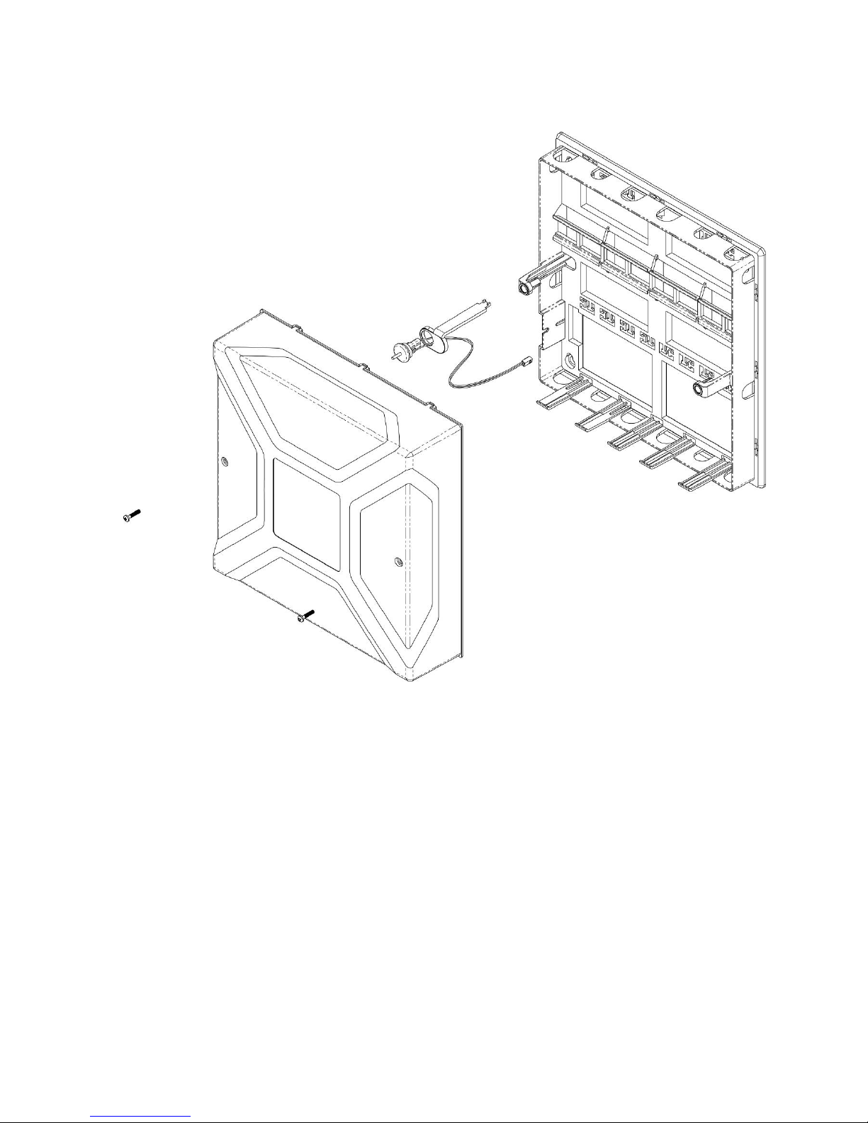
NXG-001 xGen Plastic Enclosure
The xGen enclosure features a DIN rail for mounting xGen modules, a tamper
switch, and integrated cable management.
The enclosure should be installed in accordance with EN50131-1 Environmental
Class II to provide operating conditions within:
• Temperature range: -10 to +55°C.
• Humidity range: Average 93% relative humidity, non-condensing
The lid can be removed by releasing the two screws using the supplied allen key.
Refer to drilling template provided with enclosure for mounting instructions.
To install a module, release the locking tab(s) and place on the DIN rail then
push the locking tab(s) to secure the module. To remove a module, use a small
flat-blade screwdriver to release the locking tab(s) on the xGen module then
remove from the DIN rail. Refer to module installation manual for further details.
Page 13
xGen Installation & Programming Guide 11
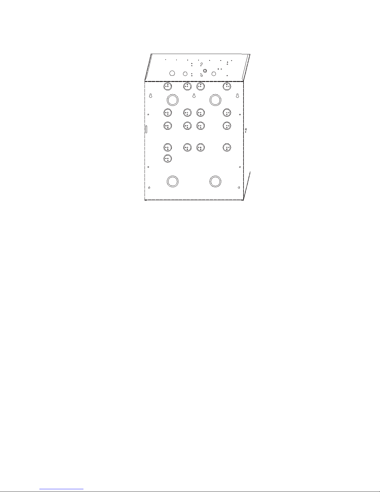
NXG-003 xGen Metal Enclosure
A spare metal enclosure is available for those installations where additional xGen
zone and/or output expanders are required or in case a larger backup battery is
required. The xGen NXG-003 metal enclosure includes a tamper switch and one
metal DIN rail. A second metal DIN rail (NXG-003-DIN) can be added if required
but in that case a backup battery of max 12 VDC / 7 Ah will fit the enclosure.
The enclosure should be installed in accordance with EN50131-1 Environmental
Class II to provide operating conditions within:
• Temperature range: -10 to +55°C.
• Humidity range: Average 93% relative humidity, non-condensing
To install a module, release the locking tab(s) and place on the DIN rail then
push the locking tab(s) to secure the module. To remove a module, use a small
flat-blade screwdriver to release the locking tab(s) on the xGen module then
remove from the DIN rail. Refer to module installation manual for further details.
Power Requirements
The xGen intrusion panel family is designed to be used with a 40 VA TD300E101F transformer (p/n NXG-003-X) which is included in the xGen panel. This
transformer includes a 500 mA 250 VAC fast blow replaceable fuse on the
terminal block.
Page 14
12 xGen Installation & Programming Guide
Grounding
All devices designed for the system have earth connections via metal studs to
the metal housing. Make sure that these metal studs make good connection to
the housing (beware of paint). The earth connections of every piece of equipment
in the system can be used for connecting the screen of shielded cables. If a
device is placed in a plastic housing the earth lug of the device does not have to
be connected.
In one building several cabinets or devices are earthed to a safety ground. The
safety ground for the building must be checked by a licensed contractor.
Shielding
The shielding of all shielded cables used in the system should only be connected
at one side to one common earthing point in a building. If a shielded LAN cable is
routed via more than one plastic device the shielding from incoming and outgoing
cable must be connected.
Termination Links
Put a jumper across TERM on the panel and the furthest device to ensure
correct RS-485 termination and avoid communication issues with signal
reflection, etc.
Page 15

xGen Installation & Programming Guide 13
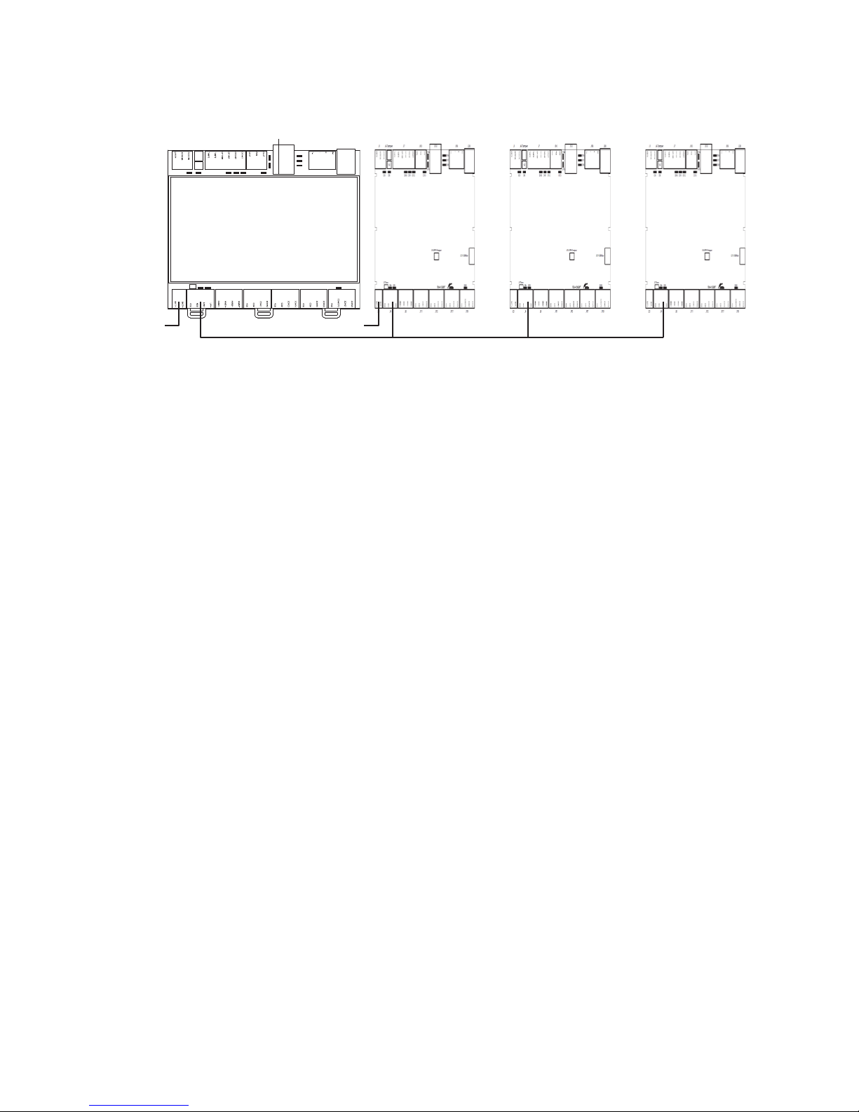
Cable requirements
The system RS-485 communication bus is used to connect keypads and inand output expanders to the xGen intrusion panel.
• Belden 8723, 2 pair twisted, shielded cable is recommended.
• 800 m total cable run on system.
• Max. 800 m from remote device to xGen control panel.
• Max. 32 devices plus panel.
• Max. 16 keypads, as part of the 32 device limit.
• Recommend a separate power supply for keypads 100 m away. If the keypad
is powered with a separate power supply, do not connect “12 V” from the
system LAN. Connect “+” of the local power supply to “+” on the keypad, and
connect 0 volts from the power supply and 0 volts from the system LAN+ to
the keypad terminal marked “D−”.
Page 16
14 xGen Installation & Programming Guide
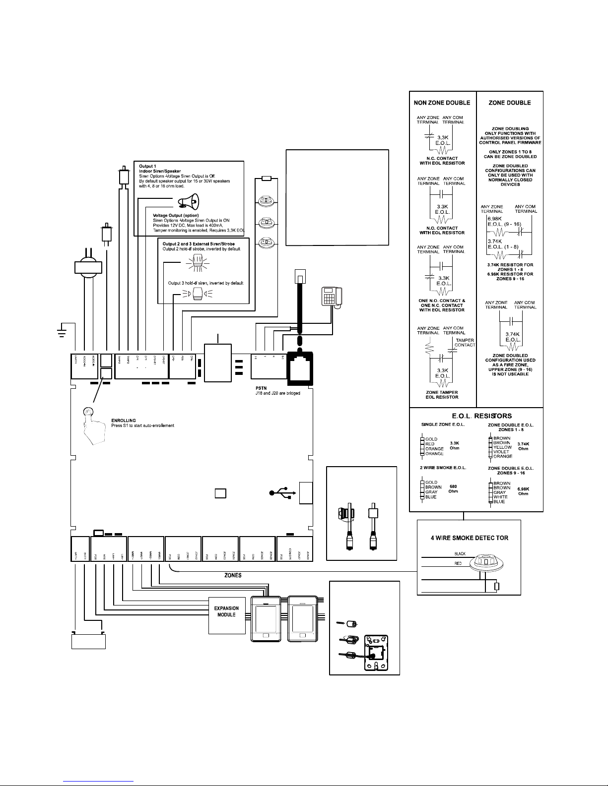
J21 USBNav
J16 SPKOutput
J1
J6
S1
D3 D10D5 D11 D12
J10J7 J13 J18 J20
D13
D15
D14
D18
D16
D17
D6 D9
J5Term
D20
J19J17J15J11J8J4J3
OP4- on J10
POS on J10
3.3K
COM
ZONE
-
+
680Ohm
-+
+
-
12V 7A
1...2...
TAMP1
Connect to main
J13
Install supplied ferrite
choke on Ethernet cable
before connecting
TAMP2
Optional tamper. Connect
to normally closed switch.
Apply wire short if not used.
Two Wire
Smoke
Phone Line
House Phone
x2
NXG-1820 Codepad
Install supplied ferrite
choke on bus cable
near codepad before
connecting
BELL
BELL
Ethernet
For 2-wire smoke
Enable Two Wire Smoke feature
Program Zone 8 as Fire Zone
EOL 680 ohm
For 4-wire smoke
Program Output 4 for Smoke Power
Program Zone as Fire
EOL 3K3
D6 Red LED – RS485 Transmitting
D9 Green LED – RS485 Receiving
D20 Red LED – Follows Output 5
panel tamper.
LEDs Bottom Row (left to right)
xGen Wiring Diagram
Page 17
xGen Installation & Programming Guide 15
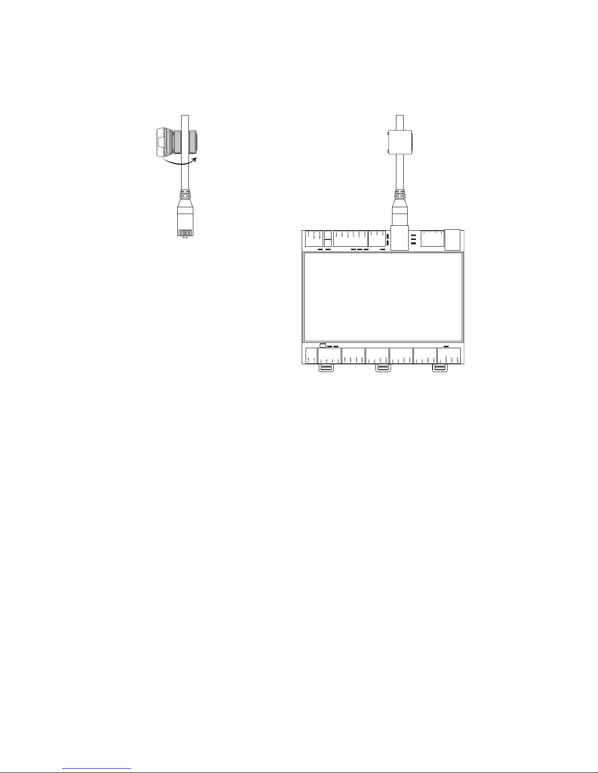
Ferrite Installation
Install the supplied ferrite on the Ethernet cable before attaching the cable to the
xGen intrusion panel.. This will prevent unwanted RF interference.
Page 18
16 xGen Installation & Programming Guide
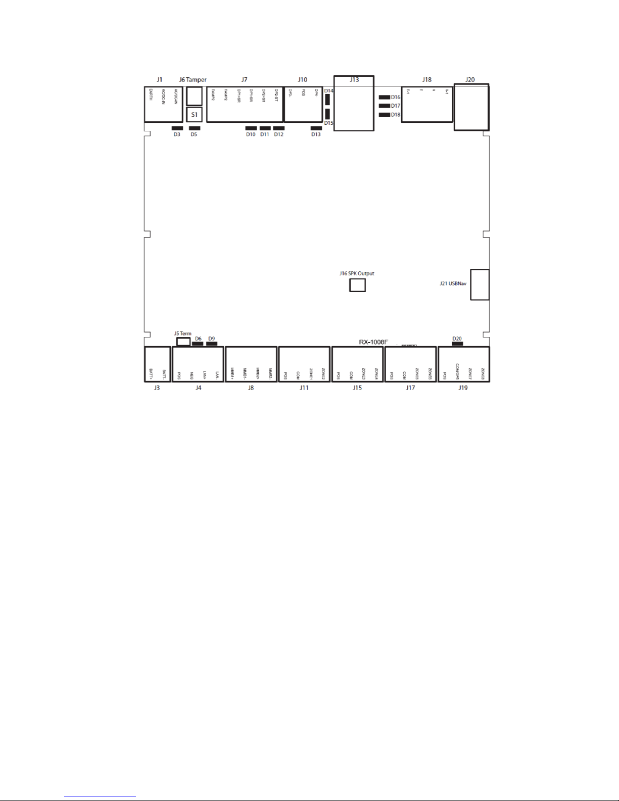
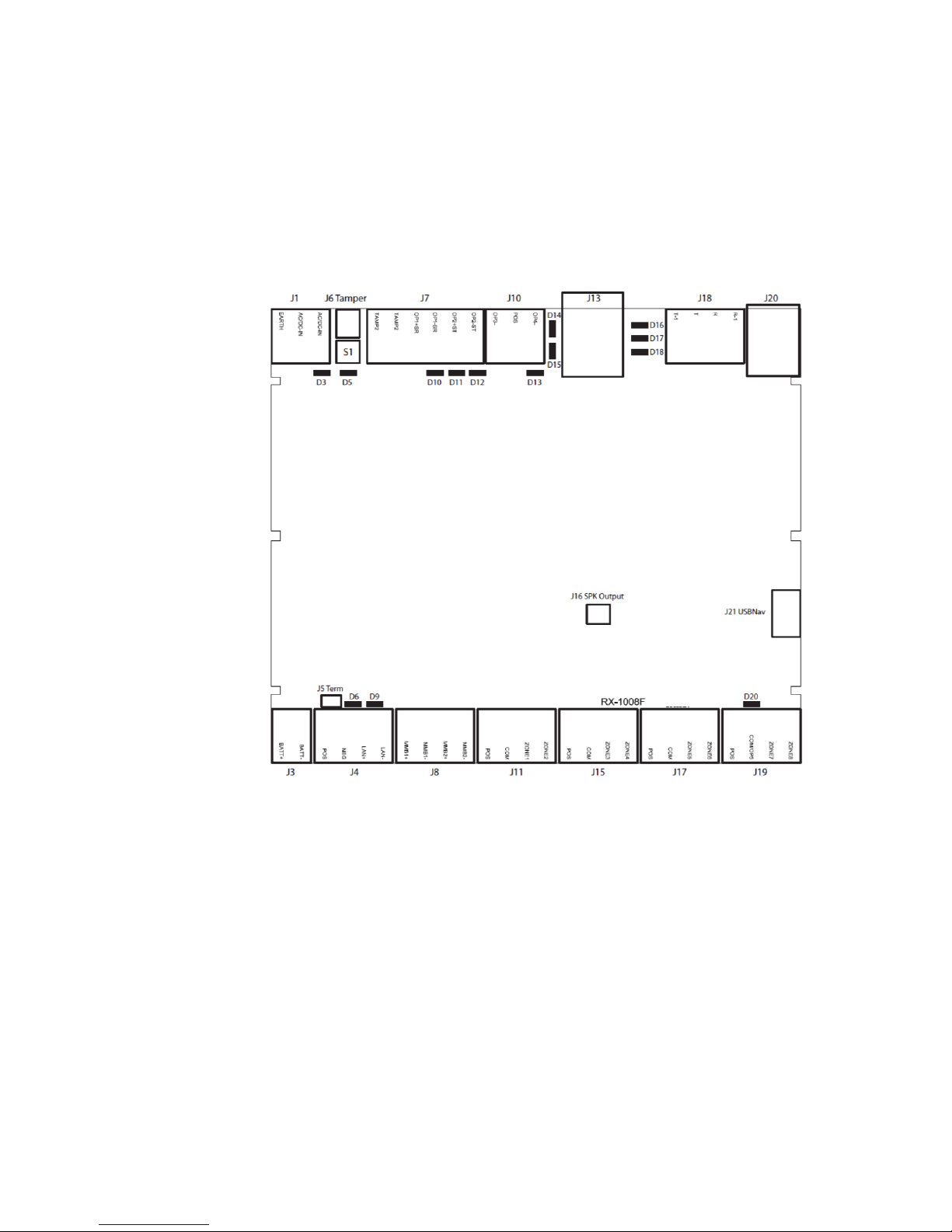
xGen Terminal Diagram
Left to right
• J1 – Terminals for power (16VAC 1.5A)
• J6 – Box Tamper
• S1 – Enrollment button, hold down for 3s to activate automatic device
enrollment feature, hold down while powering up to reset master user
• J7 – Terminals for Tamper 2, Output 1 (BELL output) and Output 2 (Outdoor
strobe)
• J10 – Terminals for Output 3 (Outdoor siren) and output 4 (power)
• J13 – RJ45 socket for IP/LAN connection
• J18 – Terminals for telephone line, bridged to J20
• J20 – RJ11 6P4C socket for telephone line, bridged to J18
• J16 – Connect to external speaker, this provides headphone level audio
output
• J21 – 5-pin connector for USBUP-EUR, used to upgrade firmware
• J3 – Terminals for backup battery
• J4 – Terminals for xGen RS-485 bus and power connection
Page 19
xGen Installation & Programming Guide 17
• J8 – Terminals for future use
• J11 – Terminals for Zone 1 and 2
• J15 – Terminals for Zone 3 and 4
• J17 – Terminals for Zone 5 and 6
• J19 – Terminals for Zone 7 and 8, can be configured to become Output 5
xGen LED Indicator Diagram
LEDs Top Row (left to right)
• D3 Red LED – 5 V internal power present
• D5 Red LED
• Enrollment mode active, slow flash means Automatic enrollment, fast flash
means Manual enrollment
• During a default it will toggle during each menu default
• When communicating over the phone line it will turn on when a valid
handshake tone or kiss off tone is present
• During a phone session it will turn on when a DTMF digit is detected
• D10 Red LED – follows Output 1 (BELL output), typically used for indoor
speaker
Page 20

18 xGen Installation & Programming Guide
• D11 Red LED – follows Output 2 (Strobe)
• D12 Red LED – follows Output 3 (Outdoor Siren)
• D13 Red LED – follows Output 4 (Power)
• D14 Red LED – Ethernet Link Present
• D15 Green LED – Ethernet Activity
• D16 Green LED – UltraConnect Ethernet Link Present
• D17 Green LED – UltraConnect 3G Link Present
• D18 Red LED – Heartbeat, should flash every second
LEDs Bottom Row (left to right)
• D6 Red LED – RS485 Transmitting
• D9 Green LED – RS485 Receiving
• D20 Red LED – follows Output 5 (Power)
Page 21

xGen Installation & Programming Guide 19
xGen Specifications
Mains power specifications
Mains input voltage 230 VAC +10%, −15%, 50 Hz ±10%
Current consumption at 230 VAC:
NXG-64 180 mA max.
Transformer output:
NXG-64 16.3 VAC, 40 VA
Power supply specifications
Power supply type
EN50131-6 Type A
for indoor use inside the supervised premises
Power supply voltage 13.8 VDC +/- 0.3 V
Power supply current
NXG-64 1.45 A max. at 13.8 VDC +/- 0.3 V
Main board consumption
NXG-64 100 mA at 13.8 VDC +/- 0.3 V
Maximum system current available
NXG-64 1350 mA at 13.8 VDC +/- 0.3 V
Auxiliary power output (AUX. POWER) 13.8 VDC +/- 0.2 V, 1 A max.
Battery power output (BAT) 13.8 VDC +/- 0.2 V, 400 mA max.
Battery type Lead acid rechargeable
BS127N: 7.2 Ah 12 V nominal
BS130N: 12 Ah 12 V nominal
BS131N: 18 Ah 12 V nominal
Maximum voltage at power supply, auxiliary 14.5 VDC
power output and battery power output
Battery low condition From 10.0 VDC to 11.0 VDC
Battery disconnect voltage 10.0 VDC
Maximum ripple voltage V, p-p 200 mV typical, 400 mV max.
General features
Code combinations From 10,000 (4 digits) to 100,000,000 (8 digits)
End-of-line resistor 680 Ω, 3.3 kΩ (default), 3.74 kΩ, 6.98 kΩ
Onboard zones 8 (default); 16 if zone doubling enabled.
Maximum zone number:
NXG-64(IP) 64
NXG-256IP 256
NXG-512IP 512
Additional inputs 2 - box tamper
Page 22

20 xGen Installation & Programming Guide
Onboard outputs 5 - BELL, strobe, siren and power outputs
Maximum output number 256
Maximum action number 256, main panel supports 32 actions,
each output module adds 32 actions, 7 output
modules will provide a maximum of 256 actions
Partitions:
NXG-64(IP) 96
NXG-256IP 32
NXG-512IP 96
Maximum keypad 16
Maximum expander 32 (including keypads)
Maximum user number:
NXG-64(IP) 100
NXG-256IP 256
NXG-512IP 256
User Permissions 128
Non-volatile Memory
Event log capacity 1024
Data retention (log, program settings) 10 years
Ethernet connection (IP only)
Supported standard IEEE 802.3u
Speed 10BASE-T or 100BASE-TX
Duplex Half-duplex and full-duplex
Cabling FTP (foiled twisted pair) Cat 5e cable or better
xGen bus
Type 4 wire RS485 bus
High common mode tolerance (25V)
Capacity Up to 32 devices
Range 800m
Recommended Cable Belden 8723 2 pair twisted shielded data cable
or exact equivalent
Current Consumption
Product Main description
Current Consumption
(non-alarm)
Current
Consumption (alarm)
NXG-64 64 zone panel no IP 100mA typical 100mA typical
NXG-64IP 64 zone panel /w IP 100mA typical 100mA typical
NXG-256IP 256 zone panel /w IP 100mA typical 100mA typical
NXG-256IP-M 256 zone panel /w IP 100mA typical 100mA typical
NXG-512IP-M 512 zone panel /w IP 100mA typical 100mA typical
NXG-1820-EUR Touchscreen keypad 100mA typical 175mA max
NXG-208 8 zone expander 25mA 25mA
NXG-220 20 zone expander 30mA 30mA
NXG-504 4 relay output expander
20mA idle
70mA 4 relays on
20mA idle
70mA 4 relays on
NXG-510 10 relay output expander
20mA idle
160mA 10 relays on
20mA idle
160mA 10 relays on
Page 23

xGen Installation & Programming Guide 21
Output Current Rating
Output Max Current Rating
Combined J10 POS, J7 Output 2+, J7 Output 1+ 1A max at 13.8VDC
J4 POS 1A max at 13.8VDC
Combined J11 POS, J15 POS, J17 POS, J19 POS 1A max at 13.8VDC
Auxiliary current and battery capacity
Discharge
Time
Charge
Time
7.2Ah Battery
(BS127N)
12Ah Battery
(BS130N)
18Ah Battery
(BS131N)
Reference
12 72 500 900 -
EN 50131 Grade
1 and 2
12 24 200 900 - INCERT
12 72 - - 1000
Not tested by
ANPI
12 24 - - n/a
Not tested by
ANPI
Example for NXG-64 EN Grade 2
When using battery backup as specified for EN Grade 2 using a 7.2Ah battery,
the maximum available auxiliary current is 500 mA.
Environmental
Operating temperature −10 to +55°C
Humidity 95% noncondensing
IP protection grade IP30
Colour White
EN 50131 grade and class Grade 2, Class II
NXG-1820E ACE classification Type A
Physical Dimensions and Weight
Product Main description Dimensions (LxWxH mm) Weight (g)
NXG-64 64 zone panel no IP 371 x 371 x 118 mm 2830 g
NXG-64IP 64 zone panel /w IP 371 x 371 x 118 mm 2830 g
NXG-256IP 256 zone panel /w IP 371 x 371 x 118 mm 2830 g
NXG-001 Plastic Enclosure 371 x 371 x 118 mm 1830 g
NXG-003 Metal Enclosure 475 x 395 x 130 mm 7150 g
NXG-1820-EUR Touchscreen keypad 18 x 82 x 125 mm 150 g
NXG-208 8 zone expander 135 x 80 x 55 mm 150 g
Page 24
22 xGen Installation & Programming Guide
NXG-220 20 zone expander 135 x 80 x 64 mm 180 g
NXG-504 4 relay output expander 135 x 80 x 55 mm 150 g
NXG-510 10 relay output expander 135 x 80 x 64 mm 180 g
NXG-64-CPU 64 zone panel no IP, CPU 147 x 127 x 58 mm 340 g
NXG-64IP-CPU 64 zone panel /w IP, CPU 147 x 127 x 58 mm 340 g
Fuses
Battery 4 A, resettable
12 V aux 2 A, resettable
System LAN 2 A, resettable
Output, high current output J10 POS |
Siren, high current output J7 OP1+ | 2A combined
Strobe, high current output J7 OP2+ |
Mains, mains fuse: 500 mA, fast 20x5
Note: Mains fuse is part of the mains terminal block.
Maintenance
No regular maintenance needed. System will report servicing when necessary
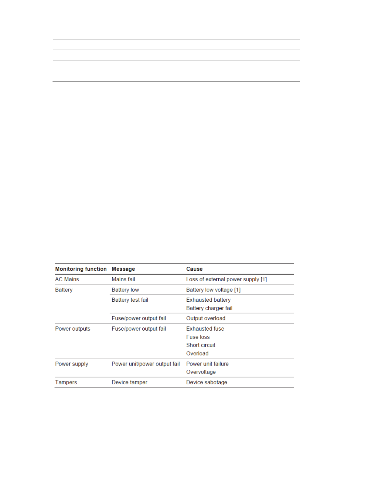
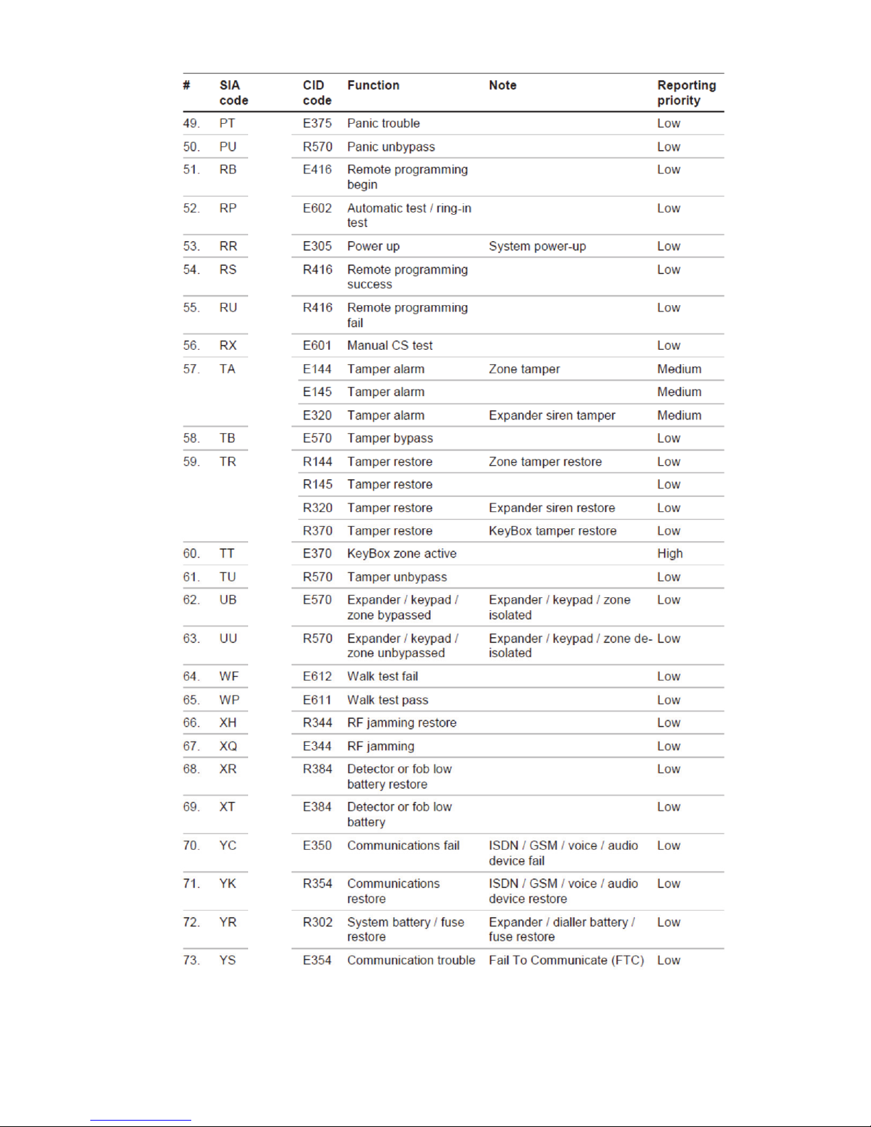
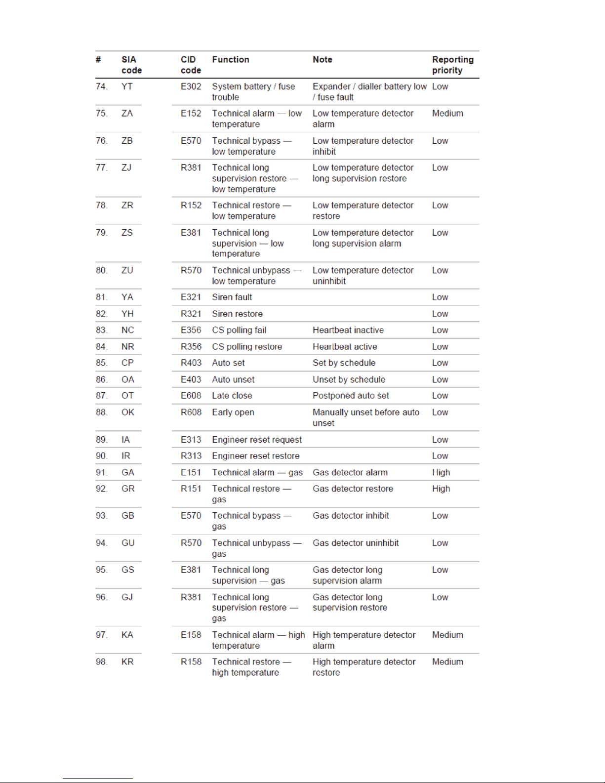
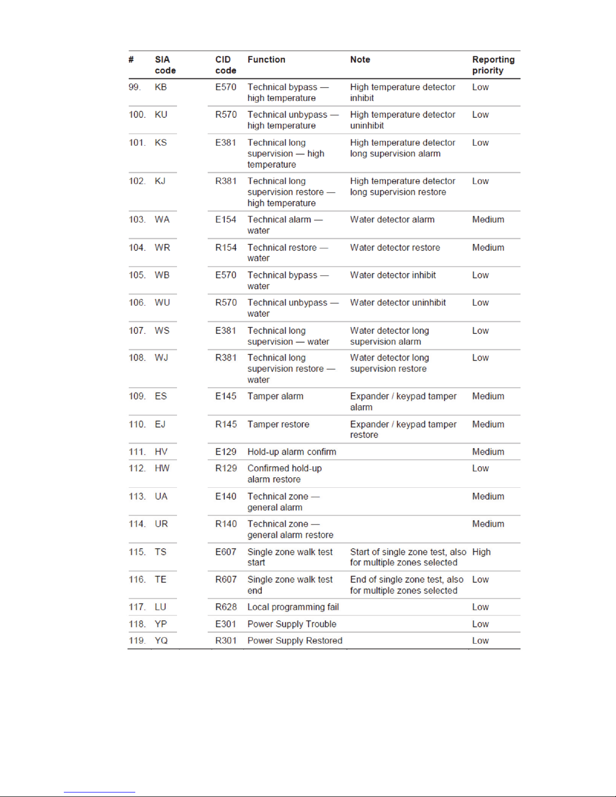
System monitoring
The system provides monitoring for the following items.
Page 25
xGen Installation & Programming Guide 23
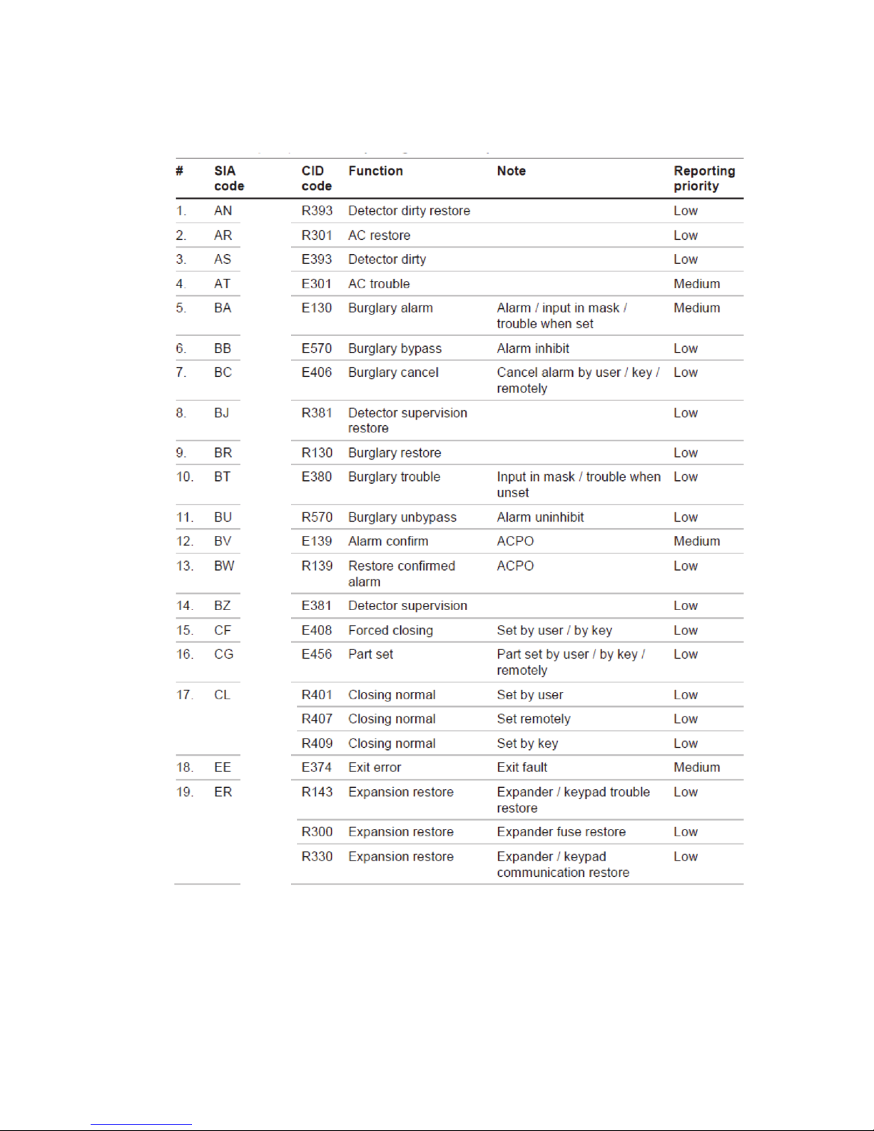
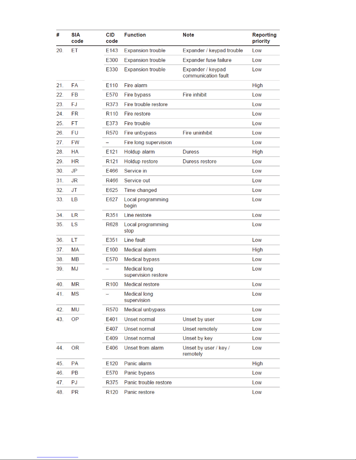
SIA and CID reporting code descriptions
Page 26
24 xGen Installation & Programming Guide
Page 27
xGen Installation & Programming Guide 25
Page 28
26 xGen Installation & Programming Guide
Page 29
xGen Installation & Programming Guide 27
Page 30

28 xGen Installation & Programming Guide
EN50131-3 Compliancy
In order to be compliant with the technical specification EN50131-3 (Alarm
systems – Control and indicating equipment), the following guidelines must be
taken into account:
• The tamper of the warning device should be connected to a 24 hour zone
input.
• Overriding is not supported with xGen. In case a zone is faulted, one shall
bypass the zone manually before arming or verify the zone and clear the fault.
See user instructions
• Hold-up zones are not allowed to be set for bypass
• Zone isolation is not supported
Options affected by EN 50131 regulations
EN 50131 Grade 2 Required settings
The following options and values are mandatory for EN 50131-1 Grade 2
regulations.
• Period, 24 h for every path to meet ATS Class 2, 4 h for the IP path to meet
Class 4.
• View Partitions and 2.2.1.n.3.4 Control Partitions settings are identical
• Buzzer silent, never
• Quick set, off
• Function keys, all set to None
• User group options, 25. No OP/CL reports option set to No
• Inhibit, set to No for all zones with type 5. Panic, 6. 24H
• Swinger shunt, set to Yes for all zones
• ACK on keypad, set to None for all zones with type 9. Keyswitch
• Entry time, 45 s maximum
• Entry alarms, Instant
• Active, set to No for all schedules.
• Activation, internal and external siren 90 to 900 s
• Delay time, external siren 600 s maximum
• Armed display, 30 s maximum
• Mains reporting delay, 3600 s maximum
• User code required, enabled
• Armed display, always
• Alarm list, disabled
Page 31

xGen Installation & Programming Guide 29
• Inhibit includes, all allowed except engineer reset, which must be disabled
• Pending alarms, enabled
• Swinger shunt ≥ 3
• Report restore, on ACK
• Line fault, enabled per path used
• Line fault delay, 0 s
• Refer to xGen Reference Manual for additional features, accessible at level 3
It is required to apply the following supervision settings for wireless expanders:
• Short supervision: 20 minutes
• Long supervision: 2 hours
• Smoke supervision: 4 hours
Caution: When any option, any additional function or any additional zone type in
this section does not comply with the EN 50131 requirements, the EN 50131
Grade 2 label must be removed from the system.
Optional Functions
• Detection of storage device – Failure
• Detection of low output voltage
EN 50131 compliance precautions
Installation
In order to install an EN 50131 compliant system, please make sure that all
system components are EN 50131 compliant.
Programming
Make sure that all system settings are in line with regulatory compliance
guidelines.
Size of log / event history
For full EN 50131 Grade 3 compliance, the system must store at least 500
events.
Marking
It is only allowed to mark the system with the EN 50131 Grade 2 label, if the
following requirements are met:
• All system components are EN 50131 compliant.
• All settings are done according to “EN 50131 Grade 2” on page 28.
If any of these two items is not valid, the EN 50131 Grade 2 label must be
removed from the system.
Page 32

30 xGen Installation & Programming Guide
Programming Methods
Once your hardware has been cabled and installed, there are four (4) ways to
program your xGen system:
Via DLX900 Management Software – The recommended way to program your
xGen system from a pc. DLX900 is compatible with Windows 7 and 8.
Via built-in xGen Web Server – Access all programming menus from the built-in
web browser from a pc without the need to install any software.
Via UltraConnect app – this provides access to the built-in xGen Web Server
via a smartphone app.
Via on-site keypad - The NXG-1820-EUR touchscreen offers a programming
menu allowing full system configuration. Refer to the NXG-1820-EUR installation
manual and xGen reference guide.
This manual will describe the steps needed to program each feature using the
DLX900 software. Screen shots of the xGen Web Server are also included for
your reference. Similar screens appear on the UltraConnect app.
If you are programming via a keypad, it is recommended you refer to the xGen
Reference Guide which will assist with navigating the menu structure.
Method 1 – DLX900 Management Software
The ideal method to manage your xGen is to use the DLX900 up/download
software. This is a fully featured management tool for alarm monitoring stations
and installation companies.
DLX900 supports a variety of connection methods:
1. Direct connection over LAN
2. Remote connection over UltraConnect (includes LAN or cellular)
3. Remote connection over dial-up PSTN
Connect to xGen using DLX900 on LAN
1. Turn on power to your system
2. Connect an Ethernet cable to the rear of the xGen and wait 10 sec for the
local router to assign the xGen an IP address if DHCP is available.
3. On the keypad press Menu – [PIN] – [ENTER] – Installer – Communicator –
IP Configuration – IP Address and note the IP address displayed.
4. Install DLX900 on a suitable computer,.
5. Start DLX900
6. Create a new customer
7. Enter the IP address of your system
8. Click Save
9. Click Connect via TCP/IP
Page 33

xGen Installation & Programming Guide 31
10. Click Read All
11. Refer to Programming Guide starting on page 55.
Connect to xGen using DLX900 on UltraConnect
In order for DLX900 to connect to an xGen panel you will need to know the
Download Access Passcode (under Communicator\Remote Access menu) and
the xGen unit must be enabled to allow remote connections (under
Communicator\IP Config).
1. Install DLX900 on a suitable computer, refer to DLX900 installation
instructions.
2. Start DLX900
3. Create a new customer
4. Enter the serial number, Download Access Passcode and Web Access
Passcode of the system
5. Click Save
6. Click Connect via TCP/IP
7. Click Read All
8. Refer to Programming Guide starting on page 55.
Connect to xGen using DLX900 on Dial-up
1. Install DLX900 on a suitable computer, refer to DLX900 installation
instructions.
2. Start DLX900
3. Create a new customer
4. Enter the Download Access Passcode of the system
5. Click Save
6. Click Connect via Dial-up
7. Click Read All
8. Refer to Programming Guide starting on page 55.
Method 2 – xGen Web Server
xGen has a built in web server which makes it easy and simple to set up your
system from a web browser instead of the keypad. This features:
• Simple forms to set up most commonly used features
• View system and zone status Arm and disarm partitions
• Bypass/Un-bypass zones
Page 34

32 xGen Installation & Programming Guide
• Turn chime mode on and off
• Add, remove and edit users
• Access to the advanced programming menu
Connect to xGen Web Server over LAN
1. Turn on power to your system
2. Connect an Ethernet cable to the rear of the xGen and wait 10 sec for the
local router to assign the xGen an IP address if DHCP is available.
3. On the keypad press Menu – [PIN] – [ENTER] – Installer – Communicator –
IP Configuration – IP Address and note the IP address displayed.
4. Open your web browser
5. Enter the IP address from step 3 and the xGen login screen should appear.
Some browsers may require you to enter http://
6. Enter your username and password, by default this is installer and 9713
7. You should now see a screen similar to:
Page 35

xGen Installation & Programming Guide 33
Troubleshooting
If you are unable to get an IP address in step 3, then your (wireless) router may
not be configured for automatic DHCP or certain security settings may be
enabled.
• Check your router settings and try again.
• On the xGen Touch Screen keypad press Menu – [PIN] – [ENTER] – Installer
– Communicator – IP Configuration – IP Options, this will allow you to modify
connection settings including DHCP.
• If the xGen panel is connected to a local router which provides internet
access, check the panel can connect to UltraConnect.
UltraConnect
UltraConnect is a cloud-based system that allows remote management and
remote access to an xGen system if enabled.
Check LAN Connection to UltraConnect
1. Login to the xGen Web Server as shown above
2. Click Settings
3. Select Connection Status in the drop down menu
4. Check:
• LAN Status should display “Connected”
• LAN Media should display “Ethernet”
• UltraConnect Status should display “Connected”
• UltraConnect Media should display “LAN ”
Page 36

34 xGen Installation & Programming Guide
If it does not:
1. Check cable connection.
2. Check router settings.
Connect to xGen via 3G modem
An optional 3G modem provides a back-up reporting path to the central
monitoring station over the 3G network if the Ethernet connection is not working.
The 3G modem can also be set for primary reporting in case there is no
LAN/internet connection available.
The 3G modem is pre-configured and does not require any programming. Once
plugged onto the xGen panel, the unit will automatically register itself on the
mobile network. If not, please refer the manual that comes with the cellular radio
for instructions on how to install it.
Check 3G connection to UltraConnect
1. Login to the xGen Web Server as shown above
2. Click Settings
3. Select Connection Status in the drop down menu
Page 37

xGen Installation & Programming Guide 35
4. Check:
• UltraConnect Status should display “Connected”
• Cell Service should display “Valid service”
• Signal Strength should display a value. Check your cellular radio manual
for acceptable values.
If it does not:
• Check the 3G connection:
1. Look at cell state, it should display “Connected”
2. Wait until cell state displays “Connected”, click Reload to refresh the
status
3. Check signal level in Menu 4, 5 – signal level should be between -91 to -
51
4. Contact Tech Support for assistance
• Check radio module is correctly installed
• Check radio antenna is correctly installed or moving antenna to a higher
location
• Check cable connection of Ethernet cable
• Check router settings
Valid service
Connected
-76
Page 38

36 xGen Installation & Programming Guide
Congratulations, your xGen system is now connected to your network and
UltraConnect. It is now ready to be programmed. Refer to Programming Guide
starting on page 55.
Method 3 – UltraConnect App
UltraConnect is a smartphone app that allows you to:
• Check the status of your system
• Arm and Disarm partitions
• Bypass zones
• Manage users
• Perform system programming
Access from the app is disabled by default for security. To allow access these
settings must be enabled on your xGen panel:
• Web Access Code
It permits remote access from the UltraConnect app. Set it to 00000000 to
prevent the app from connecting.
• User Name and PIN code
The UltraConnect app requires any user name and PIN code to log in to the
system and display features available to that user.
• Enable UltraConnect
Using web interface enable UltraConnect by selecting the option Settings –
Network – Enable UltraConnect
Set Web Access Code and User Name/PIN code
1. To enable the UltraConnect app click Settings
Page 39

xGen Installation & Programming Guide 37
2. Click Network
3. Enter a Web Access Passcode:
4. Tick “Enable UltraConnect” to enable email reporting via UltraConnect.
Features Email Reports UltraConnect App
Enable UltraConnect = OFF
Web Access Code = 00000000
No No
Enable UltraConnect = OFF
Web Access Code = not
00000000
Yes Yes
Enable UltraConnect = ON
Web Access Code = 00000000
Yes No
Page 40

38 xGen Installation & Programming Guide
Enable UltraConnect = ON
Web Access Code = not
00000000
Yes Yes
5. Enter a first name and PIN code:
Connect to xGen via UltraConnect App
UltraConnect is an app that allows you to control and program your xGen from an
Apple® iPhone/iPad, or Google Android device.
1. On your smartphone go to the Apple® App StoreTM or Google PlayTM store.
2. Search for UltraConnect.
3. Install the app.
4. Click the icon on your device to launch it.
5. Click + on the top right to add a new account, or the blue arrow to edit an
existing site.
6. Enter the details of your security system.
The serial number is printed on the back of the xGen panel. Alternatively log
in to xGen Web Server and go to Settings – Details to view it.
The default Web Access Passcode of 00000000 disables remote access. To
change it, log in to xGen Web Server and go to Settings - Network.
Page 41

xGen Installation & Programming Guide 39
The user name and PIN code is for any authorized user on the system. To
change these details, log in to xGen Web Server and go to Users.
7. Click Done button to save the details, then Sites to go back.
8. Click the name of the Site, the app will now connect you to xGen.
Using the App
The first screen that will appear once you connect is Arm/Disarm. This will
display the status of your system and allows you to arm or disarm partitions by
touching Away, Stay, or Off. From this screen you can also enable or disable
Chime mode.
The menu bar is located along the bottom of the app. Touch Zones to view zone
status. From the Zones screen you can touch “Bypass” to bypass a zone or
Page 42

40 xGen Installation & Programming Guide
touch it again to unbypass and restore the zone to normal operation. You may
also add or remove a zone from the Chime feature.
Touch Cameras to view any cameras connected to the system, this is a live view
of the camera. Touch Latest Clip to view the last recorded clip by that camera.
You can also access video clips linked to History events by touching Play Video
Clip from the History screen.
Page 43

xGen Installation & Programming Guide 41
You may also change your PIN code by touching Change PIN. Touch Save to
update your PIN code
Master users will have access to the full Users menu for creating and managing
users.
When you login with the installer account you will also have access to additional
menus for setting up and programming the xGen. Refer to the xGen Reference
Guide for additional help on the Advanced screen.
Page 44

42 xGen Installation & Programming Guide
Troubleshooting
• Check the serial number, web access passcode, user name and PIN codes
match those in the xGen
• Web Access Passcode must not be 00000000
• Web Access Passcode must be from 4 to 8 digits
• User Name must be entered with a space between the first and last name
and with correct capitalization
• If connected by Wired LAN, check the cable is plugged in and that the
connection is working
• Check Settings – Network – Enable UltraSync is ticked
• Check that your mobile device has access to the internet (e.g. open a web
browser)
• Try disabling WiFi on your device once the xGen is configured, and using the
3G/4G data connection of your device with the UltraSync app
• Check the UltraSync servers are correct under Advanced – UltraSync:
• Ethernet Server 1 - zw1.UltraSync.com:443
• Ethernet Server 2 - zw1.zerowire.com:443
• Wireless Server 1 - zw1w.UltraSync.com:8081
• Wireless Server 2 - zw1w.zerowire.com:8081
• Power cycle connected equipment including xGen and customer supplied
router(s)
Page 45

xGen Installation & Programming Guide 43
Recommended Items To Change
• Installer Code. This is the master key to most features. Always change this to
prevent accidental modifications by end-users and unauthorized access to the
security system.
• User 1 PIN code is 1234 at default. Always change this to prevent
unauthorized access to the security system.
• User 1 username is “User 1” at default, there is a space between “User” and
“1”. Usernames are required to provide access to the xGen Web Server and
UltraConnect app.
• Web Access Passcode. This provides access to the xGen Web Server,
UltraConnect, and UltraConnect app.
• Enable remote access for DLX900. The default Download Access Passcode
of 84800000 allows remote access. Login to the xGen Web Server and go to
Settings – Network to change the code:
Page 46

44 xGen Installation & Programming Guide
Note: To disable DLX900 access change the Download Access Code to
00000000.
Page 47

xGen Installation & Programming Guide 45
System Status Messages
Various messages may appear on the Status screen of xGen Web Server and
UltraConnect app.
System
• AC power fail – The security system has lost its electricity power
• Low battery – The security system’s back up battery requires charging
• Battery test fail – The security system’s back up battery requires changing
• Box tamper – The security system’s cabinet tamper input has activated
• Siren trouble – The security system’s external siren has a problem
• Over current – The security system is drawing too much current
• Time and date loss The security system time and date need resetting
• Communication fault – The security system has detected a problem with the
phone line
• Fire alarm – A fire alarm has been activated from the xGen unit
• Panic – A panic alarm has been activated from the xGen unit
• Medical – A medical alarm has been activated from the xGen unit
Partition Number. Partition Name
• Is On in the away mode – This Partition is armed in the away mode
• Is On in the stay mode – This Partition is armed in the stay mode
• Is ready – This Partition is secure and ready to be armed
• Is not ready – This Partition is NOT ready to be armed, a zone is not secure
• All Partitions are on in the away mode – All Partitions in this multi partition
system are armed in the away mode
• All Partitions are on in the stay mode – All Partitions in this multi partition
system are armed in the stay mode
• All Partitions are ready – All Partitions in this multi partition system are secure
and ready to be armed
Zone Number. Zone Name
• In Alarm – This zone has triggered a system alarm condition
• Is bypassed – This zone is isolated (disabled) and will not activate an alarm
• Chime is set – This zone is part of the chime group
• Is not secure – This zone is not closed
• Fire alarm – This zone has triggered a fire alarm
• Tamper – This zone has triggered a tamper alarm
• Trouble fault – This zone has an open circuit
Page 48

46 xGen Installation & Programming Guide
• Loss of wireless supervision – This zone is a wireless device and has lost its
communication link with the control panel
• Low battery – This zone is a wireless device and needs its battery changed
App and Web Error Messages
Various error messages may appear in the xGen Web Server and UltraConnect
app.
Advanced/Settings Configuration Menus
• "You must select a Menu before you can scroll" – An attempt was made to
scroll up or down from the top level menu.
• "Select a submenu from the list or select back to access the main menu" – An
attempt was made to scroll up or down from a submenu that has no additional
levels
• "Defaulting requires 2 levels" – a Shortcut was entered without two levels.
Read Write errors and results
• "Write Access Denied"
• "Nothing displayed can be Saved"
• "Program Success!"
• "Name Saved"
Zones Page
• "No Zones Configured For Your Access" – Displayed on Zones page when
there are no zones available to view
WiFi
• "Connection Was lost before a response was received" – Sent when No
response received on a WiFi network change
Data Entry Errors
• "Data must only contain the following characters"
• "Date must be of the form YYYY–MM–DD."
• "Day must be from 1 to 31"
• "Data entry must only contain the numbers 0 – 9 and A–F"
• "Data entry must only contain the numbers 0 – 9"
• "Data must be a number from X to Y"
• "Improper Time Value"
• "must be 4 to 8 digits
• "You must enter a user Number between 1 and 1048575"
Page 49

xGen Installation & Programming Guide 47
• "PIN digits must be between 0 and 9"
• "PIN Must be 4–8 digits from 0–9"
• "Data must not contain the following characters []"
Page 50

48 xGen Installation & Programming Guide
Arming and Disarming Your System
You may arm and disarm partitions from a NXG-1820 keypad.
Only users with an authorized user code (Level 2 user) will be allowed to use the
xGen alarm system. Users with no valid user code (Level 1 user) do not have
access as defined by EN 50131-3.
Keypress Tamper
The NXG-1820-EUR keypad will be locked in screensaver mode when unused
for a preset time.
A valid PIN is required to unlock the screen and access the system. Users can
set PIN codes between 4 and 8 digits in length.
When an incorrect PIN is entered ten times the keypad is locked for 90 seconds
and the screen will display a lock icon. During this time the keypad will not be
operational and PIN codes cannot be entered.
After the 90 seconds expires, if the first PIN attempt is incorrect the 90 second
timer will start again. If the PIN code is valid, then the counter will reset and a
further ten attempts can be accepted.
Note: EN 50131 Grade 2 required settings - There are no disallowed
account codes. 5 digits minimum to provide 10,000 possible combinations.
Arm Your System In Away Mode
Touch the Away or Away + button to arm your system in Away mode:
If your system has multi-Partition control enabled, the Away + button will be
displayed.
A valid PIN code will need to be entered to determine what permissions they
have, this includes which Partitions and at what time/day that user has access.
Arm Your System In Stay Mode
Touch the Stay or Stay + button to arm your system in Away mode:
If your system has multi-Partition control enabled, the Stay + button will be
displayed.
A valid PIN code will need to be entered to determine what permissions they
have, this includes which Partitions and at what time/day that user has access.
Page 51

xGen Installation & Programming Guide 49
Disarm One Or More Partitions
Touch the Off or Off + button to arm your system in Away mode:
If your system has multi-Partition control enabled, the Off + button will be
displayed.
A valid PIN code will need to be entered to determine what permissions they
have, this includes which Partitions and at what time/day that user has access.
Activate SOS Feature
Touch the SOS button to display the SOS feature:
On this screen touch and hold the appropriate button for 2 seconds to activate
Manual Fire Alarm, Manual Medical Alarm, or Manual Panic Alarm.
Depending on how your system is programmed, the control room may receive
the corresponding event. Check with your control room to determine what action
will be taken.
If silent alarm is enabled, then the keypad will not display any signs that the panic
button was pressed.
To cancel a SOS alarm – return to the home screen, touch the Status button and
turn the Partition off.
Page 52

50 xGen Installation & Programming Guide
Configure Email Reporting
1. Login to xGen Web Server or UltraConnect app. Use an installer or master
user account.
2. Click Settings
3. Click Channels in the drop down menu
4. Click “Select Channel to Configure” where the Format is already set to Email
5. Enter an email address
6. Select an Event List
7. Enter a Channel Name for future reference
8. Click Save
Installer and Engineer user types can customize Event List for selective
reporting.
Page 53

xGen Installation & Programming Guide 51
xGen building blocks
On the following page is the system diagram of xGen showing all the different
building blocks that can be used to create an xGen system.
You have full flexibility to customise your system. Program each building block in
turn to complete your system. We suggest left to right, top to bottom. Refine
blocks as you go or use presets to save you time.
The smaller grey blocks indicate related blocks that are used by the larger blue
block.
The number on the bottom right of each block indicates the capacity of the
system.
Page 54

52 xGen Installation & Programming Guide
System Diagram
Partitions
a) Partition Options
b) Partition Timers
c) Partition Reporting
Zone Types
- Partition Armed
- Partition Disarmed
Zone Options
Event Lists
Partition Groups
Channels Channel Groups
Schedule
Channel Groups
Channel Groups
Holidays Schedules Permissions
a) Groups
b) Options/Timers
User
a) Main
b) Advanced
Permissions
Schedules
Menus
Partition Groups
Channel Groups
A
ction Groups
Menus
a) Setup
b) Security…
c) History…
d) Communications
e) Times…
Actions
Holidays
up to
256*
32
32
128
16 16
4
96 128 up to
256*
up to
512*
up to
96*
Zone Type
Zone Options
Partition Group
Schedule
User
Communicator
a) General Options
c) IP Config
d) Ethernet
d) Radio
d) Dial IP
d) Email
e) Remote Access
f) System Event Reporting
System
a) System Clock
b) System and Siren
c) Timers
d) Maintenance and Test
Zones
a) Profile 1
b) Profile 2
16
Arm/Disarm
User
Schedule
96
Action Groups
64
Devices Outputs
zone expanders, keypads,
transmitters
Communicator
Event Lists
64
Actions
Channels
Partitions
UltraConnect
Scenes
16
Actions
Schedules
Speech Tokens
Permissions
Schedules
64
Cameras
16
256
[*] For the maximum number of zones, partitions and users in the particular xGen panel version,
see "xGen Specifications" on page 19.
Page 55

xGen Installation & Programming Guide 53
Presets – just click and go!
Presets make it quick to program a system without needing to program every
detail.
Most menus in xGen have presets pre-programmed for your convenience, simply
select from the drop-down menu the most suitable option.
For example, using the built-in presets you can quickly create a new user and
assign them Arm/Disarm permission for Partitions 1-2 during normal office hours
and no access during holidays.
Page 56

54 xGen Installation & Programming Guide
Create your own presets by assigning a name for the settings you most
commonly use. This will save you time when programming and maintaining the
system.
Programming with Presets
Use presets to configure the first 10 menus for faster setup:
Menu 1 - User
Menu 2 - System Options
Menu 3 - Zones
Menu 4 - Partitions
Menu 5 - Channels
Menu 6 - Communicator
Menu 7 – Schedules
Menu 8 – Actions
Menu 9 – Arm-Disarm Number
Menu 10 – Devices
xGen is fully customizable for maximum flexibility. Should a preset not be
available for your requirements then Menus 11 and higher provide access to
more detailed programming settings.
When naming presets and labels, the following characters cannot be used ? = %
& " / < > ;
Page 57

xGen Installation & Programming Guide 55
Programming Guide for xGen
Page 58

56 xGen Installation & Programming Guide
Quick Start Guide
Short form programming sheet for a monitored system
This is not a substitute for reading the manual
1. Hard Default Panel Unplug battery & remove power, turn on power,
Enter 971300 within 10 seconds,
2. Soft Default Panel Login to web console,
shortcut 910.910, wait 12 seconds
3. Go To Program Mode Menu
4. Change Program Code Menu, Users
5. Duress Code
6. System Options System, System and Siren Options,
DEOL, Box Tamper
7. System Timers Siren, Strobe, Phone Fault, AC Fail
8. Program Zones Zones, use presets for type, options, and
assigning Partitions
9. Program Partitions Partitions, Partition 1 name, Force Arm,
Partition Entry/Exit Timers
10. Reporting Partition 1, Partition Reporting,
Account Number and Channel Group
11. Set up Receiver Phone #1 Communicator, Channel 1, Account Code,
Format, Phone/Email,
Event List 1
12. Set up Receiver Phone #2 Communicator, Channel 2, Account Code,
Format, Phone/Email,
Event List 1
13. Communicator Communicator, IP Config
14. Download Access Code Communicator, Remote Access
15. Download Control (Remote Access) Communicator, IP Config
16. Autotest
17. Medical Alarm Sounder “ON”
18. Auto Test Control
19. Exit Program Mode
20. Change Master Code (default 1234)
21. Program User Codes Users
22. Set Date & Time Communicator, IP Config
or manually set in System, System Clock
23. Test Testing, Walk Test, Siren Test,
Communicator Test
24. Train Client/End User
Note: If testing reporting, master code does not send open/closing reports by default (see
Feature 2).
Page 59

xGen Installation & Programming Guide 57
Programming Instructions for System Options
Goal
Program System Options including time and date, tamper, siren, timers, and
service settings.
Pre-conditions
If you want time and date to be automatically updated then check internet time
server is enabled under Communicator – IP Config.
If you want to allow xGen to send diagnostic emails then check email is set up
correctly under Communicator – Email and xGen is connected to a network.
Note: Ensure you set the correct time zone here.
Menu Overview
Instructions
1. Open System
2. Select the right Time Zone using the Hours and minutes offset
3. If you wish to update the time and date
2. System
a) System Clock
b) System and Siren
c) Timers
d) Maintenance and Test
Page 60

58 xGen Installation & Programming Guide
4. Go to System and Siren Options
5. Select the settings you want to enable
6. Go to Timers
7. Enter the settings for global timers. Note Entry/Exit times are not here, go to
Partitions-Partition Timers.
Page 61

xGen Installation & Programming Guide 59
8. Go to Maintenance and Test
9. Enter a Diagnostic email interval. This is the number of days to wait before
sending an email at the specified time. This verifies email communication is
working.
Page 62

60 xGen Installation & Programming Guide
Web Page
Page 63

xGen Installation & Programming Guide 61
Programming Instructions for Permissions
Goal
Create a list of permissions that will restrict users, keypads, and devices to
specific parts of the system.
Pre-conditions
Have programmed or customized Channel Groups, Partition Groups, Menus, and
Action Groups. Alternatively you can use the preset groups.
Menu Overview
12. Partition Groups
11. Permissions
a) Groups
b) Options/Timers
13. Menus
12. Partition Groups
18. Channel Groups
19. Action Groups
18. Channel Groups
1. User
a) Main
b) Advanced
11. Permissions
7. Schedules
10. Devices
Outputs
zone expanders, keypads,
transmitters
11. Permissions
7. Schedules
13. Menus
a) Setup
b) Security…
c) History…
d) Communications
e) Times…
19. Action Groups
Page 64

62 xGen Installation & Programming Guide
Instructions
1. Open Permissions
2. Select the permission number you want to modify
3. Enter a functional name for the permission.
4. Select the Groups for each item which will give access to the items selected
inside the group. For example, if this permission is assigned to a user, then
that user will have access to Arm each of the Partitions that are selected
inside the Partition Group and no others.
5. Click the Options/Timers tab
Page 65

xGen Installation & Programming Guide 63
6. Select the user options that you want to apply to this permission. Descriptions
of each item are available in the xGen Reference Guide.
Next
• Program Users or Devices
Programming Instructions for Menus
Goal
Create a list of menus that a user or device has access to on the xGen system.
Pre-conditions
None.
Notes:
The menus that will be available are the ones that the device has
permission to display AND the ones that a user has access to, at the
specified time and date which is controlled by Schedules.
Users have up to 4 levels of access and devices have up to 2. This allows
very sophisticated and fine grained control of access.
64 custom menus can be created. The preset ones will help you create a
system quickly without needing to modify these.
Menu Overview
11. Permissions
a) Groups
b) Options/Timers
13. Menus
12. Partition Groups
18. Channel Groups
19. Action Groups
10. Devices
Outputs
zone expanders, keypads,
transmitters
11. Permissions
7. Schedules
13. Menus
a) Setup
b) Security…
c) History…
d) Communications
e) Times…
1. User
a) Main
b) Advanced
11. Permissions
7. Schedules
Page 66

64 xGen Installation & Programming Guide
Instructions
1. Open Menus
2. Select the Menu number
3. Enter a descriptive name
4. Tick each item that you want a user / device to have access to.
Next
• Program Permissions
• Assign the Permission to a User or a Device
Programming Instructions for Holidays
Goal
Create a list of holidays to provide or prevent access to the xGen system on the
specific dates.
Pre-conditions
None.
Notes
Ticking Holidays in a Schedule for a permission PREVENTS access.
Page 67

xGen Installation & Programming Guide 65
Holiday schedules may impact automation features such as Actions if they
are in use. For example you may not want an Action to play on a holiday,
so take care in programming the associated Schedule and permissions.
Menu Overview
Instructions
1. Open Holidays
2. Select one of the 4 Holidays available
3. Enter a name for the Holidays
4. Enter the start and end date for each holiday you have
Next
• Program Schedules
14. Holidays
7. Schedules
14. Holidays
Page 68

66 xGen Installation & Programming Guide
Example
An office is not staffed during a public holiday and you want to prevent access to
the building to staff on this date.
The public holidays in NSW, Australia for 2015 are:
New Year's Day Thursday, 1 January
Australia Day Monday, 26 January
Good Friday Friday, 3 April
Easter Saturday Saturday, 4 April
Easter Sunday Sunday, 5 April
Easter Monday Monday, 6 April
Anzac Day Saturday, 25 April
Queen's Birthday Monday, 8 June
Labour Day Monday, 5 October
Christmas Day Friday, 25 December
Boxing Day Saturday, 26 December
#Additional Day Monday, 28 December
Office Worker
User Permission 1 – All Partitions
Office Schedule 1 – 8am-8pm M-F,
Holidays 1 (ticked)
Page 69

xGen Installation & Programming Guide 67
We would open Holidays and program these date ranges:
Next, go to Schedules and tick “Holidays 1”:
Page 70

68 xGen Installation & Programming Guide
Then assign that schedule to the User:
Programming Instructions for Users
Goal
Add/Edit/Remove users from your xGen system.
Pre-conditions
Have programmed or customized Permissions. Alternatively you can use
the presets.
Have programmed or customized Schedules. Alternatively you can use
the presets.
Notes
PIN codes must be unique across the system, no two users can share the
same PIN code.
PIN codes must be 4 to 8 digits in length.
Note: EN 50131 Grade 2 Required settings 5 digits minimum
User name must be assigned to give that user access to UltraConnect app
or xGen Web Server. A user with no first name will be unable to gain
remote access.
The default installer account is User 256 with user name installer and PIN
9713, with Master Engineer user type. These details are used to login to
the xGen Web Server web pages and UltraConnect app.
The default master account is “User 1” and PIN 1234
The default standard account is “User 2” and PIN 5678
Page 71

xGen Installation & Programming Guide 69
Menu Overview
Instructions
1. Open Users
2. Select the User number you want to modify with the Left and Right arrow keys
on the top right. You can also Search, Add, Copy, and Delete a user by
clicking the corresponding button on the toolbar.
3. Enter a first name and/or last name for the user. It is case sensitive and
provides the user name to login from the UltraConnect app.
4. Enter a new PIN code for the user. It must be unique and 4-8 digits long.
5. Select the user type that you want to apply to this user. Descriptions of each
type are available in the xGen Reference Guide.
6. The Status option determines if that user can interact with the system, or if
their access has expired, or has Lost their card.
7. Click the Advanced tab.
11. Permissions
a) Groups
b) Options/Timers
13. Menus
12. Partition Groups
18. Channel Groups
19. Action Groups
1. User
a) Main
b) Advanced
11. Permissions
7. Schedules
7. Schedules
14. Holidays
Page 72

70 xGen Installation & Programming Guide
8. You can set the start/end date and time for when this user will have access to
the system. This can be used to provide temporary user access. If Active is
selected on the previous tab then the end date and time on this screen will be
set to maximum.
9. You can program up to 4 levels of different access using Permissions and
Schedules. Permission Profile 1 is the highest level and will override
Permission Profile 2 when Schedule 1 becomes active. Refer to xGen
Reference Guide for more details.
Page 73

xGen Installation & Programming Guide 71
Web Page
Programming Instructions for Zones
Goal
Program zones and add them to Partitions.
Pre-conditions
None.
Notes
Use presets for Zone Types and Zone Options to quickly set up your
system.
Zones can have one or two profiles. The first profile will be active during
the selected schedule, it takes priority over the second profile/schedule.
The second profile will be active during the selected schedule if the first
profile is not active.
Page 74

72 xGen Installation & Programming Guide
If no schedule is set (or is currently active) in either the first or second
zone profile then the zone will be disabled.
See the next section for programming custom zones.
Menu Overview
Instructions
1. Go to Zones.
2. Select a zone number you want to program.
3. Enter a name for the zone.
4. Select a zone type preset.
15. Zone Types
- Partition Armed
- Partition Disarmed
16. Zone Options
15. Zone Type
16. Zone Options
12. Partition Group
7. Schedule
1. User
3. Zones
a) Profile 1
b) Profile 2
7. Schedules
14. Holidays
4. Partitions
a) Partition Options
b) Partition Timers
c) Partition Reporting
12. Partition Groups
7. Schedule
18. Channel Groups
Page 75

xGen Installation & Programming Guide 73
5. Select a zone options preset.
6. Select a Partition group for the zone. If you want a zone to be in its own
Partition then select a Partition group with only one Partition. To create a
zone in a common Partition, select a Partition group with multiple Partitions.
Alternatively come back to this step later.
7. For a standard installation set the schedule to a preset which is 24 hours
every day, holidays should NOT be ticked in this schedule. This will enable
the first zone profile.
If you want the zone settings to change based on a schedule, then select the
first schedule here.
8. If you are setting up a keyswitch zone then the user number field controls
which user profile will be used to arm/disarm that Partition. When this zone is
activated then it will report as this user number.
9. If you are programming a second zone profile, then go to that now and repeat
steps 4-7.
Web Page
Page 76

74 xGen Installation & Programming Guide
Next
• Zones are assigned to one or more Partitions using Partition Groups. If
necessary program Partitions and Partition Groups, then assign a Partition
Group to each zone (step 6).
Programming Instructions for Custom Zones
Goal
Program zones with advanced customization of settings.
Pre-conditions
Program the schedule you want the zone to follow if needed. Alternatively use
the presets.
Menu Overview
15. Zone Types
- Partition Armed
- Partition Disarmed
16. Zone Options
15. Zone Type
16. Zone Options
12. Partition Group
7. Schedule
1. User
3. Zones
a) Profile 1
b) Profile 2
7. Schedules
14. Holidays
4. Partitions
a) Partition Options
b) Partition Timers
c) Partition Reporting
12. Partition Groups
7. Schedule
18. Channel Groups
Page 77

xGen Installation & Programming Guide 75
Instructions
1. Go to Zone Type.
2. Go to Zone Options.
Page 78

76 xGen Installation & Programming Guide
3. Select the options you want, the SIA/CID event code can be customized. See
the xGen Reference Guide for a table of codes.
4. Go to Zones.
5. Select a zone number you want to program.
6. Enter a name for the zone.
7. Select the zone type profile you just created.
8. Select the zone options profile you just created.
9. Select a Partition group for the zone. If you want a zone to be in its own
Partition then select a Partition group with only one Partition. To create a
zone in a common Partition, select a Partition group with multiple Partitions.
Alternatively come back to this step later.
10. For a standard installation set the schedule to a preset which is 24 hours
every day, holidays should NOT be ticked. This will enable the first zone
profile.
If you want the zone settings to change based on a schedule, then select the
first schedule here.
If no schedule is set in either the first or second zone profile then the zone will
be disabled.
11. If you are setting up a keyswitch zone then the user number field controls
which user profile will be used to arm/disarm that Partition. When this zone is
activated then it will report as this user number.
12. If you are programming a second zone profile, then go to that now and repeat
steps 4-7.
Page 79

xGen Installation & Programming Guide 77
Next
• Zones are assigned to one or more Partitions using Partition Groups. If
necessary program Partitions and Partition Groups, then assign a Partition
Group to each zone (step 8).
Programming Instructions for Partitions
Goal
Program Partitions, Entry/Exit Times, Reporting Options, and Partition Groups.
Pre-conditions
Programmed Communicator, Channels, and Channel Groups.
Notes
Partition Counting requires an xGen Door Controller module to function.
Page 80

78 xGen Installation & Programming Guide
Menu Overview
Instructions
1. Go to Partitions
2. Select a Partition Number
3. Enter a descriptive name
4. Select the Options you want to enable for this Partition. Partition 2 and above
have “Use Partition 1 Options” ticked to allow faster programming of your
18. Channel Groups
6. Communicator
a) Options
b) IP Config
c) Ethernet
d) Radio
e) Dial IP
f) Email
g) Remote Access
h) System Event Reporting
5. Channels 18. Channel Groups
6. Communicator
17. Event Lists
4. Partitions
a) Partition Options
b) Partition Timers
c) Partition Reporting
12. Partition Groups
7. Schedule
18. Channel Groups
Page 81

xGen Installation & Programming Guide 79
system. Untick this box if you want to customize options for Partition 2 and
above.
5. For advanced programming you can assign a Schedule and a Partition Time
Disarm function to occur according to the schedule. Refer to the xGen
Reference Guide for more details.
6. Go to Partition Timers
7. Enter the timers that apply to this Partition
8. Enter the maximum users allowed in this Partition. This is an access control
feature and requires the use of a Door Controller Module.
9. Go to Partition Reporting
Page 82

80 xGen Installation & Programming Guide
10. Assign the Partition an account number and the Channel Group you want this
Partition to report to. See Programming Instructions for Zone Reporting for
more details on how this works.
Next
• Customize Partition Groups if needed.
Page 83

xGen Installation & Programming Guide 81
Webpage
Programming Instructions for Schedules
Goal
Create a schedule to provide or prevent access to the xGen system on the
specific dates and times.
Pre-conditions
Holidays have been programmed if needed.
Notes
Ticking Holidays in a Schedule PREVENTS access on the holiday dates.
Page 84

82 xGen Installation & Programming Guide
xGen automatically handles schedules that span midnight (e.g. bakers hours), do
not tick the following day of the AM hours. (See Reference Guide for more
details)
Menu Overview
Instructions
1. Go to Menu 7 – Schedules
2. Enter a name for the Schedule.
3. Select the first Start and End time.
4. Select the days you want this start and end time to apply to.
5. If you are using the DLX900 software you will be able to see 4 sets of times
and days, click the drop down in the middle to access more. Each schedule
can have up to 16 sets of times and days.
18. Channel Groups
14. Holidays
7. Schedules
14. Holidays
Page 85

xGen Installation & Programming Guide 83
If you are using a TouchNav, press the Up and Down buttons to access the
16 sets of times and days.
6. To allow an Action to control when this Schedule is active/inactive, select the
Follow Action Number.
7. Now the schedule is ready to be assigned to a User or used by another part
of the system.
Page 86

84 xGen Installation & Programming Guide
Webpage
Page 87

xGen Installation & Programming Guide 85
Example
For example, you could create a 24/7 schedule and then have this schedule
follow an action. Next assign a keypad permission this schedule. Now based on
what the action does, we can conditionally enable or disable a keypad. This
provides a high level of flexibility and multiple sets of rules using actions can be
set up like this.
Programming Instructions for Arm-Disarm
Goal
Automatically Arm and Disarm your xGen system.
Pre-conditions
Partitions have been programmed.
Notes
The Arm-Disarm will function as if it is the user you select. You will need to
program valid user permissions including Partition Groups, User Schedule,
Profile levels, and active date and time.
Creating a new user only for the purpose of Arm-Disarm will make it easier to
maintain.
Use presets for Schedules, Partition Groups and Permissions for faster
programming.
xGen will sound a warning prior to the Arm-Disarm from arming a Partition. This
is set in Partitions – Partition Timers – Partition Type Delay.
If a user with Partition Type Override option disarms a Partition with Arm-Disarm,
then the Arm-Disarm will no longer function on that Partition. To re-enable ArmDisam that Partition must be manually armed.
Page 88

86 xGen Installation & Programming Guide
Menu Overview
Instructions
1. Create a Partition Group and select the Partitions you want to be Armed
according to the schedule you will create later.
4. Partitions
a) Partition Options
b) Partition Timers
c) Partition Reporting
12. Partition Groups
7. Schedule
18. Channel
7. Schedules
14. Holidays
7. Schedule
18. Channel
9. Arm/Disarm
11. Permissions
a) Groups
b) Options/Timers
13. Menus
12. Partition
Groups
18. Channel
1. User
a) Main
b) Advanced
11. Permissions
7. Schedules
Page 89

xGen Installation & Programming Guide 87
2. Create a Partition Group and select the Partitions you want to be Disrmed
according schedule. This can be the same or different as the Partition Group
you selected above.
3. Create a Permission and select the corresponding Partition Group for Arm
and Disarm.
4. Open Users and create a new user. Suggested you provide a descriptive
name such as “Auto Arm-Disarm Office” to make troubleshooting in the future
easy.
Page 90

88 xGen Installation & Programming Guide
5. Go to the Advanced tab
6. Select the Permission you created above. If you want a simple Arm-Disarm
then leave the Schedule here Disabled. The Schedule selected here is only
for the User. It determines when the User is allowed to perform an ArmDisarm, not when the Arm-Disarm will occur.
Page 91

xGen Installation & Programming Guide 89
7. Create a Schedule for when you want the Arm-Disarm to occur.
8. Open Arm-Disarm
9. Select the Arm-Disarm number.
10. Enter a descriptive name for this Arm-Disarm.
11. Enter the User number you created above.
12. Select the Schedule for when you want to automatically Arm-Disarm the
system.
13. Test the Arm-Disarm to ensure it is working as you want.
Example
A office with 3 Partitions wants to automatically be disarmed during office hours,
and armed out of office hours.
We create Schedule 4 Mon-Fri 9am-5pm, and User 55 with permission to arm
and disarm Partition 1, 2, and 3, plus their schedule was 24 hours 7 days a week.
Then each weekday at 9am the system would disarm Partitions 1, 2, and 3 as if it
were user 55 and report those disarm events (openings) to the communication
channels specified.
At 5pm each weekday the system would arm Partitions 1, 2, and 3 as if it were
user 55 and report those arm events (closings) to the communication channels
specified.
Page 92

90 xGen Installation & Programming Guide
Programming Instructions for Communicator
Goal
Configure each communication path for delivering event messages.
Pre-conditions
None.
Menu Overview
Instructions
1. Open Communicator.
18. Channel Groups
6. Communicator
a) Options
b) IP Config
c) Ethernet
d) Radio
e) Dial IP
f) Email
g) Remote Access
h) System Event Reporting
Arm-Disarm Number 1 - Arm-Disarm Example
Schedule 4 – Office Hours
Mon – Fri
9 AM – 5 PM
User 55 – Arm-Disarm User
Permission 99 – Full Access
Schedule 1 – Full Access
7 days, 24 hours
Arm Partition Group 1
1, 2, 3
Disarm Partition Group 1
1, 2, 3
See Schedule to
program
See Permissions
to program
See Users to
program
See Schedule to
program
Page 93

xGen Installation & Programming Guide 91
2. Select reporting options.
3. Select when you want xGen to perform an automatic communication test.
4. Click IP Config.
Page 94

92 xGen Installation & Programming Guide
5. Edit IP settings for the xGen panel, if DHCP is enabled on the xGen and a
DHCP server is available, then this screen will automatically be filled in.
• Require SSL – should not be used.
• Enable Clock Updates – will keep the time and date correct using the
provided Internet Time Server, no manual adjustment will be needed when
daylight savings occurs provided the time zone is set correctly in System.
• Monitor LAN – this will monitor the physical LAN connection and report
communication fail if the cable is disrupted.
6. Click Ethernet and enter settings if required.
Page 95

xGen Installation & Programming Guide 93
7. Click Radio and enter settings if required, this will depend on the SIM card
and operator you are using.
Page 96

94 xGen Installation & Programming Guide
8. Click Dial IP and enter settings if required
9. Click Email and enter settings if required, this bypasses the UltraConnect
email server.
Page 97

xGen Installation & Programming Guide 95
10. Click Remote Access
11. Edit Remote Access settings for the xGen panel.
• Download Access Code – gives access to DLX900 to access the xGen
panel programming.
12. Click System Event Reporting.
Page 98

96 xGen Installation & Programming Guide
13. Select the channel group to send system events (e.g. low battery)
Next
• Perform tests on each of the communication paths to verify they are
functioning correctly.
• Program Channels.
• Program Channel Groups.
• Verify Number of Attempts, next channels (back-up channels), and multi-path
reporting function correctly.
Programming Instructions for UltraConnect
Pre-conditions
1. At least one user has been given a username and PIN code (see User
Programming).
2. xGen is connected to internet and has been allocated an IP address (see
Communicator Programming, IP Config).
Notes:
UltraConnect provides a secure VPN connection to your xGen over the internet.
You will need to provide your xGen serial number, Web Access Passcode, and a
valid Username and PIN code that exists in your xGen system. These codes
provide multiple levels of security for the connection.
The Web Access Passcode is needed for:
• web console over the internet via a secure VPN
• UltraConnect app
• DLX900 software connecting over IP, in addition to Download Access Code
The Web Access Passcode is NOT needed for:
• email services
• web console over a local LAN connection
Once UltraConnect is set up, you may connect to your xGen using the
UltraConnect app on your smartphone or tablet. This may require a separate
account and downloading additional software. See further instructions in the User
Manual.
Page 99

xGen Installation & Programming Guide 97
Instructions
1. Go to Menu 6 – Communicator, 3 - IP Config.
2. Under sub-menu 12 - IP Options, tick the box “Enable UltraConnect”.
3. Go to Menu 22 - UltraConnect.
4. Enter a new 8 digit Web Access Passcode. All zeros disables UltraConnect
remote access.
Page 100

98 xGen Installation & Programming Guide
5. Enter the required details into your device/software. This will usual be your
xGen serial number, Web Access Passcode, and a valid Username and PIN
code. The xGen serial number can be found in the Device Info menu.
6. Verify the UltraConnect service is working by using your device/software to
connect your xGen system.
Troubleshooting
• Check the Web Access Passcode is correct. It cannot be 00000000.
• Check there is a valid user and they have a First name, this will be the login
name.
• Check the serial number is correct. It is printed on the xGen module.
• Check that the user permissions are currently valid.
• See Troubleshooting section in the Appendix for more information.
Programming Instructions for Event Lists
Goal
Create segmented lists of events so Channels can selectively deliver event
messages.
Pre-conditions
None.
Notes
If an event message is on an Event List then the Channel will attempt to deliver
it. If an event message is not on the Event List assigned to that Channel, it will
not attempt delivery even if the message has been sent to it.
Menu Overview
17. Event Lists
16
5. Channels
16
6. Communicator
17. Event Lists
 Loading...