

Page 1

IFS WMC303-1W-1T-1200
Dual Band Wireless Access Point
User Manual
P/N 1073050 • REV A • ISS 15OCT15
Page 2

Copyright
© 2015 United Technologies Corporation
Interlogix is part of UTC Building & Industrial Systems, Inc. a unit of United
Technologies Corporation.
Trademarks and
patents
Th
Technologies.
Other trade names used in this document may be trademarks or registered
trademarks of the manufacturers or vendors of the respective products.
Manufacturer
Interlogix
3211 Progress Drive, Lincolnton,
Authorized EU manufacturing representative:
UTC Climate Controls & Security B.V.,
Kelvinstraat 7, 6003 DH Weert, Netherlands
Intended use
Use this product only for the purpose it was designed for; refer to the data sheet
and user documentation for details. For the latest product information, contact
your local supplier or visit us online at www.interlogix.com.
Certification
Notice!
cause radio interference in which case the us er m ay be required to take
adequate measures.
European Union
directives
2004/108/EC (EMC Directive):
declares that this device is in complia
other relevant provisions of Directive 2004/108/EC.
All rights reserved.
e WMC303-1W-1T-1200 name and logo are trademarks of United
( UTC Fire and Security)
NC 28092 USA
N4131
ACMA compliance
This is a Class B product. In a domestic environment this product may
Hereby, UTC Building & Industrial Systems, Inc.
Federal Communication Commission Interference Statement
This equipment has bee n tested and found to comply with the limits for a Class B dig ital device,
pursuant to part 15 of the FCC Rules. T hese limits are designed to provide reasonab le
protection against harm ful interf erence when the equip ment is operated in a com mercial
environment. This equ ipment generates, uses, and ca n radiate radio frequency e nergy and, if not
installed and used in accordance with the instruction manual, may cause harmful interferenc e to
radio communications . Operation of this equ ipment in a residential ar ea is likely to cause har mful
interference in which case the user will be required to correct the interference at his/her own
expense. Any changes or modifications not expressly approved by UTC could void the user’s
authority to operate this equipment under the rules and regulations of the FCC.
FCC Caution:
To assure continued compliance, (for example, us e only shie lded interf ace cables when connec ting
to computer or peripheral devices) any changes or modifications not expressly approved by the party
responsible for compliance could vo id the user’s authority to operate the equ ipment.
This device complies with Part 15 of the FCC Rules. Operation is subject to the following two
conditions:
(1) This device may not cause harmful interference
(2) This device must accept any interference received, including interference that may cause
undesired operation.
II
nce with the essential requirements and
Page 3

Federal Communication Commission (FCC) Radiation Exposure Statement
This equipment complies with FCC radiat ion exposure s et forth for an uncontrol led environm ent. In
order to avoid the possibility of exceeding the FCC radio frequency exposure limits, human proximity
to the antenna shall not be less than 20 cm (8 inches) during normal operation.
CAUTION: Changes or m odifications not expressly a pproved by UTC for complianc e could void the
user’s authority to operate the equipment.
CE Mark Warning
This is a Class B product. In a d om estic enviro nm ent, this pr oduct may cause radio interf erence, in
which case the user may be required to take adequate measures.
Energy Saving Note of the Device
This power required dev ice does not support Standby mode operation. For energy saving, pleas e
remove the DC-plug to disconnect the device from the power circuit. Without removing the DC-plug,
the device still consum es power from the po wer circuit. In vie w of Saving the Ene rgy, it is strong ly
suggested to remove the DC-plug for the device if this device is not intended to be active.
Canadian Compliance
This Class B digital apparatus meets all requirements of the Canadian Interference Causing
Equipment Regulations. Cet appareil numérique de la classe B respects toutes les exigences du
Règlement sur le matériel brouilleur du Canada.
Canada - Industry Canada (IC)
The wireless radio of this device complies with RSS 247 and RSS 102 of Industry Canada.
This Class B digital device complies with Canadian ICES-003 (NMB-003).
Cet appareil numérique de la classe B respects toutes les exig ences du Règlement sur le m atériel
brouilleur du Canada.
This device complies with Industry Canada’s licence-exempt RSSs. Operation is subject to the
following two conditions:
(1) This device may not cause interference; and
(2) This device must accept any interference, including interference that may cause undesired
operation of the device.
Le présent appareil est conforme aux CNR d'Industrie Canada applicables aux appareils radio
exempts de licence. L'exploitation est autorisée aux deux conditions suivantes :
(1) l'appareil ne doit pas produire de brouillage, et
(2) l'utilisateur de l'a ppareil doit ac cepter tout brouillag e radioélectrique subi, m ê me s i le brouillage est
susceptible d'en compromettre le fonctionnement.
WMC303-1W-1T-1200 complies with IC requirements, IC: 20201-WMC3031200.
III
Page 4

This radio transmitter (IC: 20201-WMC3031200) has been approved by Ind ustry Canada to operate
with the antenna ty pes listed below with the maxi mum permissib le gain indicate d. Antenna types not
included in this list, having a gain greater th an the maximum gain i ndicated for that type, ar e strictly
prohibited for use with this device.
Dual Built-in the PCBA (2 x 2.4GHz 2.5dBi PCBA antenna)
Dual Built-in the PCBA (2 x 5GHz 4dBi PCBA antenna)
Le présent émetteur radio (IC: 20201-WMC3031200) a été approuvé par Industrie Canada pour
fonctionner avec l es types d'antenne énumérés ci-dessous et ayant un gain admissible maximal et
l'impédance requise pour c haque type d' antenne. Les types d'a ntenne non inclus da ns cette lis te, ou
dont le gain est supérieur au gain maximal indiqué, sont strictement interdits pour l'exploitation de
l'émetteur.
Intégré 2.5dBi antenne double polarisation X 2
Intégré 4dBi antenne double polarisation X 2
LE-LAN devices shall contain instructions related to the restrictions mentioned in the above sections,
namely that:
1. the device for operation in the band 5150–5250 MHz is only for indoor use to reduce the
potential for harmful interference to co-channel mobile satellite systems;
2. for devices with detachable antenna(s), the maximum antenna gain permitted for devices in the
bands 5250-5350 MHz and 5470-5725 MHz shall be such that the equipment still complies with
the e.i.r.p. limit;
3. for devices with detachable antenna(s), the maximum antenna gain permitted for devices in the
band 5725-5850 MHz shall be such that the equipment still complies with the e.i.r.p. limits
specified for point-to-point and non-point-to-point operation as appropriate; and
4. the worst-case tilt angle(s) necessary to remain compliant with the e.i.r.p. elevation mask
requirement set forth in Section 6.2.2(3)
of RSS-247 shall be clearly indicated.
The maximum conducted output power shall not exceed 250 mW or 11 + 10 log10B, dBm, whichev e r i s
less. The power spectral density shall not exceed 11 dBm in any 1.0 MHz band.
The maximum e.i.r.p. shall not exceed 1.0 W or 17 + 10 log
B, dBm, whichever is less. B is the 99%
10
emission bandwidth in megahertz. Note that devices with a maximum e.i.r.p. greater than 500 mW shall
implement TPC in order to have the capability to operate at least 6 dB below the maximum permitted
e.i.r.p. of 1 W.
2) Unwanted emission limits
i) For devices with both operating frequencies and channel bandwidths contained within the band
5250-5350 MHz, the device shall comply with the following:
a. All emissions outside the band 5250-5350 MHz shall not exceed -27 dBm/MHz e.i.r.p. if the
equipment is intended for outdoor use; or
IV
Page 5

b. All emissions outside the band 5150-5350 MHz shall not exceed -27 dBm/MHz e.i.r.p. and any
emissions within the band 5150-5250 MHz shall meet the power spectral density limits of
Section 6.2.1
of RSS-247. The device shall be labelled “for indoor use only.”
ii) For devices with operating frequencies in the band 5250-5350 MHz but having a channel bandwidth
that overlaps the band 5150-5250 MHz, the devices’ unwanted emission shall not exceed
-27 dBm/MHz e.i.r.p. outside the band 5150-5350 MHz and its power shall comply with the spectral
power density for operation within the band 5150-5250 MHz. The device shall be labelled “for indoor
use only.”
3) Additional requirements
In addition to the above requirements, devices operating in the band 5250-5350 M H z with a maxim um
e.i.r.p. greater than 200 mW shall comply with the following e.i.r.p. at different elevations, where θ is the
angle above the local horizontal plane (of the Earth) as shown below:
1. -13 dBW/MHz for 0° ≤ θ < 8°
2. -13 − 0.716 (θ-8) dBW/MHz for 8° ≤ θ < 40°
3. -35.9 − 1.22 (θ-40) dBW/MHz for 40° ≤ θ ≤ 45°
4. -42 dBW/MHz for θ > 45°
The measurement procedure defined in A nnex A
of RSS-247 shall be used to verify the compliance to
the e.i.r.p. at different elevations.
Users should also be advised that high-power radars are allocated as primary users (i.e. priority users)
of the bands 5250-5350 MHz and 5650-5850 MHz and that these radars could cause interference
and/or damage to LE-L AN dev ices .
Digital Transmission Systems (DTSs)
DTSs include systems that employ digital modulation techniques resulting in spectral characteristics
similar to direct sequence systems. The following applies to the bands 902-928 MHz and 2400-2483.5
MHz.
(1) The minimum 6 dB bandwidth shall be 500 kHz.
(2) The transmitter power spectral density conducted from the transmitter to the antenna shall not be
greater than 8 dBm in any 3 kHz band during any time interval of continuous transmission. This power
spectral density shall be determined in accordance with the provisions of Section 5.4(4), (i.e. the power
spectral density shall be determined using the same method as is used to determine the conducted
output power).
For DTSs employing digital modulation techniques operating in the bands 902-928 MHz and
2400-2483.5 MHz, the maximum peak conducted output power shall not exceed 1W. Except as
provided in Section 5.4(5), the e.i.r.p. shall not exceed 4 W.
As an alternative to a peak power measurement, compliance can be based on a measurement of the
maximum conducted output power. The maximum conducted output power is the total transmit power
delivered to all antennas and antenna elements, averaged across all symbols in the signalling alphabet
when the transmitter is operating at its maximum power control level. Power must be summed across
all antennas and antenna elements. The average must not include any time intervals during which the
transmitter is off or transmitting at a reduced power level. If multiple modes of operation are
V
Page 6

implemented, the maximum conducted output power is the highest total transmit power occurring in
any mode.
(5) Fixed point-to-point systems in the bands 2400-2483.5 MHz and 5725-5850 MHz are permitted to
have an e.i.r.p. higher than 4 W provided that the higher e.i.r.p. is achieved by employing higher gain
directional antennas and not higher transmitter output powers. Point-to-multipoin t systems,2
omnidirectional applications and multiple co-located transmitters transmitting the same information are
prohibited from exceeding an e.i.r.p. of 4 W.
(6) Transmitters may operate in the band 2400-2483.5 MHz, employing antenna systems that emit
multiple directional beams simultaneously or sequentially, for the purpose of directing signals to
individual receivers or to groups of receivers, provided that the emissions comply with the following:
(i) Different information must be transmitted to each receiver.
(ii) If the transmitter employs an antenna system that emits multiple directional beams, but does not
emit multiple directional beams simultaneously, the total output power conducted to the array or arrays
that comprise the device (i.e. the sum of the power supplied to all antennas, antenna elements, staves,
etc., and summed across all carriers or frequency channels) shall not exceed the applicable output
power limit specified in sections 5.4(2) and 5.4(4). However, the total conducted output power shall be
reduced by 1 dB below the specified limits for each 3 dB that the directional gain of the
antenna/antenna array exceeds 6 dBi. The directional antenna gain shall be computed as the sum of
10 log (number of array elements or staves) plus the directional gain of the element or stave having the
highest gain.
(iii) If a transmitter employs an antenna that operates simultaneously on multiple directional beams
using the same or different frequency channels, the power supplied to each emission beam is subject
to the applicable power limit specified in sections 5.4(2) and 5.4(4). If transmitted beams overlap, the
power shall be reduced to ensure that their aggregate power does not exceed the applicable limit
specified in sections 5.4(2) and 5.4(4). In addition, the aggregate power transmitted simultaneously on
all beams shall not exceed the applicable limit specified in sections 5.4(2) and 5.4(4) by more than 8
dB.
(iv) Transmitters that transmit a single directional beam shall operate under the provisions of sections
5.4(2), 5.4(4) and 5.4(5).
5.5 Unwanted Emissions
In any 100 kHz bandwidth outside the frequency band in which the spread spectrum or digitally
modulated device is operating, the RF power that is produced shall be at least 20 dB below that in the
100 kHz bandwidth within the band that contains the highest level of the desired power, based on
either an RF conducted or a radiated measurement, provided that the transmitter demonstrates
compliance with the peak conducted power limits. If the transmitter complies with the conducted power
limits based on the use of root-mean-square averaging over a time interval, as permitted under Section
5.4(4), the attenuation required shall be 30 dB instead of 20 dB. Attenuation below the general field
strength limits specified in RSS-Gen is not required.
No part of this publication may be reproduced in any form or b y any means or used to m ake any
derivative work (such as translation, transformation or adaptation) without written permission from UTC
VI
Page 7

Fire and Security.
UTC, reserves the r ight to revise this public ation and to make changes in content from time t o time
without obligation on t he part of U TC to prov ide notific ation of s uch revision or change. UT C pro vides
this guide without warrant y of any kind , implied or expres sed, inclu ding, but not lim ited to, t he implied
warranties of merc hantability and fitness for a particular purpos e. UTC may make improvements or
changes in the product(s) described in this manual at any time.
CAUTION: TO ENSU RE REGU LATORY COMPLIAN CE, USE O NLY THE PROVIDED POWER AND
INTERFACE CABLES.
CAUTION: DO NOT OPEN THE UNIT. DO NOT PERFORM ANY SERVICING OTHER THAN THAT
CONTAINED IN THE INSTALLATION AND TROUBLESHOOTING INSTRUCTIONS. REFER ALL
SERVICING TO QUALIFIED SERVICE PERSONNEL.
R&TTE Compliance Statement
This equipment com plies with a ll the requir ements of DIRECTIVE 19 99/5/CE OF THE EURO PEAN
PARLIAMENT AND THE COUN CIL OF 9 March 1999 on radio equipment and t elecommunication
terminal Equipm ent and the mutual recognit ion of their conformit y (R&TTE). The R&TT E Directive
repeals and replaces in the directive 98/13/EEC (Telecommunications Terminal Equipment and
Satellite Earth Station Equipment) as of April 8, 2000.
Safety
This equipment is designed with the utmost care for the safety of those who install and use it.
However, special attention must be paid to t he dangers of electric shoc k and static electr icity when
working with electrical equipment. All guidelines of this and of the computer manufacture must
therefore be allowed at all times to ensure the safe use of the equipment.
Wireless LAN and your Health
The WMC303-1W-1T-1200 like other radio devices, emits radio frequency electromagnetic energy, but
operates within the guidelines found in radio frequency safety standards and recommendations.
Restrictions on Use of Wireless Devices
In some situations or env ironments, the us e of wireles s devices m ay be restric ted by the propr ietor of
the building or responsible representatives of the organization. For example, these situations may
include:
. Using wireless equipment in any environment where the risk of interference to other devices or
services is perceived or identified as harmful.
If you are uncertain of the applicable policy for the use of wireless equipment in a specific organization
or environment, you are encouraged to ask for authorization to use the device pr ior to turning on the
equipment.
The manufacturer is not responsible for an y radio or television interf erence caused by unauth orized
modification of the devices included with this pr oduct, or the subs titution or attachm ent of connecting
VII
Page 8

cables and equipment othe r than specified b y the manufacturer. Correction of inter ference caus ed by
such unauthorized modification, substitution, or attachment is the responsibility of the user.
The manufacturer and its a uthorize d rese llers or distr ibutors are not liabl e for any dam age or v iolatio n
of government regul ations that may arise from f ailing to comply with these guideline documentation
that comes with the product.
Postpone router installation until there is no risk of thunderstorm or lightning activity in the area.
Do not overload outlets or extension cords, as this can result in a risk of fire or electric shock.
Overloaded AC outlets, extension cords, frayed power cords, damaged or cracked wire insulation, and
broken plugs are dangerous. They may result in a shock or fire hazard.
Route power supply cords so that the y are not l ikely to be walked o n or pi nc he d b y it ems placed upon
or against them. Pay particular attention to cords whe re they are attached to plugs and con venience
receptacles, and examine the point where they exit from the product.
Place this equipment in a location that is close enough to an electrical outlet to accomm odate the
length of the power cord.
Place this equipment on a stable surface.
When using this device, b asic s afety prec autions should always be follow ed to reduce t he risk of fire,
electric shock and injury to persons, including the following:
. Read all of the instructions {listed here and/or in the user manual} before you operate this equipment.
Give particular attention to all safety precautions.
Retain the instructions for future reference.
. Comply with all warning a nd cautio n statem ents in the ins tructions . Observ e all war ning and caution
symbols that are affixed to this equipment.
. Comply with all instructions that accompany this equipment.
. Avoid using this product during an electrical storm. There may be a risk of electric shock from
lightning. For added pro tection for this product dur ing a lightning storm, or when it is left unattended
and unused for lo ng periods of time, unplug it from the wall outlet, and disconnect the c able system .
This will prevent dam age to the pr oduct due to lightn ing and power surges. We also rec ommend the
use of ESP300 20Kv protection on the input at the switch or network.
. Operate this pro duct onl y from the t ype of po wer source in dicated on the produc t’s marking label . If
you are not sure of the type of power supplied to your home, consult your dealer or local power
company.
. Upon completion of any service or repairs to this product, ask the service technician to perform safety
checks to determine that the product is in safe operating condition.
It is recommended that the customer install an AC surge protector in the AC outlet to which this device
is connected. This is t o avoid damaging the equipm ent by local lightning strik es and other electrical
surges.
Different types of cord sets may be used for c onnections to the main su pply circuit. Use only a main
line cord that complies with all applicable product safety requirements of the country of use. Installation
VIII
Page 9

public service
limited to 10
required
supply(not for spectrum)
within a radius of 20 km from the centre of Ny-Ålesund
Federation
of this product must be in accordance with national wiring codes.
Place unit to allow for eas y ac cess when disconn ectin g the po wer cord/a dapter of the device f rom the
AC wall outlet.
Wipe the unit with a clean, dry cloth. Never use cleaning fluid or similar chemicals. Do not spray
cleaners directly on the unit or use forced air to remove dust.
This product was qua lified under test c onditions t hat inc luded the use of the su pplied ca bles bet ween
system components. To be in compliance with regulations, the user m ust use t hese cables and ins tall
them properly. Connect the unit to a gr ounding t ype AC wall outlet using the p ower adapter s upplied
with the unit.
Do not cover the device, or block the airflow to the device with any other objects. Keep the device away
from excessive heat and humidity and keep the device free from vibration and dust.
Installation must at all times conform to local regulations.
National Restrictions
This device is intended for home and office use in all EU countries (and other countries following the EU
directive 1999/5/EC) without any limitation except for the countries mentioned below:
Country Restriction Reasons/remarks
Bulgaria None
Outdoor use;
France
Italy None
Luxembourg None
Norway Implemented
Russian
mW e.i.r.p. within the band
2454-2483.5 MHz
None Only for indoor applications
General authorization r equ ired for out door use and
Military Radiolocation use. Reframing of the 2.4 GHz
band has been ongoing in recent years to allow current
relaxed regulation. Full implementation planned 2012
If used outside of own premises, general authorization is
General authorization required for network and service
This subsection does not appl y f or the geogra phical ar ea
Note: Please don’t use the product outdoors in France.
WEEE regulation
To avoid the potential effects on the environment and human health as a result of the
presence of hazardous substances in electrical and electronic equipment, end users of
electrical and electronic equipment should understand the meaning of the crossed-out
wheeled bin symbo l. Do not dispose of W EEE as unsorted municipal waste and have to
collect such WEEE separately.
IX
Page 10

Contact Information
For contact information, see
www.utcfssecurityproducts.eu
www.interlogix.com or
.
X
Page 11

CONTENTS
Chapter 1.Product Introduction ........................................................................................................... 1
Chapter 2.Hardware Installation ........................................................................................................ 10
Chapter 3.Connecting to the AP ........................................................................................................ 12
Chapter 4.Quick Installation Guide ................................................................................................... 15
Chapter 5.Configuring the AP ............................................................................................................ 19
Chapter 6.Quick Connection to a Wireless Network ..................................................................... 101
Appendix A: Troubleshooting .......................................................................................................... 112
Appendix B: Glossary ....................................................................................................................... 114
XI
Page 12

FIGURE
FIGURE 2-1 WMC303-1W-1T-1200 PRODUCT DRAWING ......................................................................... 10
FIGURE 2-2 WMC303-1W-1T-1200 PANEL LAYOUT ................................................................................. 11
FIGURE 3-1 WMC303-1200 INSTALLATION DIAGRAM 1 ............................................................................. 12
FIGURE 3-2 WMC303-1200 INSTALLATION DIAGRAM 2 ............................................................................. 13
FIGURE 3-3 WMC303-1200 INSTALLATION DIAGRAM 3 ............................................................................. 13
FIGURE 3-4 WMC303-1200 INSTALLATION DIAGRAM 4 ............................................................................. 14
FIGURE 3-5 WMC303-1200 INSTALLATION DIAGRAM 4 ............................................................................. 14
FIGURE 4-1 TCP/IP SETTING ................................................................................................................... 16
FIGURE 4-2 WINDOWS START MENU ........................................................................................................ 16
FIGURE 4-3 SUCCESSFUL RESULT OF PING COMMAND ............................................................................... 17
FIGURE 4-4 FAILED RESULT OF PING COMMAND ....................................................................................... 17
FIGURE 4-5 LOGIN BY DEFAULT IP ADDRESS .............................................................................................. 18
FIGURE 4-6 LOGIN WINDOW ..................................................................................................................... 18
FIGURE 5-1 MAIN MENU .......................................................................................................................... 19
FIGURE 5-2 SETUP WIZARD ..................................................................................................................... 19
FIGURE 5-3 LAN INTERFACE SETUPTOPOLOGY ........................................................................................ 20
FIGURE 5-4 WIZARD – LAN INTERFACE SETUP ......................................................................................... 20
FIGURE 5-5 TIME ZONE SETUP TOPOLOGY ............................................................................................... 20
FIGURE 5-6 WIZARD – TIME ZONE SETUP ................................................................................................. 21
FIGURE 5-7 WIZARD – WIRELESS 5GHZ BASIC SETTINGS ......................................................................... 21
FIGURE 5-8 WIZARD – WIRELESS 5GHZ SECURITY SETUP ........................................................................ 22
FIGURE 5-9 5GHZ WIRELESS SECURITY SETUP – WEP SETTING .............................................................. 22
FIGURE 5-10 5GHZ WIRELESS SECURITY SETUP – WPA SETTING ............................................................ 23
FIGURE 5-11 WIZARD – WIRELESS 2.4GHZ BASIC SETTINGS .................................................................... 23
FIGURE 5-12 WIZARD – WIRELESS 2.4GHZ SECURITY SETUP ................................................................... 24
FIGURE 5-13 2.4GHZ WIRELESS SECURITY SETUP – WEP SETTING ......................................................... 24
FIGURE 5-14 2.4GHZ WIRELESS SECURITY SETUP – WPA SETTING ......................................................... 25
FIGURE 5-15 SETUP WIZARD - FINISHED .................................................................................................. 26
FIGURE 5-16 LAN SETTING ..................................................................................................................... 27
FIGURE 5-17 5GHZ WIRELESS MAIN MENU .............................................................................................. 29
FIGURE 5-18 5GHZ WIRELESS BASIC SETTINGS OF AP ............................................................................ 30
FIGURE 5-19 5GHZ WIRELESS BASIC SETTINGS – MULTIPLE AP ............................................................... 32
FIGURE 5-20 5GHZ MULTIPLE-SSID ........................................................................................................ 33
FIGURE 5-21 5GHZ UNIVERSAL REPEATER-1 ........................................................................................... 34
FIGURE 5-22 5GHZ UNIVERSAL REPEATER-2 ........................................................................................... 34
FIGURE 5-23 5GHZ UNIVERSAL REPEATER-3 ........................................................................................... 35
FIGURE 5-24 5GHZ UNIVERSAL REPEATER-4 ........................................................................................... 35
FIGURE 5-25 5GHZ UNIVERSAL REPEATER-5 ........................................................................................... 35
FIGURE 5-26 5GHZ WIRELESS BASIC SETTINGS – CLIENT ........................................................................ 36
FIGURE 5-27 CLIENT – SURVEY ............................................................................................................... 38
FIGURE 5-28 CLIENT – AP LIST ................................................................................................................ 39
FIGURE 5-29 CLIENT – SECURITY ............................................................................................................. 39
XII
Page 13

FIGURE 5-30 CLIENT – STATUS ................................................................................................................ 40
FIGURE 5-31 5GHZ WIRELESS BASIC SETTINGS – WDS ........................................................................... 41
FIGURE 5-32 5GHZ WIRELESS BASIC SETTINGS – WDS+AP .................................................................... 43
FIGURE 5-33 WIRELESS ADVANCED SETTINGS – 5GHZ ............................................................................. 45
FIGURE 5-34 RF OUTPUT POWER – 5GHZ ............................................................................................... 47
FIGURE 5-35 WIRELESS SECURITY SETTINGS – 5GHZ .............................................................................. 47
FIGURE 5-36 WIRELESS ACCESS CONTROL – 5GHZ ................................................................................. 49
FIGURE 5-37 WIRELESS ACCESS CONTROL – DENY .................................................................................. 50
FIGURE 5-38 WDS MODE – 5GHZ ........................................................................................................... 52
FIGURE 5-39 WDS SETTINGS – 5GHZ ..................................................................................................... 52
FIGURE 5-40 WDS – SET SECURITY ........................................................................................................ 53
FIGURE 5-41 SITE SURVEY – 5GHZ ......................................................................................................... 54
FIGURE 5-42 WPS-PBC – 5GHZ-1 ......................................................................................................... 56
FIGURE 5-43 WPS-PBC – 5GHZ-2 ......................................................................................................... 56
FIGURE 5-44 WPS-PIN – 5GHZ-1 ........................................................................................................... 57
FIGURE 5-45 WPS-PIN – 5GHZ-2 ........................................................................................................... 57
FIGURE 5-46 WPS-PIN – 5GHZ-3 ........................................................................................................... 57
FIGURE 5-47 SCHEDULE - 5GHZ .............................................................................................................. 58
FIGURE 5-48 2.4GHZ WIRELESS MAIN MENU ........................................................................................... 59
FIGURE 5-49 2.4GHZ WIRELESS BASIC SETTINGS – AP ........................................................................... 60
FIGURE 5-50 2.4GHZ WIRELESS BASIC SETTINGS – MULTIPLE AP ............................................................ 62
FIGURE 5-51 2.4GHZ MULTIPLE-SSID ..................................................................................................... 63
FIGURE 5-52 2.4GHZ UNIVERSAL REPEATER-1 ........................................................................................ 64
FIGURE 5-53 2.4GHZ UNIVERSAL REPEATER-2 ........................................................................................ 64
FIGURE 5-54 2.4GHZ UNIVERSAL REPEATER-3 ........................................................................................ 65
FIGURE 5-55 2.4GHZ UNIVERSAL REPEATER-4 ........................................................................................ 65
FIGURE 5-56 2.4GHZ UNIVERSAL REPEATER-5 ........................................................................................ 65
FIGURE 5-57 2.4GHZ WIRELESS BASIC SETTINGS – CLIENT ..................................................................... 66
FIGURE 5-58 CLIENT – SURVEY ............................................................................................................... 68
FIGURE 5-59 CLIENT – AP LIST ................................................................................................................ 69
FIGURE 5-60 CLIENT – SECURITY ............................................................................................................. 70
FIGURE 5-61 CLIENT – STATUS ................................................................................................................ 70
FIGURE 5-62 2.4GHZ WIRELESS BASIC SETTINGS – WDS ........................................................................ 71
FIGURE 5-63 2.4GHZ WIRELESS BASIC SETTINGS – WDS+AP ................................................................. 73
FIGURE 5-64 WIRELESS ADVANCED SETTINGS – 2.4GHZ .......................................................................... 75
FIGURE 5-65 RF OUTPUT POWER – 2.4GHZ ............................................................................................ 77
FIGURE 5-66 WIRELESS SECURITY SETTINGS – 2.4GHZ ........................................................................... 78
FIGURE 5-67 WIRELESS ACCESS CONTROL – 2.4GHZ .............................................................................. 80
FIGURE 5-68 WIRELESS ACCESS CONTROL – DENY .................................................................................. 81
FIGURE 5-69 WDS MODE – 2.4GHZ ........................................................................................................ 82
FIGURE 5-70 WDS SETTINGS – 2.4GHZ .................................................................................................. 83
FIGURE 5-71 WDS – SET SECURITY ........................................................................................................ 83
FIGURE 5-72 SITE SURVEY – 2.4GHZ ...................................................................................................... 85
FIGURE 5-73 WPS-PBC – 2.4GHZ-1 ...................................................................................................... 87
FIGURE 5-74 WPS-PBC – 2.4GHZ-2 ...................................................................................................... 87
XIII
Page 14

FIGURE 5-75 WPS-PIN – 2.4GHZ-1 ........................................................................................................ 88
FIGURE 5-76 WPS-PIN – 2.4GHZ-2 ........................................................................................................ 88
FIGURE 5-77 WPS-PIN – 2.4GHZ-3 ........................................................................................................ 88
FIGURE 5-78 SCHEDULE – 2.4GHZ .......................................................................................................... 89
FIGURE 5-79 MANAGEMENT – MAIN MENU ............................................................................................... 90
FIGURE 5-80 STATUS ............................................................................................................................... 91
FIGURE 5-81 STATISTICS ......................................................................................................................... 92
FIGURE 5-82 TIME ZONE SETTINGS .......................................................................................................... 93
FIGURE 5-83 SCHEDULE REBOOT ............................................................................................................ 94
FIGURE 5-84 SCHEDULE REBOOT - EXAMPLE ........................................................................................... 95
FIGURE 5-85 SYSTEM LOG ...................................................................................................................... 96
FIGURE 5-86 UPGRADE FIRMWARE .......................................................................................................... 97
FIGURE 5-87 SAVE/RELOAD SETTINGS ..................................................................................................... 98
FIGURE 5-88 PASSWORD SETUP .............................................................................................................. 99
FIGURE 5-89 LED CONTROL .................................................................................................................. 100
FIGURE 5-90 LOGOUT............................................................................................................................ 100
FIGURE 6-1 SYSTEM TRAY – WIRELESS NETWORK ICON ......................................................................... 101
FIGURE 6-2 CHOOSE A WIRELESS NET WORK ........................................................................................... 101
FIGURE 6-3 ENTER THE NETWOR K KEY ................................................................................................... 102
FIGURE 6-4 CHOOSE A WIRELESS NET WORK -- CONNECTED .................................................................... 102
FIGURE 6-5 NETWORK ICON ................................................................................................................... 103
FIGURE 6-6 WLAN AUTOCONFIG ........................................................................................................... 103
FIGURE 6-7 TYPE THE NETWORK KEY ..................................................................................................... 104
FIGURE 6-8 CONNECTING TO A NETWORK ............................................................................................... 104
FIGURE 6-9 CONNECTED TO A NETWORK ................................................................................................ 104
FIGURE 6-10 MAC OS – NETWORK ICON ................................................................................................ 105
FIGURE 6-11 HIGHLIGHT AND SELECT THE WIRELESS NETWORK ............................................................... 105
FIGURE 6-12 ENTER THE PASSWORD ..................................................................................................... 106
FIGURE 6-13 CONNECTED TO THE NETWORK .......................................................................................... 106
FIGURE 6-14 SYSTEM PREFERENCES ..................................................................................................... 107
FIGURE 6-15 SYSTEM PREFERENCES -- NETWORK ................................................................................. 107
FIGURE 6-16 SELECT THE WIRELESS NETWORK ..................................................................................... 108
FIGURE 6-17 IPHONE – SETTINGS I CON .................................................................................................. 109
FIGURE 6-18 WI-FI SETTING .................................................................................................................. 109
FIGURE 6-19 WI-FI SETTING – NOT CONNECTED .................................................................................... 110
FIGURE 6-20 TURN ON WI-FI ................................................................................................................. 110
FIGURE 6-21 IPHONE -- ENTER THE PASSWORD ...................................................................................... 111
FIGURE 6-22 IPHONE -- CONNECTED TO THE NETWORK .......................................................................... 111
XIV
Page 15
Mounting Bracket
Mounting Kit
Chapter 1. Product Introduction
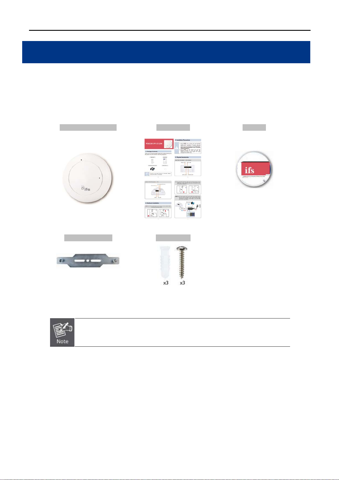
1.1 Package Contents
Thank you for choosing IFS WMC303-1W-1T-1200. Before installing the AP, please verify the contents inside the
package box.
WMC303-1W-1T-1200 Quick Guide CD-ROM
(User Manual included)
If there is any item missing or damaged, please contact the seller immediately.
-1-
Page 16
1.2 Product Description
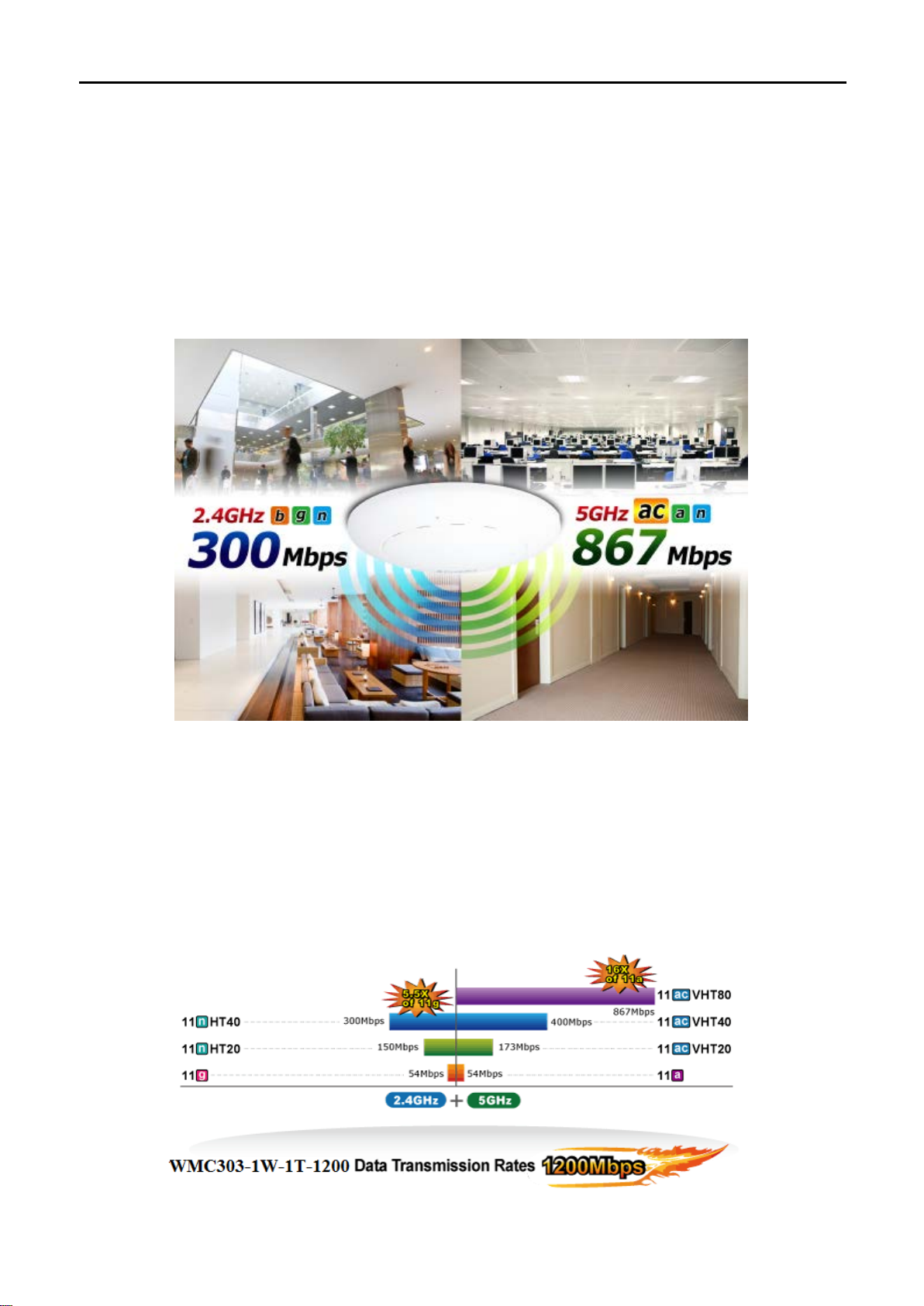
Ceiling Mount Designed for Highly-efficient Wireless Coverage
Featuring attractive flying saucer appearance and ceiling-mount design, the WMC303-1200 can be firmly
installed on the ceiling or the wall conveniently. The ceiling-mount design is smartly integrated into the
environment. Its stream lined body without the protr uding antennas also gives effects of embellishment in the
surroundings. Moreo ver, the WMC303-1200 is compliant w ith the I EEE 802. 3at PoE standar d, so it is eas y and
flexible in client-side installation. It is definitely nice to have this eye-catching access point mount on the ceilings
and walls of villas, hotels, exhibit halls, and other establishments.
Brand-new 11ac Wireless Technology
The WMC303-1200 supports IEEE 802.11a/b/g/n/ac dual band standards with 2T2R MIMO technology;
therefore, it provides the wireless s peed up to 300 +867Mbps, which is 16X faster than the 11a access point at
5GHz frequency and 5. 5X f aster than t he 11g access point at 2. 4GH z frequenc y. Moreover, the WMC303-1200
is equipped with Gigabit Ethernet Port. Compared with the general wireless APs, the WMC303-1200 offers
faster transmiss ion speed for the network applicati ons and less interference t o enhance data throughput. T he
incredible wireless speed makes it ideal for handling multiple HD movie streams, high-resolution on-line games,
stereo music, VoIPs and data streams at the same time stably and smoothly.
11ac Innovations Bring Excellent Data Link Speed
-2-
Page 17
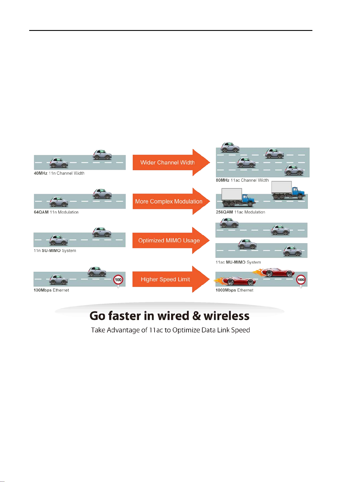
The WMC303-1200 is b uilt-in with high power am plifier and 4 hig hly-sens itive ante nnas whic h provide str onger
signal and excellent coverage even in the wide-ranging or bad en vironment. With adjustable transm it power
option, the administrator can flexibly reduce or increase the output power for various environments, thus
reducing interferenc e to achie ve m aximum perf orm ance. To provide extremely high-speed user exper ience, the
WMC303-1200 adopts IE E E 8 02.11ac technology to e x tend the 802.11n 40MHz channel binding to 8 0MHz and
the implementation of 256-QAM modulation where higher transmitting/receiving rates go up to 867Mbps in
5GHz less interferenc e frequency band. In additi on, the WMC303-1200 is equipped wit h gigabit LAN port to
eliminate the restriction of 100Mbps Fast Ethernet wired connection to let users fully enjoy the high speed
provided by wireless. The IEEE 802.11ac also optimizes MU-MIMO (Multi-User MIMO) m echanism to serve
multiple devices simultaneously.
Full Support of Wireless Security Encryption and Wireless Value-added Features
In aspect of securit y, besides 64/128-b it WEP encryption, the WMC303-1200 is integrated with WPA / WPA2,
WPA-PSK / W PA2-PSK and 802.1x Radius authority to secure and pr otect your wireless LAN. It pr ovides the
wireless MAC filtering and SSID broadcast control to consolidate the wireless network security and prevent
unauthorized wireles s connection. Being an access point, the WMC303-1200 supports the VLAN func tion to
allow multiple SSIDs (10 sets of SSIDs) to access Internal VLAN topology. Moreover, its Wi-Fi Multimedia (WMM)
mechanism provides enhanced QoS over wireless connection for better performance in multimedia transmission
like on-line gaming and video streaming, which are classified as a top priority.
-3-
Page 18
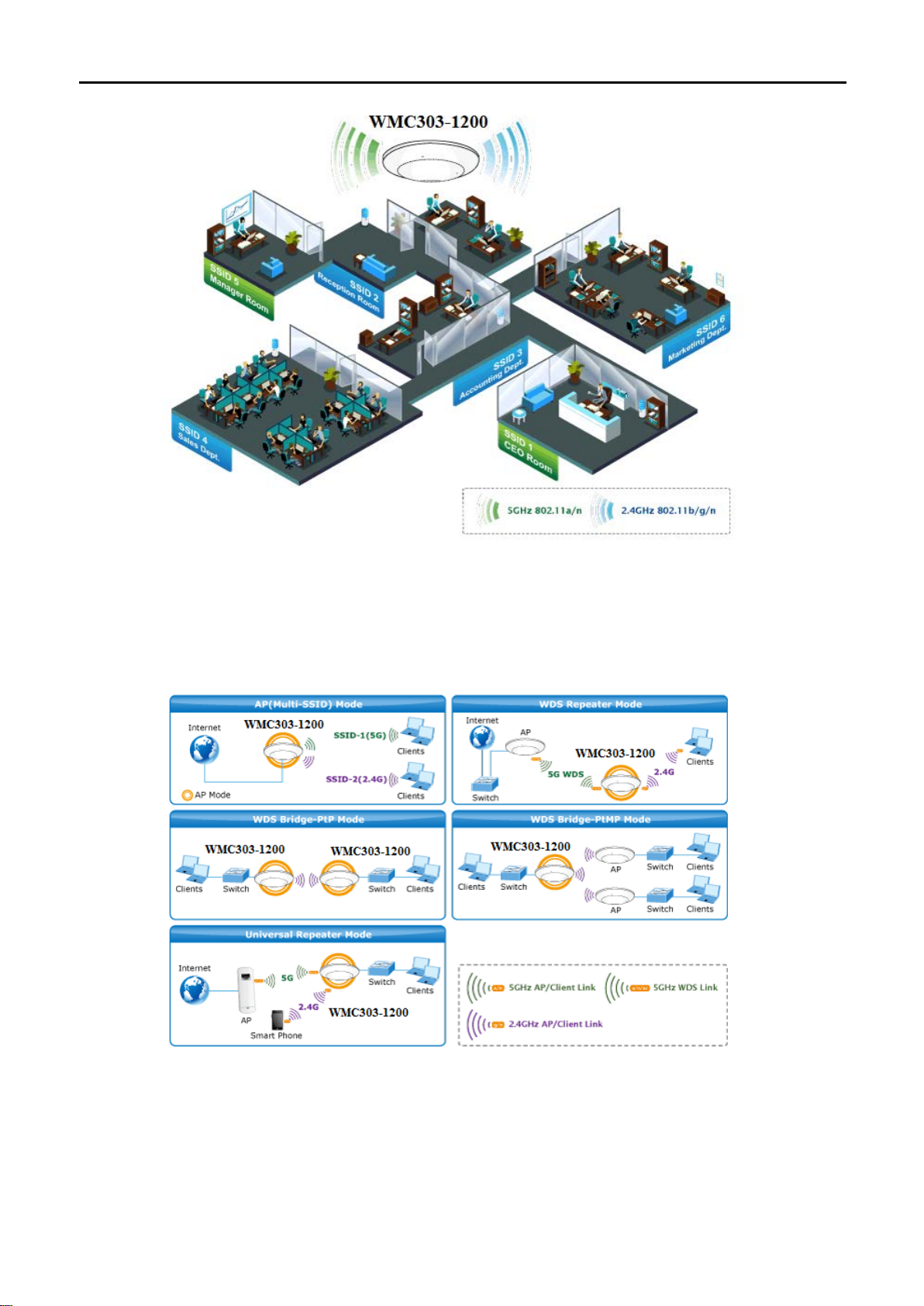
Multiple Operation Modes for Various Applications
The WMC303-1200 supports AP, Client, WDS Bridge, Repeater a nd U niversa l Re peat er m odes, thr ough whic h
it provides more flexibility for users when wireless network is established. Compared with general wireless
access point, the WMC303-1W-1T-1200 offers more powerful and flexible capability for wireless clients.
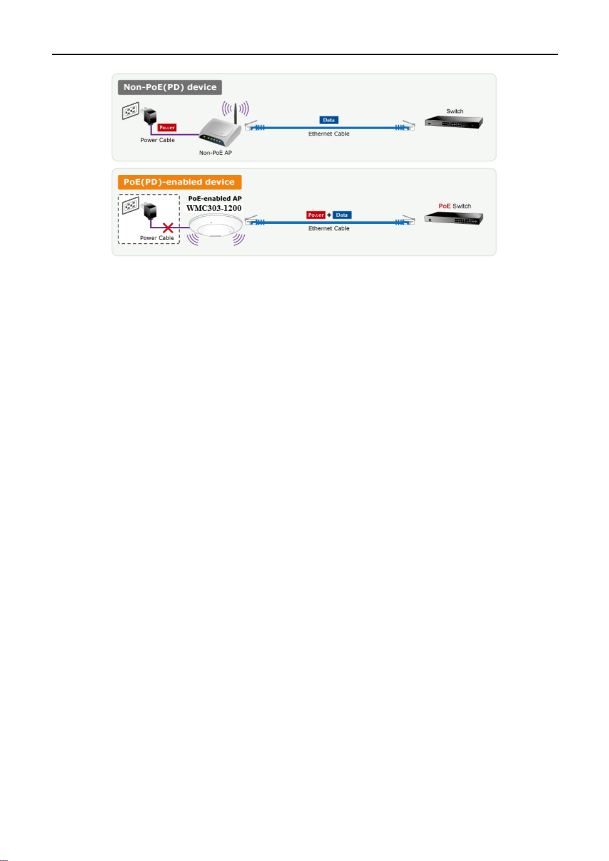
Flexible Deployment with PoE Feature
Compliant with the IEEE 802.3at Power over Ethernet standard, the WMC303-1200 can be powered and
networked by a single UT P cable. It thus reduces the needs of ex tra cables and dedic ated electrical ou tlets on
the wall, ceiling or any other place where it is difficult to reach. The wireless network deployment becomes more
flexible and worry-fr ee fr om the power out let locat io ns .
-4-
Page 19
Easy Installation and Management
With user-friendl y Web UI and step-by-step Quick Setup W izard, the WMC303-1200 is easy to install, even for
users who never experience setting up a wireless network. Furthermore, with SNMP-based management
interface, the WMC303-1200 is convenient to be managed and configured remotely in a small business wireless
network.
-5-
Page 20

1.3 Product Features
Standard C o m p liant Hardware Interface
Complies with IEEE 802.11ac (draft 2.0) and IEEE 802.11a/b/g/n standards
1 x 10/100/1000Base-TX Port with 1-port PoE (PD, Powered Device)
IEEE 802.3at Power over Ethernet design
RF Interface Characteristics
Features 2.4GHz (802.11b/g/n) and 5GHz (802.11a/n/ac) concurrent dual band for more efficiency
of carrying high load traffic
2T2R MIMO technology for enhanced throughput and coverage
Provides multiple adjustable transmit power control
High speed up to 1.2Gbps (300Mbps for 2.4GHz + 867Mbps for 5GHz) wireless data rate
Comprehensive Wireless Advanced Features
Multiple Wireless Modes: AP, Client, WDS PtP/ PtMP, WDS Repeater, Universal Repeater
Supports up to 10 multiple-SSIDs (2.4GHz+5GHz) to allow users to access different networks
through a single AP
Supports VLAN function to limit the clients to access the specific internal network resource
Supports WMM (Wi-Fi Multimedia) and wireless QoS to enhance the efficiency of multimedia
application
Supports IAPP (Inter Access Point Protocol) and wireless roaming to enable clients to roam across
different wireless networks
Supports 5-level Transmitting Power Control to adapt various environments
Supports wireless schedule to automatically enable or disable the wireless function based on
predefined schedule
Secure Network Connection
Advanced security: 64/128-bit WEP, WPA / WPA2, WP A-PSK / WPA2-PSK (TKIP/AES encryption)
and 802.1x Radius Authentication
Supports MAC address filtering
Easy Installation & Management
Flexib le deployment with standard 802.3at PoE/ PD supported
Web-based UI and Quick Setup Wizard for easy configuration
Remote Management allows configuration from a remote site
SNMP-based management interface
System status monitoring includes DHCP Client and System Log
-6-
Page 21
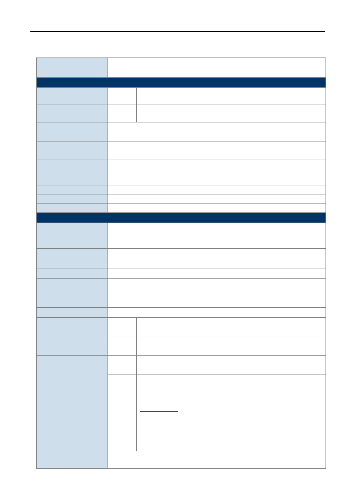
1.4 Product Specifications
1200Mbps 802.11ac Dual Band Ceiling Mount Wireless Access Point
Hardware Specifications
Auto-negotiation and Auto MDI/MDI-X
2 x 5GHz 4dBi PCBA antenna
Press over 7 seconds to reset the device to factory default
Allow LED to turn off via software control
Material
Plastic
Dimensions (Φ x H)
194 x 49 mm
Weight
300 ±5g
Power Requirements
802.3at PoE, 48-56V DC input
Power Consumption
20W (max.)
Mounting
Ceiling Mount
Wireless Interface Specifications
IEEE 802.11b/g/n 2.4GHz
802.11n: 2T2R MIMO
Modulation
DSSS
Band Mode
Europe/ ETSI: 2.412~2.484GHz
Europe/ ETSI: 1~13
5GHz channel list will vary in different countries according to their
802.11n: 20/40MHz
Product
WMC303-1W-1T-1200
Interfaces LAN
Antennas Gain:
Reset button on the top cover
Reset Button
LED Indicators
PWR
IEEE 802.11ac (Draft 2.0) 5GHz
Standard
IEEE 802.11a/n 5GHz
1 x 10/100/1000Base-T RJ45 port
2 x 2.4GHz 2.5dBi PCBA antenna
Antenna Structure
Data Modulation
Frequency Range
Operating Channels
802.11ac: 2T2R MU-MIMO
802.11ac: OFDM (BPSK / QPSK / 16QAM / 64QAM / 256QAM)
802.11a/g/n: OFDM (BPSK / QPSK / 16QAM / 64QAM)
802.11b: DSSS (DBPSK / DQPSK / CCK)
2.4G / 5G concurrent mode
2.4GHz
5GHz
America/ FCC: 2.412~2.462GHz
America/ FCC: 5.180~5.240GHz, 5.725~5.850GHz
Europe/ ETSI: 5.180~5.240GHz
2.4GHz
America/ FCC: 1~11
America/ FCC:
36, 40, 44, 48, 149, 153, 157, 161, 165
5GHz
Europe/ ETSI:
36, 40, 44, 48
regulations.
Channel Width
802.11ac: 20/40/80MHz
-7-
Page 22

802.11ac (VHT80, Nss2-MCS9): Up to 867Mbps
135/121.5/108/81/54/40.5/27/13.5Mbps (dynamic)
65/58.5/52/39/26/19.5/13/6.5Mbps (dynamic)
802.11g: 54/48/36/24/18/12/9/6Mbps (dynamic)
802.11b: 11/5.5/2/1Mbps (dynamic)
The estimated transmission distance is based on the theory. The actual
distance will vary in different environments.
802.11a: 22dBm
802.11a: -93 @ 6Mbps, -75dBm @ 54Mbps
802.11b (11Mbps): -88dBm @10% PER
AP (Access Point)
Provides wireless LAN ACL (Access Control List) filtering
Wireless MAC address filtering
802.11ac (VHT20, Nss2-MCS8): Up to 173.3Mbps
802.11ac (VHT40, Nss2-MCS9): Up to 400Mbps
Data Transmission
Rates
Transmission Distance
Max. RF Power
Receive Sensitivity
802.11n (HT40): 270/243/216/162/108/81/54/27Mbps
802.11n (HT20): 130/117/104/78/52/39/26/13Mbps
802.11ac (draft): up to 30m
802.11n: up to 70m
802.11g: up to 30m
5GHz:
802.11ac (VHT20): 22dBm
802.11ac (VHT40): 22dBm
802.11ac (VHT80): 22dBm
802.11n (HT20): 22dBm
802.11n (HT40): 22dBm
2.4GHz:
802.11n: 17 ±2.5dBm
802.11b/g: 20 ±2.5dBm
5GHz:
802.11ac (VHT20): -91dBm @ Nss1-MCS0, -64dBm @ Nss2-MCS8
802.11ac (VHT40): -89dBm @ Nss1-MCS0, -59dBm @ Nss2-MCS9
802.11ac (VHT80): -86dBm @ Nss1-MCS0, -56dBm @ Nss2-MCS9
802.11n (HT20): -92dBm @ MCS0, -71dBm @ MCS7
802.11n (HT40): -89dBm @ MCS0, -66dBm @ MCS15
2.4GHz:
802.11n 20MHz (MCS7): -69dBm @10% PER
802.11n 40MHz (MCS15): -66dBm @10% PER
802.11g (54Mbps): -74dBm @10% PER
Software Features
Universal Repeater
(AP+Client)
Wireless Mode
Repeater
(WDS+AP)
WEP (64/128-bit) encryption security
Encryption Security
WPA / WPA2 ( TKIP/AES)
WPA-PSK / WPA2-PSK (TKIP/AES)
Wireless Securit y
-8-
WDS PTP (Point to Point)
WDS PTMP (Point to Multipoint)
Client
Page 23

Supports WPS (Wi-Fi Protected Setup)
Enable/ Disable SSID Broadcast
Wireless Advanced
WMM (Wi-Fi Multimedia): 802.11e Wireless QoS
Multiple SSID: up to 5 at 2.4GHz and 5GHz, respectively
Wireless Isolation: Enables to isolate each connected wireless client from
communicating with each other
IAPP (Inter Access Point Protocol): 802.11f Wireless Roaming
Provides Wireless S ta tisti cs
5GHz Wireless: 32
Built-in DHCP server supporting static IP address distributing
Supports UPnP
Supports 802.1d Spanning Tree
Supports 802.1Q VLAN
Web-based (HTTP) management interface
SNTP time synchronize
Easy firmware upgrade
Supports Scheduling Reboot
Standards Conformance
IEEE 802.3x Flow Control
Environment & Certification
Max. Clients
LAN
Wire: 253
2.4GHz Wireless: 32
System Management
IEEE Standards
Other Protocols and
Standards
Temperature
Humidity
IEEE 802.11ac (Draft 2.0, 2T2R, up to 867Mbps)
IEEE 802.11n (2T2R, up to 300Mbps)
IEEE 802.11g
IEEE 802.11b
IEEE 802.11i
IEEE 802.3 10Base-T
IEEE 802.3u 100Base-TX
IEEE 802.3ab 1000Base-T
CSMA/CA, CSMA/CD, TCP/IP, DHCP, ICMP, SNTP
Operating: 0 ~ 50 degrees C
Storage: -40 ~ 70 degrees C
Operating: 10 ~ 90% (non-condensing)
Storage: 5 ~ 90% (non-condensing)
Regulatory
FCC Part 15B & 15C, IC, RoHS
-9-
Page 24
Chapter 2. Hardware Installation
Please follow the instructions below to connect WMC303-1W-1T-1200 to the existing network devices and your computers.
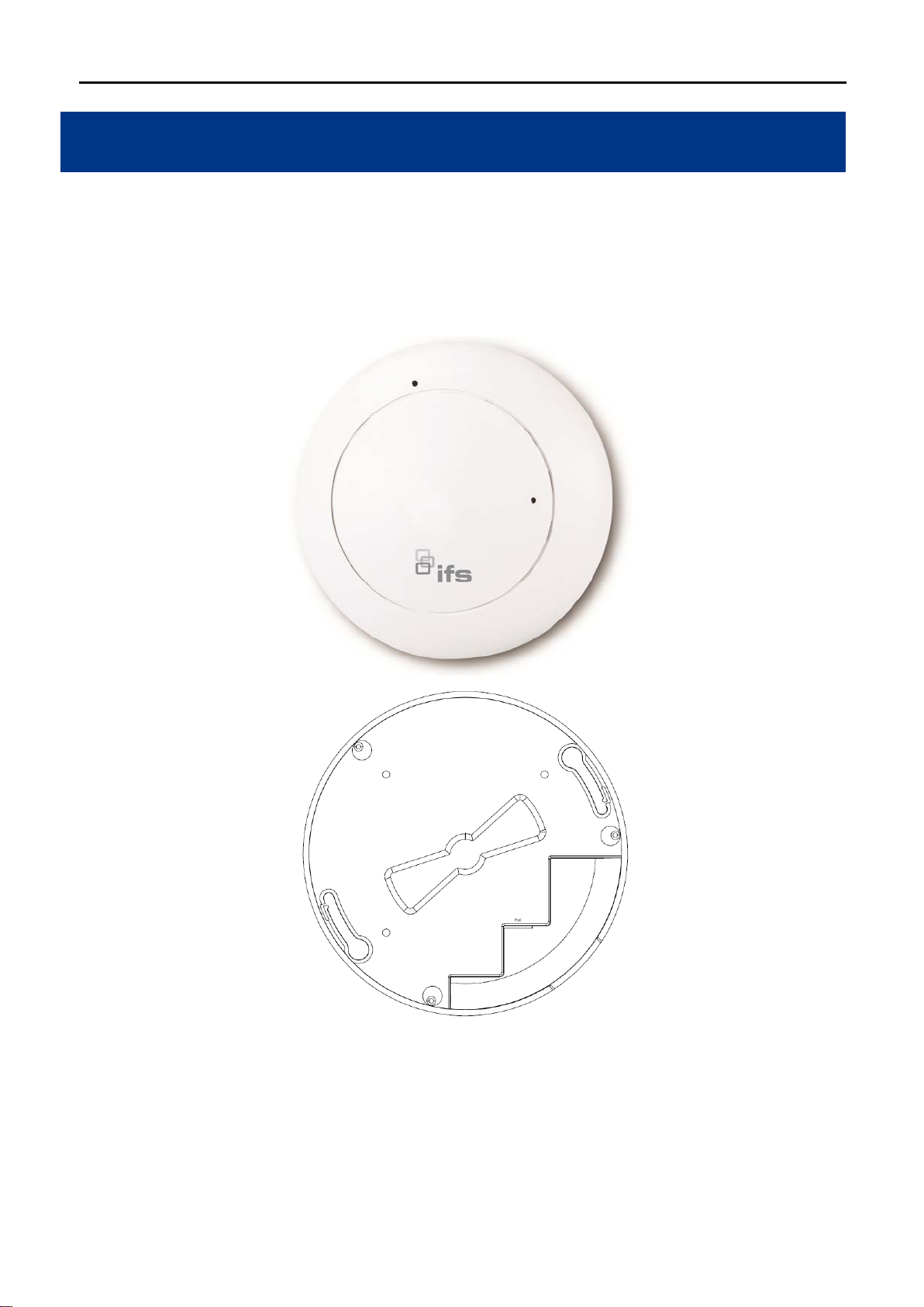
2.1 Product Outlook
Dimensions: 194 x 49 mm (Φ x H)
Drawing :
Figure 2-1 WMC303-1W-1T-1200 Product Drawing
-10-
Page 25
Object
Description
Object
Description
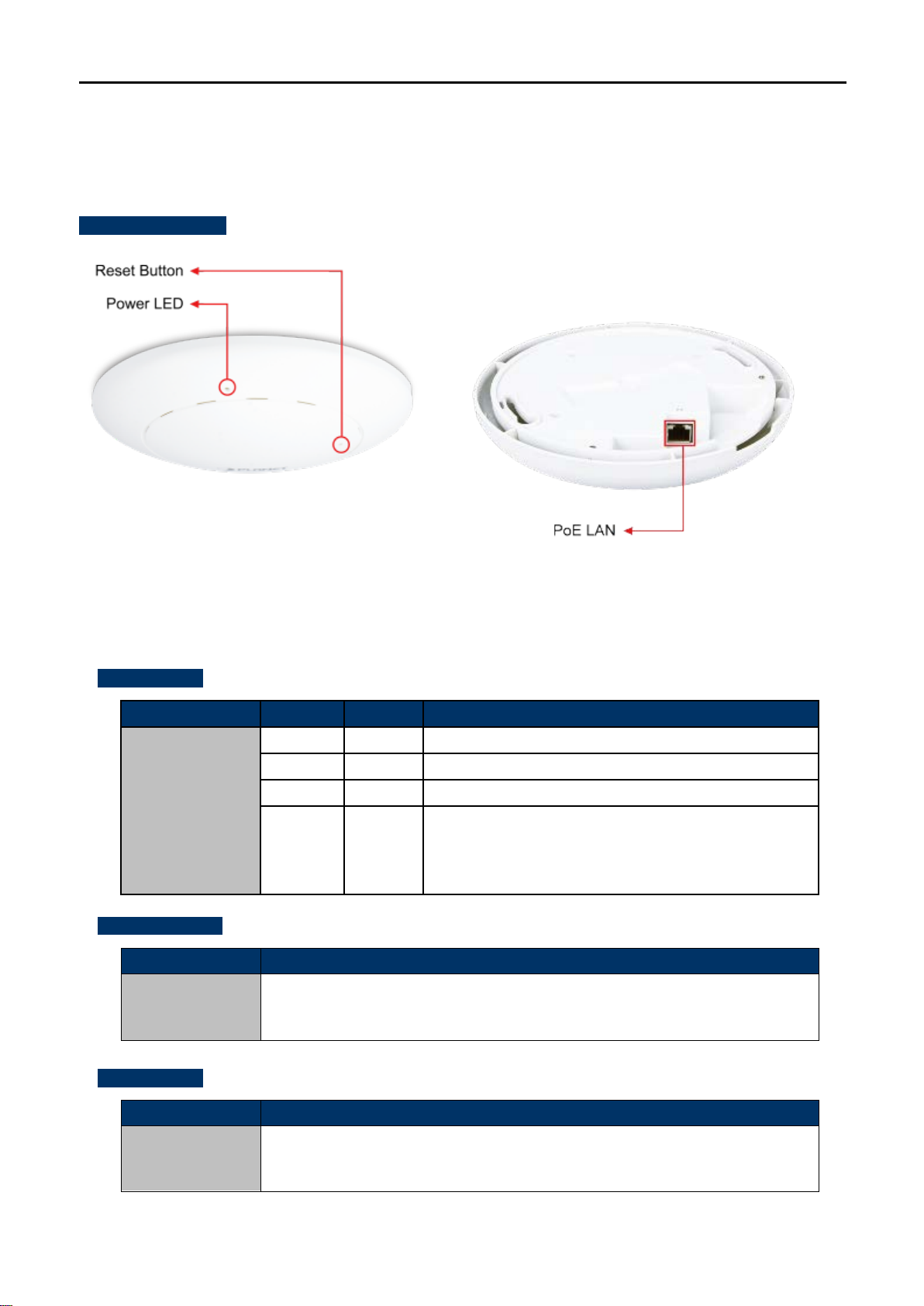
2.1.1 Panel Layout
The front and rear panel prov ide a simple interface m onitor ing the AP. Figure 2-2 shows the hardware inter fac e
of the WMC303-1W-1T-1200.
Hardware Interface
2.1.2 Hardware Description
LED definition
LED COLOR STATUS FUNCTION
PWR
Button definition
Reset
Figure 2-2 WMC303-1W-1T-1200 Panel Layout
Green
Green
Orange
Orange
On Device power on
Off Device power off (control by S/W)
On System initializing, turned it off when system completed
Detect and identify the LED (control by S/W)
Blinking
1) Position LED on: LED blinks continuously.
2) Position LED off: the LED is off.
To restore to the factory default setting, press and hold the Reset Button over 7
seconds, and then release it.
Port definition
PoE Port
(802.3at PoE)
10/100/1000Mbps RJ-45 port , Auto MDI/ MDI-X
Connect PoE port to the IEEE 802.3at PSE to power on the device.
-11-
Page 26
1. The
2.
Chapter 3. Connecting to the AP
3.1 System Requirements
Broadband Internet Access Service (Cable/xDSL/Ethernet connection)
One IEEE 802.3at PoE switch (supply power to the WMC303-1200)
PCs with a working Ethernet Adapter and an Ethernet cable with RJ-45 connectors
PCs running Windows 98/ME, NT4.0, 2000/XP, Windows Vista / Win 7, MAC OS 9 or later, Linux,
UNIX or other platforms compatible with TCP/IP protocols
AP in the following instructions refers to IFS WMC303-1200.
It is recommended to use Internet Explorer 7.0 or above to access the AP.
3.2 Installing the AP
Before installing the AP, make sure your PoE switch is connected to the Internet th rough the broa dband ser vice
successfully at this moment. If there is an y problem , please cont act your local ISP. After that, please ins tall the
AP according to the following steps. Don't forget to pull out the power plug and keep your hands dry.
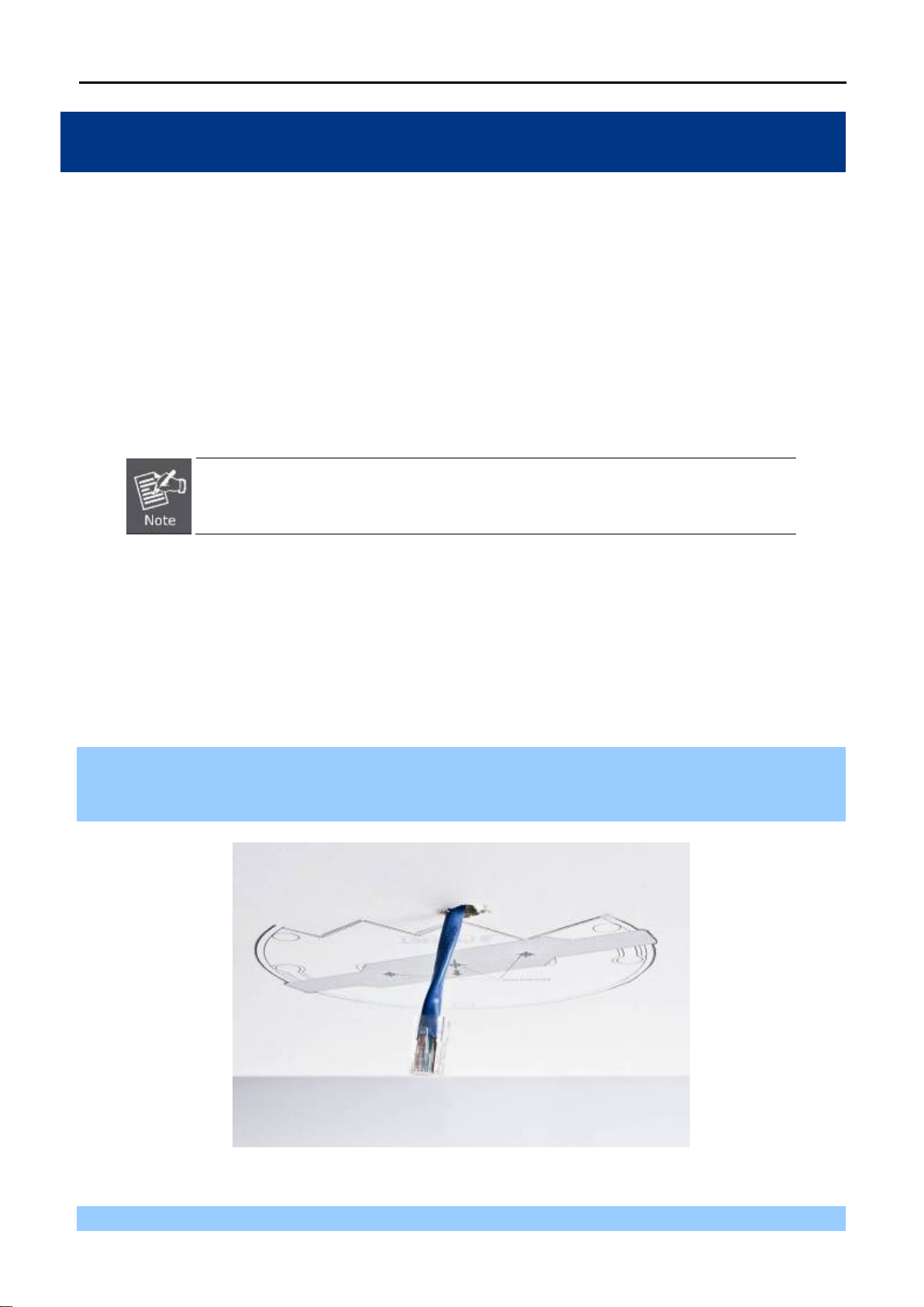
Step 1. Drill the outlet hole indicated on the mounting label and stick the given mounting label to the installation
location to let the Ether net cable penetrat e t he out let h ole. T hen, dr ill the m ount ing ho les as indic ated
on the label.
Figure 3-1 WMC303-1200 Installation Dia gram 1
Step 2. Take the mounting bracket, put i t on the targe t place by a ligning the holes and f ix it with t he supplied
-12-
Page 27
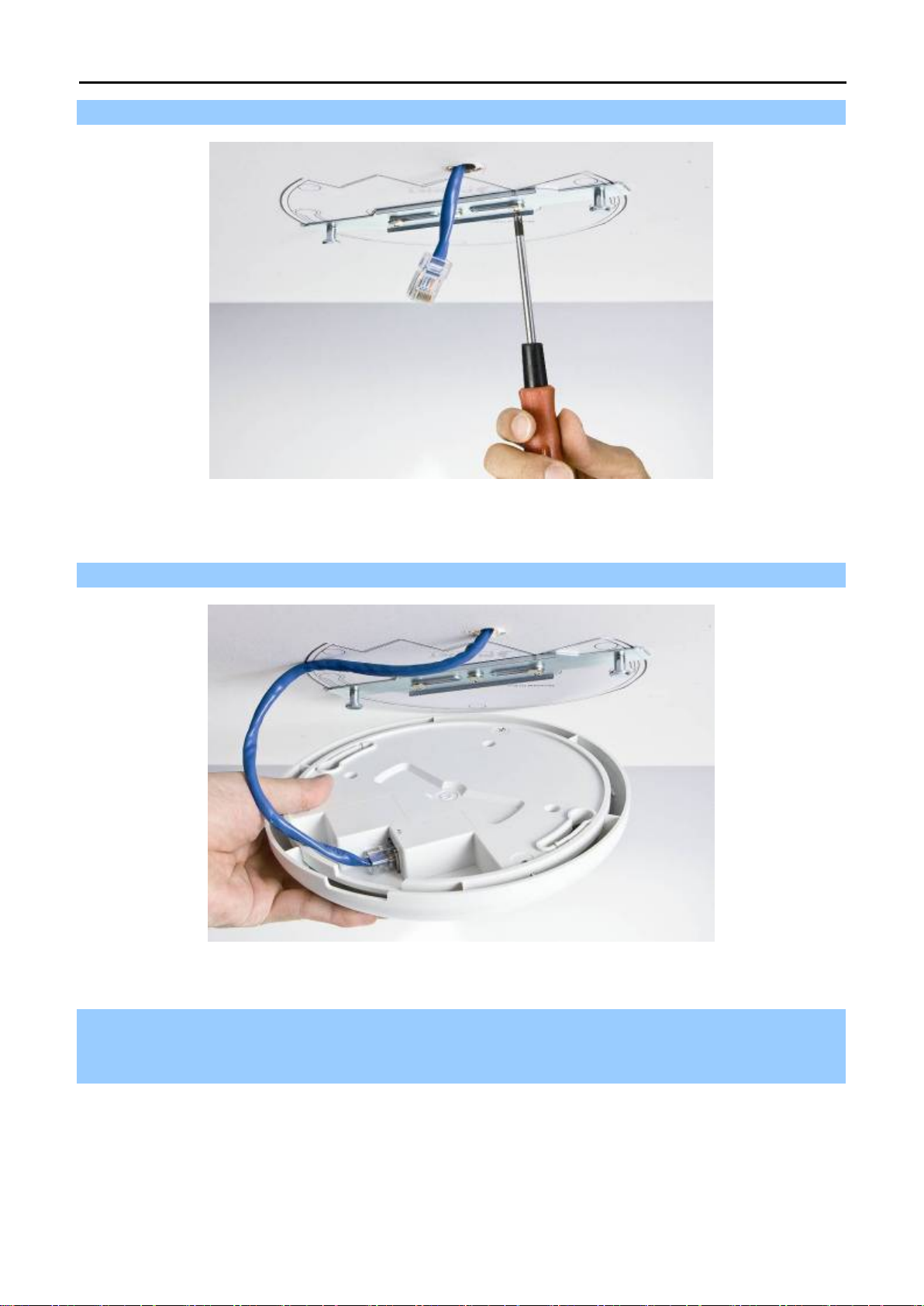
screws. ※ IEEE 802.3at PoE switch is required.
Figure 3-2 WMC303-1200 Installation Dia gram 2
Step 3. Plug the RJ-45 Ethernet cable into the PoE port of the WMC303-1W-1T-1200.
Figure 3-3 WMC303-1200 Installation Dia gram 3
Step 4. Load the device into the mounting bracket, and be sur e the device is mated with t wo fixed screws.
Then, rotate the device clockwise to lock it in position.
-13-
Page 28
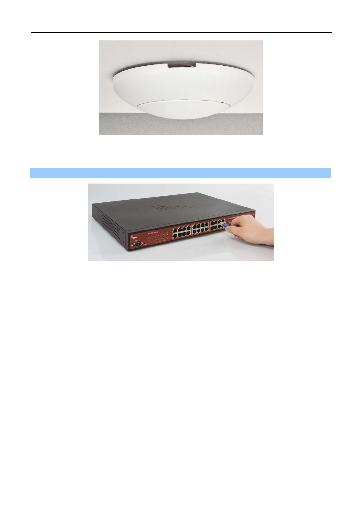
Figure 3-4 WMC303-1200 Installation Dia gram 4
Step 5. Plug the other end of the Ethernet cable into the PoE switch.
Figure 3-5 WMC303-1200 Installation Dia gram 4
-14-
Page 29

time
Chapter 4. Quick Installation Guide
This chapter will show you how to configure the basic functions of your AP within minutes.
A computer with wired Ethernet connection to th e Wireless AP is required f or the firstconfiguration.
4.1 Manual Network Setup - TCP/IP Configuration
The default IP address of the WMC303-1200 is 192.168.0.253. And the default Subne t Mask is 255.255.25 5.0.
These values can be changed as you want. In this guide, we use all the default values for description.
Connect the WMC303-1200 with your PC by an Ethernet cable plugging in LAN port on one side and in LAN port
of PC on the other side. Please power on the WMC303-1200 by PoE switch through the PoE port.
In the following sections, we’ll introduce how to install and configure the TCP/IP correctly in Windows 7. And the
procedures in other operati ng s ystem s ar e similar. First, make sure your Et herne t Ada pter is working, and refer
to the Ethernet adapter manual if needed.
4.1.1 Configuring the IP Address Manually
Summary:
Set up the TCP/IP Protocol for your PC.
Configure the network param eters. The IP address is 192.168.1.xxx (if the default IP address of the
WMC303-1200 is 192.168.0.253, and the DSL router i s 192.168.0.253, the "xxx" can be c onfigured t o
any number from 1 to 252), Subnet Mask is 255.255.255.0.
1 Select Use the following IP address radio button, and then configure the IP address of the PC.
2 For example, as the default IP address of the WMC303-1200 is 192.168.0.253 and the DSL router is
192.168.0.253, you may choose from 192.168.0.1 to 192.168.0.252.
-15-
Page 30
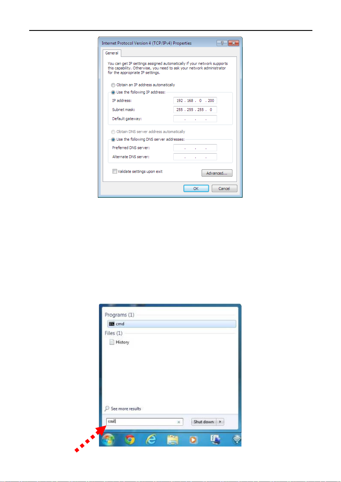
Figure 4-1 TCP/IP Setting
Now click OK to save your settings.
Now, you can run the Ping command in th e command prompt to verify the network connection bet ween your
PC and the AP. The following example is in Windows 7 OS. Please follow the steps below:
1. Click on Start > Run.
2. Type “cmd” in the Search box.
Figure 4-2 Windows Start Menu
-16-
Page 31

3. Open a command prompt, type ping 192.168.0.253 and then press Enter.
If the result displayed is similar to Figure 4-3, it means the connection b etween your PC a nd the AP
has been established well.
Figure 4-3 Successful result of Ping command
If the result displayed is similar to Figure 4-4, it m eans the connection between your PC and the AP
has failed.
Figure 4-4 Failed Result of Ping Command
If the address is 0.0. 0.0, check your adapter installation, sec urity settings, an d the settings on your AP. S ome
firewall software programs may block a DHCP request on newly installed adapters.
-17-
Page 32

4.2 Starting Setup in the Web UI
It is easy to configure and manage the AP with the web browser.
Step 1. To access the configuration utility, open a web-browser and enter the default IP address
http://192.168.0.253 in the web address field of the browser.
Figure 4-5 Login by default IP address
After a moment, a logi n w indow will ap pear. Enter admin for the User N am e and Passwor d, bot h in lower c as e
letters. Then click the OK button or press the Enter key.
Default IP Address: 192.168.0.100
Default User name: admin
Default Password: admin
If the above screen does not pop up, it may mean that your web-browser has been set to a
proxy. Go to Tools menu>Internet Options>Connections>LAN Settings on the screen that
appears, cancel the Using Proxy checkbox, and click OK to finish it.
Figure 4-6 Login Window
-18-
Page 33

Chapter 5. Configuring the AP
This chapter delivers a detailed presentation of AP’s functionalities and f eatures under 6 m ain menus below,
allowing you to manage the AP with ease.
Figure 5-1 Main Menu
During operation, if you are not clear about a certain feature, you can refer to the “Help” section in the right side
of the screen to read all related helpful info.
5.1 Setup Wizard
The Setup Wizard will guide the user to configure the WMC303-1200 easily and quickly. Select the Setup Wizard
on the left side of the sc reen and by click ing on Next on the Set up Wizard screen sho wn below, you will then
name your WMC303-1200 and set up its security.
Figure 5-2 Setup Wizard
-19-
Page 34

Step 1: LAN Interface Setup
Figure 5-3 LAN Interface SetupTopology
Figure 5-4 Wizard – LAN Interface Setup
The page includes the following fields:
Object Description
IP Address
Subnet Mask
Default Gateway
Displays the current IP address of the AP. (Default = 192.168.0.100)
Displays LAN mask of the AP. (Default = 255.255.255.0)
IP address of the associated router. (Def ault = 192.168.0.253)
Step 2: Time Zone Setting
Figure 5-5 Time Zone Setup Topology
-20-
Page 35

Figure 5-6 Wizard – Time Zone Setup
The page includes the following fields:
Object Description
Enable NTP client update
Automatically adjust
Daylight Saving
Time Zone Select
NTP Server
Enable NTP client update
Check this box to connect NTP Server and synchronize internet time.
Check this box and system will adjust the daylight saving
automatically.
Select the Time Zone from the drop-down menu.
Select the NTP Server from the drop-down menu.
Check this box to connect NTP Server and synchronize internet time.
Step 3: Wireless 5GHz Basic Settings
Figure 5-7 Wizard – Wireless 5GHz Basic Settings
The page includes the following fields:
-21-
Page 36

SSID
Key length
Key Setting
Object Description
Band
Supports 802.11a, 802.11n, 802.11ac and m ixed. Please choose its band
according to your clients.
Mode
Supports AP, Client, WDS and AP+WDS mode.
Service Set Identifier identifies your wirel es s networ k .
Channel Width
Select 80MHz if you use 802.11ac; select 40MHz if you use 802.11n;
otherwise, 20MHz for the 802.11a mode.
Control Sideband
It is only valid when you choose channel width 40MHz.
Channel Number
Indicates the channel setting for the AP.
Step 4: Wireless 5GHz Security Settings
Secure your wireless net work by turning on the WPA or WEP security feature on t h e rout er. For this section you
can set WEP and WPA-PSK security mode.
Figure 5-8 Wizard – Wireless 5GHz Security Setup
Encryption: WEP
The following picture shows how to set the WEP security.
Figure 5-9 5GHz Wireless Security Setup – WEP Setting
The page includes the following fields:
Object Description
WEP supports 64-bit or 128-bit security key.
Key Format
User can enter key in ASCII or Hex format.
Enter the key whose format is limited by the Key format, ASCII or Hex.
-22-
Page 37

Encryption: WPA -PSK
The following picture s hows how to set up WPA-PSK security. You can select W PA ( T K I P ) , WPA2 ( AES) and
Mixed mode.
Figure 5-10 5GHz Wireless Security Setup – WPA Setting
The page includes the following fields:
Object Description
Pre-Shared Key Format
Pre-Shared Key
Specify the format of the key, pass phrase or hex.
Enter the key whose format is limited by the key format.
Step 5: Wireless 2.4GHz Basic Settings
Figure 5-11 Wizard – Wireless 2.4GHz Basic Settings
-23-
Page 38

The page includes the following fields:
Object Description
Band
Supports 802.11b, 802.11g, 802.11n and mixed. Please choose its band
according to your clients.
Mode
SSID
Channel Width
Control Sideband
Channel Number
Supports AP, Client, WDS and AP+WDS mode.
Service Set Identifier, it identifies your wireless network.
Select 40MHz if you use 802.11n, otherwise 20MHz for the 802.11b/g mode.
It is only valid when you choose channel width 40MHz.
Indicates the channel setting for the AP.
Step 6: Wireless 2.4GHz Security Settings
Secure your wireless net work by turning on the WPA or WEP security feature on the router. For this section you
can set WEP and WPA-PSK security mode.
Figure 5-12 Wizard – Wireless 2.4GHz Security Setup
Encryption: WEP
The following picture shows how to set the WEP security.
Figure 5-13 2.4GHz Wireless Security Setup – WEP Setting
-24-
Page 39

Key Length
Key Setting
The page includes the following fields:
Object Description
WEP supports 64-bit or 128-bit security key.
Key Format
User can enter key in ASCII or Hex format.
Enter the key whose format is limited by the Key format, ASCII or Hex.
Encryption: WPA -PSK
The following picture shows how to set WPA-PSK security. You can select W PA (T KIP), WPA2 (AES) and
Mixed mode.
Figure 5-14 2.4GHz Wireless Security Setup – WPA Setting
The page includes the following fields:
Object Description
Pre-Shared Key Format
Pre-Shared Key
Specify the format of the key, pass phrase or hex.
Enter the key whose format is limited by the key format.
Click the Finished button to make your wireless configuration to take effect and finish the Setup Wizard.
-25-
Page 40

Figure 5-15 Setup Wizard - Finished
After rebooting, please check whether you can access the Internet or not on the “Status” page.
-26-
Page 41

192.168.0.100. You can change it according to your request.
addresses to clients.
range in the field. And you can click the “Show Client” button to show
5.2 TCP / IP Settings
This page is used to configure the parameters for local area network which connects to the LAN port of your AP.
Here you may change the setting for IP address, subnet mask, DHCP, etc.
5.2.1 LAN Settings
On the LAN Settings page, you can configure the IP parameters of the LAN on the screen as shown below.
The page includes the following fields:
Object Description
IP Address The default LAN IP address of the WMC303-1W-1T-1200 is
Subnet Mask Default is 255.255.255.0. You can change it according to your request.
Default Gateway Default is 192.168.0.253. You can change it according to your request.
DHCP You can select a Disabled, Client, and Server. Default is Disabled,
meaning the WMC303-1200 must connect to a router to assign IP
DHCP Client Range For the Server mode, you must enter the DHCP client IP address
Figure 5-16 LAN Setting
-27-
Page 42

addresses anytime when they request IP addresses.
the LAN.
the Active DHCP Client Table.
Static DHCP Click the “Set Static DHCP” button and you can reserve some IP
addresses for those network devices with the specified MAC
Domain Name Default is IFS.
802.1d Spanning Tree You can enable or disable the Spanning Tree function.
Clone MAC Address You can input an MAC address here for using clone function.
UPnP Enable You can enable or disable the UPnP function.
The UPnP feature allows the devices, such as Internet computers, to
access the local host resources or devices as needed. UPnP devices
can be automatically discovered by the UPnP service application on
If you change the IP address of LAN, you must use the new IP address to login the
AP.
When the IP address of the WMC303-1200 is changed, the clients on the network
often need to wait for a while or even reboot before the y can access the n ew IP
address. For an immediate access to the AP, please flush the netbios cache on the
client computer by running the “nbtstat –r” command before using the device
name of the WMC303-1200 to access its Web Management page.
-28-
Page 43

5.3 WLAN1 (5GHz)
The wireless menu of WLAN1 (5GHz) contains submenus of the settings about wireless network. Please refer to
the following sections for the details.
Figure 5-17 5GHz Wireless Main Menu
5.3.1 Basic Settings
Choose menu “WLAN1 (5GHz) Basic Settings” and you can configure the 5GHz basic settings for the
wireless network on this page. After the configuration is done, pleas e click the “ Apply Changes ” button to save
the settings.
First of all, the wireless AP supports multiple wireless modes for different network applications, which include:
AP
Multiple SSIDs
Univ ersal Repeater
Client
WDS
AP+WDS
It is so easy to com bine th e WMC303-1W-1T-1200 with the existing wire d networ k. The WMC303-1W-1T-1200
definitely provides a total network solution for the home and the SOHO users.
-29-
Page 44

AP
Standard Access Point
Figure 5-18 5GHz Wireless Basic Settings of AP
-30-
Page 45

Disable Wireless LAN
disabling “Broadcast SSID” can provide better
The page includes the following fields:
Object Description
Check the box to disable the wireless function.
Interface
Band Select the desired m ode. Default is “5GHz (A+N+AC)”. It is strongly
recommended that you s et the Band to “5GHz (A+N+AC)”, and all of
802.11a, 802.11n, and 802.11ac wireless stations can connect to the
WMC303-1W-1T-1200.
5 GHz (A): 802.11a mode, rate is up to 54Mbps
5 GHz (N): 802.11n mode, rate is up to 300Mbps
5 GHz (AC): 802.11n mode, rate is up to 867Mbps(2T2R)
5 GHz (A+N): 802.11a/n mode, rate is up to 300Mbps
5 GHz (N+AC): 802.11n/ac mode, rate is up to 300Mbps or
867Mbps
5 GHz (A+N+AC): 802.11a/n/ac mode, rate is up to 54Mbps,
300Mbps, or 867Mbps
Mode
There are four kinds of wireless mode selections:
AP
Client
WDS
AP+WDS
If you select WDS or AP+WDS, please click “WDS Settings” submenu
for the related configuration. Furthermore, click the “Multiple AP”
button to enable multiple SSID functions.
SSID
The ID of the wireless network. User can access the wireless network
through it only. However, if you switch to Client Mode, this field
becomes the SSID of the AP you want to connect with.
Default: IFS AP 5G
Channel Width You can select 20MHz, 40MHz or 80MHz.
Channel Number
You can select the operating frequency of wireless network.
Default: 40
Broadcast SSID
If you enable “Broadc ast SSID”, every wire less station located within
the coverage of the AP can discover its signal easily. If you are building
a public wireless network, enabling this feature is recommended. In
private network,
wireless network security.
Data Rate
Default is “Enabled”.
Set the wireless data transfer rate to a certain value. Since most of
wireless devices will negotiate with eac h other and p ick a proper data
-31-
Page 46

” button to show the status table of
transfer rate autom atically, it’s not necessary to change this value
unless you know what will happen after modification.
Default is “Auto”.
Associated Clients
Click the “Show Active Clients
active wireless clients.
Enable Universal
Repeater Mode
(Acting as AP and client
simultaneously)
Universal Repeater is a tec hnolog y used to exten d wir eless cov erag e.
To enable Universal Repeater Mode, check the box and enter the
SSID you want to broadcast in the field below. Then please click
“Security” submenu for the related settings of the AP you want to
connect with.
Multiple-SSID
Enable multiple-SSI D ca n br oadcast m ultiple WLAN SSID's usi ng v irtual interf aces . You can have different
encryption settings for each WLAN and you can restrict what they have access to.
Choose menu “WLAN1 (5GHz) → Basic Settings → Mult iple AP” to configu re the device as a general
wireless access point with m ultiple SSIDs .
Figure 5-19 5GHz Wireless Basic Settings – Multiple AP
The device supports up to four multiple Service Set Identifiers. You can back to the B asic Sett ing s page to
set the Primary SSID. The SSID’s factory default setting is IFS 5G VAP1~4 (Multiple-SSID 1~4). The SSID
can be easily change d to connect to an ex isting wireless net work or to establish a new wireless net work.
-32-
Page 47

When the information for the new SSID is finished, click the Apply Changes button to let your changes take
effect.
Figure 5-20 5GHz Multiple-SSID
Once you have applied a nd saved those settings, you c an then go to the “WLAN1 (5GHz) → Security”
page on the AP to set up security settings for each of the SSIDs.
Universal Repeater
This mode allows the AP with its own BSS to relay data to a root AP to which it is assoc iated with WDS
disabled. The wireless repeater relays signal between its stations and the root AP for greater wireless
range.
1. Example of how to configure Universal Repeater Mode. Please take the following steps:
To configure each wireless parameter, please go to the “WLAN1 (5GHz) → Basic Settings” page.
Step 1. Configure wireless mode to “AP” and then check “Enable Universal Repeater Mode (Acting as AP
and client simultaneously)”. Click “Apply Changes” to take effect.
-33-
Page 48

Figure 5-21 5GHz Universal Repeater-1
Step 2. Go to 5GHz Site Survey page to find the root A P. Select the root AP that you want to repe at the signal
and then click “Next”.
Figure 5-22 5GHz Universal Repeater-2
Step 3. Select the correct encryption method and enter the security key. Then, click “Connect”.
-34-
Page 49

Figure 5-23 5GHz Universal Repeater-3
Step 4. Check “Add to Wireless Profile” and click “Reboot Now”.
Figure 5-24 5GHz Universal Repeater-4
Step 5. Go to “Management-> Status” page to check whether the state of Repeater interface should be
“Connected”.
Figure 5-25 5GHz Universal Repeater-5
-35-
Page 50

Client (Infrastructure)
Combine the W ireles s R outer to t h e Ether net devices such as TV, game player, or HDD and DVD, to make
them be wireless stations.
Figure 5-26 5GHz Wireless Basic Settings – Client
-36-
Page 51

Disable Wireless LAN
The page includes the following fields:
Object Description
Check the box to disable the wireless function.
Interface
Band Select the desired m ode. Default is “5GHz (A+N+AC)”. It is strongly
recommended that you s et the Band to “5GHz (A+N+AC)”, and all of
802.11a, 802.11n, and 802.11ac wireless stations can connect to the
WMC303-1200.
5 GHz (A): 802.11a mode, rate is up to 54Mbps
5 GHz (N): 802.11n mode, rate is up to 300Mbps
5 GHz (AC): 802.11n mode, rate is up to 867Mbps(2T2R)
5 GHz (A+N): 802.11a/n mode, rate is up to 300Mbps
5 GHz (N+AC): 802.11n/ac mode, rate is up to 300Mbps or
867Mbps
5 GHz (A+N+AC): 802.11a/n/ac mode, rate is up to 54Mbps,
300Mbps, or 867Mbps
Mode
There are four kinds of wireless mode selections:
AP
Client
WDS
AP+WDS
If you select WDS or AP+WDS, please click “WDS Settings” submenu
for the related configuration. Furthermore, click the “Multiple AP”
button to enable multiple SSID function.
Network Type In Infrastructure, the wireless LAN serves as a wireless station. And
the user can use the PC e quipped with the WMC303-1200 to access
the wireless net work via other access points. In Ad hoc, the wireless
LAN will use the Ad-hoc mode to operate.
Default is “Infrastructure”.
Note: Only while the wireless mode is set to “Client”, then the
Network Type can be configured.
SSID
The ID of the wireless network. User can access the wireless network
via its ID. However, if you switch to Client mode, this field becomes the
SSID of the AP you want to connect with.
Default: WMC303 5G
Broadcast SSID
If you enable “Broadc ast SSID”, every wire less station located within
the coverage of the WMC303-1200 can discover its signal easily. If you
are building a public wireless network, enabling this feature is
recommended. In private network, disabling “Broadcast SSID” can
provide better wireless network security.
-37-
Page 52

Default is “Enabled”.
Data Rate
Set the wireless data transfer rate to a certain value. Since most of
wireless devices will negotiate with eac h other and p ick a proper data
transfer rate automatically, it’s not necessary to change this value
unless you know what will happen after modification.
Default is “Auto”.
Enable Mac Clone
Enable Mac Clone.
(Single Ethernet Client)
Example of how to configure Client Mode. Please take the following steps:
To configure each wireless parameter, please go to the “WLAN1 (5GHz) → Basic Settings” page.
Step 1. Go to “WLAN1 (5GHz) → Site Su rv ey” page and click “Site Survey” button.
Figure 5-27 Client – Survey
Step 2. Choose the root AP from the list. If the root AP is not listed in the table, re-c lick “ Site Surv e y” t o updat e
the list.
-38-
Page 53

Figure 5-28 Client – AP List
Step 3. Enter the Security Key of the root AP and then click “Connect”.
Figure 5-29 Client – Security
Step 4. Wait until the connection established. Check the “Add to Wireless Profile” option and then reboot it.
-39-
Page 54

Figure 5-30 Client – Status
WDS
Connect this Wireless AP with up to 8 WDS-capable wireless APs to expand the scope of network.
-40-
Page 55

Disable Wireless LAN
Figure 5-31 5GHz Wireless Basic Settings – WDS
The page includes the following fields:
Object Description
Check the box to disable the wireless function.
Interface
Band Select the desired m ode. Default is “5GHz (A+N+AC)”. It is strongly
recommended that you s et the Band to “5GHz (A+N+AC)”, and all of
802.11a, 802.11n, and 802.11ac wireless stations can connect to the
WMC303-1200.
5 GHz (A): 802.11a mode, rate is up to 54Mbps
5 GHz (N): 802.11n mode, rate is up to 300Mbps
5 GHz (AC): 802.11n mode, rate is up to 867Mbps(2T2R)
5 GHz (A+N): 802.11a/n mode, rate is up to 300Mbps
5 GHz (N+AC): 802.11n/ac mode, rate is up to 300Mbps or
-41-
Page 56

867Mbps
5 GHz (A+N+AC): 802.11a/n/ac mode, rate is up to 54Mbps,
300Mbps, or 867Mbps
Mode
There are four kinds of wireless mode selections:
AP
Client
WDS
AP+WDS
If you select WDS or AP+WDS, please click “WDS Settings” submenu
for the related configuration. Furthermore, click the “Multiple AP”
button to enable multiple SSID function.
Channel Width You can select 20MHz, 40MHz or 80MHz.
Control Sideband You can select Upper or Lower.
Channel Number
Data Rate
You can select the operating frequency of wireless network.
Set the wireless data transfer rate to a certain value. Since most of
wireless devices will negotiate with eac h other and p ick a proper data
transfer rate autom atically, it’s not necessary to change this value
unless you know what will happen after modification.
Default is “Auto”.
-42-
Page 57

AP+ WDS
Connect this wireless AP with up to 8 WDS-capable wireless APs, and connect another AP to provide
service for all wireless stations within its coverage.
Figure 5-32 5GHz Wireless Basic Settings – WDS+AP
-43-
Page 58

The page includes the following fields:
Disable Wireless LAN
d. If your country
our local governm ent agency for
Object Description
Check the box to disable the wireless function.
Interface
Country
Select your region from the pull-down lis t.
This field specifies the reg ion where t he wireles s f unction of th e Router
can be used. It ma y be illegal to use the wirel ess f unction of the R outer
in a region other than one of thos e specif ied in this f ie l
or region is not listed, plea se contact y
assistance.
Band Select the desired m ode. Default is “5GHz (A+N+AC)”. It is strongly
recommended that you s et the band to “5GHz (A+N+AC)”, and all of
802.11a, 802.11n, and 802.11ac wireless stations can connect to the
WMC303-1200.
5 GHz (A): 802.11a mode, rate is up to 54Mbps
5 GHz (N): 802.11n mode, rate is up to 300Mbps
5 GHz (AC): 802.11n mode, rate is up to 867Mbps(2T2R)
5 GHz (A+N): 802.11a/n mode, rate is up to 300Mbps
5 GHz (N+AC): 802.11n/ac mode, rate is up to 300Mbps or
867Mbps
5 GHz (A+N+AC): 802.11a/n/ac mode, rate is up to 54Mbps,
300Mbps, or 867Mbps
Mode
There are four kinds of wireless mode selections:
AP
Client
WDS
AP+WDS
SSID
Channel Width You can select 20MHz, 40MHz or 80MHz.
Control Sideband You can select Upper or Lower.
Channel Number
Broadcast SSID
If you select WDS or AP+WDS, please click “WDS Settings” submenu
for the related configuration. Furthermore, click the “Multiple AP”
button to enable multiple SSID functions.
The ID of the wireless network. User can access the wireless network
via its ID only. However, if you switch to Client Mode, this field
becomes the SSID of the AP you want to connect with.
Default: WMC303 5G
You can select the operating frequency of wireless network.
If you enable “Broadc ast SSID”, every wire less station located within
the coverage of the WMC303-1200 can discover its signal easily. If you
are building a public wireless network, enabling this feature is
-44-
Page 59

” button to show the status table of
recommended. In private network, disabling “Broadcast SSID” can
provide better wireless network security.
Default is “Enabled”.
Data Rate
Set the wireless data transfer rate to a certain value. Since most of
wireless devices will negotiate with eac h other and p ick a proper data
transfer rate autom atically, it’s not necessary to change this value
unless you know what will happen after modification.
Default is “Auto”.
Associated Clients
Click the “Show Active Clients
active wireless clients.
Enable Universal
Repeater Mode
(Acting as AP and client
simultaneously)
Universal Repeater is a tec hnolog y used to exten d wir eless cov erag e.
To enable Universal Repeater mode, check the box and enter the
SSID you want to broadcast in the field below. Then please click
“Security” submenu for the related settings of the AP you want to
connect with.
5.3.2 Advanced Settings
Choose menu “WLAN1 (5GHz) Advanced Settings” and you can configure the 5GH z advanced sett ings f or
the wireless network on this page. After the configuration, please click the “Apply” button to save the settings.
Figure 5-33 Wireless Advanced Settings – 5GHz
The page includes the following fields:
-45-
Page 60

Object
Description
Default is “2346”.
Default is “2347”.
Default is “Enabled”.
Default is “Disabled”.
Default is “Enabled”
Default is “Enabled”
exchange data through the
Default is “Disabled”.
which does not need
Default Setting: "Enabled"
Default Setting: "Enabled"
Fragment Threshold You can specify the m aximum size of pack et during t he fragmentation
of data to be transm itted. If you set th is value too low, it will result in
bad performance.
RTS Threshold When the packet size is s maller than the RTS thres hold, the access
point will not use the RTS/CTS mechanism to send this packet.
Beacon Interval The interval of time that this access point broadcasts a beacon.
Beacon is used to synchronize the wireless network. Default is “100”.
IAPP IAPP (Inter-Access Point Protocol) enabled is recommended as it
describes an optional ext ension to I EEE 802.11 that provides wireless
access-point communications among multivendor systems.
Protection It is recommended to enable the protection mechanism. This
mechanism can decr ease the rate of data col lision between 802.11b
and 802.11g wireless stations. When the protectio n mode is enabled,
the throughput of the AP will be a little lower due to the transmission of
heavy frame traffic.
Aggregation It is a function where the values of multiple rows are grouped together.
Short GI It is used to set t he time that the receiver waits for RF reflections to
settle out before sampling data.
WLAN Partition This feature is also calle d “WLAN isolation” or “Block Relay”. If this is
enabled, wireless clients cannot
WMC303-1200.
STBC Activate Space Time Blocking Code (STBC)
channel statement information (CSI).
LDPC Low-density Parity-check Code is wireless data transmit algorithm.
5.3.3 RF Output Power
Choose menu “WL AN1 (5GHz) RF Output Power” to adjust to different level s of transmitting power f or the
wireless network according to various environments on this page. After the configuration, please click the “Apply
Changes” button to save the settings.
-46-
Page 61

Figure 5-34 RF Output Power – 5GHz
RF Output Power Contr ol provides the flexibility to contr ol the Wi-Fi tr ansmit power to op timize the wireless
range. Wi-Fi power consumption for an Access Point could be reduced to up to 75% from its peak power
consumption for ser ving small to m edium size hom es, while booste d to maximum power for large hom es and
businesses. The WMC303-1200 sup ports output power contro l levels up to 5. You can change the RF out put
power level here in accordance with various environments and signal strength.
5.3.4 Security
Choose menu “WL AN1 (5G Hz) Security” and you can conf igure the settings of wireless security for the
wireless network on this page. After the configuration, please click the “Apply Changes” button to save the
settings.
Figure 5-35 Wireless Security Settings – 5GHz
-47-
Page 62

,
The page includes the following fields:
Object Description
Select SSID
Select the SSID you want to configure the wireless security function, which
includes the root one and the client one.
Encryption Disable:
No security setup for wireless connection.
WEP:
It is based on the IEEE 802.11 standard. And the default setting of
authentication is Automatic, which can select Open System or Shared Key
authentication type automatically based on the wireless station's capa bility
and request. Furthermore, you can select Key Length and enter 10 and 26
Hexadecimal digits (any combination of 0-9, a-f, A-F, zero key is not
promoted) or 5 and 13 ASCII characters in the Encryption Key field.
WPA:
WPA is a medium level encryption and is supported by most wireless devices
and operating systems.
WPA2:
WPA2 is a high level encryption and is supp orted by m ost wireless devices
and operating systems.
WPA / WPA2 / WPA-Mixed:
WPA Mixed Mode allows the use of both WPA and WPA2 at the same time.
Authentication Mode
Enterprise (RADIUS)
When you select the authentication mode based on Enterprise (Radius
Server), please enter the IP Address, Port, and Password of the Radius
Server.
Personal (Pre-Shared Key)
When you select the other authentication mode based on Personal
(Pre-Shared Key), please enter at least 8 ASCII c hara cters (Pas sphrase) or
64 Hexadecimal characters. All of the Cipher Suites support TKIP and AES.
802.1x Authentication
Enable 802.1x authentication function and then please enter the IP Address
Port, and Password of the Radius Server.
5.3.5 Access Control
Choose menu “WLAN1 (5GHz) Access Control” to allow or deny the computer of specified MAC address to
connect with the WMC303-1200 on this page. After the configuration, please click the “Apply Changes” button to
save the settings.
-48-
Page 63

to the
Figure 5-36 Wireless Access Control – 5GHz
The page includes the following fields:
Object Description
Wireless Access
You can choose to set the Allowed-List, Denied-List, or disable this function.
Control Mode
MAC Address
Enter the MAC address you want to allow or deny connection
WMC303-1200 in the field.
Comment
Current Access Control
List
You can make some comment on each MAC address on the list.
You can select some MAC addres s es and click the “D elet e S el ected” b utto n to
delete it.
To deny a PC at the MAC address of 9c:F6:1A:00:00:01 (for example) to connect to your wireless network, do as
follows:
Step 1. Select “Deny” from MAC Address Filter drop-down menu.
Step 2. Enter 9c:F6:1A:00:00:01 in the MAC address box and click “Add”.
Step 3. Click the “OK” but ton to save your set tin gs a nd you can add more MAC address es , if you like, simply
repeat the above steps.
-49-
Page 64

Figure 5-37 Wireless Access Control – Deny
-50-
Page 65

5.3.6 WDS
WDS (Wireless Distribution System) feature can be used to extend your existing 2.4G or 5G wireless network
coverage. Here we present you how to configure such feature in 2.4GHz, which also applies to 5GHz.
Before configuring the WDS Setting page, you have to select the wireless mode to “WDS” on the WLAN1 (5GHz)
-> Basic Settings web page.
-51-
Page 66

Figure 5-38 WDS Mode – 5GHz
Choose menu “WLAN1 (5GHz) WDS Settings” to configure WDS to connect the WMC303-1W-1T-1200 with
another AP on this page. After the configuration, please click the “Apply Changes” button to save the settings.
Figure 5-39 WDS Settings – 5GHz
-52-
Page 67

WDS on this page.
MAC Address
You can enter the MAC address of the AP you want to connect with.
Selected” button to delete it.
on both such
the detail of wireles s security, see
Figure 5-40 WDS – Set Security
The page includes the following fields:
Object Description
Enable WDS Check the box to enable the WDS function. Please select WDS or
AP+WDS in the Mode of Wireless B asic Settings befor e you enable
Data Rate Default is “Auto”.
Comment You can make some comment for each MAC address on the list.
Set Security Click the “Set Security” button to configure the wireless security
parameters of the AP you want to connect via WDS.
Show Statics Click the “Show Statics” button to show the WDS AP.
Current WDS AP List You can select some MAC addres ses of the AP and click the “Delete
WDS feature can onl y be implemented between 2 wireless devices that both support the W DS
feature. Plus, channel, security settings and s ecurity key must be the same
devices.
To encrypt your wireless net work, click “Set Securit y”. For
section 5.3.3. Do remem ber to reboot the d evice after you save your wir eless secur ity settings ;
otherwise, the WDS feature may not function.
-53-
Page 68

5.3.7 Site Survey
Choose menu “WLAN1 (5GHz) Site Survey” to scan the available local AP. If any Access Point is found, you
could choose any one to connect with manually when the Client Mode is enabled.
Figure 5-41 Site Survey – 5GHz
5.3.8 WPS
WPS (Wi-Fi Protected Set up) is designed to ease setup of securit y Wi-Fi networ ks and subs equentl y network
management. This Wireless Router supports WPS features for AP mode, AP+WDS mode,
Infrastructure-Client mode, and the wireless root interface of Universal Repeater mode.
Simply enter a PIN code or press the software PBC button or hardware WPS button (if any) and a secure
wireless connection is established.
PBC: If you find the WPS LED blinking for 2 minutes after you press the h ar d ware WPS button on the
device, it means that PBC encryption method is successfully enabled. And an authentication will
be performed between your router and the WPS/PBC-enabled wireless client device during this
time; if it succeeds, the wireless client d evic e connec ts to your dev ice, and t he W PS L ED tu rns
off. Repeat steps mentioned above if you want to connect more wireles s client devices to the
device.
PIN:To use this option, you must know the PIN code from the wireless client and enter it in
corresponding field on your device while using the same PIN code on client side for such
connection.
-54-
Page 69

The page includes the following fields:
ding configuration
Object Description
Disable WPS
WPS Status
Self-PIN Number
Push Button
Configuration
Client PIN Number
You can check the box to disable the WPS function.
Here you can check if the connection via WPS is established or not.
It is the PIN number of the WMC303-1W-1T-1200 here.
Click the “Start PBC” to activate WPS as well in the client device within
2 minutes.
In addition to the PBC m ethod, you can also use the PIN m ethod to
activate the WPS. Just enter the PIN number of the client device in the
field and click the “Start PIN” button.
The WPS encryption can be implemented only between your Router and another
WPS-capable device.
Example of how to es tab lish wireless connection using WPS. Please take the following steps:
Step 1. Choose menu “WLAN1 (5GHz) WPS” to configure the setting for WPS. After the configuration,
please click the “Apply Changes” button to save the settings.
Step 2. Add a new device.
If the wireless adapter supports Wi-Fi Protected Setup (WPS), you can establish a wireless connection between
wireless adapter and AP using either Push Button Configuration (PBC) method or PIN method.
To build a succes sful con nection b y W PS, you sho uld also do the correspon
of the new device for WPS function.
A. By Push Button Configuration (PBC)
-55-
Page 70

i. Click the “Start PBC” Button on the WPS page of the AP.
Figure 5-42 WPS-PBC – 5GHz-1
Figure 5-43 WPS-PBC – 5GHz-2
ii. Press and hold the WPS Button equipped on the adapter directly for 2 or 3 seconds. Or you can click
the WPS button with the same function in the configuration utility of the adapter. The process must be
finished within 2 minutes.
iii. Wait for a while until the next screen appears. Click OK to complete the WPS configuration.
B. By PIN
If the new device supports Wi-Fi Protected Setup and the PIN method, you can add it to the network by PIN with
the following two methods.
Method One: Enter the PIN of your Wireless adapter into the configuration utility of the AP
i. Enter the PIN code of the wireless adapter in the field behind Client PIN Number in the following
figure. Then click Start PIN.
The PIN code of the adapter is always displayed on the WPS configuration screen.
-56-
Page 71

Figure 5-44 WPS-PIN – 5GHz-1
Figure 5-45 WPS-PIN – 5GHz-2
ii. For the configuration of t he wireless adapter, please choos e the option that you want to enter PIN
into the AP (Enrollee) in the configuration utility of the WPS and click Next until the process finishes.
Method T wo: Enter the PIN of the AP into the configuration utility of your Wireless adapter
i. Click the “Start PBC” Button on the WPS page of the AP. Get the Current PIN code of the AP in WPS
page (each AP has its unique PIN code).
Figure 5-46 WPS-PIN – 5GHz-3
ii. For the configuration of the wireless adapter, please choose the option that you want to enter the PIN
of the AP (Registrar) in the conf iguration utility of the Wireless adapter and e nter it into the field.
Then click Next until the process finishes.
-57-
Page 72

5.3.9 Schedule
Wireless Schedules will enable or disable your wireless access at a set time based on your predefined schedule.
This feature is often used for restricting access to all users ( such as children, employees and guests) during
specific times of the day for parental control or security reasons.
Choose menu “WLAN1 (5 GHz) Schedule” to configure the schedule ru le of enabling wirel ess f unc tion . After
the configuration, please click the “Apply Changes” button to save the settings.
Figure 5-47 Schedule - 5GHz
-58-
Page 73

When setting the Wireless Schedule, it is important to ensure that your System Clock
settings have been configured. If not, your Wireless Schedule will not function correctly.
5.4 WLAN2 (2.4GHz)
The Wireless m enu contains submenus of the settings about wireless network . Please refer to the following
sections for the details.
Figure 5-48 2.4GHz Wireless Main Menu
5.4.1 Basic Settings
Choose menu “WL AN2 (2.4GHz) Basic Setting s” to configur e the 2.4GHz basic setti ngs for the wireless
network on this page. After the configuration is done, please click the “Apply Changes” button to save the
settings.
First of all, the wireless AP supports multiple wireless modes for different network applications, which include:
AP
Multiple SSIDs
Univ ersal Repeater
Client
WDS
AP+WDS
It is so easy to combine the WMC303-1200 with the existing wired network. The WMC303-1200 definitely
provides a total network solution for the home and the SOHO users.
AP
-59-
Page 74

Standard Access Point
Figure 5-49 2.4GHz Wireless Basic Settings – AP
-60-
Page 75

Disable Wireless LAN
The page includes the following fields:
Object Description
Check the box to disable the wireless function.
Interface
Band Select the desired m ode. Default is “2.4GHz (B+G+N)”. It is strongl y
recommended that you set the Band to “2.4GHz (B+G+N)”, and all of
802.11b, 802.11g, and 802.11n wireless stations can connect to the
WMC303-1W-1T-1200.
2.4 GHz (B): 802.11b mode, rate is up to 11Mbps
2.4 GHz (G): 802.11g mode, rate is up to 54Mbps
2.4 GHz (N): 802.11n mode, rate is up to 300Mbps(2T2R)
2.4 GHz (B+G): 802.11b/g mode, rate is up to 11Mbps or 54Mbps
2.4 GHz (G+N): 802.11g/n mode, rate is up to 54Mbps or 300Mbps
2.4 GHz (B+G+N): 802.11b/g/n mode, rate is up to 11Mbps,
54Mbps, or 300Mbps
Mode
There are four kinds of wireless mode selections:
AP
Client
WDS
AP+WDS
If you select WDS or AP+WDS, please click “WDS Settings” submenu
for the related configuration. Furthermore, click the “Multiple AP”
button to enable multiple SSID function.
SSID
The ID of the wireless network. User can access the wireless network
via the ID only. However, if you switch to Client Mode, this field
becomes the SSID of the AP you want to connect with.
Default: WMC303 2G
Channel Width You can select 20MHz, or 40MHz.
Channel Number
You can select the operating frequency of wireless network.
Default: 11
Broadcast SSID
If you enable “Broadc ast SSID”, every wire less station located within
the coverage of the AP can discover its signal easily . If you are building
a public wireless network, enabling this feature is recommended. In
private network, disabling “Broadcast SSID” can provide better
wireless network security.
Data Rate
Default is “Enabled”.
Set the wireless data transfer rate to a certain value. Since most of
wireless devices will negotiate with e ach other and p ick a proper data
transfer rate autom atically, it’s not necessary to change this value
-61-
Page 76

table of
unless you know what will happen after modification.
Default is “Auto”.
Associated Clients
Click the “Show Active Clients” button to show the status
active wireless clients.
Enable Universal
Repeater Mode
(Acting as AP and client
simultaneously)
Universal Repeater is a tec hnolog y used to exten d wir eless cov erag e.
To enable Universal Repeater mode, check the box and enter the
SSID you want to broadcast in the field below. Then please click
“Security” submenu for the related settings of the AP you want to
connect with.
Multiple-SSID
Enable multiple-SSI D ca n br oadcast m ultiple WLAN SSID's usi ng v irtual interf aces . You can have different
encryption settings for each WLAN and you can restrict what they have access to.
Choose menu “WL AN1 (2.4GHz) → Basic Settings → Multiple AP” to conf igure the dev ice as a general
wireless access point with m ultiple SSIDs .
Figure 5-50 2.4GHz Wireless Basic Settings – Multiple AP
The device supports up to four multiple Service Set Identifiers. You can back to the B asic Sett ing s page to
set the Primary SSID. The SSID’s factory default set ting is IFS 2.4G V AP1~4 (Multiple-SSID 1~4). T he
SSID can be easily changed to connect to an existing wireless network or to establish a new wireless
network. When the inform ation for the new SSID is finished, click the Apply Changes button to let your
changes take effect.
-62-
Page 77

Figure 5-51 2.4GHz Multiple-SSID
Once you have applied an d saved those settings , you can then go to the “ WLAN1 (2.4GHz) → Security”
page on the AP to set up security settings for each of the SSIDs.
Universal Repeater
This mode allows the AP with its own BSS to relay data to a root AP to which it is assoc iated with WDS
disabled. The wireless repeater relays signal between its stations and the root AP for greater wireless
range.
2. Example of how to configure Universal Repeater Mode. Please take the following steps:
To configure each wireless parameter, please go to the “WLAN2 (2.4GHz) → Basic Settings” page.
Step 1. Configure wireless mode to “ AP” and then check “En able Universal Repeater M ode (Acting as AP
and client simultaneously)”. Click “Apply Changes” to take effect.
-63-
Page 78

Figure 5-52 2.4GHz Universal Repeater-1
Step 2. Go to 2.4GHz Site Survey page to find the root AP. Select the root AP that you want to repeat the signal,
and then click “Next”.
Figure 5-53 2.4GHz Universal Repeater-2
Step 3. Select the correct encryption method and enter the security key. Then, click “Connect”.
-64-
Page 79

Figure 5-54 2.4GHz Universal Repeater-3
Step 4. Check “Add to Wireless Profile” and click “Reboot Now”.
Figure 5-55 2.4GHz Universal Repeater-4
Step 5. Go to “Management-> Status” page to check whether the state of Repeater interface should be
“Connected”.
Figure 5-56 2.4GHz Universal Repeater-5
Client (Infrastructure)
Combine the Wireless Router to the Ethernet devices such as TV, Game player, or HDD and DVD, to make
them be wireless stations.
-65-
Page 80

Object
Description
Disable Wireless LAN
The page includes the following fields:
Interface
Band Select the desired m ode. Default is “2.4GHz (B+G+N)”. It is strongl y
Figure 5-57 2.4GHz Wireless Basic Settings – Client
Check the box to disable the wireless function.
recommended that you set the Band to “2.4GH z (B+G+N)”, and a ll of
802.11b, 802.11g, and 802.11n wireless stations can connect to the
WMC303-1200.
-66-
Page 81

2.4 GHz (B): 802.11b mode, rate is up to 11Mbps
2.4 GHz (G): 802.11g mode, rate is up to 54Mbps
2.4 GHz (N): 802.11n mode, rate is up to 300Mbps(2T2R)
2.4 GHz (B+G): 802.11b/g mode, rate is up to 11Mbps or 54Mbps
2.4 GHz (G+N): 802.11g/n mode, rate is up to 54Mbps or 300Mbps
2.4 GHz (B+G+N): 802.11b/g/n mode, rate is up to 11Mbps,
54Mbps, or 300Mbps
Mode
There are four kinds of wireless mode selections:
AP
Client
WDS
AP+WDS
If you select WDS or AP+WDS, please click “WDS Settings” submenu
for the related configuration. Furthermore, click the “Multiple AP”
button to enable multiple SSID function.
Network Type In Infrastructure, the wireless LAN serves as a wireless station. And
the user can use the PC e quipped with the WMC303-1200 to access
the wireless net work via other access points. In Ad hoc, the wireless
LAN will use the Ad-hoc mode to operate.
SSID
Broadcast SSID
Data Rate
Default is “Infrastructure”.
Note: only while the wireless mode is set to “Client”, then the Network
Type can be configured.
The ID of the wireless network. User can access the wireless network
via the ID only. However, if you switch to Client Mode, this field
becomes the SSID of the AP you want to connect with.
Default: IFS AP 2G
If you enable “Broadc ast SSID”, every wire less station located within
the coverage of the WMC303-1200 can discover its signal easily. If you
are building a public wireless network, enabling this feature is
recommended. In private network, disabling “Broadcast SSID” can
provide better wireless network security.
Default is “Enabled”.
Set the wireless data transfer rate to a certain value. Since most of
wireless devices will negotiate with eac h other and p ick a proper data
transfer rate autom atically, it’s not necessary to change this value
unless you know what will happen after modification.
Enable Mac Clone
(Single Ethernet Client)
Default is “Auto”.
Enable Mac Clone.
-67-
Page 82

Example of how to configure Client Mode. Please take the following steps:
To configure each wireless parameter, please go to the “WLAN2 (2.4GHz) → Basic Settings” page.
Step 1. Go to “WLAN2 (2.4GHz) → Sit e Su rv ey” page and click “Site Survey” button.
Figure 5-58 Client – Survey
-68-
Page 83

Step 2. Choose the root AP from the list. If the root AP is not listed in the table, re-c lick “ Site Su rve y” to updat e
the list.
Figure 5-59 Client – AP List
-69-
Page 84

Step 3. Enter the Security Key of the root AP and then click “Connect”.
Figure 5-60 Client – Security
Step 4. Wait until the connection established. Check the “Add to Wireless Profile” option and then reboot it.
Figure 5-61 Client – Status
WDS
Connect this Wireless AP with up to 8 WDS-capable wireles s APs to expand the scope of network.
-70-
Page 85

Figure 5-62 2.4GHz Wireless Basic Settings – WDS
-71-
Page 86

The page includes the following fields:
Object Description
Disable Wireless LAN
Check the box to disable the wireless function.
Interface
Band Select the desired m ode. Default is “2.4GHz (B+G+N)”. It is strongl y
recommended that you set the Band to “2.4GHz (B+G+N)”, and all of
802.11b, 802.11g, and 802.11n wireless stations can connect to the
WMC303-1200.
2.4 GHz (B): 802.11b mode, rate is up to 11Mbps
2.4 GHz (G): 802.11g mode, rate is up to 54Mbps
2.4 GHz (N): 802.11n mode, rate is up to 300Mbps(2T2R)
2.4 GHz (B+G): 802.11b/g mode, rate is up to 11Mbps or 54Mbps
2.4 GHz (G+N): 802.11g/n mode, rate is up to 54Mbps or 300Mbps
2.4 GHz (B+G+N): 802.11b/g/n mode, rate is up to 11Mbps,
54Mbps, or 300Mbps
Mode
There are four kinds of wireless mode selections:
AP
Client
WDS
AP+WDS
If you select WDS or AP+WDS, please click “WDS Settings” submenu
for the related configuration. Furthermore, click the “Multiple AP”
button to enable multiple SSID function.
Channel Width You can select 20MHz, or 40MHz
Control Sideband You can select Upper or Lower.
Channel Number
Data Rate
You can select the operating frequency of wireless network.
Set the wireless data transfer rate to a certain value. Since most of
wireless devices will negotiate with eac h other and p ick a proper data
transfer rate autom atically, it’s not necessary to change this value
unless you know what will happen after modification.
Default is “Auto”.
AP+ WDS
Connect this Wireless AP with up to 8 WDS-capable wireless APs, and connect another AP to provide
service for all wireless stations within its coverage.
-72-
Page 87

Disable Wireless LAN
Interface
The page includes the following fields:
Object Description
Country
Figure 5-63 2.4GHz Wireless Basic Settings – WDS+AP
Check the box to disable the wireless function.
Select your region from the pull-down lis t .
This field specif ies the reg ion where the wireles s f unction of t he Router
can be used. It ma y be illegal to use the wirel ess f unction of the R outer
-73-
Page 88

d. If your country
not listed, please contact your local gover nment agenc y for
in a region other than one of thos e specif ied in this f ie l
or region is
assistance.
Band Select the desired m ode. Default is “2.4GHz (B+G+N)”. It is strongl y
recommended that you set the Band to “2.4GHz (B+G+N)”, and all of
802.11b, 802.11g, and 802.11n wireless stations can connect to the
WMC303-1200.
2.4 GHz (B): 802.11b mode, rate is up to 11Mbps
2.4 GHz (G): 802.11g mode, rate is up to 54Mbps
2.4 GHz (N): 802.11n mode, rate is up to 300Mbps(2T2R)
2.4 GHz (B+G): 802.11b/g mode, rate is up to 11Mbps or 54Mbps
2.4 GHz (G+N): 802.11g/n mode, rate is up to 54Mbps or 300Mbps
2.4 GHz (B+G+N): 802.11b/g/n mode, rate is up to 11Mbps,
54Mbps, or 300Mbps
Mode
There are four kinds of wireless mode selections:
AP
Client
WDS
AP+WDS
If you select WDS or AP+WDS, please click “WDS Settings” submenu
for the related configuration. Furthermore, click the “Multiple AP”
button to enable multiple SSID function.
SSID
The ID of the wireless network. User can access the wireless network
via the ID only. However, if you switch to Client Mode, this field
becomes the SSID of the AP you want to connect with.
Default: IFS AP 2G
Channel Width You can select 20MHz, or 40MHz
Control Sideband You can select Upper or Lower.
Channel Number
Broadcast SSID
You can select the operating frequency of wireless network.
If you enable “Broadc ast SSID”, every wire less station located within
the coverage of the WMC303-1200 can discover its signal easily. If you
are building a public wireless network, enabling this feature is
recommended. In private network, disabling “Broadcast SSID” can
provide better wireless network security.
Default is “Enabled”.
Data Rate
Set the wireless data transfer rate to a certain value. Since most of
wireless devices will negotiate with eac h other and p ick a proper data
transfer rate autom atically, it’s not necessary to change this value
unless you know what will happen after modification.
Default is “Auto”.
-74-
Page 89

” button to show the status table of
Associated Clients
Click the “Show Active Clients
active wireless clients.
Enable Universal
Repeater Mode
(Acting as AP and client
simultaneously)
Universal Repeater is a tec hnolog y used to exten d wir eless cov erag e.
To enable Universal Repeater Mode, check the box and enter the
SSID you want to broadcast in the field below. Then please click
“Security” submenu for the related settings of the AP you want to
connect with.
5.4.2 Advanced Settings
Choose menu “WL AN2 (2.4GHz) Advanced Settings” to configure the 2.4GHz advanced settings for the
wireless network on this page. After the configuration, please click the “Apply” button to save the settings.
Figure 5-64 Wireless Advanced Settings – 2.4GHz
-75-
Page 90

Object
Description
Default is “2346”.
Default is “2347”.
Default is “Enabled”.
Default is “Disabled”.
Default is “Enabled”
Default is “Enabled”
exchange data through the
Default is “Disabled”.
which does not need
Default Setting: "Enabled"
Default Setting: "Enabled"
Default Setting: "Disabled"
The page includes the following fields:
Fragment Threshold You can specify the m aximum s ize of packet dur ing th e fragm entation
of data to be transm itted. If you set th is value too low, it will result in
bad performance.
RTS Threshold When the packet size is s maller than the RTS thres hold, the access
point will not use the RTS/CTS mechanism to send this packet.
Beacon Interval The interval of time that this access point broadcasts a beacon.
Beacon is used to synchronize the wireless network. Default is “100”.
IAPP IAPP (Inter-Access Point Protocol) enabled is recommended as it
describes an optional ext ension to I EEE 802.11 that provides wireless
access-point communications among multivendor systems.
Protection It is recommended to enable the protection mechanism. This
mechanism can decr ease the rate of data col lision between 802.11b
and 802.11g wireless stations. When the protectio n mode is enabled,
the throughput of the AP will be a little lower due to the transmission of
heavy frame traffic.
Aggregation It is a function where the values of m ultiple ro ws ar e groupe d toge t her.
Short GI It is used to set t he time that the receiver waits for RF reflections to
settle out before sampling data.
WLAN Partition This feature also calle d “WLAN isolation” or “Block Rela y”. If this is
enabled, wireless clients cannot
WMC303-1200.
STBC Activate Space Time Blocking Code (STBC)
channel statement information (CSI).
LDPC Low-density Parity-check Code is wireless data transmit algorithm.
20/40MHz Coexist Configure 20/40MHz coexisting scheme.
If you set up as "Enabled", "20MHz" and "40MH z" wil l coexist.
-76-
Page 91

5.4.3 RF Output Power
Choose menu “WLAN2 (2.4GHz) RF Output Power” to adjust to different levels of transmitting power for the
wireless network ac cor ding to vari ous en viro nment on this page. After the conf iguration, please click the “Apply
Changes” button to save the settings.
Figure 5-65 RF Output Power – 2.4GHz
RF Output Power Control provides the flexibility to control the W i-Fi Transmit power to optimi ze the wireless
range. Wi-Fi power consumption for an Access Point could be reduced to up to 75% from its peak power
consumption for ser ving small to m edium size hom es, while booste d to maximum power for large h omes and
businesses. The WMC303-1200 sup ports output power contro l levels up to 5. You can change the RF out put
power level here in accordance with various environments and signal strength.
-77-
Page 92

Object
Description
and operating systems.
5.4.4 Security
Choose menu “WLAN2 (2.4GHz) Security” to configure the settings of wireless security for the wireless
network on this page. After the configuration, please click the “Apply Changes” button to save the settings.
Figure 5-66 Wireless Security Settings – 2.4GHz
The page includes the following fields:
Select SSID
Select the SSID you want to configure the wireless security function, which
includes the root one and the client one.
Encryption Disable:
No security setup for wireless connection.
WEP:
It is based on the IEEE 802.11 standard. And the default setting of
authentication is Automatic, which can select Open System or Shared Key
authentication type automatically based on the wireless station's capa bility
and request. Furthermore, you can select Key Length and enter 10 and 26
Hexadecimal digits (any combination of 0-9, a-f, A-F, zero key is not
promoted) or 5 and 13 ASCII characters in the Encryption Key field.
WPA:
WPA is a medium level encryption and is supported by most wireless devices
WPA2:
WPA2 is a high level encryption and is supp orted by m ost wireless devices
and operating systems.
-78-
Page 93

WPA / WPA2 / WPA-Mixed:
WPA Mixed Mode allows the use of both WPA and WPA2 at the same time.
Authentication Mode
802.1x Authentication
Enterprise (RADIUS)
When you select the authentication mode based on Enterprise (Radius
Server), please enter the IP Address, Port, and Password of the Radius
Server.
Personal (Pre-Shared Key)
When you select the other authentication mode based on Personal
(Pre-Shared Key), please enter at least 8 ASCII c hara cters (Pas sphrase) or
64 Hexadecimal characters. All of the Cipher Suites support TKIP and AES.
Enable 802.1x authenticati on function and then enter the IP Address, Port,
and Password of the Radius Server.
-79-
Page 94

to the
5.4.5 Access Control
Choose menu “WLAN2 ( 2. 4GHz) Access Control” to allow or den y the computer of s pecified M AC addr ess
to connect with the WMC303-1200 on this page. After the configuration, please click the “Apply Changes” button
to save the settings.
Figure 5-67 Wireless Access Control – 2.4GHz
The page includes the following fields:
Object Description
Wireless Access
You can choose to set the Allowed-List, Denied-List, o r disable this function.
Control Mode
MAC Address
Enter the MAC address you want to allow or deny connection
WMC300-1200 in the field.
Comment
Current Access Control
List
You can make some comment on each MAC address on the list.
You can select some MAC addres s es and click the “D elet e S el ected” b utto n to
delete it.
Wireless Access Control example:
To deny a PC at the MAC address of 9c:F6:1A:00:3c:01 to connect to your wireless network, do as follows:
Step 1. Select “Deny” from MAC Address Filter drop-down menu.
Step 2. Enter 9c:F6:1A:00:3c:01 in the MAC address box and click “Add”.
Step 3. Click the “OK” button to sa ve your settings and you can add more MAC addr esses, if you like, simply
-80-
Page 95

repeat the above steps.
Figure 5-68 Wireless Access Control – Deny
-81-
Page 96

5.4.6 WDS
WDS (Wireless Distribution System) feature can be used to extend your existing 2.4G or 5G wireless network
coverage. Here we present you how to configure such feature in 2.4GHz, which also applies to 2.4GHz.
Before configuring the WDS Setting page, you have to select the wireless mode to “WDS” on the WLAN2
(2.4GHz) -> Basic Settings web page.
Figure 5-69 WDS Mode – 2.4GHz
-82-
Page 97

Choose menu “WLAN2 (2.4GHz) WDS Settings” to configure WDS to connect the WMC300-1200 with
another AP on this page. After the configuration, please click the “Apply Changes” button to save the settings.
Figure 5-70 WDS Settings – 2.4GHz
Figure 5-71 WDS – Set Security
The page includes the following fields:
-83-
Page 98

WDS on this page.
Data Rate
Default is “Auto”.
configure the wireless security
Selected” button to delete it.
ireless devices that both support the
on
For the detail of wireless security,
Do remember to reboot the device after you save your wireless
Object Description
Enable WDS Check the box to enable the WDS function. Please select WDS or
AP+WDS in the Mode of Wireless Basic Settings before you enable
MAC Address You can enter the MAC address of the AP you want to connect with.
Comment You can make some comment for each MAC address on the list.
Set Security Click the “Set Security” button to
parameters of the AP you want to connect via WDS.
Show Statics Click the “Show Statics” button to show the WDS AP.
Current WDS AP List You can select some MAC addresses of the AP and click the “Delete
WDS feature can only be implemented between 2 w
WDS feature. Plus, channel, security settings and security key must be the same
both such devices.
T o encry pt your wireless network, click “Set Security”.
see section 5.5.4.
security settings; otherwise, the WDS feature may not function.
-84-
Page 99

5.4.7 Site Survey
Choose menu “WL AN2 (2.4GH z) Site Survey” to scan the availab le local AP. If an y Access P oint is fou nd,
you could choose any one to connect with manually when the Client Mode is enabled.
Figure 5-72 Site Survey – 2.4GHz
5.4.8 WPS
WPS (Wi-Fi Protected Setup) is designed to ease s etup of s ecurity W i-Fi networks and subsequentl y network
management. This Wireless Router supports WPS features for AP mode, AP+WDS mode,
Infrastructure-Client mode, and the wireless root interface of Universal Repeater mode.
Simply enter a PIN code or press the software PBC button or hardware WPS button (if any) and a secure
wireless connection is established.
PBC: If you find the WPS LED blinking for 2 minutes after you press the h ar d ware WPS button on the
device, it means that PBC encryption method is successfully enabled. And an authentication will
be performed between your router and the WPS/PBC-enabled wireless client device during this
time; if it succeeds, the wireless client d evic e connec ts to your dev ice, and t he W PS LED tur ns
off. Repeat steps mentioned above if you want to connect m ore wireless client devices to the
device.
PIN:To use this option, you must know the PIN code from the wireless client and enter it in
corresponding field on your device while using the same PIN code on client side for such
connection.
-85-
Page 100

The page includes the following fields:
Object Description
Disable WPS
WPS Status
Self-PIN Number
Push Button
Configuration
Client PIN Number
You can check the box to disable the WPS function.
Here you can check if the connection via WPS is established or not.
It is the PIN number of the WMC303-1W-1T-1200 here.
Click the “Start PBC” to activate WPS as well in the client device within
2 minutes.
In addition to the PBC m ethod, you can also use the PIN m ethod to
activate the WPS. Just enter the PIN number of the client device in the
field and click the “St art PIN” button.
The WPS encryption can be implemented only between your Router and another
WPS-capable device.
Example of how to establish wireless connection using WPS. Please take the following steps:
Step 1. Choose menu “WL AN2 (2.4GHz) WPS” to configure the setting for WPS. After the configuration,
please click the “Apply Changes” button to save the settings.
Step 2. Add a new device.
If the wireless adapter supports Wi-Fi Protected Setup (WPS), you can establish a wireless connection between
wireless adapter and AP using either Push Button Configuration (PBC) method or PIN method.
To build a succes sful con nection b y W PS, you sho uld also do the correspond ing c onfiguration
of the new device for WPS function.
-86-
 Loading...