

Page 1

IFS WMC251-1W-2T-150
User Manual
P/N 1073051 • REV A • ISS 15OCT15
Page 2

Copyright
©
Interlogix is
Technologies Corporation.
Trademarks and
patents
Th
Other trade names used in this document may be
trademarks of the manufacturers or vendors of the respective products.
Manufacturer
Interlogix
3211 Progress Drive, Lincolnton, NC 28092 USA
Authorized EU manufacturing representative:
UTC Climate Controls & Security B.V.,
Kelvinstraat 7, 6003 DH Weert, Netherlands
Intended use
Use this product only for the purpose it was designed for; refer to the data sheet
and user documentation for details. For the latest product information, contact
your loca
Certification
Notice!
cause radio interference in which case the us er m ay be required to take
adequate
European Union
directives
2004/108/EC (EMC Directive):
declares that this device is in compliance with the essential requirements and
other relevant provisions of Directive 2004/108/EC.
2015 United Technologies Corporation
part of UTC Building & Industrial Systems, Inc. a unit of United
All rights reserved.
e WMC251 Series name and logo are trademarks of United Technologies.
trademarks or registered
l supplier or visit us online at www.interlogix.com.
N4131
ACMA compliance
This is a Class B product. In a domestic environment this product may
measures.
Hereby, UTC Building & Industrial Systems, Inc.
Federal Communication Commission Interference Statement
This equipment has bee n tested and found to comply with the limits for a Class B dig ital device,
pursuant to part 15 of the FCC Rules. T hese limits are designed to provide reas onable
protection against harm ful inter ference when the equ ipment is operated in a com mercial
environment. This equ ipment generates, uses, and ca n radiate radio frequency e nergy and, if not
installed and used in accordance with the instruction manual, may cause harmful interferenc e to
radio communications . Operation of this equ ipment in a residential ar ea is likely to cause har mful
interference in which case the user will be required to correct the interference at his/her own
expense. Any changes or modifications not expressly approved by UTC could void the user’s
authority to operate this equipment under the rules and regulations of the FCC.
FCC Caution:
To assure continued compliance, ( for example, us e only shie lded interf ace cables when connec ting
to computer or peripheral devices) any changes or modifications not expressly approved by the party
responsible for compliance could vo id the user’s authority to operate the equ ipment.
This device complies with Part 15 of the FCC Rules. Operation is subject to the following two
conditions:
(1) This device may not cause harmful interference
(2) This device must accept any interference received, including interference that may cause
undesired operation.
II
Page 3

Federal Communication Commission (FCC) Radiation Exposure Statement
This equipment complies with FCC radiat ion exposure s et forth for an uncontrol led environm ent. In
order to avoid the possibility of exceeding the FCC radio frequency exposure limits, human proximity
to the antenna shall not be less than 20 cm (8 inches) during normal operation.
CAUTION: Changes or m odifications not expressly approved by UTC for complianc e could void the
user’s authority to operate the equipment.
CE Mark Warning
This is a Class B prod uct. I n a dom es tic environm ent , this pro duct m a y cause radio i nterf erence, in
which case the user may be required to take adequate measures.
Energy Saving Note of the Device
This power required dev ice does not support Standby mode operation. For energy saving, please
remove the DC-plug to disconnect the device from the power circuit. Without removing the DC-plug,
the device still consum es power from the po wer circuit. In vie w of Saving the Ene rgy, it is strong ly
suggested to remove the DC-plug for the device if this device is not intended to be active.
Canadian Compliance
This Class B digital apparatus meets all requirements of the Canadian Interference Causing
Equipment Regulations. Cet appareil numérique de la classe B respects toutes les exigences du
Règlement sur le matériel brouilleur du Canada.
Canada - Industry Canada (IC)
The wireless radio of this device complies with RSS 247 and RSS 102 of Industry Canada.
This Class B digital device complies with Canadian ICES-003 (NMB-003).
Cet appareil numérique de la classe B respects toutes les exig ences du Règlement sur le m atériel
brouilleur du Canada.
This device complies with Industry Canada’s licence-exempt RSSs. Operation is subject to the
following two conditions:
(1) This device may not cause interference; and
(2) This device must accept any interference, including interference that may cause undesired
operation of the device.
Le présent appareil est conforme aux CNR d'Industrie Canada applicables aux appareils radio
exempts de licence. L'exploitation est autorisée aux deux conditions suivantes :
(1) l'appareil ne doit pas produire de brouillage, et
(2) l'utilisateur de l'a ppareil doit ac cepter tout brouillag e radioélectrique subi, m ême si le brouillage es t
susceptible d'en compromettre le fonctionnement.
WMC251-1W-2T-150 complies with IC requirements, IC: 20201-WMC251150.
III
Page 4

This radio transmitter (IC: 20201-WMC251150) has been approved by Industry Canada to operate with
the antenna types listed below with the maximum permissible gain indicated. Antenna types not
included in this list, having a gain greater th an the maximum gain i ndicated for that type, ar e strictly
prohibited for use with this device.
Internal (Default): 12dBi directional antenna (Vertical-Polarity)
External (Option): RP-SMA (Female) type Connector
Le présent émetteur radio (IC: 20201-W MC251150) a été approuvé par Industrie Canada pour
fonctionner avec l es types d'antenne énumérés ci-dessous et ayant un gain admissible maximal et
l'impédance requise pour chaqu e type d' antenne. Les types d'a ntenne non inclus da ns cette liste , ou
dont le gain est supérieur au gain maximal indiqué, sont strictement interdits pour l'exploitation de
l'émetteur.
intégré 12dBi antenne double polarisation
External (Optional): RP-SMA (Female) type Connector
Digital Transmission Systems (DTSs)
DTSs include systems that employ digital modulation techniques resulting in spectral characteristics
similar to direct sequence systems. The following applies to the bands 902-928 MHz and 2400-2483.5
MHz.
(1) The minimum 6 dB bandwidth shall be 500 kHz.
(2) The transmitter power spectral density conducted from the transmitter to the antenna shall not be
greater than 8 dBm in any 3 kHz band during any time interval of continuous transmission. This power
spectral density shall be determined in accordance with the provisions of Section 5.4(4), (i.e. the power
spectral density shall be determined using the same method as is used to determine the conducted
output power).
For DTSs employing digital modulation techniques operating in the bands 902-928 MHz and
2400-2483.5 MHz, the maximum peak conducted output power shall not exceed 1W. Except as
provided in Section 5.4(5), the e.i.r.p. shall not exceed 4 W.
As an alternative to a peak power measurement, compliance can be based on a measurement of the
maximum conducted output power. The maximum conducted output power is the total transmit power
delivered to all antennas and antenna elements, averaged across all symbols in the signalling alphabet
when the transmitter is operating at its maximum power control level. Power must be summed across
all antennas and antenna elements. The average must not include any time intervals during which the
transmitter is off or transmitting at a reduced power level. If multiple modes of operation are
implemented, the maximum conducted output power is the highest total transmit power occurring in
any mode.
(5) Fixed point-to-point systems in the bands 2400-2483.5 MHz and 5725-5850 MHz are permitted to
have an e.i.r.p. higher than 4 W provided that the higher e.i.r.p. is achieved by employing higher gain
directional antennas and not higher transmitter output powers. Point-to-multipoin t systems,2
omnidirectional applications and multiple co-located transmitters transmitting the same information are
prohibited from exceeding an e.i.r.p. of 4 W.
IV
Page 5

(6) Transmitters may operate in the band 2400-2483.5 MHz, employing antenna systems that emit
multiple directional beams simultaneously or sequentially, for the purpose of directing signals to
individual receivers or to groups of receivers, provided that the emissions comply with the following:
(i) Different information must be transmitted to each receiver.
(ii) If the transmitter employs an antenna system that emits multiple directional beams, but does not
emit multiple directional beams simultaneously, the total output power conducted to the array or arrays
that comprise the device (i.e. the sum of the power supplied to all antennas, antenna elements, staves,
etc., and summed across all carriers or frequency channels) shall not exceed the applicable output
power limit specified in sections 5.4(2) and 5.4(4). However, the total conducted output power shall be
reduced by 1 dB below the specified limits for each 3 dB that the directional gain of the
antenna/antenna array exceeds 6 dBi. The directional antenna gain shall be computed as the sum of
10 log (number of array elements or staves) plus the directional gain of the element or stave having the
highest gain.
(iii) If a transmitter employs an antenna that operates simultaneously on multiple directional beams
using the same or different frequency channels, the power supplied to each emission beam is subject
to the applicable power limit specified in sections 5.4(2) and 5.4(4). If transmitted beams overlap, the
power shall be reduced to ensure that their aggregate power does not exceed the applicable limit
specified in sections 5.4(2) and 5.4(4). In addition, the aggregate power transmitted simultaneously on
all beams shall not exceed the applicable limit specified in sections 5.4(2) and 5.4(4) by more than 8
dB.
(iv) Transmitters that transmit a single directional beam shall operate under the provisions of sections
5.4(2), 5.4(4) and 5.4(5).
5.5 Unwanted Emissions
In any 100 kHz bandwidth outside the frequency band in which the spread spectrum or digitally
modulated device is operating, the RF power that is produced shall be at least 20 dB below that in the
100 kHz bandwidth within the band that contains the highest level of the desired power, based on
either an RF conducted or a radiated measurement, provided that the transmitter demonstrates
compliance with the peak conducted power limits. If the transmitter complies with the conducted power
limits based on the use of root-mean-square averaging over a time interval, as permitted under Section
5.4(4), the attenuation required shall be 30 dB instead of 20 dB. Attenuation below the general field
strength limits specified in RSS-Gen is not required.
The measurement procedure defined in Annex A
of RSS-247 shall be used to verify the compliance to
the e.i.r.p. at different elevations.
No part of this publication may be reproduced in any form or b y any means or used to m ake any
derivative work (such as translation, transformation or adaptation) without written permission from UTC
Fire and Security.
UTC, reserves the r ight to revise this public ation and to make changes in content from time t o time
without obligation on t he part of U TC to prov ide notific ation of s uch revision or change. UT C provides
this guide without warrant y of any kind , implied or expres sed, inclu ding, but not lim ited to, t he implied
warranties of merc hantability and fitness for a particular purpos e. UTC may make improvements or
V
Page 6

changes in the product(s) described in this manual at any time.
CAUTION: TO ENSU RE REGU LATORY COMPLIAN CE, USE ON LY THE PROVIDED POWER AND
INTERFACE CABLES.
CAUTION: DO NOT OPEN THE UNIT. DO NOT PERFORM ANY SERVICING OTHER THAN THAT
CONTAINED IN THE INSTALLATION AND TROUBLESHOOTING INSTRUCTIONS. REFER ALL
SERVICING TO QUALIFIED SERVICE PERSONNEL.
R&TTE Compliance Statement
This equipment com plies with a ll the requir ements of DIRECTIVE 19 99/5/CE OF THE EURO PEAN
PARLIAMENT AND THE COUNCIL OF 9 March 1 999 on radio equipment and t elecommunication
terminal Equipm ent and the mutual recognit ion of their conformit y (R&TTE). The R&T TE Directive
repeals and replaces in the directive 98/13/EEC (Telecommunications Terminal Equipment and
Satellite Earth Station Equipment) as of April 8, 2000.
Safety
This equipment is designed with the utmost care for the safety of those who install and use it.
However, special attention must be paid to t he dangers of electric shoc k and static electr icity when
working with electrical equipment. All guidelines of this and of the computer manufacture must
therefore be allowed at all times to ensure the safe use of the equipment.
Wireless LAN and your Health
The WMC251-1W-2T-150 like other radio de vices, em its radio frequenc y electromagne tic energ y, but
operates within the guidelines found in radio frequency safety standards and recommendations.
Restrictions on Use of Wireless Devices
In some situations or env ironments, the us e of wireles s devices m ay be restric ted by the propr ietor of
the building or responsible representatives of the organization. For example, these situations may
include:
Using wireless equipment in any environment where the risk of interference to other devices or
services is perceived or identified as harmful.
If you are uncertain of the applicable policy for the use of wireless equipment in a specific organization
or environment, you are encouraged to ask for authorization to use the device pr ior to turning on the
equipment.
The manufacturer is not responsible for an y radio or television interf erence caused by unauthor ized
modification of the devices included with this pr oduct, or the subs titution or attachm ent of connecting
cables and equipment othe r than specified b y the manufacturer. Correction of inter ference caus ed by
such unauthorized modification, substitution, or attachment is the responsibility of the user.
VI
Page 7

The manufacturer and its a uthorize d rese llers or distr ibutors are not liabl e for any dam age or v iolatio n
of government regul ations that may arise from f ailing to comply with these guidelin e documentation
that comes with the product.
Postpone router installation until there is no risk of thunderstorm or lightning activity in the area.
Do not overload outlets or extension cords, as this can result in a risk of fire or electric shock.
Overloaded AC outlets, extension cords, frayed power cords, damaged or cracked wire insulation, and
broken plugs are dangerous. They may result in a shock or fire hazard.
Route power supply cords so that the y are not l ikely to be walked o n or pi nc he d b y i tems placed upon
or against them. Pay particular attention to cords whe re they are attached to plugs and con venience
receptacles, and examine the point where they exit from the product.
Place this equipment in a location that is close enough to an electrical outlet to accommodate the
length of the power cord.
Place this equipment on a stable surface.
When using this device, b asic s afety prec autions should always be follow ed to reduce t he risk of fire,
electric shock and injury to persons, including the following:
. Read all of the instructions {listed here and/or in the user manual} before you operate this equipment.
Give particular attention to all safety precautions.
Retain the instructions for future reference.
. Comply with all warning a nd cautio n statem ents in the ins tructions . Observe a ll war ning and c aution
symbols that are affixed to this equipment.
. Comply with all instructions that accompany this equipment.
. Avoid using this product during an electrical storm. There may be a risk of electric shock from
lightning. For added pro tection for this product dur ing a lightning storm , or when it is left unattended
and unused for lo ng periods of time, unplug it from the wall outlet, and disconnect the c able system .
This will prevent dam age to the pr oduct due to lig htning and po wer surges. W e also recommend th e
use of ESP300 20Kv protection on the input at the switch or network.
. Operate this pro duct onl y from the t ype of po wer source in dicated on th e produc t’s marking label . If
you are not sure of the type of power supplied to your home, consult your dealer or local power
company.
. Upon completion of any service or repairs to this product, ask the service technician to perform safety
checks to determine that the product is in safe operating condition.
It is recommended that the customer install an AC surge protector in the AC outlet to which this device
is connected. This is t o avoid damaging the equipm ent by local lightning strik es and other electrical
surges.
Different types of cord sets may be used for c onnections to the main su pply circuit. Use only a main
line cord that complies with all applicable product safety requirements of the country of use. Installation
of this product must be in accordance with national wiring codes.
VII
Page 8

public service
limited to 10
ming of the 2.4 GHz
required
supply(not for spectrum)
Federation
Contact Information
For contact information, see
www.utcfssecurityproducts.eu
Place unit to allow for eas y ac cess when disconn ectin g the po wer cord/a dapt er of the devic e from the
AC wall outlet.
Wipe the unit with a clean, dry cloth. Never use cleaning fluid or similar chemicals. Do not spray
cleaners directly on the unit or use forced air to remove dust.
This product was qua lified under test c onditions t hat inc luded the use of the su pplied c ables bet ween
system components. To be in compliance with regulations, the user m ust use t hese cables and ins tall
them properly. Connect the unit to a gr ounding t ype AC wall outlet using the po wer adapter supp lied
with the unit.
Do not cover the device, or block the airflow to the device with any other objects. Keep the device away
from excessive heat and humidity and keep the device free from vibration and dust.
Installation must at all times conform to local regulations
National Restrictions
This device is intended for home and office use in all EU countries (and other countries following the EU
directive 1999/5/EC) without any limitation except for the countries mentioned below:
Country Restriction Reasons/remarks
Bulgaria None
Outdoor use;
France
Italy None
Luxembourg None
Norway Implemented
Russian
mW e.i.r.p. within the band
2454-2483.5 MHz
None Only for indoor applications
General authorization r equ ired for out door use and
Military Radiolocation use. Refra
band has been ongoing in recent years to allow current
relaxed regulation. Full implementation planned 2012
If used outside of own premises, general authoriz ati on is
General authorization required for network and service
This subsection does not appl y f or the geogra phical ar ea
within a radius of 20 km from the centre of Ny-Ålesund
Note: Please don’t use the product outdoors in France.
WEEE regulation
To avoid the potential effects on the environment and human health as a result of the
presence of hazardous substances in electrical and electronic equipment, end users of
electrical and electronic equipment should understand the meaning of the crossed-out
wheeled bin symbo l. Do not dispose of W EEE as unsorted municipal waste and have to
collect such WEEE separately.
www.interlogix.com or
.
VIII
Page 9

CONTENTS
Chapter 1.Product Introduction ........................................................................................................... 1
Chapter 2.Hardware Installation .......................................................................................................... 8
Chapter 3.Connecting to the AP ........................................................................................................ 12
Chapter 4.Quick Installation Guide ................................................................................................... 17
Chapter 5.Configuring the AP ............................................................................................................ 21
Chapter 6.Quick Connection to a Wireless Network ....................................................................... 91
Appendix A: Troubleshooting .......................................................................................................... 103
Appendix B: Frequently Ask ed Questions ..................................................................................... 105
IX
Page 10

Figures
F
IGURE 2-1 THREE-WAY VIEW .................................................................................................................... 8
FIGURE 2-2 LED ....................................................................................................................................... 8
FIGURE 2-3 PORT AND CONNECTOR OF WMC251-1W-2T-150 ................................................................... 9
FIGURE 2-4 PORT AND CONNECTOR DESCRIP TI O N LABEL ........................................................................... 10
FIGURE 2-5 POE INJECTOR OF WMC251-1W-2T-150 .............................................................................. 10
FIGURE 2-6 LABEL OF POE INJECTOR ....................................................................................................... 10
FIGURE 3-1 CONNECT THE ANTENNA ........................................................................................................ 14
FIGURE 3-2 CONNECT THE ETHERNET CABLE ............................................................................................ 14
FIGURE 3-3 CONNECT THE POE INJECTOR ................................................................................................ 15
FIGURE 3-4 CONNECT THE POE INJECTOR ................................................................................................ 15
FIGURE 3-5 POLE MOUNTING ................................................................................................................... 16
FIGURE 4-1 TCP/IP SETTING ................................................................................................................... 18
FIGURE 4-2 WINDOWS START MENU ........................................................................................................ 18
FIGURE 4-3 SUCCESSFUL RESULT OF PING COMMAND ............................................................................... 19
FIGURE 4-4 FAILED RESULT OF PING COMMAND ....................................................................................... 19
FIGURE 4-5 LOGIN BY DEFAULT IP ADDRESS .............................................................................................. 20
FIGURE 4-6 LOGIN WINDOW ..................................................................................................................... 20
FIGURE 5-1 MAIN MENU .......................................................................................................................... 21
FIGURE 5-2 SETUP WIZARD ..................................................................................................................... 21
FIGURE 5-3 WIZARD –SETUP OPERATION MODE ....................................................................................... 22
FIGURE 5-4 WIZARD – TIME ZONE SETUP ................................................................................................. 23
FIGURE 5-5 WIZARD – SETUP LAN INTERFACE ......................................................................................... 23
FIGURE 5-6 WIZARD – WAN INTERFACE SETUP ........................................................................................ 24
FIGURE 5-7 WIZARD - WIRELESS LAN SETTING ........................................................................................ 24
FIGURE 5-8 WIZARD - WIRELESS SECURITY SETTING ................................................................................ 25
FIGURE 5-9 OPERATION MODE ................................................................................................................. 26
FIGURE 5-10 LAN SETTING ..................................................................................................................... 28
FIGURE 5-11 WAN SETTING .................................................................................................................... 30
FIGURE 5-12 WIRELESS – MAIN MENU ..................................................................................................... 33
FIGURE 5-13 TOPOLOGY – AP BRIDGE MODE ........................................................................................... 34
FIGURE 5-14 WIRELESS BASIC SETTINGS OF AP ...................................................................................... 34
FIGURE 5-15 TOPOLOGY – MULTIPLE-SSID MODE .................................................................................... 36
FIGURE 5-16 WIRELESS BASIC SETTINGS – MULTIPLE AP ......................................................................... 36
FIGURE 5-17 MULTIPLE-SSID .................................................................................................................. 37
FIGURE 5-18 TOPOLOGY – UNIVERSAL REPEATER MODE .......................................................................... 37
FIGURE 5-19 UNIVERSAL REPEATER-1 ..................................................................................................... 38
FIGURE 5-20 UNIVERSAL REPEATER-2 ..................................................................................................... 39
FIGURE 5-21 UNIVERSAL REPEATER-3 ..................................................................................................... 39
FIGURE 5-22 UNIVERSAL REPEATER-4 ..................................................................................................... 40
FIGURE 5-23 UNIVERSAL REPEATER-5 ..................................................................................................... 40
FIGURE 5-24 TOPOLOGY – CLIENT MODE ................................................................................................. 40
FIGURE 5-25 WIRELESS BASIC SETTINGS – CLIENT .................................................................................. 41
FIGURE 5-26 CLIENT – SURVEY ............................................................................................................... 43
FIGURE 5-27 CLIENT – AP LIST ................................................................................................................ 44
X
Page 11

FIGURE 5-28 CLIENT – SECURITY ............................................................................................................. 44
FIGURE 5-29 CLIENT – STATUS ................................................................................................................ 45
FIGURE 5-30 TOPOLOGY – WDS PTP MODE ............................................................................................ 45
FIGURE 5-31 TOPOLOGY – WDS PTMP MODE ......................................................................................... 45
FIGURE 5-32 WIRELESS BASIC SETTINGS – WDS ..................................................................................... 46
FIGURE 5-33 TOPOLOGY – WDS+AP MODE ............................................................................................. 47
FIGURE 5-34 WIRELESS BASIC SETTINGS – WDS+AP .............................................................................. 48
FIGURE 5-35 WIRELESS ADVANCED SETTINGS .......................................................................................... 50
FIGURE 5-36 WIRELESS SECURITY SETTINGS ........................................................................................... 52
FIGURE 5-37 SECURITY SETTINGS – WEP ............................................................................................... 53
FIGURE 5-38 SECURITY SETTINGS – WPA2 PERSONAL ............................................................................. 54
FIGURE 5-39 SECURITY SETTINGS – WPA2 ENTERPRISE .......................................................................... 56
FIGURE 5-40 SECURITY SETTINGS – WPA-MIXED PERSONAL .................................................................... 57
FIGURE 5-41 SECURITY SETTINGS – WPA-MIXED ENTERPRISE ................................................................. 58
FIGURE 5-42 SECURITY SETTINGS – 802.1X AUTHENTICATION .................................................................. 58
FIGURE 5-43 WIRELESS ACCESS CONTROL .............................................................................................. 59
FIGURE 5-44 WIRELESS ACCESS CONTROL – DENY .................................................................................. 60
FIGURE 5-45 WDS MODE ........................................................................................................................ 62
FIGURE 5-46 WDS SETTINGS .................................................................................................................. 62
FIGURE 5-47 WDS – SET SECURITY ........................................................................................................ 63
FIGURE 5-48 SITE SURVEY ...................................................................................................................... 64
FIGURE 5-49 WPS-PBC ......................................................................................................................... 65
FIGURE 5-50 WPS-PBC ......................................................................................................................... 66
FIGURE 5-51 WPS-PIN ........................................................................................................................... 66
FIGURE 5-52 WPS-PIN ........................................................................................................................... 67
FIGURE 5-53 WPS-PIN ........................................................................................................................... 67
FIGURE 5-54 SCHEDULE .......................................................................................................................... 68
FIGURE 5-55 FIREWALL – MAIN MENU ...................................................................................................... 69
FIGURE 5-56 MANAGEMENT – MAIN MENU ............................................................................................... 76
FIGURE 5-57 STATUS ............................................................................................................................... 76
FIGURE 5-58 STATISTICS ......................................................................................................................... 77
FIGURE 5-59 DYNAMIC DNS SETTINGS .................................................................................................... 78
FIGURE 5-60 TIME ZONE SETTINGS .......................................................................................................... 82
FIGURE 5-61 SCHEDULE REBOOT ............................................................................................................ 83
FIGURE 5-62 SCHEDULE REBOOT - EXAMPLE ........................................................................................... 84
FIGURE 5-63 SYSTEM LOG ...................................................................................................................... 86
FIGURE 5-64 UPGRADE FIRMWARE .......................................................................................................... 87
FIGURE 5-65 SAVE/RELOAD SETTINGS ..................................................................................................... 88
FIGURE 5-66 PASSWORD SETUP .............................................................................................................. 89
FIGURE 5-67 LOGOUT.............................................................................................................................. 90
FIGURE 6-1 SYSTEM TRAY – WIRELESS NETWORK ICON ........................................................................... 91
FIGURE 6-2 CHOOSE A WIRELESS NET WORK ............................................................................................. 91
FIGURE 6-3 ENTER THE NETWOR K KEY ..................................................................................................... 92
FIGURE 6-4 CHOOSE A WIRELESS NET WORK -- CONNECTED ...................................................................... 92
FIGURE 6-5 NETWORK ICON ..................................................................................................................... 93
XI
Page 12

FIGURE 6-6 WLAN AUTOCONFIG ............................................................................................................. 93
FIGURE 6-7 TYPE THE NETWORK KEY ....................................................................................................... 94
FIGURE 6-8 CONNECTING TO A NETWORK ................................................................................................. 94
FIGURE 6-9 CONNECTED TO A NETWORK .................................................................................................. 95
FIGURE 6-10 MAC OS – NETWORK ICON .................................................................................................. 96
FIGURE 6-11 HIGHLIGHT AND SELECT THE WIRELESS NETWORK ................................................................. 96
FIGURE 6-12 ENTER THE PASSWORD ....................................................................................................... 97
FIGURE 6-13 CONNECTED TO THE NETWORK ............................................................................................ 97
FIGURE 6-14 SYSTEM PREFERENCES ....................................................................................................... 98
FIGURE 6-15 SYSTEM PREFERENCES -- NETWORK ................................................................................... 98
FIGURE 6-16 SELECT THE WIRELESS NETWORK ....................................................................................... 99
FIGURE 6-17 IPHONE – SETTINGS I CON .................................................................................................. 100
FIGURE 6-18 WI-FI SETTING .................................................................................................................. 100
FIGURE 6-19 WI-FI SETTING – NOT CONNECTED .................................................................................... 101
FIGURE 6-20 TURN ON WI-FI ................................................................................................................. 101
FIGURE 6-21 IPHONE -- ENTER THE PASSWORD ...................................................................................... 102
FIGURE 6-22 IPHONE -- CONNECTED TO THE NETWORK .......................................................................... 102
XII
Page 13
Chapter 1. Product Introduction
PoE Injector
Power Adapter
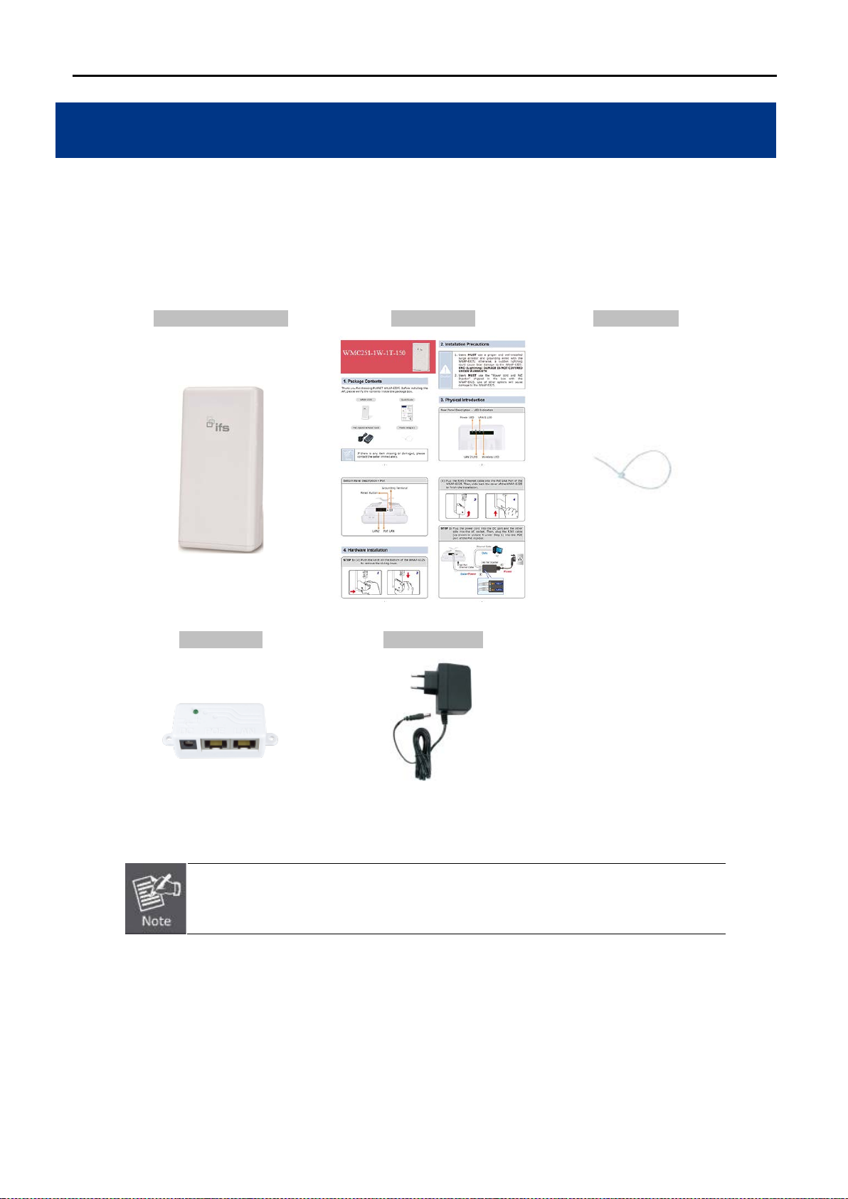
1.1 Package Contents
Thank you for choosing IFS WMC251-1W-2T-150. Before installing the AP, please verify the contents inside the
package box.
WMC251-1W-2T-150 Quick Guide Plastic Strap
If there is any item missing or damaged, please contact the seller immediately.
-1-
Page 14
1.2 Product Des c ription
Cost-effective and Flexi bl e Wireless Solution
IFS WMC251-1W-2T-150 is compatible with IEEE 802.11b/g/n standard and supports a data rate of up to
150Mbps in 802.11n mode. The WMC251-1W-2T-150 not only has a built-in 12dBi panel antenna but also
reserves one RP-SMA type antenna connector to allow versatile antenna installations including omnidirectional,
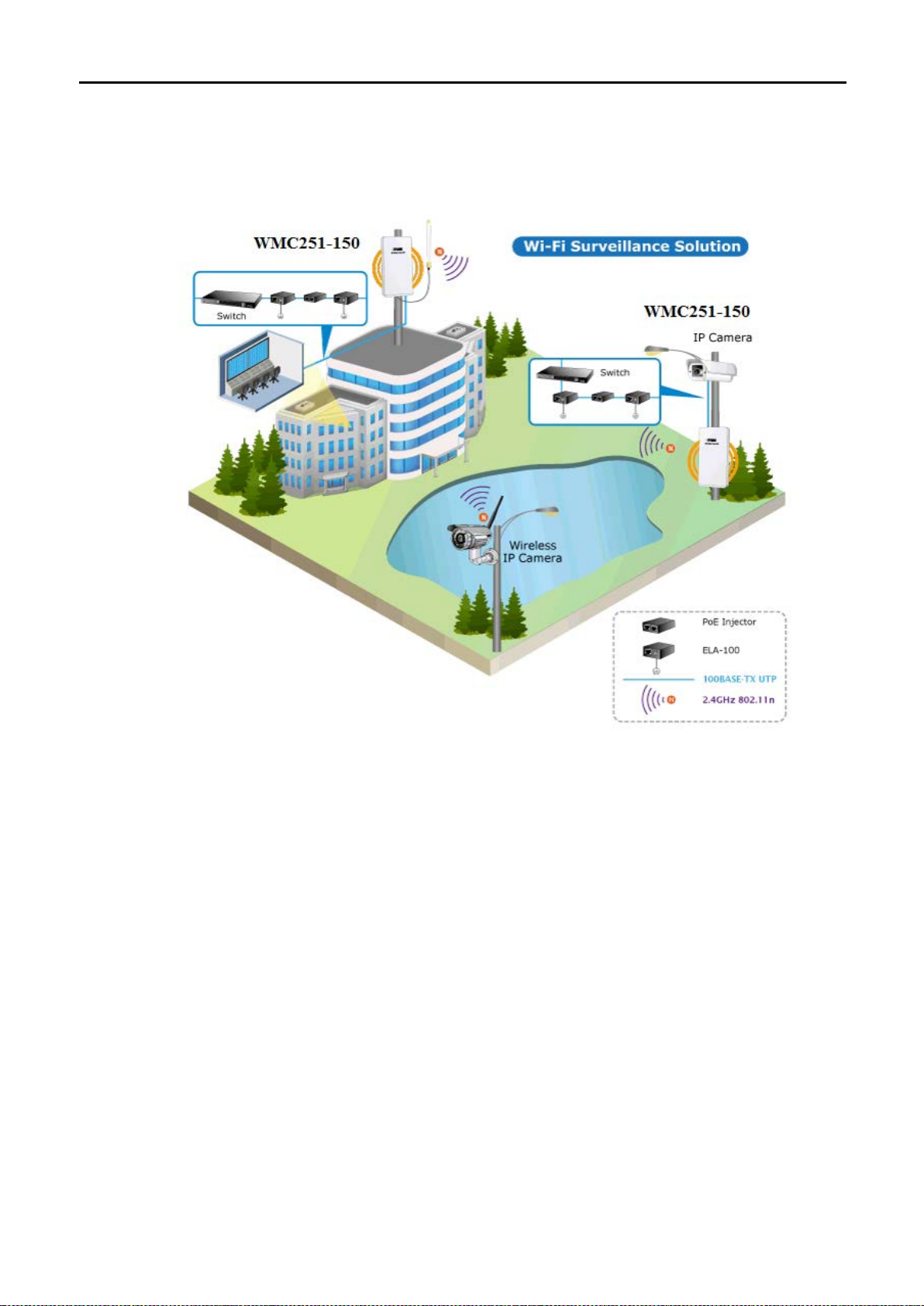
yagi, sector, flat-panel and grid antennas. Furthermore, the WMC251-1W-2T-150 can directly communicate with
the wireless IP cameras by using the popular 2.4GHz frequency band, thus turning the surveillance services into
a wireless environment.
-2-
Page 15

Multiple Operation Modes Designed for Various Applications
The WMC251-150 supports as many as 8 wireless operation m odes including AP Bridge, AP Router, Client
Bridge, Client Router (WISP), WDS PtP, WDS PtM P, Repeater and Universal Repeate r, thus m eeting users’
various application requirements.
Advanced Security and Rigorous Authentication
The WMC251-150 supports WEP , WPA / WPA2, WPA-PSK and WPA2-PSK wireless encryptions, the ad vanced
WPA2-AES mechanism, and 802.1 X RADIUS authentications, which can effectively prevent eavesdropping
from unauthorized users or s top an un aut henticated wireless ac c es s to bandwidth. Users are gr an ted or denied
access to the wireless LAN network based on the ACL (Access Control List) that the administrator
pre-established. In addition, with the multiple-SSID feature, you can set up different wireless networks. The
WMC251-150 c an therefore serve as a virtual access point for segmented networks tailored to an y industrial
need.
Rugged Architecture Provides Reliable Outdoor Connection
The WMC251-150 is equipped with a sturdy and dura ble housing, meeting th e IP55 rating for outdoor usage,
which is definitely suitable for harsh environments. Besides, with its U V-resistant feature, the surface of the
WMC251-150's light weight plastic housing does not yield to brittle fr acture easily. Thus, it is as reliable as the
metal case but more economical. With the proprietary Power over Ethernet (PoE) design, the
WMC251-1W-2T-150 can be easily installed in the areas where power outlets are not available. Additionally, the
reset button on the PoE injector brings convenience to the administrator who can remotely recover the system’s
original setting and the self-healing (schedule reboot) capability to keep connection alive all the time.
Easy Deployment and Management
With user-friendly Web UI and step-by-step setup wizard, the WMC251-150 is easy to install, even for users who
never experience in setting up a wireless network.
-3-
Page 16

1.3 Product Features
Industrial Compliant Wireless LAN and LAN
Compliant with IEEE 802.11n wireless technology capable of having a data rate of up to 150Mbps
Back ward compatible with 802.11b/g standard
Equipped with 10/100Mbps RJ45 ports for LAN and WAN with auto MDI/ MDI-X supported
Fixed-network Broadband Router
Supports WAN connection types: Dynamic IP, static IP, PPPoE, PPTP and L2TP
Supports multiple sessions like IPSec, L2TP and PPTP VPN pass-through
Supports virtual server and DMZ for various networking applications
Supports DHCP server, UPnP and IFS DDNS
RF Interface Characteristics
Built-in 12dBi-directional antenna
High Output Power with multiply-adjustable transmit power control
Optional RP-SMA connector for flexible wireless deployment
Outdoor Environmental Characteristics
IP55-rated outdoor UV-resistant plastic enclosure
Passive PoE design
Reset button on PoE injector
Operating temperature: -20~70 degrees C
Multiple Operations and Wireless Modes
Multiple operation modes: Bridge, Gateway and WISP
Multip le wireless modes: AP Bridge, AP Router, Client Bridge, WDS PtP, WDS PtMP, Repeater,
Universal Repeater and Client Router (WISP)
Supports multiple-SSID to allow users to access different networks through a single AP
Supports WMM (Wi-Fi Multimedia) for better performance
Secure Network Connection
Supports software Wi-Fi Protected Setup (WPS)
Advanced security: 64/128-bit WEP , WP A / WPA2 , WPA-PSK / WPA2-PSK (TKIP/AES) and
802.1X authentication
Supports NAT firewall features with SPI function to protect against DoS attacks
Supports IP / Protocol-based access control and MAC filtering
Easy Installation and Management
Web-based UI and Quick Setup Wizard for easy configuration
System status monitoring includes DHCP Client and System Log
-4-
Page 17

1.4 Product Specifications
2.4GHz 802.11n Wireless Outdoor CPE AP/ Router
IEEE 802.3x
4 Mbytes Flash
LAN 2/ WAN: 1 x 10/100BASE-TX, auto-MDI/MDIX
■ For External Antenna Mode, attach antenna before power on
IEEE 802.11n (40MHz): up to 150Mbps
Data modulation type: O FDM with BPSK, QPSK, 16-QAM, 64-QAM
Europe/ ETSI: 2.412~2.472GHz (13 Channels)
IEEE 802.11n: up to 17 ± 1dBm
IEEE 802.11n: -90dBm
LAN
Built-in DHCP server supporting static IP address distribution
Product
Hardware
Standard Support
Memory
PoE
Interface
Antenna
WMC251-1W-2T-150
IEEE 802.11b/g/n
IEEE 802.3
IEEE 802.3u
32 Mbytes DDR SDRAM
Passive PoE
Wireless IEEE 802.11b/g/n, 1T1R
PoE LAN (LAN 1): 1 x 10/100BASE-TX, auto-MDI/MDIX, passive PoE
Internal (Default): 12dBi directional antenna
■ Horizontal: 30 degree
■ Vertical: 20 degree
External (Optional): RP-SMA type Connector
■ Switchable by Software
Wireless RF Specifications
Wireless Technology
Data Rate
Media Access Control
Modulation
Frequency Band
Operating Channel
RF Output Power (Max.)
Receiver Sensitivity
(dBm)
IEEE 802.11b/g
IEEE 802.11n
IEEE 802.11b: 1, 2, 5.5, 11Mbps
IEEE 802.11g: up to 54Mbps
IEEE 802.11n (20MHz): up to 72Mbps
CSMA/CA
Transmission/Emission type: OFDM
2.412GHz ~ 2.484GHz
America/ FCC: 2.414~2.462GHz (11 Channels)
IEEE 802.11b: up to 26 ± 1dBm
IEEE 802.11g: up to 21 ± 1dBm
IEEE 802.11b: -97dBm
IEEE 802.11g: -90dBm
Output Power Control 5-level TX power control
Software Features
-5-
Page 18

Supports UPnP
Supports IGMP Proxy
Supports 802.1d STP (Spanning Tree)
WAN
L2TP
IPv6
WISP
NAT firewall with SPI (Stateful Packet Inspection)
Built-in NAT server supporting virtual server and DMZ
Built-in firewall with port/ IP address/ MAC/ URL filtering
Universal Repeater (AP+Client)
Enable to isolate each connected wireless client so that they cannot access
mutually
Wireless LAN ACL (Access Control List) filtering
Wireless MAC address filtering
Supports WPS (Wi-Fi Protected Setup )
Enable/Disable SSID Broa dc as t
VPN Passthrough
Operation Mode
Firewall
Static IP
DHCP (Dynamic IP)
PPPoE
PPTP
PPTP
L2TP
IPSec
Gateway
Bridge
Wireless Mode
Max. SSID
Channel Width
Wireless Isolation
Encryption Type
Wireless Securit y
Max. Wireless Clients
AP Bridge
AP Router
Client Bridge
Client Router (WISP)
WDS PtP
WDS PtMP
WDS Repeater
Up to 5
20MHz / 40MHz
64/128-bit WEP, WP A , WP A-PSK, WPA2, WPA2-PSK, 802.1X
20
Max. WDS APs
Max. Wired Clients
8
253
WMM Supports Wi-Fi multimedia
QoS Supports Quality of Service for bandwidth control
NTP Network Time Management
Self Healing
B/G Protection Mode
IAPP Roaming
Management
Supports Schedule Reboot
Supports protection mechanism to prevent collisions among 802.11b/g modes
Supports IAPP (Inter Access Point Protocol) roaming
Web UI, DHCP Client, Configuration Backup and Restore, Dynamic DNS
-6-
Page 19

Diagnostic Tool
System Log
Mechanical and Power
IP Level
Material
Dimensions (W x D x H)
Weight
Installation
IP55
Outdoor UV-resistant enclosure
127 x 63 x 254 mm
485g
Pole mounting or wall mounting
LAN1
12V DC, 1A/ passive PoE
Power Requirements
Pin 4 V DC+
Pin 5 reset
Pin 7, 8 V DC-
Power Consumption
(Max.)
4W
Environment and Certification
Operating Temperature
-20~70 degrees C
Operating Humidity
Regulatory
Accessory
Standard Accessories
10~95% non-condensing
CE, FCC, RoHS
WMC251-1W-2T-150 x 1
12V Power Adapter x 1
PoE Injector x 1
Plastic Strap x 1
Quick Installation Guide x 1
-7-
Page 20
Chapter 2. Hardware Instal lation
Please follow the instructions below to connect WMC251-1W-2T-150 to the existing network devices and your computers.
2.1 Hardware Description
Dimensions: 127 x 63 x 254 mm (W x D x H)
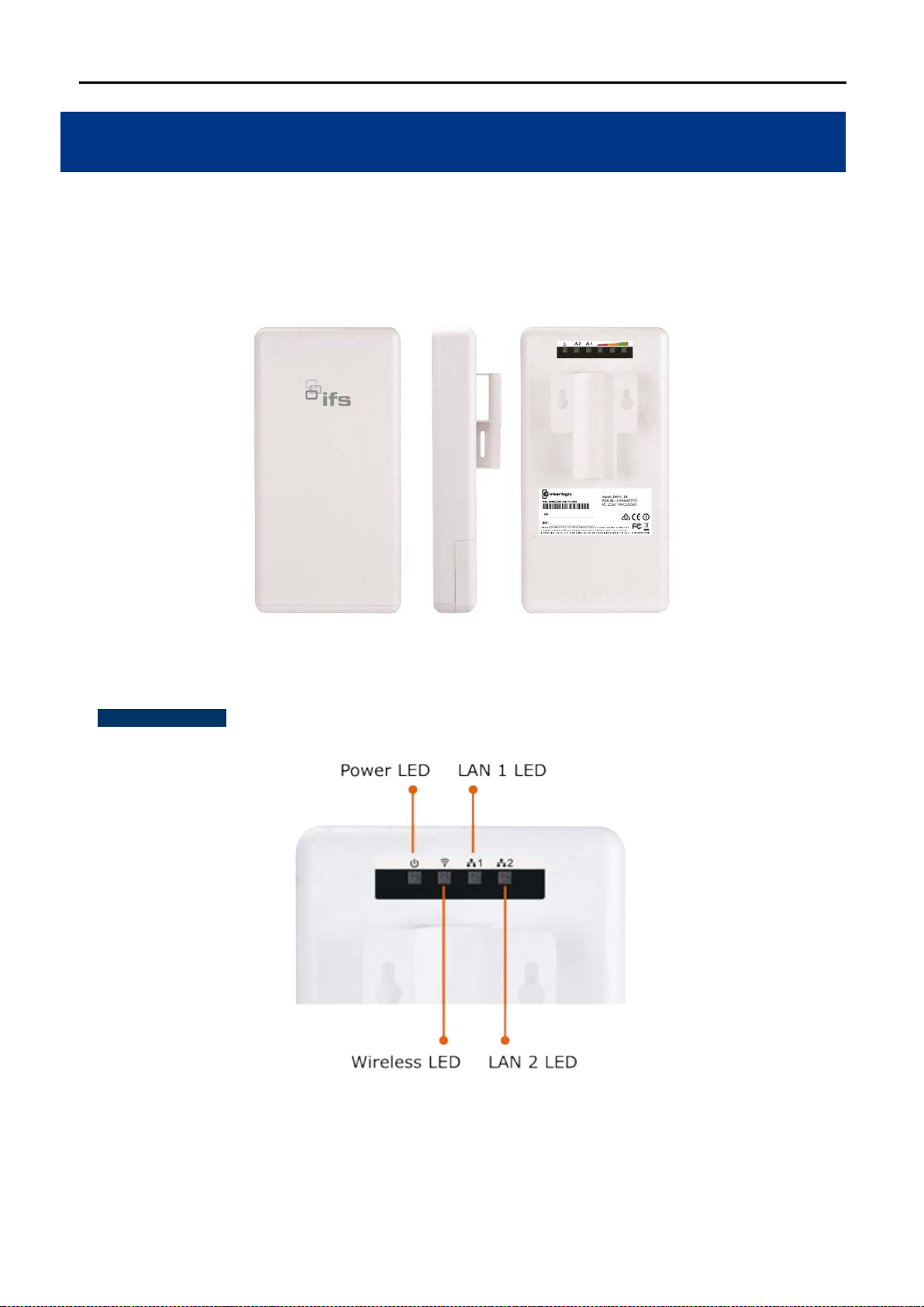
Rear Panel – LED
Figure 2-1 Three-way V i ew
Figure 2-2 LED
-8-
Page 21

LED Definition
LED Color State Meaning
Power
Blue On System On
Blue Off System Off
Blue On Wireless Radio On.
WLAN
Blue Off Wireless Radio Off.
Blue Blinking Data is transmitting or receiving on the wireless.
Blue On Port linked.
LAN1
Blue Off No link.
Blue Blinking Data is transmitting or receiving on the LAN interf ac e.
Blue On Port linked.
LAN2 (WAN)
Blue Off No link.
Blue Blinking Data is transmitting or receiving on the WAN interface.
Table 2-1 The LED Indication
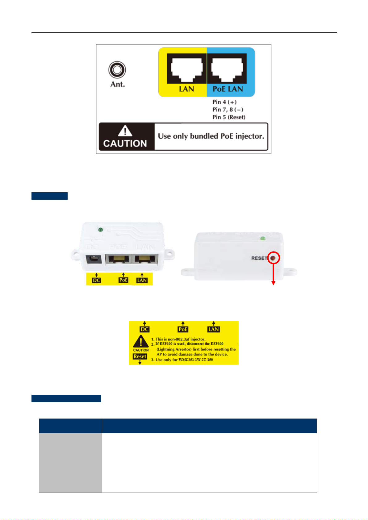
2.1.1 The Bottom Panel – Port
The bottom panel provides the physical connectors connected to the power adapter and any other network
device. Figure 2-3 shows the bottom panel of the WMC251-150.
Bottom Panel
Figure 2-3 Port and Connector of WMC251-150
-9-
Page 22
※
ttach antenna before
from “Internal” to “External” via Web UI.
Reset Button
PoE Injector
Figure 2-4 Port and Connector Description Label
H/W Interface Definition
Interface Function
You can use the RP-SMA connector to connect with the 2.4GHz outdoor
antenna.
RP-SMA Connector
powering on. Then, conf igur e the Anten na S witch (Wireless Advanced page)
Figure 2-5 PoE Injector of WMC251-150
Figure 2-6 Label of PoE Injector
For External Antenna Mode, you MUST physicall y a
-10-
Page 23

LAN (Passive PoE)
Connect this port to the network equipment in bridge mode.
about 10 seconds to
※
,
Remove the thunder protector before
pushing the reset button.
WAN
Reset
10/100Mbps RJ45 port, auto MDI/ MDI-X & passive PoE supported.
Connect LAN port to the PoE injector to power on the d ev ice.
PIN assignment:
Pin 4 VDC+
Pin 5 Reset
Pin 7, 8 VDC-
10/100Mbps RJ45 port, auto MDI/ MDI-X.
Connect this port to the xDSL modem in gateway mode.
Push continually the rese t button on the PoE injector
reset the configuration parameters to factory defaults.
If you have connected with a lightning protector like IFS ESP300
please DO NOT press the reset button on the P oE injector to pr event the
ESP300 from being damaged.
Table 2-2 The PoE Injector Indication
-11-
Page 24

Chapter 3. Connecting to the AP
3.1 Preparation before Installation
3.1.1 Professional Installation Required
Please seek assistance from a professional installer who is well trained in the RF installation and knowledgeable
in the local regulations.
3.1.2 Safety Precautions
1. To keep you safe and install the hardware properly, please read and follow these safety precautions.
2. If you are installing the WMC251-150 for the first t ime, for your safety as well as others’, please seek
assistance from a professional installer who has received safety training on the hazards involved.
3. Keep safety as well as perf ormance in mind when se lecting your installat ion site, especiall y where there
are electric power and phone lines.
4. When installing the WMC251-150, please note the following things:
♦ Do not use a metal ladder;
♦ Do not work on a wet or windy day;
♦ Wear shoes with rubber soles and heels, rubber gloves, long sleeved shirt or jacket.
5. When the system is operational, avoid standing directly in front of it. Strong RF fields are present when the
transmitter is on.
3.2 Installation Precauti ons
Users MUST use a proper and well-installed surge arrestor and grounding kit with WMC251-150;
otherwise, a random lightning could easily cause fatal damage to the WMC251-150. (Lightning
DAMAGE IS NOT COVERED UNDER WARRANTY).
Users MUST use the “PoE Injector” and “Power Adapter” shipped in the box with the WMC251-150.
Otherwise, the product might be damaged.
-12-
Page 25

!
OUTDOOR INSTALLATION WARNING
IMPORTANT SAFETY PRECAUTIONS:
LIVES MAY BE AT RISK! Carefully observe these instructions and any special instructions that are included with the
equipment you are installing.
CONTACTING POWER LINES CAN BE LETHAL. Make sure no power
lines are anywhere w here pos sibl e c ontact can be made. Antennas, masts,
towers, guy wires or cables m ay lean or fal l and cont act t hese lines. Peop le
may be injured or killed if they are touching or holding any part of
equipment when it contacts electric lines. Make sure that equipment or
personnel do not come in contact directly or indirectly with power lines.
The horizontal distance from a tower, mast or antenna to the nearest
power line should be at least twice the total length of the mast/antenna combination. This will ensure that the mast will not
contact power if it falls either during installation or later.
TO AVOID FALLING, USE SAFE PROCEDURES WHEN WORKING AT HEIGHTS ABOVE GROUND.
Select equipment locations that will allow safe, simple equipment inst al lati on.
Don’t work alone. A friend or co-worker can save your life if an accident happens.
Use approved non-conducting lasers and other safety equipment. Make sure all equipment is in good repair.
If a tower or mast begins falling, don’t attempt to catch it. Stand back and let it fall.
If anything such as a wire or mast does come in contact with a power line, DON’T TOUCH IT OR ATTEMPT TO
MOVE IT. Instead, save your life by calling the power company.
Don’t attempt to erect antennas or towers on windy days.
MAKE SURE ALL TOWERS AND MASTS ARE SECUREL Y GROUNDED, A ND ELECTRICAL CABLES CONNECTED TO
ANTENNAS HAVE LIGHTNING ARRESTORS. This will help prevent fire damage or human injury in case of lightning, static
build-up, or short circuit within equipment connected to the antenna.
The base of the antenna mast or tow er must be conne cted dir ectly to the buildi ng pr otectiv e ground or t o one or more
approved grounding rods, using 1OAWG ground wire and corrosion-resist ant co nne ctors.
Refer to the National Electrical Code for grounding details.
IF A PERSON COMES IN CONTACT WITH ELECTRICAL POWER, AND CANNOT MOVE:
DON’T TOUCH THAT PERSON, OR YOU MAY BE ELECTROCUTED.
Use a non-conductive dry board, stick or rope to push or drag them so they no longer are in contact with elec trical
power.
Once they are no longer contacting electrical power, administer CPR if you are certified, and make sure that emergency
medical aid has been requested.
-13-
Page 26

3.3 Installing the AP
Please install the AP acc ording to the following Steps. Don' t forget to pull out the po wer plug and keep your
hands dry.
Step 1. Push the latch on the bottom of the WMC251-150 to remove the sliding cover.
Figure 3-1 Connect the Antenna
Step 2. Plug the RJ45 Ethernet c able into the PoE LAN Port of the WMC251-150. Then, slide back the cover
of the WMC251-150 to finish the installation.
Figure 3-2 Connect the Ethernet cable
Step 3. Plug the power cord into the DC port and plug the other end of the RJ45 cable into the POE port of the
PoE injector (See Step 2).
-14-
Page 27

Step 4. Successful installation.
Figure 3-3 Connect the PoE injector
Figure 3-4 Connect the PoE injector
-15-
Page 28
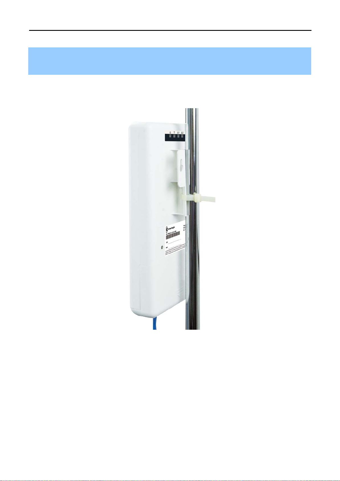
Step 5. Pole Mounting:
Place the strap through the slot on the back of the WMC251-1W-2T-150 and t hen arou nd the pole . Tighten the
strap to secure the WMC251-1W-2T-150.
Figure 3-5 Pole Mounting
-16-
Page 29

ime
Chapter 4. Quick Installation Guide
This chapter will show you how to configure the basic functions of your AP within minutes.
A computer with wired Ethernet connection to th e Wireless AP is required f or the first-t
configuration.
4.1 Manual Network Setup - TCP/IP Configuration
The default IP address of the WMC251-150 is 192.168.0.100. And the default Subnet Mask is 255.255.2 55.0.
These values can be changed as you want. In this guide, we use all the default values for description.
Connect the WMC251-150 with your PC by an Ether ne t cabl e plugging in LAN port on one side and in LAN port
of PC on the other side. Please power on the WMC251-150 by PoE injector through the PoE port.
In the following sections, we’ll introduce how to install and configure the TCP/IP correctly in Windows 7. And the
procedures in other operati ng s ystem s ar e similar. First, make sure your Ethernet Ada pter is working, and refer
to the Ethernet adapter manual if needed.
4.1.1 Configuring the IP Address Manually
Summary:
Set up the TCP/IP Protocol for your PC.
Configure the net work parameters. The IP address is 192.168.1.xxx (if the default IP address of the
WMC251-150 is 192.168.0.100, and the DSL router is 192.168.0.254, the "xxx" can be configured to
any number from 1 to 252), Subnet Mask is 255.255.255.0.
1 Select Use the following IP address radio button, and then configure the IP address of the PC.
2 For example, as the default IP address of the WMC251-150 is 192.168.0.100 and the DSL router is
192.168.0.254, you may choose from 192.168.0.1 to 192.168.0.252.
-17-
Page 30

Figure 4-1 TCP/IP Setting
Now click OK to save your settings.
Now, you can run the Ping command in th e command prompt to verif y the networ k connection between your
PC and the AP. The following example is in Windows 7 OS. Please follow the steps below:
1. Click on Start > Run.
2. Type “cmd” in the Search box.
Figure 4-2 Windows Start Menu
-18-
Page 31

3. Open a command prompt, type ping 192.168.0.100 and then press Enter.
If the result displayed is sim ilar to Figure 4-3, it means the connection bet ween your PC and th e AP
has been established well.
Figure 4-3 Successful result of Ping command
If the result displayed is sim ilar to Figure 4-4, it means the connec tion between your PC and the AP
has failed.
Figure 4-4 Failed Result of Ping Command
If the address is 0.0. 0.0, check your adapter installation, sec urity settings, an d the settings on your AP. Some
firewall software programs may block a DHCP request on newly installed adapters.
-19-
Page 32

4.2 Starting Setup in the Web UI
It is easy to configure and manage the AP with the web browser.
Step 1. To access the configuration utility, open a web-browser and enter the default IP address
http://192.168.0.100 in the web address field of the browser.
Figure 4-5 Login by default IP address
After a moment, a logi n w indow will ap pear. Enter admin for the User N am e and Passwor d, bot h in lower cas e
letters. Then click the OK button or press the Enter key.
Default IP Address: 192.168.0.100
Default User name: admin
Default Password: admin
If the above screen does not pop up, it may mean that your web-browser has been set to a
proxy. Go to Tools menu>Internet Options>Connections>LAN Settings on the screen
that appears, cancel the Using Proxy checkbox, and click OK to finish it.
Figure 4-6 Login Window
-20-
Page 33

Chapter 5. Configuring the AP
This chapter deliver s a detailed presentation of AP’s functionalities and feat ures under the m ain menu below,
allowing you to manage the AP with ease.
Figure 5-1 Main Menu
5.1 Setup Wizard
The Setup Wizard will gu ide t h e user t o c onf ig ur e t he WMC251-1W-2T-150 easil y and qu ic kly. Select the Setup
Wizard on the l eft s ide of the screen an d by clicking on N ext on the Setup Wizard screen show n bel o w, you will
then name your WMC251-1W-2T-150 and set up its security.
Figure 5-2 Setup Wizard
Step 1: Setup Operation Mode
The AP supports three operation modes, Gateway, Bridge and Wireless ISP.
-21-
Page 34

Each mode is suitable for different uses. Please choose the correct mode.
Figure 5-3 Wizard –Setup O per ation Mode
-22-
Page 35

Step 2: Time Zone Setting
The Time Configuration op tion allows you to configur e, update, and maintain the c orrect time on the inter nal
system clock. Daylight Saving can also be configured to automatically adjust the time when needed.
Figure 5-4 Wizard – Time Zone Setup
Step 3: Setup LAN Interface
Figure 5-5 Wizard – Setup LAN Interface
Step 4: Setup WAN Interface
The W ireles s AP supports five access modes in the WAN side. Pleas e choose the correct m ode according t o
your ISP Service.
-23-
Page 36

Figure 5-6 Wizard – WAN Interface Setup
Step 5: Wireless LAN Setting
Configure the wireless param eters accor ding to your appl ication. For t his section you can set AP, Client, WDS
and AP+WDS (Repeater) mode.
Figure 5-7 Wizard - Wireless LAN Setting
Step 6: Wireless Security Setting
Secure your wireless network by turning on the WPA or WEP security feature on the AP. For this section you can
set WEP and WPA-PSK security mode.
-24-
Page 37

Figure 5-8 Wizard - Wireless Security Setting
Click the Finished button to make your wireless configuration to take effect.
-25-
Page 38

5.2 Operation Mode
This page shows the current operation mode, and users can set different modes to LAN and WLAN interface for
NAT and bridging function on the WMC251-150.
Figure 5-9 Operation Mode
-26-
Page 39

The page includes the following fields:
user to share Internet via
Object Description
Gateway
In this mode, the device enables multiADSL/Cable Modem. The wireless port shares the same IP to ISP
through Ethernet WAN port. The Wireless port acts the same as a LAN
port while at AP Router mode.
Bridge
Wireless ISP
In this mode, the device can be used to combine multiple local
networks together to the same one via wireless connections, especially
for a home or office where separated networks can't be connected
easily together with a cable.
In this mode, the device enables multi-user to share Internet from
WISP. The LAN port devices share th e same IP from WISP through
Wireless port. While conne cting to WISP, the Wirel ess po rt w orks as
a WAN port at Client Router m ode. The Ethernet p ort acts as a LAN
port.
-27-
Page 40

192.168.0.100. You can change it according to your request.
addresses to clients.
the Active DHCP Client Table.
addresses anytime when they request IP addresses.
5.3 TCP/IP Settings
This page is used to configure the parameters for local area network which connects to the LAN port of your AP.
Here you may change the setting for IP address, subnet mask, DHCP, etc.
5.3.1 LAN Interface
On the LAN Settings page, you can configure the IP parameters of the LAN on the screen as shown below.
The page includes the following fields:
Object Description
IP Address The default LAN IP address of the WMC251-1W-2T-150 is
Subnet Mask Default is 255.255.255.0. You can change it according to your request.
Default Gateway Default is 192.168.0.100. You can change it according to your request.
DHCP You can select a Disabled, Client, and Server. Default is Disabled,
meaning the WMC251-150 must connect to a router to assign IP
DHCP Client Range For the Server mode, you must enter the DHCP client IP address
range in the field. And you can click the “Show Client” button to show
Static DHCP Click the “Set Static DHCP” button and you can reserve some IP
addresses for those network devices with the specified MAC
Figure 5-10 LAN Setting
-28-
Page 41

the LAN.
Domain Name Default is IFS.
802.1d Spanning Tree You can enable or disable the Spanning Tree function.
Clone MAC Address You can input an MAC address here for using clone function.
UPnP Enable You can enable or disable the UPnP function.
The UPnP feature allows the devices, such as Internet computers, to
access the local host resources or devices as needed. UPnP devices
can be automatically discovered by the UPnP service application on
If you change the IP address of LAN, you must use the new IP address to login the
AP.
When the IP address of t he WMC251-150 is c hanged, the clients on the network
often need to wait for a while or even reboot before the y can access the n ew IP
address. For an immediate access to the AP, please flush the netbios cache on the
client computer by running the “nbtstat –r” command before using the device
name of the WMC251-150 to access its Web Management page.
5.3.2 WAN Interface
On the WAN Settings page, you can configure the IP parameters of the WAN on the screen as shown below.
-29-
Page 42

The page includes the following fields:
Figure 5-11 WAN Setting
Object Description
-30-
Page 43

Select Static IP Address if all the Internet port’s IP information is
(Internet Service Prov ider). You will need
nd DNS
Each IP address entered in the fields must be in the appropriate IP
l over Ethernet) if your ISP uses
a PPPoE connection. Your ISP will provide you with a us ername and
Tunneling Protocol) if your ISP uses a
PPTP connection. Your ISP will provide you with IP information and
it also includes a username and
Password
WAN Acces s Ty pe
Please select the corresponding WAN Access Type for the Internet, and fill the
correct parameters from your local ISP in the fields which appear below.
DHCP Client
Select DHCP Client to obtain IP Address information automatically
from your ISP.
Static IP
provided to you b y your ISP
to enter the IP address, subnet mask, gateway address, a
address provided to you by your ISP.
form, which are four octets separated by a dot (x.x.x.x). The Router will
not accept the IP address if it is not in this format.
IP Address
Enter the IP address assigned by your ISP.
Subnet Mask
Enter the Subnet Mask assigned by your ISP.
Default Gateway
Enter the Gateway assigned by your ISP.
DNS
The DNS server information will be supplied by your ISP.
PPPoE
Choose PPPoE (Point to Point Protoco
password. This option is typically used for DSL services.
User Name
Enter your PPPoE user name.
Password
Enter your PPPoE password.
PPTP
Choose PPTP (Point-to-Point-
PPTP Server IP Address; of course,
password. This mode is typically used for DSL services.
IP Address
Enter the IP address.
Subnet Mask
Enter the Subnet Mask.
Server IP Address
Enter the PPTP Server IP address provided by your ISP.
User Name
Enter your PPTP user name.
-31-
Page 44

uses a L2TP
Enter your PPTP password.
L2TP
Choose L2TP (Layer 2 Tunneling Protocol) if your ISP
connection. Your ISP will provide you with a username and password.
IP Address
Enter the IP address.
Subnet Mask
Enter the Subnet Mask.
Server IP Address
Enter the L2TP Server IP address provided by your ISP.
User Name
Enter your L2TP user name.
Password
Enter your L2TP password.
Host Name
This option specifies the Host Name of the Wireless AP.
MTU Size The normal MTU (Maximum Transmission Unit) valu e for most Ethernet net works is
1492 Bytes. It is not recom mended that you change the default MTU Size unless
required by your ISP.
Attain DNS
Automatically
Select “Attain DNS Automatically”, the D NS servers will be assigned d ynamically
from your ISP.
Set DNS Manually If your ISP gives you one or two DNS addresses, select Set DNS Manually and enter
the primary and secondary addresses into the correct fields.
Clone MAC
You can input a MAC address here for using clone function.
Address
Enable uPNP
Enable IGMP Proxy
Enable Ping Access
Check to disable/enable uPNP function (default = disabled)
Check to disable/enable IGMP function (default = enabled)
Check to enable the Ping Access on WAN function (default = disabled)
on WAN
Enable Web Server
Check to enable the Web Server Access on WAN function (def ault = disabled)
Access on WAN
Enable IPsec pass
through on VPN
Check to enable the IPsec pass through on VPN connection function (default =
enabled)
connection
Enable PPTP pass
through on VPN
connection
Enable L2TP pass
through on VPN
connection
Check to enable the PPTP pass through on VPN connection function (default =
enabled)
Check to enable the L2TP pass through on VPN connection function (default =
enabled)
-32-
Page 45

u get Address not foun d error when you acces s a Web site, it is likel y that
your DNS servers are set up improperly. You should contact your ISP to get
WAN IP, whether obtained autom aticall y or specified m anually, should NOT be
otherwise, the router will not work
Enable IPv6 pass
through on VPN
Check to enable the IPv6 pass through on VPN connection function (default =
disabled)
connection
If yo
DNS server addresses.
on the s ame IP net segm ent as the LAN IP;
properly. In case of emergency, press the hardware "Reset" button.
5.4 Wireless
The wireless menu contains submenus of the settings about wireless network. Please refer to the following
sections for the details.
Figure 5-12 Wireless – Main Menu
5.4.1 Basic Settings
Choose menu “Wireless Basic Settings” and you can conf igure the wireless bas ic settings f or the wireless
network on this page. After the configuration is done, please click the “Apply Changes” button to save the
settings.
First of all, the wireless AP supports multiple wireless modes for different network applications, which include:
AP
Multiple SSIDs
Univ ersal Repeater
Client
WDS
AP+WDS
It is so easy to com bine the WMC251-1W-2T-150 with the existing wired network . The WMC251-1W-2T-150
definitely provides a total network solution for the home and the SOHO users.
-33-
Page 46

AP
Disable Wireless LAN
Standard Access Point
Figure 5-13 Topology – AP Bridge Mode
The page includes the following fields:
Object Description
Figure 5-14 Wireless Basic Settings of AP
Check the box to disable the wireless function.
-34-
Page 47

the status table of
Interface
Band Select the desired m ode. Default is “2.4GHz (B+G+N)”. It is strongl y
recommended that you set the Band to “2.4G Hz (B+ G+N)”, and a ll of
802.11b, 802.11g, and 802.11n wireless stations can connect to the
WMC251-1W-2T-150.
2.4 GHz (B): 802.11b mode, rate is up to 11Mbps
2.4 GHz (G): 802.11g mode, rate is up to 54Mbps
2.4 GHz (N): 802.11n mode, rate is up to 150Mbps(1T1R)
2.4 GHz (B+G): 802.11b/g mode, rate is up to 11Mbps or 54Mbps
2.4 GHz (G+N): 802.11g/n mode, rate is up to 54Mbps or 150Mbps
2.4 GHz (B+G+N): 802.11b/g/n mode, rate is up to 11Mbps,
54Mbps, or 150Mbps
Mode
There are four kinds of wireless mode selections:
AP
Client
WDS
AP+WDS
If you select WDS or AP+WDS, please click “WDS Settings” submenu
for the related configuration. Furthermore, click the “Multiple AP”
button to enable multiple SSID function.
SSID
The ID of the wireless network. U ser can acc ess the wireless network
via the ID only. However, if you switch to Client Mode, this field
becomes the SSID of the AP you want to connect with .
Default: WMC251-150
Channel Width You can select 20MHz, or 40MHz.
Channel Number
You can select the operating frequency of wireless network.
Default: 11
Broadcast SSID
If you enable “Broadc ast SSID”, every wire less station located within
the coverage of the AP can discover its signal easily . If you are building
a public wireless network, enabling this feature is recommended. In
private network, disabling “Broadcast SSID” can provide better
wireless network security.
Default is “Enabled”.
Data Rate
Associated Clients
Set the wireless data transfer rate to a certain value. Since most of
wireless devices will negotiate with eac h other and p ick a proper data
transfer rate autom atically, it’s not necessary to change this value
unless you know what will happen after modification.
Default is “Auto”.
Click the “Show Active Clients” button to show
active wireless clients.
-35-
Page 48

Enable Universal
Repeater Mode
(Acting as AP and client
simultaneously)
Universal Repeater is a tec hnolog y used to exten d wir eless cov erag e.
To enable Universal Repeater mode, check the box and enter the
SSID you want to broadcast in the field below. Then please click
“Security” submenu for the related settings of the AP you want to
connect with.
Multiple-SSID
Enable multiple-SSI D c an broadc ast multiple WLAN SSID's using virtua l int erf aces. You can have different
encryption settings for each WLAN and you can restrict what they have access to.
Figure 5-15 Topology – Multiple-SSID Mode
Choose menu “Wireless → Basic Settings → Multiple AP” to configure t he de vice as a general wireless
access point with multiple SSIDs.
Figure 5-16 Wireless Basic Settings – Multiple AP
The device supports up to four multiple Service Set Identifiers. You can back to the Basic Sett in gs page to
set the Primary SSID. T he SSID’s factor y default setting is WMC251-1W-2T-150 VAP1~4 (Multiple-SSID
1~4). The SSID can be easily changed to connec t to an existing wireless network or to establish a new
wireless network. When the information for the new SSID is finished, click the Apply Changes button to let
your changes take effect.
-36-
Page 49

Figure 5-17 Multiple-SSID
Once you have applie d and saved thos e settings, you can then go t o the “Wireless → Security” page on
the AP to set up security settings for each of the SSIDs.
Universal Repeater
This mode allows the AP with its own BSS to relay data to a root AP to which it is assoc iated with WDS
disabled. The wireless repeater relays signal between its stations and the root AP for greater wireless
range.
Figure 5-18 Topology – Universal Repeater Mode
1. Example of how to configure Universal Repeater Mode. Please take the following steps:
To configure each wireless parameter, please go to the “Wireless→ Basic Settings” page.
Step 1. Configure wireless mode to “AP” and then check “Enable Universal Repeater Mode (Acting as AP
and client simultaneously)”. Click “Apply Changes” to take effect.
-37-
Page 50

Figure 5-19 Universal Repeater-1
Step 2. Go to Site Surve y page t o find the r oot AP. Select the root A P that you want t o repeat the signal and
then click “Next”.
-38-
Page 51

Figure 5-20 Universal Repeater-2
Step 3. Select the correct encryption method and enter the security key. Then, click “Connect”.
Figure 5-21 Universal Repeater-3
Step 4. Check “Add to Wireless Profile” and click “Reboot Now”.
-39-
Page 52

Figure 5-22 Universal Repeater-4
Step 5. Go to “Management-> Status” page to check whether the state of Repeater interface should be
“Connected”.
Figure 5-23 Universal Repeater-5
Client (Infrastructure)
Combine the Wireless AP to the Ethernet devices such as IP camera to make it be wireless station.
Figure 5-24 Topology – Client Mode
-40-
Page 53

Figure 5-25 Wireless Basic Settings – Client
-41-
Page 54

Disable Wireless LAN
The page includes the following fields:
Object Description
Check the box to disable the wireless function.
Interface
Band Select the desired m ode. Default is “2.4GHz (B+G+N)”. It is strongl y
recommended that you set the Band to “2.4G Hz (B+G +N)”, and all of
802.11b, 802.11g, and 802.11n wireless stations can connect to the
WMC251-150.
2.4 GHz (B): 802.11b mode, rate is up to 11Mbps
2.4 GHz (G): 802.11g mode, rate is up to 54Mbps
2.4 GHz (N): 802.11n mode, rate is up to 150Mbps(1T1R)
2.4 GHz (B+G): 802.11b/g mode, rate is up to 11Mbps or 54Mbps
2.4 GHz (G+N): 802.11g/n mode, rate is up to 54Mbps or 150Mbps
2.4 GHz (B+G+N): 802.11b/g/n mode, rate is up to 11Mbps,
54Mbps, or 150Mbps
Mode
There are four kinds of wireless mode selections:
AP
Client
WDS
AP+WDS
If you select WDS or AP+WDS, please click “WDS Settings” submenu
for the related configuration. Furthermore, click the “Multiple AP”
button to enable multiple SSID function.
Network Type In Infrastructure, the wireless LAN serves as a wireless stat ion. And
the user c an use the PC equipped with the WMC251-150 to access
the wireless net work via other access points. In Ad hoc, the wireless
LAN will use the Ad-hoc mode to operate.
Default is “Infrastructure”.
Note: only while the wireless mode is set to “Client”, then the Network
Type can be configured.
SSID
The ID of the wireless network. U ser can acc ess the wireless network
via the ID only. However, if you switch to Client Mode, this field
becomes the SSID of the AP you want to connect with.
Default: WMC251-150
Broadcast SSID
If you enable “Broadc ast SSID”, every wire less station located within
the coverage of the WMC251-150 can discover its sig nal eas il y. If you
are building a public wireless network, enabling this feature is
recommended. In private network, disabling “Broadcast SSID” can
provide better wireless network security.
Default is “Enabled”.
-42-
Page 55

Data Rate
Set the wireless data transfer rate to a certain value. Since most of
wireless devices will negotiate with eac h other and p ick a proper data
transfer rate autom atically, it’s not necessary to change this value
unless you know what will happen after modification.
Default is “Auto”.
Enable Mac Clone
Enable Mac Clone.
(Single Ethernet Client)
Example of how to configure Client Mode. Please take the following steps:
To configure each wireless parameter, please go to the “Wireless → Basic Settings” page.
Step 1. Go to “Wireless → Site Survey” pa ge and click “Site Survey” button.
Figure 5-26 Client – Survey
-43-
Page 56

Step 2. Choose the root AP from the list. If the root AP is not listed in the table, re-click “Site Survey” to update
the list.
Figure 5-27 Client – AP List
Step 3. Enter the Securit y Key of the root AP and then click “Connect”.
Figure 5-28 Client – Security
-44-
Page 57

Step 4. Wait until the connection established. Check the “Add to Wireless Profile” option and then reboot it.
Figure 5-29 Client – Status
WDS
Connect this Wireless AP with up to 8 WDS-capable wireles s APs to expand the scope of network.
Figure 5-30 Topology – WDS PtP Mode
Figure 5-31 Topology – WDS PtMP Mode
-45-
Page 58

Disable Wireless LAN
2.4 GHz (G+N)
Figure 5-32 Wireless Basic Settings – WDS
The page includes the following fields:
Object Description
Check the box to disable the wireless function.
Interface
Band Select the desired m ode. Default is “2.4GHz (B+G+N)”. It is strongly
recommended that you set the Band to “2.4G Hz (B+ G+N)”, and a ll of
802.11b, 802.11g, and 802.11n wireless stations can connect to the
WMC251-150.
2.4 GHz (B): 802.11b mode, rate is up to 11Mbps
2.4 GHz (G): 802.11g mode, rate is up to 54Mbps
2.4 GHz (N): 802.11n mode, rate is up to 150Mbps(1T1R)
2.4 GHz (B+G): 802.11b/g mode, rate is up to 11Mbps or 54Mbps
: 802.11g/n mode, rate is up to 54Mbps or 150Mbps
-46-
Page 59

2.4 GHz (B+G+N): 802.11b/g/n mode, rate is up to 11Mbps,
54Mbps, or 150Mbps
Mode
There are four kinds of wireless mode selections:
AP
Client
WDS
AP+WDS
If you select WDS or AP+WDS, please click “WDS Settings” submenu
for the related configuration. Furthermore, click the “Multiple AP”
button to enable multiple SSID function.
Channel Width You can select 20MHz, or 40MHz
Control Sideband You can select Upper or Lower.
Channel Number
Data Rate
You can select the operating frequency of wireless network.
Set the wireless data transfer rate to a certain value. Since most of
wireless devices will negotiate with each other and pick a proper data
transfer rate autom atically, it’s not necessary to change this value
unless you know what will happen after modification.
Default is “Auto”.
AP+ WDS
Connect this Wireless AP with up to 8 WDS-capable wireless APs, and connect another AP to provide
service for all wireless stations within its coverage.
Figure 5-33 Topology – WDS+AP Mode
-47-
Page 60

Disable Wireless LAN
Interface
the wireless f unct ion of the Router
d. If your country
for
2.4 GHz (B)
Figure 5-34 Wireless Basic Settings – WDS+AP
The page includes the following fields:
Object Description
Check the box to disable the wireless function.
Country
Select your region from the pull-down lis t.
This field specif ies the reg ion where
can be used. It ma y be illegal to use the wirel ess f unction of the R outer
in a region other than one of thos e specif ied in this f ie l
or region is not listed, plea se contact your local governm ent agenc y
assistance.
Band Select the desired m ode. Default is “2.4GHz (B+G+N)”. It is strongl y
recommended that you set the Band to “2.4G Hz (B+ G+N)”, and a ll of
802.11b, 802.11g, and 802.11n wireless stations can connect to the
WMC251-150.
: 802.11b mode, rate is up to 11Mbps
-48-
Page 61

Mode
the status table of
2.4 GHz (G): 802.11g mode, rate is up to 54Mbps
2.4 GHz (N): 802.11n mode, rate is up to 150Mbps(1T1R)
2.4 GHz (B+G): 802.11b/g mode, rate is up to 11Mbps or 54Mbps
2.4 GHz (G+N): 802.11g/n mode, rate is up to 54Mbps or 150Mbps
2.4 GHz (B+G+N): 802.11b/g/n mode, rate is up to 11Mbps,
54Mbps, or 150Mbps
There are four kinds of wireless mode selections:
AP
Client
WDS
AP+WDS
If you select WDS or AP+WDS, please click “WDS Settings” submenu
for the related configuration. Furthermore, click the “Multiple AP”
button to enable multiple SSID function.
SSID
The ID of the wireless network. U ser can acc ess the wireless network
via the ID only. However, if you switch to Client Mode, this field
becomes the SSID of the AP you want to connect with.
Default: WMC251-1W-2T-150
Channel Width You can select 20MHz, or 40MHz
Control Sideband You can select Upper or Lower.
Channel Number
Broadcast SSID
You can select the operating frequency of wireless network.
If you enable “Broadc ast SSID”, every wire less station located within
the coverage of the WMC251-150 can discover its sig nal eas il y. If you
are building a public wireless network, enabling this feature is
recommended. In private network, disabling “Broadcast SSID” can
provide better wireless network security.
Default is “Enabled”.
Data Rate
Set the wireless data transfer rate to a certain value. Since most of
wireless devices will negotiate with eac h other and p ick a proper data
transfer rate autom atically, it’s not necessary to change this value
unless you know what will happen after modification.
Associated Clients
Enable Universal
Repeater Mode
(Acting as AP and client
simultaneously)
Default is “Auto”.
Click the “Show Active Clients” button to show
active wireless clients.
Universal Repeater is a tec hnolog y used to exten d wir eless cov erag e.
To enable Universal Repeater Mode, check the box and enter the
SSID you want to broadcast in the field below. Then please click
“Security” submenu for the related settings of the AP you want to
connect with.
-49-
Page 62

5.4.2 Advanced Settings
Choose menu “Wireless Advanced Settings” to c onfigure the wireless advanced s ettings for the wireless
network on this page. After the configuration, please click the “Apply Changes” button to save the settings.
Figure 5-35 Wireless Advanced Settings
-50-
Page 63

Object
Description
Default is “2346”.
Default is “2347”.
communication. Def ault is “Long Preamble”.
Default is “Enabled”.
Default is “Disabled”.
Default is “Enabled”
Default is “Enabled”
exchange data through the
Default is “Disabled”.
which does not need
Default Setting: "Enabled"
Default Setting: "Enabled"
Default Setting: "Disabled"
unicast traffic
Converting multicast traffic to unicast
Rate) interval to be set. A longer DTIM interval prevents clients in
power-save mode having to activate their radios to receive the multicast
The page includes the following fields:
Fragment Threshold You can specify the m aximum size of pack et during th e fragm entation
of data to be transm itted. If you set th is value too low, it will result in
bad performance.
RTS Threshold When the packet size is s maller than the RTS thres hold, the access
point will not use the RTS/CTS mechanism to send this packet.
Beacon Interval The interval of time that this access point broadcasts a beacon.
Beacon is used to synchronize the wireless network. Default is “100”.
Preamble Type Preamble t ype defines the length of CRC block in the frames during
the wireless communication. “Short Preamble” is suitable for high
traffic wireless network . “Long Preamble” can provide m ore reliable
IAPP IAPP (Inter-Access Point Protocol) enabled is recommended as it
describes an optional ext ension to I EEE 802.11 that provides wireless
access-point communications among multivendor systems.
Protection
Enables a backward compatible protection mechanism for 802.11b
clients. When the protectio n m ode is en abled can slow the throughput
of the 802.11g/n clients by as much as 50%.
Aggregation It is a function where the values of m ultiple ro ws ar e groupe d toge t her.
Short GI It is used to set the time that the receiver waits for RF reflections to
settle out before sampling data.
WLAN Partition This feature also called “WL AN isolation” or “Block Relay”. If this is
enabled, wireless clients cannot
WMC251-1W-2T-150.
STBC Activate Space Time Blocking Code (STBC)
channel statement information (CSI).
LDPC Low-density Parity-check Code is wireless data transmit algorithm.
20/40MHz Coexist Configure 20/40MHz coexisting scheme.
If you set up as "Enabled", "20MHz" and "40MH z" wil l coex ist .
Multicast to Unicast: Enables multicast traffic streams to be converted to
before delivery to wir eless c lients.
before sending to wireless clients allows a long er DTIM (Data Beacon
-51-
Page 64

Default Setting: “Enabled”
Default is “100%”.
data, which reduce power consumption.
RF Output Power Users can adjust the wireless output power to different levels. For
short distance of PtP connec tion wit hin 1Km , it is sug gested t o red uce
the output power to 50% or lower to prevent interference with each
other.
5.4.3 Security
Choose menu “Wireless Security” to configur e the sett ings of wireles s security for the wireles s network on
this page. After the configuration, please click the “Apply Changes” button to save the settings.
Figure 5-36 Wireless Security Settings
The page includes the following fields:
Object Description
Select SSID
Select the SSID you want to configure the wireless security function, which
includes the root one and the client one.
Encryption Disable:
No security setup for wireless connection.
WEP:
It is based on the IEEE 802.11 standard. And the default setting of
authentication is Automatic, which can select Open System or Shared Key
authentication type automatically based on the wireless station's capa bility
and request. Furthermore, you can select Key Length and enter 10 and 26
Hexadecimal digits (any combination of 0-9, a-f, A-F, zero key is not
promoted) or 5 and 13 ASCII characters in the Encryption Key field.
WPA2:
WPA2 is a high level encryption and is supp orted by m ost wireless devices
and operating systems.
WPA-Mixed:
WPA Mixed Mode allows the use of both WPA and WPA2 at the same time.
-52-
Page 65

Authentication Mode
Enterprise (RADIUS)
When you select the authentication mode based on Enterprise (Radius
Server), please enter the IP Address, Port, and Password of the Radius
Server.
Personal (Pre-Shared Key)
When you select the other authentication mode based on Personal
(Pre-Shared Key), please enter at least 8 ASCII c hara cters (Pas sphrase) or
64 Hexadecimal characters. All of the Cipher Suites support TKIP and AES.
802.1x Authentication
Enable 802.1x authenticati on function and then enter the IP Address, Port,
and Password of the Radius Server.
Disable:
Authentication is disabled and no password/key is required to connect to the access point.
WEP:
WEP (Wired Equivalent Privacy) is a basic encryption. For a higher level of securit y consider using the WPA
encryption.
The page includes the following fields:
Figure 5-37 Security Settings – WEP
Object Description
You can disable the encryption or sel ect WEP, WPA2, and WPA-Mixed
Encryption
as the encryption method to your wireless network.
802.1x
Authentication
Enable 802.1x authentication function and then enter the IP Address,
Port, and Password of the Radius Server.
Configures the WEP security mode used by clients.
Authentication
When using W EP, be sure to defin e at l east o ne sta tic W E P ke y for the
Wireless AP and all its clients.
-53-
Page 66

There are three options provided:
Open System — this authentication accepts any client attempting to
connect the Wireless AP without verifying its identity.
Shared Key — the shared-key security uses a WEP key to authenticate
clients connecting to the network and for data encryption.
Auto — allows wireless clients to connect to the network using
Open-WEP (uses WEP for encryption only) or Shared-WEP (uses WEP
for authentication and encryption).
Key Length Choose the WEP key length. You can choose 64-bit or 128-bit.
Key Format You can choose ASCII or Hex format.
Enter 5 alphanumeric characters or 10 hexadecimal digits for 64-bit
Encryption Key
keys, or enter 13 alphanu meric characters or 26 hexadecimal digits f or
128-bit keys.
WPA2:
Wi-Fi Protected Access (WPA) was introduced as an interim solution f or the vulnerabili ty of WEP pending t he
adoption of a more r obust wireless s ecurity standard. W PA2 includes the complete wireless secur ity standard,
but also offers backward compatibility with WPA. Both WP A and WP A2 provide an enterprise and personal mode
of operation.
Figure 5-38 Security Settings – WPA2 Personal
The page includes the following fields:
Object Description
You can disable the encryption or select WEP, WPA2, and WP A-Mixed as the
Encryption
encryption method to your wireless network.
Select “Enterprise (RADIU S)” for user aut hentication and you will requ ire a
Authentication Mode
RADIUS authenticat ion server to be configured on the wire d network. Select
-54-
Page 67

unprotected and unencrypted 802.11 management messages passed
“Personal (Pre-Shared Key)” and you will require a pre-shared key to be
configured for client authentication.
Management frame protection (MFP) provides security for the otherwise
Management Frame
Protection
WPA2 Cipher Suite
between access points and clients. MFP provides both infrastructure and
client support.
If you choose this to “Requ ired”, then clients are allowed to
associate only if MFP is negotiated. If you choose “Capable”, then the
non-supporting clients are allows to associate (without using MFP).
Selects the data encryption type to use. (Default is determined by the
Encryption Mode selected.)
TKIP — Uses Temporal Key Integrity Protocol (TKIP) keys for encryption.
WPA specifies TKIP as the data encryption method to replace WEP. TKIP
avoids the problems of WEP static keys by dynamically changing data
encryption keys.
AES — Uses Advanced Encryption Standard (AES) keys for encryption.
WPA2 uses AES Counter-Mode encryption with Cipher Block Chaining
Message Authentication Code (CBC-MAC) for message integrity. The AES
Counter-Mode/CBCMAC Protocol (AESCCMP) provides extremely robust
data confidentiality using a 128- bit key. Use of AES-CCMP encryption is
Pre-Shared Key Format
Pre-Shared Key
specified as a standard requirement for WPA2. Before implementing WPA2 in
the network, be sure client devices are upgraded to WPA2-compliant
hardware.
Specify the format of the key, pass phrase or hex.
The WPA Pre-shared Key can be input as an ASCII string (an
easy-to-remember form of letters and numbers that can include spaces) or
Hexadecimal format. (Range: 8~63 ASCII characters, or exactly 64
Hexadecimal digits)
Enter the key whose format is limited by the key format.
-55-
Page 68

unprotected and unencrypted 802.11 management messages passed
Figure 5-39 Security Settings – WPA2 Enterprise
The page includes the following fields:
Object Description
You can disable the encryption or select WEP, WPA2, and WPA-Mixed as the
Encryption
encryption method to your wireless network.
Select “Enterprise (RADIU S)” for user aut hentication and you will requ ire a
RADIUS authentication server to be configured on the wired network . Select
Authentication Mode
“Personal (Pre-Shared Key)” and you will require a pre-shared key to be
configured for client authentication.
Management frame protection (MFP) provides security for the otherwise
Management Frame
Protection
between access points and clients. MFP provides both infrastructure and
client support.
associate only if MFP is negotiated. If you choose “Capable”, then the
non-supporting clients are allows to associate (without using MFP).
Selects the data encryption type to use. (Default is determined by the
Encryption Mode selected.)
If you choose this to “Requ ired”, then clients are allowed to
TKIP — Uses Temporal Key Integrity Protocol (TKIP) keys for encryption.
WPA specifies TKIP as the data encryption method to replace WEP. TKIP
WPA2 Cipher Suite
avoids the problems of WEP static keys by dynamically changing data
encryption keys.
AES — Uses Advanced Encryption Standard (AES) keys for encryption.
WPA2 uses AES Counter-Mode encryption with Cipher Block Chaining
Message Authentication Code (CBC-MAC) for message integrity. The AES
-56-
Page 69

Counter-Mode/CBCMAC Protocol (AESCCMP) provides extremely robust
data confidentiality using a 128- bit key. Use of AES-CCMP encryption is
specified as a standard requirement for WPA2. Before implementing WPA2 in
the network, be sure client devices are upgraded to WPA2-compliant
hardware.
RADIU Server IP
Address
RADIU Server Port
Enter the RADIUS server host IP address.
Set the UDP port used in the authentication protocol of the RADIUS server.
(Range: 1024-65535; Default: 1812)
A shared text string used to encrypt messages between the access point and
RADIU Server
Password
the RADIUS server. Be sure that the same text string is specified on the
RADIUS server. Do not use blank spaces in the string.
Enter a shared secret/password between 1 and 99 characters in length.
WPA-Mixed:
Please refer to the WPA2 section for the definition of each field.
Figure 5-40 Security Settings – WPA-Mixed Personal
-57-
Page 70

Figure 5-41 Security Settings – WPA-Mixed Enterprise
802.1x Authentication:
IEEE 802.1X is a standard fram ework for network access control that uses a central RADIUS server for user
authentication. T his control feat ure prevents unaut horized access to the network by requiring an 802.1X clie nt
application to submit user credentials for authentication.
Figure 5-42 Security Settings – 802.1x Authentication
The page includes the following fields:
Object Description
You can disable the encryption or select WEP, WPA2, and WP A-Mixed as the
Encryption
encryption method to your wireless network.
Enable 802.1x authentication f unction and then enter the I P Address, Port,
802.1x Authentication
RADIU Server IP
and Password of the Radius Server.
Enter the RADIUS server host IP address.
-58-
Page 71

Address
to the
RADIU Server Port
Set the UDP port used in the authentication protocol of the RADIUS server.
(Range: 1024-65535; Default: 1812)
A shared text string used to encrypt messages between the access point and
RADIU Server
Password
the RADIUS server. Be sure that the same text string is specified on the
RADIUS server. Do not use blank spaces in the string.
Enter a shared secret/password between 1 and 99 characters in length.
5.4.4 Access Control
Choose menu “Wireless Access Control” to allow or deny the computer of specified MAC address to
connect with the WMC251-1W-2T-150 on this page. After the configuration, please click the “Apply Changes”
button to save the settings.
The page includes the following fields:
Object Description
Wireless Access
You can choose to set the Allowed-List, Denied-List, or disable this function.
Control Mode
MAC Address
Enter the MAC address you want to allow or deny connection
WMC251-1W-2T-150 in the field.
Comment
You can make some comment on each MAC address on the list.
Figure 5-43 Wireless Access Control
-59-
Page 72

Current Access Control
List
You can select some MAC addr es s es and click the “Delet e S el ec ted” button to
delete it.
Wireless Access Control example:
To deny a PC at the MAC address of 9c:F6:1A:00:00:01 to connect to your wireless network, do as follows:
Step 1. Select “Deny” from MAC Address Filter drop-down menu.
Step 2. Enter 9c:F6:1A:00:00:01 in the MAC address box and click “Add”.
Step 3. Click the “OK” button to sa ve your settings and you can add more MAC addr esses, if you lik e, simply
repeat the above steps.
Figure 5-44 Wireless Access Control – Deny
-60-
Page 73

5.4.5 WDS
WDS (Wireless Distribution Sy stem) feature can be used to extend your existing wireless network coverage.
Before configuring the W DS Setting page, you have to select the wire less mode to “WDS” on the Wireless ->
Basic Settings web page.
-61-
Page 74

WDS on this page.
Data Rate
Default is “Auto”.
Selected” button to delete it.
Figure 5-45 WDS Mode
Choose menu “Wireless WDS Settings” to configure WDS to connect the WMC251-1W-2T-150 with another
AP on this page. After the configuration, please click the “Apply Changes” button to save the settings.
Figure 5-46 WDS Settings
The page includes the following fields:
Object Description
Enable WDS Check the box to enable the WDS function. Please select WDS or
AP+WDS in the Mode of Wireless Basic Settings before you enable
MAC Address You can enter the MAC address of the AP you want to connect with.
Comment You can make some comment for each MAC address on the list.
Set Security Click the “Set Security” button to configure the wireless security
parameters of the AP you want to connect via WDS.
Show Statics Click the “Show Statics” button to show the WDS AP .
Current WDS AP List You can select some MAC addresses of the AP and click the “Delete
-62-
Page 75

on
For the detail of wireless security,
Do remember to reboot the device after you save your wireless
Once clicked “Set Securi t y” to enter the following page to configure the encryption method and pre-shared key
for the WDS connection.
Figure 5-47 WDS – Set Security
WDS feature can only be implemented between 2 wireless devices that both support the
WDS feature. Plus, channel, security settings and security key must be the same
both such devices.
T o encry pt your wireless network, click “Set Security”.
see section 5.5.4.
security settings; otherwise, the WDS feature may not function.
5.4.6 Site Survey
Choose menu “Wireless Site Surve y” to scan the available loca l A P. If any Access Poin t is f ound, you could
choose any one to connect with manually when the Client Mode is enabled.
-63-
Page 76

Figure 5-48 Site Survey
5.4.7 WPS
WPS (Wi-Fi Protected Setup) is designed to ease s etup of s ecurity W i-Fi networks and subseque ntly netwo rk
management. This Wireless Router supports WPS features for AP mode, AP+WDS mode,
Infrastructure-Client mode, and the wireless root interface of Universal Repeater mode.
Simply enter a PIN code or press the software PBC button or hardware WPS button (if any) and a secure
wireless connection is established.
PBC: If you find the WPS LED blinking for 2 minutes after you press the hardware WPS button o n the
device, it means that PBC encryption method is successfully enabled. And an authentication will
be performed between your router and the WPS/PBC-enabled wireless client device during this
time; if it succeeds, the wireless client d evic e connec ts to your dev ice, and t he W PS LED tur ns
off. Repeat steps mentioned above if you want to connect more wireles s client devices to the
device.
PIN:To use this option, you must know the PIN code from the wireless client and enter it in
corresponding field on your device while using the same PIN code on client side for such
connection.
The page includes the following fields:
Object Description
Disable WPS
You can check the box to disable the WPS function.
-64-
Page 77

configuration
WPS Status
Self-PIN Number
Push Button
Configuration
Client PIN Number
Here you can check if the connection via WPS is established or not.
It is the PIN number of the WMC251-1W-2T-150 here.
Click the “Start PBC” to activate WPS as well in the client device within
2 minutes.
In addition to the PBC m ethod, you can also use the PIN m ethod to
activate the WPS. Just enter the PIN number of the client device in the
field and click the “Start PIN” button.
The WPS encryption can be implemented only between your Router and another
WPS-capable device.
Example of how to establish wireless connection using WPS. Please take the following steps:
Step 1. Choose menu “Wireless WPS” to configure the setting for WPS. After the configuration, please click
the “Apply Changes” button to save the settings.
Step 2. Add a new device.
If the wireless adapter supports Wi-Fi Protected Setup (WPS), you can establish a wireless connection between
wireless adapter and AP using either Push Button Configuration (PBC) method or PIN method.
To build a succes sful con nection b y W PS, you sho uld also do the corresponding
of the new device for WPS function.
A. By Push Button Configuration (PBC)
i. Click the “Start P BC” Button on the WPS page of the AP.
Figure 5-49 WPS-PBC
-65-
Page 78

Figure 5-50 WPS-PBC
ii. Press and hold the WPS Button equipped on the adapter directly for 2 or 3 seconds. Or you can click
the WPS button with the same function in the configuration utility of the adapter. The process must be
finished within 2 minutes.
iii. Wait for a while until the next screen appears. Click OK to complete the WPS configuration.
B. By PIN
If the new device supports Wi-Fi Protected Setup and the PIN method, you can add it to the network by PIN with
the following two methods.
Method One: Enter the PIN of your Wireless adapter into the configuration utility of the AP
i. Enter the PIN code of the wireless adapter in the field behind Client PIN Number in the following
figure and then click Start PIN.
The PIN code of the adapter is always displayed on the WPS configuration screen.
Figure 5-51 WPS-PIN
-66-
Page 79

Figure 5-52 WPS-PIN
ii. For the configuratio n of the wireless adap ter, please choose the option that you want to enter PIN
into the AP (Enrollee) in the configuration utility of the WPS and click Next until the process finishes.
Method T wo: Enter the PIN of the AP into the configuration utility of your Wireless adapter
i. Click the “Start P BC” Button on the WPS page of the AP. Get the Current PIN code of the AP in WPS
page (each AP has its unique PIN code).
Figure 5-53 WPS-PIN
ii. For the configuration of the wireless adapter, please choose the option that you want to enter the PIN
of the AP (Registrar) in the c onfiguration utility of the Wireless adapter a nd enter it into the field.
Then click Next until the process finishes.
5.4.8 Schedule
Wireless Schedules will enable or disable your wireless access at a set time based on your predefined schedule.
This feature is often used for restricting access to all users ( such as children, employees and guests) during
specific times of the day for parental control or security reasons.
Choose menu “Wireless Schedule” to configure the sc hedule rule of e nabling wireless function. After the
configuration, please click the “Apply Changes” button to save the settings.
-67-
Page 80

Figure 5-54 Schedule
When setting the W ireless Schedule, it is important to ensure that your System Clock
settings have been configured. If not, your Wireless Schedule will not function correctly.
-68-
Page 81

Object
Description
Enable Port Filtering
Enable Port Filtering function
port number, enter it in both the start and finish fields.
then leave it to the default both protocol
5.5 Firewall
This section contains f irewall settings include P ort/IP/MAC/URL Filtering/Forwar ding and DMZ which are o nly
functioning when the AP configured to “Gateway” mode. Please refer to the following sections for the details.
Figure 5-55 Firewall – Main Menu
5.5.1 Port F iltering
Choose menu “Firewall Port Filtering”, and you can configure to re-d irect a par ticular rang e of ser vice port
numbers from the Int ernet network to a partic ular LAN IP address . It helps users to hos t some servers behind
the firewall. After the configuration, please click the “Apply Changes” button to save the settings.
The page includes the following fields:
Port Range Add ports you wan t t o c o ntr ol. For TCP and UDP Serv i ces , ent er th e beg in ni ng
of the range of port number s used by the service. If the service uses a single
Protocol Select the port num ber protocol type (TCP, UDP or both). If you are unsure,
Figure 5-6-1 Port Filtering
-69-
Page 82

Object
Description
then leave it to the default both protocol
Comment The description of this setting
Check the “Select” box of which rule you want to delete, and then click the “Delete Selected” button to delete it.
5.5.2 IP Filtering
IP Filtering is used to block internet or network access to specific I P addresses on your local net work. The
restricted user may still be able t o login to the network but will not b e able to access the internet. To begin
blocking access to an IP address, enable IP Filtering and enter the IP address of the user you wish to block.
Choose menu “Firewall IP Filtering”, and you can conf igure which I P address and protoco l to be res tricted.
After the configuration, please click the “Apply Changes” button to save the settings.
Figure 5-6-1 IP Filtering
The page includes the following fields:
Enable IP Filtering
Local IP Address
Check this box to enable IP Filter function
Add LAN IP address you want to control
Protocol Select the port num ber protocol type (TCP, UDP or both). If you are unsure,
Comment The description of this setting
Check the “Select” box of which rule you want to delete, and then click the “Delete Selected” button to delete it.
5.5.3 M AC Filtering
Entries in this table are used to restrict c er tain types of data packets from your local network to I nt ernet through
-70-
Page 83

Object
Description
Enable MAC Filtering
Enable MAC filtering
Addresses in the table.
the Wireless Router. Use of such filters can be helpful in securing or restricting your local network.
Choose menu “Security Setup M AC Filter”, and you can configure whic h computer of the spec ified MAC
address to be restricted. After the configuration, please click the “Apply Changes” button to save the settings.
Figure 5-7-4 MAC Filtering
The page includes the following fields:
MAC Address Add MAC address you want to control. You can add maximum 20 MAC
Comment The description of this setting
Check the “Select” box of which rule you want to delete, and then click the “Delete Selected” button to delete it.
-71-
Page 84

Object
Description
Enable Port Forwarding
Enable Port Forwarding function
then leave it to the default both protocol
port number, enter it in both the start and finish fields.
5.5.4 Port Forwa r di ng
Choose menu “Firewall Port Forwarding”, and you can configure to re-d irect a particular range of ser vice
port numbers from the Internet network to a part icular LAN IP address. It helps users to host som e servers
behind the firewall.
After the configuration, please click the “Apply Changes” button to save the settings.
Figure 5-6-1 Port Forwarding
The page includes the following fields:
IP Address Add LAN IP address of specified host or server on the private local network
Protocol Select the port num ber protocol type (TCP, UDP or both). If you are unsure,
Port Range Add ports you wan t t o c o ntr ol. For TCP and UDP Serv i ces , ent er th e beg in ni ng
of the range of port number s used by the service. If the service uses a single
Comment The description of this setting
Check the “Select” box of which rule you want to delete, and then click the “Delete Selected” button to delete it.
-72-
Page 85

IP Address:
The IP Address that you want to filter.
URL Address:
The URL Address that you want to filter.
Wireless
5.5.5 URL Filtering
URL filter is used to deny LAN us ers from accessing the inter net. Block those URLs wh ich contain keywords
listed below.
Choose menu “Firewall URL Filtering”, and you can configure which URL addresses to be blocked. A fter the
configuration, please click the “Apply Changes” button to save the settings.
Figure 5-7-3 URL Filtering
The page includes the following fields:
Object Description
Enable URL Filtering: Check this box to enable URL Filter function.
Check the “Select” box of which rule you want to delete, and then click the “Delete Selected” button to delete it.
If you wish to block www.facebook.com, simply type in "facebook" and the
AP/Router will block all websites with the text "facebook" in the URL.
-73-
Page 86

5.5.6 DMZ
This page allows you to set a De-militarized Zone (DMZ) to separate internal network and Internet.
Choose menu “Firewall DMZ”, and you can configure the private IP address of DMZ. The DMZ feature allows
one local host to be exposed to t he Internet for a special-purpose service suc h as Internet gaming or video
conferencing. After the configuration, please click the “Apply Changes” button to save the settings.
The page includes the following fields:
Object Description
Enable DMZ
Check the box to enabl e DMZ function. If the DMZ Host F unction is
enabled, it means that you set up DMZ host at a particular computer to
be exposed to the Internet so that some applications/software,
especially Internet / online game can have two way connections.
DMZ Host IP Address
Enter the IP address of a particular host in your LAN which will receive
all the packets originally going to the WAN port / Public IP address
above.
5.6 QoS
Figure 5-6-2 DMZ
The Qo S (Quality of Service) helps improve your netw ork gam ing perform ance by priorit izing appl ications. By
default the bandwidth control are disabled and application priority is not classified autom atically. In order to
complete this settings, please follow the steps below.
1. Enable this function.
2. Enter the total speed or choose automatic mode.
3. Enter the IP address or MAC address user want to control.
4. Specify how to contro l this PC wit h this IP address or MAC addres s, includ ing maximum or minimum
bandwidth, priority and its up/down speed.
-74-
Page 87

nlink speed automatically by the
After the configuration, please click the “Apply Changes” button to save the settings.
Figure 5-9-1 QoS
The page includes the following fields:
Object Description
Enable QoS
Automatic Uplink Speed
Check the box to enable the QoS function.
Check the box to adj ust the uplink speed autom at ically b y the WMC251-150.
Or enter the uplink data rate manually in the field below.
Automatic Downlink
Speed
Check the box to adjust the dow
WMC251-150. Or enter the downlink data rate manually in the field below.
QoS Rule Setting To set the priority rule, you can appoint the c omputer b y IP address or MAC
address, and enter it in the correct field. Select minimum or maximum
bandwidth, and then fill the uplink and downlink data rate into the field.
-75-
Page 88

5.7 Management
This section focuses on how to maintain AP, including Restore to Factory Default Setting, Backup/Restore,
Firmware Upgrade, Reboot, Password Change and Syslog.
Figure 5-56 Management – Main Menu
5.7.1 Status
You can use this function to realize the instantaneous information of the Wireless AP. The Information displ ayed
here may vary on different configurations.
Choose menu “Management Status” to show the current status and some basic settings of the
WMC251-150.
Figure 5-57 Status
-76-
Page 89

Sent Packets
Received Packets
Sent Packets
Received Packets
5.7.2 Statistics
Choose menu “Management Statistics” to show the packet counters for transmission and reception
regarding wireless and Ethernet network.
Figure 5-58 Statistics
The page includes the following fields:
Object Description
Wireless LAN
Wireless LAN
Ethernet LAN
Ethernet LAN
Refresh Click the refresh the statistic counters on the screen.
It shows the statistic count of sent packets on the wireless LAN interface.
It shows the statistic count of received packets on the wireless LAN interface.
It shows the statistic count of sent packets on the Ethernet LAN interface.
It shows the statistic count of received packets on the Ethernet LAN interf ac e.
5.7.3 DDNS (Dynamic DNS Settings)
Enable “Operation Mode” “Gateway” or “Wireless ISP” mode and then enter t he “DDNS” page by choosing
menu “Management
DDNS”. This section allows you to configure the DDNS settings.
-77-
Page 90

Figure 5-59 Dynamic DNS Settings
Object Description
Disable: Disable DDNS function
• Enable DDNS
Enable Easy DDNS: Enable IFS Easy DDNS
Enable Dynamic DDNS: You are allowed to modify the DDNS
settings.
• Service Provider
Select a server provider or disable the existing server.
Enter the host name or domain name provided by DDNS
• Domain Name
• Account
• Password
provider.
Enter the DDNS user name of the DDNS account.
Enter the DDNS password of the DDNS account.
Enable “Operation Mode” “Gateway” or “Wireless ISP” mode and then e nt er t he “DDNS” page by choosing
menu “Management
DDNS”.
Step 1. Select “Enable Dynamic DDNS” from the list of Dynamic DNS Provider to
use your DDNS service.
-78-
Page 91

Step 2. Configure the DDNS account that has been registered in IFS DDNS website.
Domain Name: Enter your DDNS hos t (format: xxx.Yourddns.com, xxx is the registered domain name)
User Name/Email: Enter your registered DDNS user name.
Password: Enter the password of your account.
Step 3. Go to “TCP/IP Settings WAN Interface Setup” to enable Web Server Access on WAN port and
configure WAN connection to Static IP (fixed IP).
-79-
Page 92

Step 4. Save the setting and connect your WAN port of the Wireless AP to the internet via Ethernet cable.
In a remote computer, enter the DDNS host name as the figure shown below. Then, you should be ab le to log in
the WMC251-1W-2T-150 remotely.
Example of Easy DDNS Settings:
This service is not required to register any DDNS account.
Please refer to the procedure listed as follows to configure using IFS Easy DDNS service.
Step 1. Select “Enable Easy DDNS” to use the IFS Easy DDNS service.
Domain Name: Display the specified domain name for this device. (Format: xxxxxx.Yourddns.com, xxxxxx is the
last six-digit of the WAN Port MAC address)
-80-
Page 93

Step 2. Go to “TCP/IP Settings WAN Interface Setup” to enable Web Server Access on WAN port and
configure WAN connection to Static IP (fixed IP).
Step 3. Save the setting and connect your WAN port of the Wireless AP to the internet via Ethernet cable.
In a remote computer, enter the Easy Dom ain Name displayed in Step 1. Then, you shou ld be able to login the
WMC251-1W-2T-150 remotely.
5.7.4 Time Zone Setting
This section assists you in s ettin g th e Wireless AP’s system time. You can either select to set the tim e and d at e
manually or automatically obtain the GMT time from Internet.
Choose menu “Management Time Zone Setting” to configure the system time. You can also maintain the
system time by synchronizing with a public time server over the Internet. After the configuration, please click the
“OK” button to save the settings.
-81-
Page 94

schedules and logs,
, or you mus t enable the
The configured time and date settings are lost when the Wireless AP is powered off.
The page includes the following fields:
Object Description
Current Time
Input current time manually.
You can click “Copy Computer Time” button to copy the PC ’s current tim e to
the AP.
Time Zone Select
Select the time zone of the coun try you are cur rently i n. The r outer will set its
time based on your selection.
Automatically Adjus t
Select the time offset, if your location observes daylight saving time.
Daylight Saving
Enable NTP client
update
NTP Server
Check to enable NTP update. Once this function is enabled, AP will
automatically update current time from NTP server.
User may select prefer NTP sever or input address of NTP server manually.
Figure 5-60 Time Zone Settings
If the AP loses power for any reason, it cannot keep its clock running, a nd will not ha ve
the correct time when it is started again. To maintain correct time for
either you mus t enter the correct tim e after you restart the AP
NTP Server option.
-82-
Page 95

This setting will onl y take effect when the Internet co nnection is accessible and the GMT
” will be grayed out
Every day
5.7.5 Sche dul e Reboot
This page allows you to enable and configure system reboot schedule. The device can regularly reboot
according to the reserved time when connecting to the Internet.
The page includes the following fields:
Object Description
Schedule Reboot
Enable or disable the Schedule Reboot function.
Setting
Reboot Time
Reboot Plan
Enter the Reboot Time (24-hour format) to enable this function to take effect.
There are two Reboot Plans supported in the AP:
Weekday: select this optio n to let the dev ice reboot autom atically accordin g
to the reserved time in one or more days of a week.
Ever y da y: select this option to l et the dev ice reb oot autom at icall y according
to the reserved time every day.
Weekday
Check one or more days to let the device auto reboot on schedule.
When choosing “Every day” as your reboot plan, the “Weekday” will be
grayed out (disabled), which means Every da y will auto reboot at the tim e
Figure 5-61 Schedule Reboot
that you scheduled.
1.
time is configured correctly.
2. You must select at least one day when choosing “Weekday” as your reboot plan.
3. When choosing “Every day” as your reboot plan, the “Weekday
(disabled), which means
will auto reboot at the time that you schedule.
-83-
Page 96

Example of how to configure Schedule Reboot. Please take the following steps:
Before configured schedu le reboots, please ensur e the Internet connect ion is accessible and t he GMT time is
configured correctly according to NTP Settings page.
Step 1. Select the Schedule Reboot Setting checkbox.
Step 2. Enter the Reboot Time (24-hour format) to enable this function to take effect. For exam ple, if you want
this function to work at 23:00 every Sunday, choose "Weekday" in the Reboot Plan field.
Figure 5-62 Schedule Reboot - Example
Step 3. Click the “Apply Changes” button to take this function effect.
5.7.6 Denial of Service (DoS)
The Wireless Router can prevent specific DoS attacks from entering your network. A "Denial-of-Service" (DoS)
attack is characterized by an explici t attempt by hackers to prev ent l egi timate users of a service from using th at
service.
Choose menu “Management Denial-of-Service” to configure the settings of DoS attack prevention. After the
configuration, please click the “Apply Changes” button to save the settings.
-84-
Page 97

The page includes the following fields:
Object Description
Enable DoS Prevention
Check to enable DoS function.
User may set other related configurations about DoS below
Figure 5-7-6 Denial of Service
-85-
Page 98

5.7.7 LOG
Choose menu “Management Log” to configure the settings of system log. You can check the box of the items
you want to record it in the log. After the configuration, please click the “Apply” button to save the settings.
The page includes the following fields:
Object Description
Enable Log
System all
Wireless
Enable Remote Log
Check to enable log function.
Check this option to display all the system logs.
Check this option to display only the logs related to wireless module.
Enable this option if you have a syslog server c urrently running on the LAN
and wish to send log messages to it.
Log Server IP Address
Refresh
Clear
Enter the LAN IP address of the Syslog Server.
Click this button to update the log.
Click this button to clear the current log.
Figure 5-63 System Log
-86-
Page 99

5.7.8 Upgrade Fi r mware
This page allows you upgrade the Access Point firmware to new version. Please note, do not power off the
device during the upload because it may crash the system.
Choose menu “Management Upgrade Firmware” to upgrade the firmware of the WMC251-1W-2T-150.
Select the new firmware file downloaded from the IFS website and then click “Upload” button to upgrade it.
The page includes the following fields:
Object Description
Firmware Version
Select File
Display the current firmware version of the AP.
Browse and select file you want to upgrade and press Upload to perform
upgrade.
Please wait till the related information is shown on the scr een after
upgrade is finished.
Do not disconnect the Wireless AP f rom your managem ent PC (the PC you use to
configure the device) or power off it during the upgrade process; otherwise, it may be
permanently damaged. T he Wireless AP will restart automaticall y when the upgr ad e
process, which takes several minutes, to complete.
Figure 5-64 Upgrade Firmware
5.7.9 Save/Load Setting
Choose menu “Management Save/Load Setting” to back up or reset the configuration of the
WMC251-1W-2T-150.
Once you have configur ed the Wireless AP the way you want it, you can save t hese setti ngs to a co nfiguration
file on your local hard drive that can lat er be imported to your Wireless AP in cas e the device is restored to
factory default settings.
-87-
Page 100

Figure 5-65 Save/Reload Settings
button to back up the configuration of the
button to reload the configuration back into the
The page includes the following fields:
Object Description
Save Settings to File Click the “Save…”
Load Settings from File
Reset Settings to
Default
WMC251-1W-2T-150 and then save the “config.dat” in your computer.
Select the configurati on file of the WMC251-1W-2T-150 and then click the
“Upload”
WMC251-1W-2T-150.
Click the “Reset” button to reset all settings of the WMC251-1W-2T-150 to
factory default.
Factory Default Settings:
User Name: admin
Password: admin
IP Address: 192.168.0.100
Subnet Mask: 255.255.255.0
Default Gateway: 192.168.0.253
DHCP: Disabled
SSID: WMC251-1W-2T-150
Wireless Security: None
To activate your settings, you need to reboot the Wireless AP after you reset it.
-88-
 Loading...