

Page 1
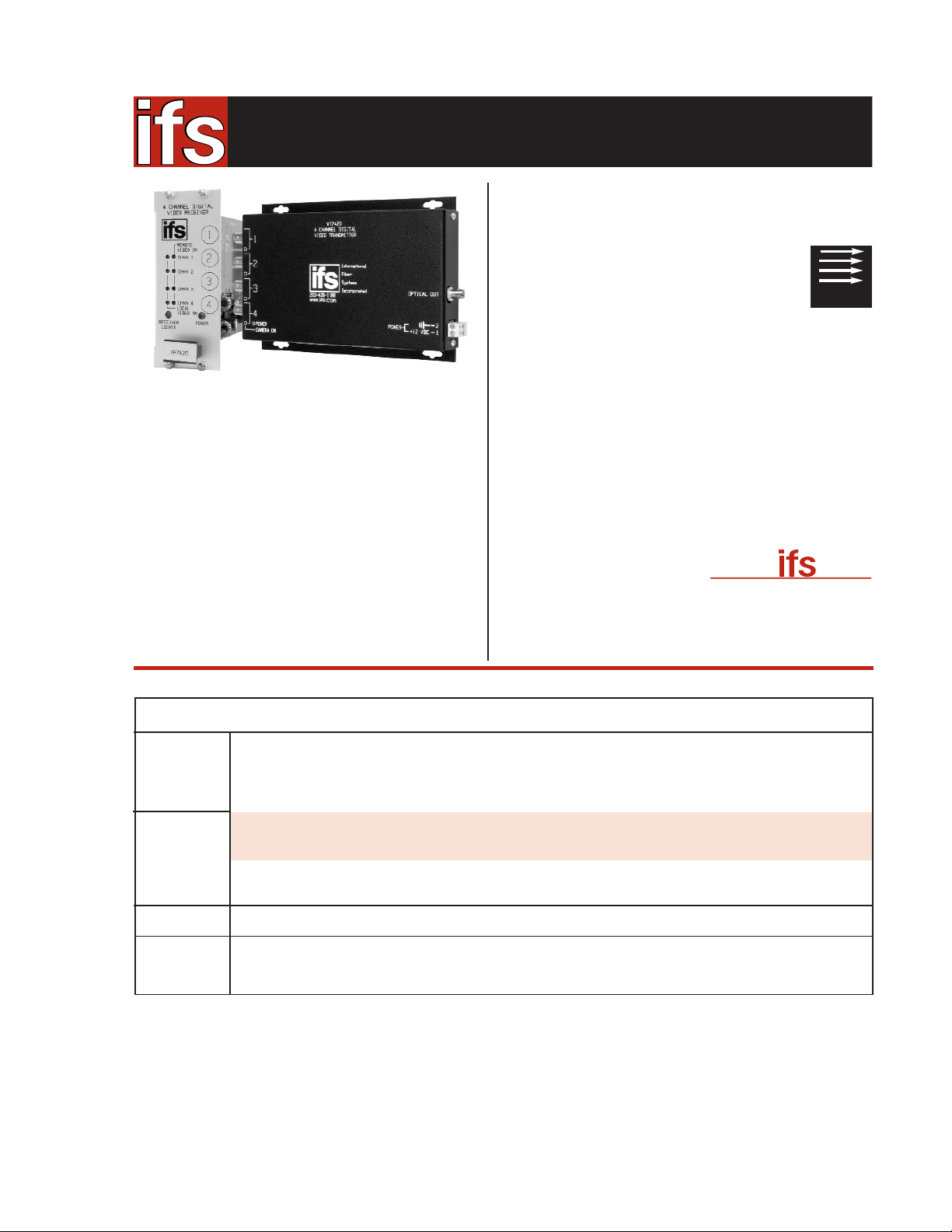
4 Channel Video Transmitter (1310 nm)
4 Channel Video Receiver (1310 nm)
4 Channel Video Transmitter (1310 nm)
4 Channel Video Transmitter (1310 nm)
4 Channel Video Receiver (1310 nm)
4 Channel Video Transmitter (1550 nm)
4 Channel Video Transmitter (1550 nm)
4 Channel Video Receiver (1550 nm)
4 Channel Video Transmitter (1310 nm)
4 Channel Video Receiver (1310 nm)
• 8-Bit Digitally Encoded Video Transmission Transmits
4 Real-Time Color Video Signals on One Optical Fiber
• Exceeds All Requirements for RS-250C Medium-Haul
Transmission: Extremely High Video Performance
• Exceptionally Low Video Distortion with Zero
Performance Variation vs. Optical Path Loss
• Ideally Suited to Networks Requiring Multiple
Physical Layers Where Video Degradation May be a Problem
• Compatible with all NTSC, PAL, or SECAM CCTV Camera Systems
• Wide Optical Dynamic Range: Optical Attenuators Are Never Required
• NTCIP Compatible
• Tested and Certified by an Independent Testing Laboratory for
Full Compliance with the Environmental Requirements (Ambient
Operating Temperature, Mechanical Shock, Vibration, Humidity
with Condensation, High-Line/Low-Line Voltage Conditions and
Transient Voltage Protection) of NEMA TS-1/TS-2 and the Caltrans
Specification for Traffic Signal Control Equipment.
• Robust Design Ensures Extremely High Reliability In
Unconditioned Out-of-Plant Environments
• LED Status Indicators Provide
Rapid Indication of Critical
Operating Parameters
• Solid-State Current Limiters on All
Power Lines Provide Equipment
Protection
• Comprehensive Lifetime Warranty
PRODUCT SPECIFICATION
4-CHANNEL DIGITALLY ENCODED VIDEO MULTIPLEXER
VT/VR7400 SERIES
FEATURES
• High-Performance CCTV (Fixed Video)
APPLICATION EXAMPLES
DESCRIPTION
The IFS VT/VR7400 series multiplexers simultaneously transmits
four channels of video over one optical fiber utilizing 8-bit digital
encoding for the high-quality video transmission. state-of-the-art 8-bit
digital encoding and decoding for high-quality video transmission that
exceeds the requirements of EIA RS-250C for Medium-Haul Video
Transmission. These environmentally hardened units are ideal for use
in unconditioned roadside or out-of-plant installations. These units are
completely transparent to and universally compatible with any NTSC,
PAL, or SECAM CCTV camera system. Plug-and-play design ensures
ease of installation and no electrical or optical adjustments are ever
required. LED indicators are provided for rapidly ascertaining equipment operating status, and these units are available in either standalone or rack mount configurations.
SINGLEMODE
9/125µm
MULTIMODE
62.5/125µm**
1
1
1
PS-12VDC 12 Volt DC Plug-in Power Supply (Included)
PS-12VDC-230 12 Volt DC Plug-in Power Supply, 230 VAC Input (Included if specified at time of order)
Add ‘-R3’ to Model Number for R3 Rack Mount - No Charge (Requires R3 Rack purchased separately)
Add ‘-C’ for Conformally Coated Printed Circuit Boards (Extra charge, consult factory)
Add ‘-SC’ for SC Connector (Single-mode equipment only)
Add -‘FC’ to model number for FC Optical Connector (Singlemode equipment only)
VT7420
VR7420
VT7430
VT7430-HP
VR7430
VT7450
VT7450-HP***
VR7450
VT7420-HP
VR7420-HP
10 dB
20 dB
26 dB
20 dB
27 dB
17 dB
DESCRIPTION
ORDERING INFORMATION
PAR T
NUMBER
OPTICAL
PWR BUDGET
MAX.
DISTANCE*
FIBERS
REQUIRED
V
.comwww.
Available at:
Available at:
• A & E Specifications, (CSI)
• AutoCAD Drawings
• Operation Manuals
• Technical Bulletins
67 miles (108 km)
* Optical transmission distance is limited to optical loss of the fiber and any additional loss introduced by connectors, splices and patch panels. Distance can also be limited by
fiber bandwidth. ** For 50/125 Fiber, subtract 4 dB from Optical Power Budget.
▲
This product may be used with 62.5µm graded index multimode fiber having a maximum
run length of 2 km and/or a maximum optical loss of 10 dB.
(1) When ordered with the Fiber Optic Auto Reversing Switch FOARSMM (-R3), the optical power will be factory adjusted to maintain a net optical power budget of 10 dB.
NOTE: All optical terminations need to be epoxy polished with a minimum back reflection of -30dB.
***VT7450-HP requires a minimum of 3dB loss to operate.
♦
All accessories are third party manufactured.
1.2 miles (2 km)
▲
38 miles (60 km)
48 miles (78 km)
50 miles (80 km)
1.2 miles (2 km)
▲
(1)
International Fiber Systems, Incorporated ■ DESIGN CENTER (888) 999-9IFS or (203) 426-1180 ■ FAX (203) 426-3326 ■ [email protected]
Europe, Middle East, Africa TEL +44(0) 1732 522 777
■ Asia Pacific TEL +65 6235 2661 ■ Latin America TEL (512) 477-8787
ACCESSORIES
♦
OPTIONS
Page 2
10/06/04
VR7420
VR7430
VR7450
VR7450
VT7420
VT7430
VT7430-HP
VT7450
VT7450-HP***
VT7420-HP
Multimode
62.5/125µm
**
Singlemode
9/125µm
1310 nm
1550 nm
10 dB
20 dB
26 dB
20 dB
27 dB
17 dB
1.2 miles (2 km)
▲
38 miles (60 km)
49 miles (78 km)
50 miles (80 km)
67 miles (108 km)
1.2 miles (2 km)
▲
(1)
MODEL
MODEL
International
Fiber
Systems
Incorporated
203.426.1180
International
Fiber
Systems
Incorporated
203.426.1180
SYSTEM DESIGN
VIDEO
Video Input: 1 volt pk-pk (75 ohms)
# Input/Output Channels: 4
Bandwidth (minimum): 10 Hz - 6.5 MHz
Differential Gain: <2%
Differential Phase: <0.7°
Tilt: <1%
Signal-to-Noise Ratio (SNR): 60 dB @ mMaximum Optical Loss Budget
OPTICAL EMITTER Laser Diode (all models)
WAVELENGTH 1310 nm, Multimode
1310 or 1550 nm, Singlemode
NUMBER OF FIBERS 1
LED INDICATORS
VT Transmitter Unit:
• Video Input Sync Presence for Each Video Channel
• Video Input Overload for Each Video Channel
• Optical Carrier Detect/ Link-Lock
• Operating Power
◆
REMOTE SENSING
• Closed with Carrier Detect, 24VAC/VDC @ 100 mA
CONNECTORS
Optical: ST, SC or FC (see ordering information)
Power: Terminal Block with Screw Clamps
Video: BNC (Gold Plated Center-Pin)
ELECTRICAL & MECHANICAL
Power:
Surface Mount: +12 VDC @ 500 mA
Rack: From Rack
Number of Rack Slots: 2
Current Protection: Automatic Resettable Solid-State Current
Limiters
Circuit Board: Meets IPC Standard
Size (in./cm.) (LxWxH)
Surface Mount VT: 7.0 x 4.9 x 1.0 in., 17.8 x 12.5 x 2.5 cm
All Others: 7.7 x 5.0 x 2.0 in., 19.6 x 12.7 x 5.1 cm
Shipping Weight: < 2 lbs./0.9 kg
ENVIRONMENTAL
MTBF: > 100,000 hours
Operating Temp: -40° C to +74° C
Storage Temp: -40° C to +85° C
Relative Humidity: 0% to 95% (non-condensing)*
* May be extended to condensation conditions by adding suffix ‘–C’ to model
number for conformal coating.
SPECIFICATIONS
16 Commerce Road
■ Newtown, CT 06470
Due to our continued effort to advance technology, product specifications are subject to change without notice.
TECHNICAL SPECIFICATION
4-CHANNEL DIGITALLY ENCODED VIDEO MULTIPLEXER
VT/VR7400 SERIES
OPTICAL POWER BUDGET
FIBER
WAVELENGTH
TRANSMITTER
RECEIVER
OPTICAL
PWR BUDGET
* Optical transmission distance is limited to optical loss of the fiber and any additional loss introduced by connectors, splices and patch panels.
Distance can also be limited by fiber bandwidth. ** For 50/125 Fiber, subtract 4 dB from Optical Power Budget.
▲
This product may be used with 62.5µ graded index multimode fiber having a maximum run length of 2 km and/or a maximum optical loss of 10 dB.
(1) When ordered with the Fiber Optic Auto Reversing Switch FOARSMM (-R3), the optical power will be factory adjusted to maintain a net optical power budget of 10 dB.
***VT7450-HP requires a minimum of 3dB loss to operate.
MAX.
DISTANCE*
AGENCY COMPLIANCE
MADE IN THE USA
Federal Supply Schedule
Contract No. GS-07F-0049M
Complies with FDA Performance Standard for Laser Products,
Title 21, Code of Federal Regulations, Subchapter J
VR Receiver Unit:
• Video Output Sync Presence for Each Video Channel
• Video Output Overload for Each Video Channel
• Optical Carrier Detect/ Link-Lock w/Solid State Relay
◆
• Operating Power
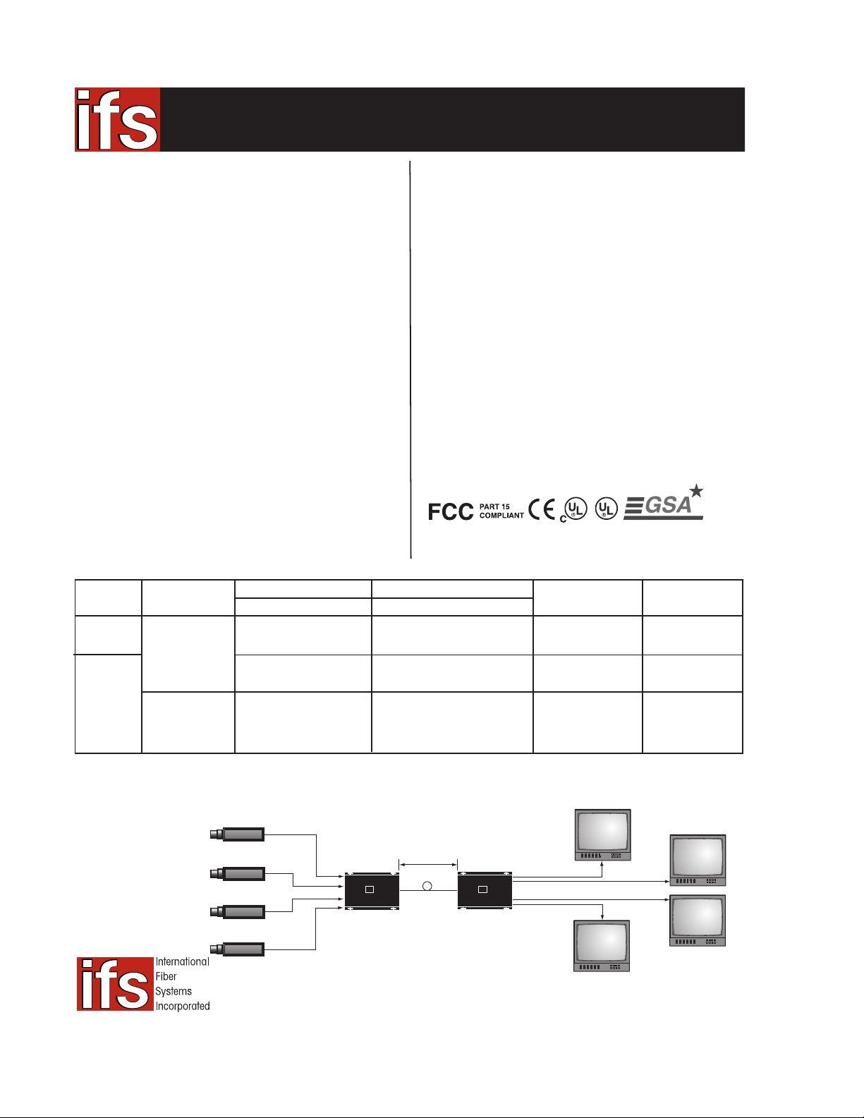
4 Video Inputs
VT7420
ifs
203.426.1180
International
Fiber
Systems
Incorporated
up to 1.2 miles
(2 km)
1 Fiber
62.5/125µm MM
VR7420
ifs
203.426.1180
International
Fiber
Systems
Incorporated
4 Video Outputs
 Loading...