

Page 1
GE
Table 1: Loop Resistance per 1000 feet
Wire Type Resistance
24 AWG /0,53 mm 52 ohms
23 AWG /0,57 mm 42 ohms
22 AWG /0,64 mm 33 ohms
Table 2: Power Distance Chart
Power Supply Voltage 12 VDC 24 VAC 28 VAC
Voltage at the Camera 10.8 VDC 21.6 VAC 21.6 VAC
Dual 24 AWG
448 ft. / 137 m 896 ft. / 273 m 2,388 ft. / 728 m
100 mA Camera
Dual 23 AWG
564 ft. / 172 m 1,130 ft. / 345 m 3,012 ft. / 918 m
Dual 24 AWG
150 ft. / 46 m 300 ft. / 92 m 796 ft. / 243 m
300 mA Camera
Dual 23 AWG
190 ft. / 58 m 378 ft. / 115 m 1,004 ft. / 306 m
Dual 24 AWG
46 ft. / 14 m 90 ft. / 28 m 240 ft. / 73 m
1 AMP Camera
Dual 23 AWG
58 ft. / 18 m 114 ft. / 35 m 300 ft. / 92 m
Introduction
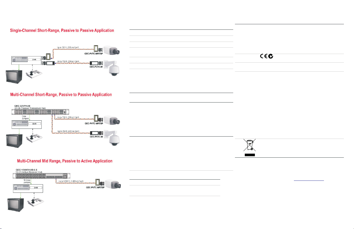
GE Security Single Channel Passive Transceivers transmit or receive base-band video signals over
point-to-point unshielded twisted pair (UTP) wires, category 2-7. They support distances up to 750 feet
(228 m) when they are used with any single or multi-channel GE passive transceiver and up to 3,500
feet (1,067 m) when used with a GE active transmitter. These transceivers are compact in size, easy to
install and do not require power. They also feature excellent crosstalk and noise immunity, which
ensures quality video up to the maximum distance.
All GE passive transceivers are bidirectional and support Up-the-Coax Pan/Tilt/Zoom telemetry signals.
Any unused pair of UTP cables can also be used for transporting other telemetry signals.
Models GEC-PVTC-MRTSP, GEC-PVTC-MCSP, GEC-PVTC-FCSP, and GEC-PVTC-MSP have built-in surge
suppression on the UTP input to protect video equipment against damaging voltage spikes.
The following model numbers are covered in this document:
•
GEC-1PVTC-F
• GEC-PVTC-M
• GEC-PVTC-MC
• GEC-PVTC-MRTSP
• GEC- PVTC-MCSP
•
GEC- PVTC-FCSP
• GEC- PVTC-MSP
Wiring Technical Notes
These technical notes should all be considered prior to installing these devices.
• Use point to point unshielded twisted pair wire 24-16 AWG (0, 5-1, 3 mm) stranded or solid,
Category 2 or better.
• The video signal may coexist in the same wire bundle as other video, telephone, data, control
signals, or low-voltage power. You can run GE Security video signals in or near electromagnetic
fields (in accordance with National Electrical Code, local or other local safety requirements).
• DO NOT USE SHIELDED TWISTED PAIR WIRE. Multi-pair (8 pair or more) wires with an overall shield
are fine.
• DO NOT USE UN-TWISTED WIRE.
• DO NOT place a transmit and a receive signal in the same wire bundle. It may cause interference.
• DO NOT send
Up-the-Coax
Pan/Tilt/Zoom signals through active (amplified) GE Security
transmitters or receivers. Passive GE Security transceivers can transmit video and
Up-the-Coax
P/T/Z control signals up to 750 ft. (228 m).
• We recommend using short 18 AWG solid wires for ground connections when applicable.
• GE Security VPD products follow the EIA/TIA 568 standard. There are two wire color-code
standards: EIA/TIA 568A and EIA/TIA 568B. Either standard can be used for making connections as
long as the RJ-45 jacks at both ends of each cable follow the same standard.
• Measure wire distance by:
1. Shorting the two conductors together at the far end, and measuring the loop-resistance
by an Ohmmeter.
2. Use the
Loop Resistance
table to calculate the distance.
• DO NOT connect coax cables longer than 100 ft. (30 M) to the BNC connectors of any GE Security
UTP equipment.
• All measured distances should include any coax cables in the path.
• Verify camera current requirement and wire resistance limits for the maximum distance that
power can travel. Use the
Power Distance Chart
to verify the wire distance.
• GE Security VPD products require Unshielded Twisted-Pair (UTP) wires Category 2 or better, 24
AWG (0,5 mm) or thicker.
Camera End Installation
UTP:
• Connect the UTP wire to the terminal block of the passive transceiver. Make sure to observe the
color-coding of the selected pair and its polarity. It is necessary to use the same pair and polarity
on the receiving end.
• If the camera has a qualified built-in UTP transceiver, connect the UTP wire directly to the UTP
connector of the camera.
Video:
• Connect the baseband Video signal output of the camera to the BNC connector of the transceiver.
Ground (GEC-PVTC-FCSP and GEC-PVTC-MSP only):
• Connect the ground screw connector to a qualified earth ground using a short thick wire.
Control Room Installation
UTP:
• Connect the UTP wires carrying the video signals to the terminal block input of the transceiver.
• Make sure that the same UTP pair and polarity are used on both the transmit and receiver sides.
Video:
• Connect the passive transceiver’s BNC output to the baseband video input of a video receiver such
as a matrix switch, a DVR or a monitor.
• Make sure that the same UTP pair and polarity are used on both the transmit and receiver sides.
• Confirm that the device receiving video is terminated with a single 75 ohm terminator.
Ground (GEC-PVTC-FCSP and GEC-PVTC-MSP only):
• Connect the ground screw connector to a qualified earth ground using a short thick wire.
• If the picture is scrambled change the polarity of the twisted pair wires of the corresponding
terminal block.
Security
P/N 1069687 REV 1.1 ISS 28APR10
Single-Channel Passive Transceiver Installation Sheet
GEC-1PVTC-F GEC-PVTC-M GEC-PVTC-MC GEC-PVTC-MRTSP GEC-PVTC-MCSP GEC-PVTC-FCSP GEC-PVTC-MSP
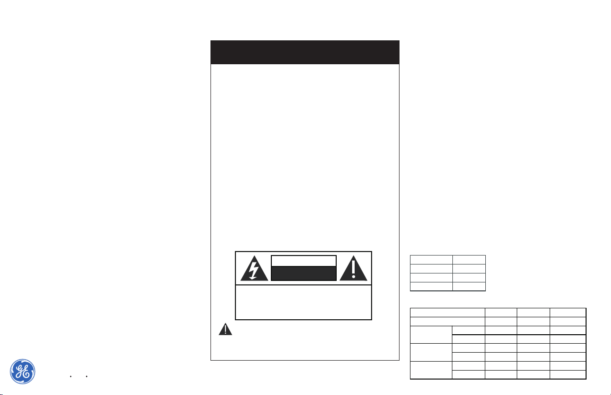
IMPORTANT SAFETY INSTRUCTIONS
IMPORTANT SAFETY INSTRUCTIONS
1) Read these instructions.
2) Keep these instructions.
3) Heed all warnings.
4) Follow all instructions.
5) Do not use this apparatus near water.
6) Clean only with a dry cloth.
7) Do not block any ventilation openings.
8) Install in accordance with the manufacturer’s instructions.
9) Do not install near any heat sources such as radiators, heat
registers, stoves or other apparatus (including DVRs) that produce
heat.
10) Only use attachments/accessories specified by the
manufacturer.
11) Refer all servicing to qualified service personnel. Servicing is
required when the apparatus has been damaged in any way, such
as a power supply cord or plug is damaged, liquid has been
spilled, or objects have fallen into the apparatus, the apparatus
has been exposed to rain or moisture, does not operate normally,
or has been dropped.
CAUTION
RISK OF ELECTRIC SHOCK
CAUTION: TO REDUCE THE RISK OF ELECTRICAL SHOCK,
DO NOT REMOVE COVER. NO USER SERVICEABLE
PARTS INSIDE. REFER SERVICING TO QUALIFIED
SERVICE PERSONNEL.
WARNING! - To reduce the risk of fire or electric shock,
do not expose this apparatus to rain or moisture. This apparatus
shall not be exposed to dripping or splashing and no objects
filled with liquids, such as vases shall be placed on the apparatus.
DO NOT OPEN
Page 2
Technical Specifications*
Electrical
Video Format NTSC, PAL, SECAM
Frequency 20 to 10 MHz
Coax 75 Ohm
Twisted Pair 100 Ohms +/- 20%, 24 AWG MINIMUM Category 2-7 up to
750 ft. (228 m)
Power No power required
CMRR 60 dB
Connectors
UTP
: Screw terminal blocks or screw-less connectors
Video Outputs:
BNC connector
GND:
Ground screw
Mechanical
Material ABS plastic, UL rating of 94V-0 41 (excluding GEC-1PVTC-F
and GEC-PVTC-M)
Dimensions (W x H x D)
GEC-1PVTC-F:
0.63 x 0.60 x 1.82 in. (1.6 x 1.5 x 4.7 cm)
GEC-PVTC-M:
0.63 x 0.60 x 1.82 in. (1.6 x 1.5 x 4.7 cm)
GEC-PVTC-MC:
0.54 x 0.54 x 1.85 in. (1.4 x 1.4 x 4.7 cm)
GEC-PVTC-MRTSP:
0.94 x 0.55 x 1.26 in. (2.4 x 1.4 x 3.2 cm)
GEC- PVTC-MCSP:
0.54 x 0.54 x 1.85 in. (1.4 x 1.4 x 4.7 cm)
GEC- PVTC-FCSP:
0.54 x 0.54 x 1.85 in. (1.4 x 1.4 x 4.7 cm)
GEC- PVTC-MSP:
0.54 x 0.54 x 1.85 in. (1.4 x 1.4 x 4.7 cm)
Weight
GEC-1PVTC-F:
0.04 lb. (18 g)
GEC-PVTC-M:
0.04 lb. (18 g)
GEC-PVTC-MC:
0.06 lb. (26 g)
GEC-PVTC-MRTSP:
0.04 lb. (18 g)
GEC- PVTC-MCSP:
0.06 lb. (26 g)
GEC- PVTC-FCSP:
0.04 lb. (18 g)
GEC- PVTC-MSP:
0.04 lb. (18 g)
Environmental
Humidity 0 to 95%, noncondensing
Temperature Operating: -10° C to +50° C
Storage: -30° C to +70° C
*Specifications are subject to change without notice.
Regulatory information
Manufacturer GE Security, Inc.
HQ and regulatory responsibility:
GE Security, Inc., 8985 Town Center Parkway,
Bradenton, FL 34202, USA
EU authorized manufacturing representative:
GE Security B.V., Kelvinstraat 7,
6003 DH Weert, The Netherlands
Regulatory
information
N4131
North American
standards
UL 60065
FCC Compliance This equipment has been tested and found to comply with the limits for a
Class B digital device, pursuant to part 15 of the FCC Rules. These limits
are designed to provide reasonable protection against harmful
interference in a residential installation. This equipment generates, uses
and can radiate radio frequency energy and, if not installed and used in
accordance with the instructions, may cause harmful interference to
radio communications. However, there is no guarant ee that interference
will not occur in a particular installation. If this equipment does cause
harmful interference to radio or television reception, which can be
determined by turning the equipment off and on, the user is encouraged
to try to correct the interference by one or more of the following
measures:
• Reorient or relocate the receiving antenna.
• Increase the separation between the equipment and receiver.
• Connect the equipment into an outlet on a circuit different from that
to which the receiver is connected.
• Consult the dealer or an experienced radio/TV technician for help.
2002/96/EC (WEEE directive): Products marked with this symbol cannot be
disposed of as unsorted municipal waste in the European Union. For
proper recycling, return this product to your local supplier upon the
purchase of equivalent new equipment, or dispose of it at designated
collection points. For more information see: www.recyclethis.info.
Application Diagrams
Contact information
For co ntact informati on s ee our Web site: www .gesecur ity. com.
For co ntact informati on s ee our Web site: www .gesecur ity. eu.
 Loading...