

Page 1

VIC5211M
VIC5211M-R3
VIC5211R
IFS Fiber Module
Installation & Operation
Instructions
P/N 1062823 • REV B • ISS 01JUL11
Page 2
SPEAKER VOLUME
NOTE: WITHOUT PROPER FIBER
CONNECTION, LED's DO NOT
INDICATE CORRECT
OPERATIONAL STATUS OF
THE UNIT.
MICROPHONE GAIN
AGC
POWER
ifs
VIC5211M
VIDEO INTERCOM MASTER
International
Fiber
Systems
Incorporated
OPTICAL
CABLE
REMOTE RELAY CONTROL- 6
SPEAKER
CALL BUTTON
VIDEO OUT
24 VAC
CENTER
TAPPED
AC - 3
AC- 1
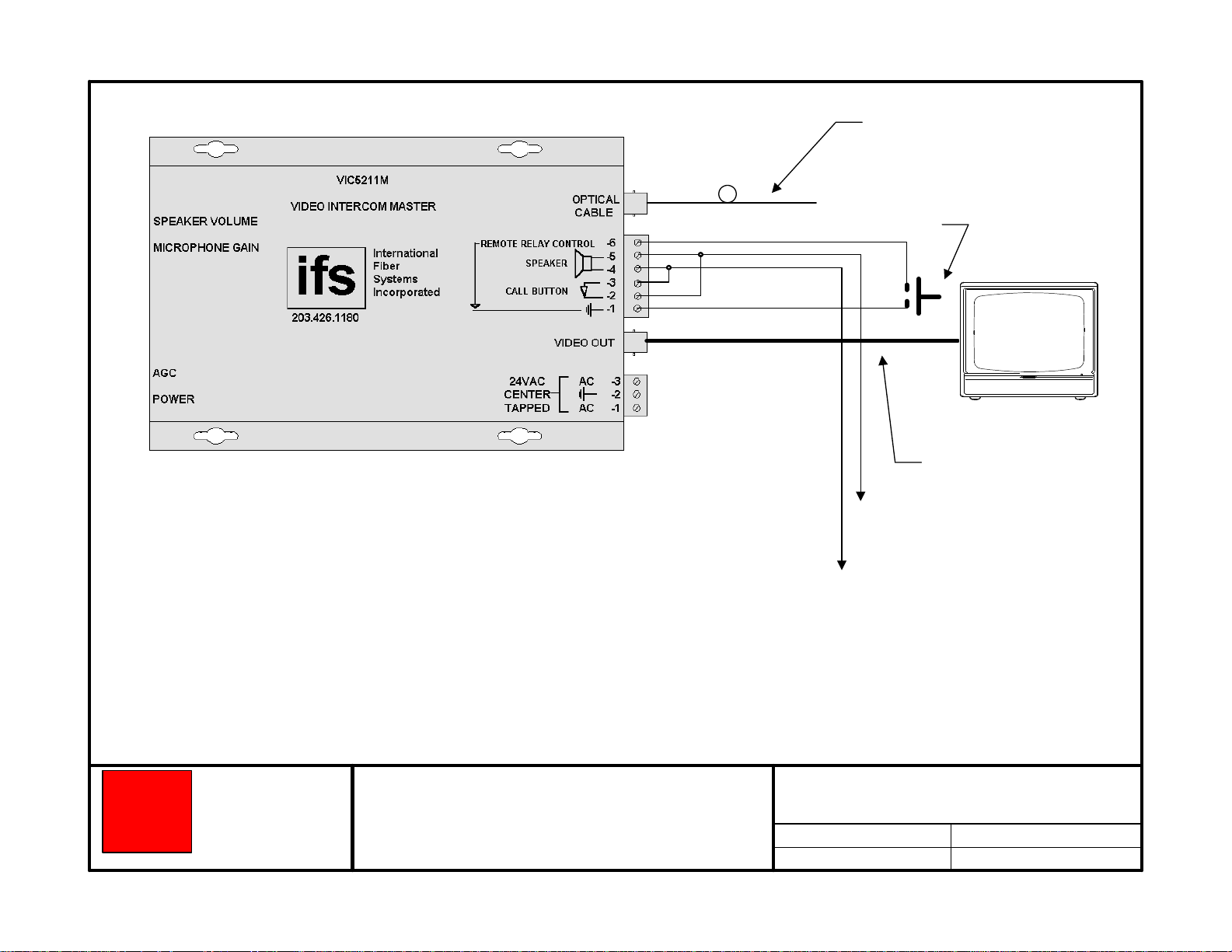
1 2 - N.C. 18 VAC @ 16VA
3 -
Simplex multimode
fiber optic cable
- 5
- 4
- 3
- 2
- 1
- 2
Blue
Green
Brown
Coax cable
Video
monitor
SPEAKER VOLUME
VIC5211R
VIDEO INTERCOM REMOTE
Video Source
Coax cable
1 -
SPEAKER
2 3 - GRD
4 -
CALL BUTTON
5 6 -
RELAY
7 -
POWER
CARRIER DETECT
VIDEO INPUT
MICROPHONE VOLUME
ifs
International
Fiber
Systems
Incorporated
OPTICAL CABLE
Page 3
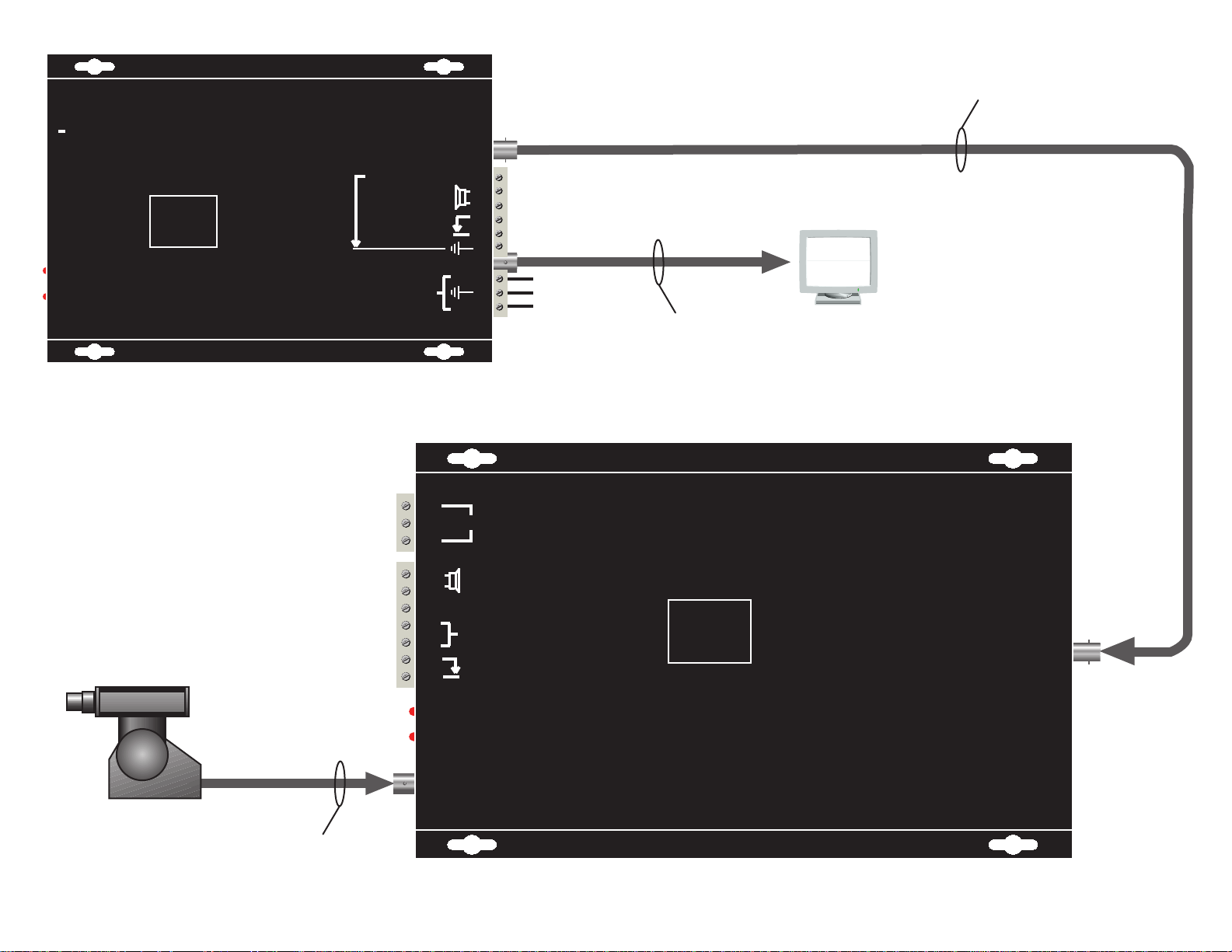
one 62.5/ 125 µ multimode
fiber to VIC5211R
gate release, typ.
to LEM or
LEF "E"
MONITOR
coaxial cable to monitor
to LEM or
LEF station
NOTE: The shorting bracket connecting "E" and "-" on the LEF MUST be in place. (1, 2, 3, ...)
Researched by the IFS Technical Support Group this drawing was assembled and at
the time of publication is believed to be accurate. This information is the property of IFS
and is subject to change at any time. For the current release of this dra wing contact the
Drawing Number
Release Date
IFS Technical Support Group at 1 888 999 9437
Or visit the IFS web site at www.IFS.com
ifs
International
Fiber
Systems
Incorporated
DRAWING NAME
Connections between an Aiphone LEM or LEF
master station and an IFS VIC5211M
video intercom master
Revision
Revision Date
Page 4
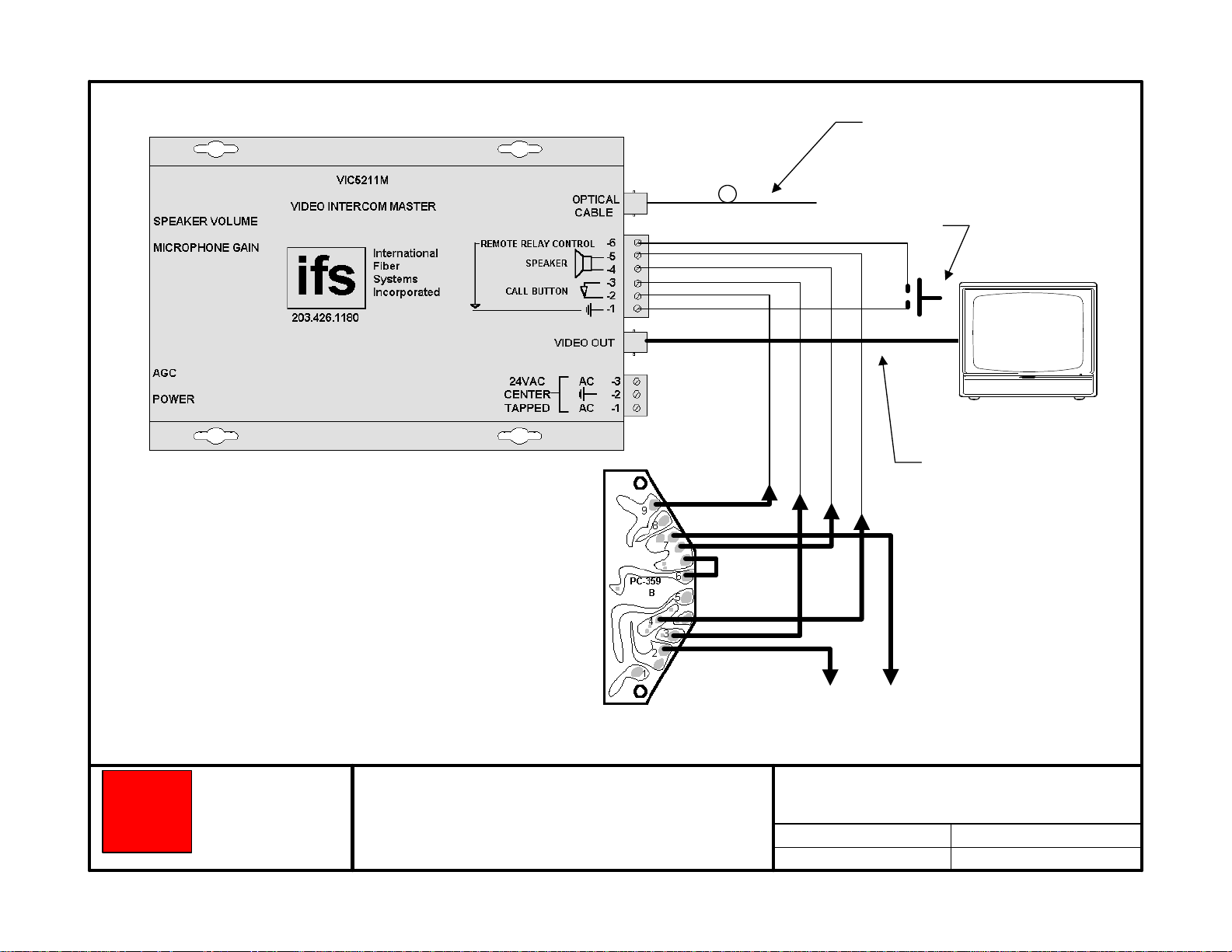
one 62.5/ 125 µ multimode
fiber to VIC5211R
gate release, typ.
MONITOR
coaxial cable to monitor
ifs
International
Fiber
Systems
Incorporated
to NEM master 1 - 40
DRAWING NAME
Connections between an Aiphone NEM master
station, an Aiphone PC-359B call latching board,
and an IFS VIC5211M video intercom master
to NEM master "E"
Researched by the IFS Technical Support Group this drawing was assembled and at
the time of publication is believed to be accurate. This information is the property of IFS
and is subject to change at any time. For the current release of this dra wing contact the
Drawing Number
Release Date
IFS Technical Support Group at 1 888 999 9437
Or visit the IFS web site at www.IFS.com
Revision
Revision Date
Page 5

to pin 2
9
4
2
8
7
3
6
5
to pin 3
to pin 4
connections to
VIC5211M
to pin 5
ifs
1
International
Fiber
Systems
Incorporated
to NEM master
1 - 40
DRAWING NAME
Expanded view of the Aiphone PC-359B call
latching board with connections to an Aiphone
NEM master station and an IFS VIC5211M
video intercom master
to NEM master
"E"
Researched by the IFS Technical Support Group this drawing was assembled and at
the time of publication is believed to be accurate. This information is the property of IFS
and is subject to change at any time. For the current release of this dra wing contact the
Drawing Number
Release Date
IFS Technical Support Group at 1 888 999 9437
Or visit the IFS web site at www.IFS.com
Revision
Revision Date
Page 6

to LE-D
pin "-"
CCTV camera
Aiphone LE-D series
door station
to LE-D
pin "E"
to LE-D
pin "1"
shorting bracket
connecting "E" and "-"
must be removed
18 VAC
ifs
International
Fiber
Systems
Incorporated
coaxial cable to camera
DRAWING NAME
Connections between an Aiphone LE-D
series door station and an IFS VIC5211R
video intercom remote
one 62.5/ 125 µ multimode
fiber to VIC5211M
Researched by the IFS Technical Support Group this drawing was assembled and at
the time of publication is believed to be accurate. This information is the property of IFS
and is subject to change at any time. For the current release of this dra wing contact the
Drawing Number
Release Date
IFS Technical Support Group at 1 888 999 9437
Or visit the IFS web site at www.IFS.com
Revision
Revision Date
Page 7

normally-open
momentary push button
CCTV camera
20-ohm speaker
coaxial cable to camera
18 VAC
one 62.5/ 125 µ multimode
fiber to VIC5211M
ifs
International
Fiber
Systems
Incorporated
DRAWING NAME
Connections between a 20-ohm speaker, a
normally-open, momentary push button, and an
IFS VIC5211R video intercom remote
Researched by the IFS Technical Support Group this drawing was assembled and at
the time of publication is believed to be accurate. This information is the property of IFS
and is subject to change at any time. For the current release of this dra wing contact the
Drawing Number
Release Date
IFS Technical Support Group at 1 888 999 9437
Or visit the IFS web site at www.IFS.com
Revision
Revision Date
Page 8

FCC Compliance
This device complies with Part 15 of the FCC Rules. Operation is subject to the following two
conditions: (1) This device may not cause harmful interference, and (2) this device must accept
any interference received, including interference that may cause undesirable operation.
Changes or modifications not expressly approved by International Fiber Systems, Inc. could void
the user’s authority to operate the equipment.
NOTE: This equipment has been tested and found to comply with the limits for a Class A
digital device, pursuant to Part 15 of the FCC Rules. These limits are designed to provide
reasonable protection against harmful interference when the equipment is operated in a
commercial environment. This equipment generates, uses and can radiate radio frequency
energy and, if not installed and used in accordance with the instruction manual, may cause
harmful interference to radio communications. Operation of this equipment in a residential
area is likely to cause harmful interference in which case the user will be required to correct the
interference at his own expense.
CLASS 1 LASER PRODUCT
(For purposes of IEC 60825-1)
Complies with FDA Performance Standard for Laser Products
Title 21
Code of Federal Regulations
Subchapter J
Comprehensive
Lifetime Warranty
(a) Seller warrants to the original End User that products and any
services furnished hereunder will be free from defects in material
and workmanship as of the date of delivery, and will conform to
Seller’s published technical specications. The foregoing shall
apply only to failures to meet said warranties which appear within
that period of time during which the Products are installed in their
original installation for the original End User and operator of such
Products; provided, however, that in the event of product discontinuance, warranty support is limited to ve (5) years from the
announcement of discontinuance. Notwithstanding the preceding
sentence, the duration of the warranty period for
manufactured by Seller (e.g., ber optic cabling, test equipment,
power supplies or batteries) shall be the warranty period oered by
the original manufacturer, if any.
(b) The conditions of any tests shall be mutually agreed upon and
Seller shall be notied of, and may be represented at, all tests that
may be made. The warranties and remedies set forth herein are
conditioned upon (a) proper storage, installation, use and maintenance, and conformance with
Seller and (b) Buyer promptly notifying Seller of any defects and,
if required, promptly making the product available for correction.
(c) If any product or service fails to meet the foregoing warranties,
Seller shall thereupon correct any such failure either at its option,
any applicable recommendations of
products not
(i) by repairing any defective or damaged product or parts of the
products, or (ii) by making available any necessary repaired or
replacement products or parts thereof. Any repaired or replacement
part or product shall be warranted for the remaining period of the
original Warranty Period. Seller shall pay, or credit Buyer for, the
cost of freight for all return shipments of products or parts to
Buyer. Where a failure cannot be corrected by Seller's reasonable
eorts, the parties will negotiate an equitable adjustment in price.
(d) The preceding paragraph sets forth the exclusive remedies for
claims based on defect in or failure of products or services,
whether the claim is in contract, indemnity, warranty, tort
(including Seller's negligence), strict liability or otherwise and
however instituted. Upon the expiration of the warranty period,
all such liability shall terminate and BUYER shall have a reason-
time, within thirty days after the warranty period, to give
able
written notice of any defects which appeared during the warranty
period. The foregoing warranties are exclusive and in lieu of all
other warranties, whether written, oral, implied or statutory.
NO IMPLIED OR STATUTORY WARRANTY OF
MERCHANTABILITY OR FITNESS FOR PARTICULAR
PURPOSE SHALL APPLY. Seller does not warrant any
products or services of others which BUYER has designated.
Page 9
Contacting us
For help installing, operating, maintaining, and troubleshooting this product, refer to this document and any
other documentation provided. If you still have questions, contact us during business hours (Monday through
Friday, excluding holidays, between 5 a.m. and 5 p.m. Pacific Time).
Sales and support contact information
North
America
Toll-free: 855.286.8889 in the US, including Alaska and Hawaii;
Puerto Rico; Canada.
Outside the toll-free area: 503.885.5700.
E-mail: techsupport@interlogix.com
Europe
Australia
Select Contact Us at www.utcfssecurityproducts.eu
security.tech.support@interlogix.com.au
Note: Be ready at the equipment before calling.
Online
Another great resource for assistance with your Interlogix product is our online publication library. To access
the library, go to our website at the following location:
http://www.interlogix.com/transmission
1
1. Many Interlogix documents are provided as PDFs (portable document format). To read these documents, you will
need Adobe Reader, which can be downloaded free from Adobe’s website at www.adobe.com.
Page 10

Product Disassembly Instructions for WEEE
Per European Directive 2002/95/EC Waste Electrical and
Electronic Equipment
Required Tools:
One number 2 Phillips (crosstip) screwdriver.
One number 2 flat screwdriver.
For the enclosed box version:
1. Locate and remove box cover securement screws. Usually, but not limited to, at least
4 screws.
2. Lift off box top cover.
3. Locate and remove securement screws for printed circuit board.
4. If there are multiple boards to the assembly, continue removing securement screws
until none are left.
5. Lift off printed circuit board.
6. Disassembly of box version of product is complete.
For rack version:
1. Locate and remove securement screws for printed circuit board. Usually, but not
limited to, at least 4 screws.
2. If there are multiple boards to the assembly, continue removing securement screws
until none are left.
3. Lift off printed circuit board(s).
4. Disassembly of rack card version of product is complete.
Page 11

Copyright © 2011 UTC Fire & Security. All rights reserved.
r
Trademarks and
patents
Manufacture
Certification
ACMA compliance Notice! Thi
Canada This Class A digital apparatus complies with Canadian ICES-003.
European Union
directives
Interlogix and IFS names and logos are trademarks of
UTC Fire & Security.
Other trade names used in this document may be trademarks or
registered trademarks of the manufacturers or vendors of the
respective products.
UTC Fire & Security Americas Corporation, Inc.
2955 Red Hill Avenue, Costa Mesa, CA 92626-5923, USA
Authorized EU manufacturing representative:
UTC Fire & Security B.V.
Kelvinstraat 7, 6003 DH Weert, The Netherlands
N4131
product may cause radio interference in which case the user may be
required to take adequate measures.
Cet appareil numérique de la classe A est conforme à la norme
NMB-0
2004/108/EC (EMC directive): Hereby, UTC Fire & Security
decl
requirements and other relevant provisions of Directive
2004/108/EC.
03 du Canada.
ares that this device is in compliance with the essential
s is a Class A product. In a domestic environment this
2002/96/EC (WEEE directive): Products marked with this symbol
cannot be disposed of as unsorted municipal waste in the European
Union. For proper recycling, return this product to your local supplier
upon the purchase of equivalent new equipment, or dispose of it at
designated collection points. For more information see:
www.recyclethis.info.
Contact information For contact information, see www.interlogix.com.
 Loading...