

Page 1
VE1120 Series PIR Detector Installation Sheet
)
EN DA DE ES FI FR IT NL NO PL PT SV
1
3
2
(1)
(3)
4
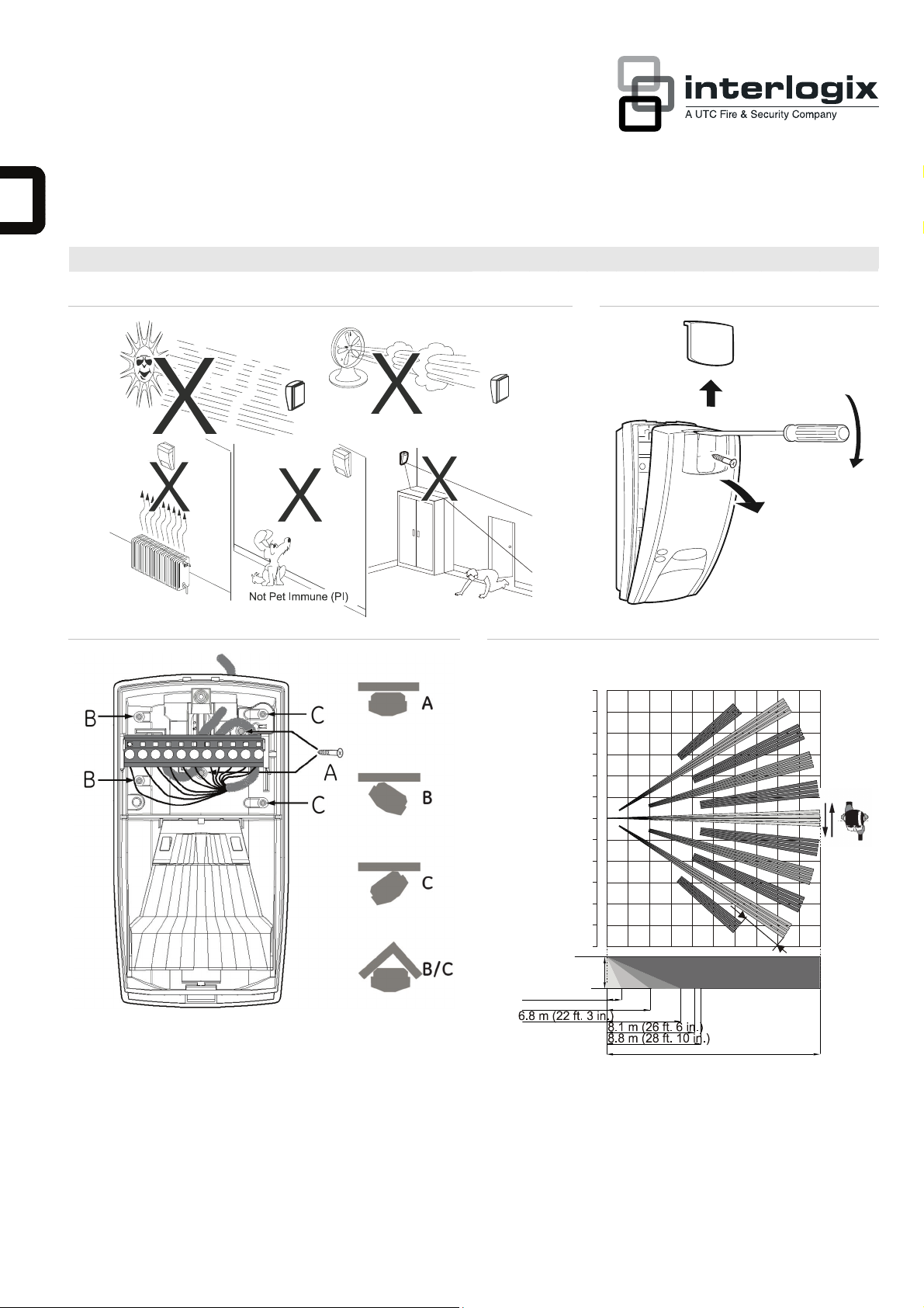
20 m range (65 ft. 7 in.)
12 m (39 ft. 4 in.)
10 m (32 ft. 9 in.)
8 m (26 ft. 2 in.)
6 m (19 ft. 8 in.)
4 m (13 ft. 1 in.)
2 m (6 ft. 6 in.)
0 m
2 m (6 ft. 6 in.)
4 m (13 ft. 1 in.)
6 m (19 ft. 8 in.)
8 m (26 ft. 2 in.)
10 m (32 ft. 9 in.)
12 m (39 ft. 4 in.)
(optimum) 2.4 m
(7 ft. 10 in.)
1.2 m (3 ft. 11 in.)
4 m (13 ft. 1 in.)
4
m
(2)
20.0 m (65 ft. 7 in.
© 2012 UTC Fire & Security. All rights reserved. 1 / 32 P/N 146279999-2 (ML) • REV C • ISS 28JUN12
Page 2
5
1120
1120
VE
VE
AM
J4
J3
J6
6
J1
J4
J3
J6
J1
J1: Not used
J3 and J4: See Figure 7.
J6:
CV + polarity
CV – polarity
2 / 32 P/N 146279999-2 (ML) • REV C • ISS 28JUN12
Page 3
7
(1)
(2)
VE1120 VE1120AM
GND
+12V
Alarm
Alarm
Ta m p e r
Tamper
4
567
WT
D/N
8
J4
J3
123
CP
Normal
< 33 Ω
larmA
8
Zone X
VE1120 VE1120AM
J4
J3
CP
Normal
larmA
Ta mp er
Short
4.7 k
9.4
8
0
Ω
GND
+12V
123
Ω
kΩ
Alarm
Alarm
Ta m p e r
Tamper
567
4
Zone X
WT
D/N
8
J3
J3
J4
J4
GND
+12V
123
GND
+12V
123
Alarm
Alarm
Ta m p e r
Ta m p e r
WT
D/N
J4
567
8
4
Alarm
Alarm
Ta m p e r
Tamper
567
4
WT
J3
CP
D/ND/N
8
Normal
larmA
Tam p er
Short
AM/TF
J4
J3
CP
Normal
4.7 k
9.4
88
0
Ω
Alarm
4
Zone X
Rtest
11
WT
D/N
AM
Ta m p e r
Ta m p e r
5
6
AM
Rtest
7
9
8
11
10
Zone Y
Alarm
3
Alarm
3
WT
D/N
Tamper
5
6
Ta m p e r
5
AM
Ta m p e r
AM
Rtest
7
9
8
11
10
WT
D/N
AM
Ta m p e r
AM
Rtest
7
9
8
6
11
10
Alarm
4
Alarm
4
J3
J4
J4
J3
GND
+12V
2
1
GND
+12V
2
1
GND
+12V
Alarm
2
3
1
< 33 Ω
larmA
8
GND
+12V
2
1
Ω
kΩ
WT
Alarm
D/N
Ta m p e r
5
Zone X
AM
AM
Ta m p e r
7
9
8
6
10
Zone Y
Alarm
3
4
J4
J3
Normal
Tam p er
Short
GND
+12V
Alarm
Alarm
Ta m p e r
Ta m p e r
WT
567
123
4
4.7 k
9.4
0
Ω
kΩ
Zone X
8
Ω
larmA
EN: Installation Sheet
Introduction
The VE1120 series includes the VE1120 PIR and VE1120AM
PIR-AM motion sensors. They have a patented mirror, pyro,
and signal processing technology.
Note: VE1120AM has not been evaluated by UL/cUL.
Installation guidelines
The technology used in these detectors resists false alarm
hazards. However, avoid potential causes of instability (see
Figure 1) such as:
• Direct sunlight on the detector
• Strong draughts onto the detector
• Heat sources within the detector field of view
• Animals within the detector field of view
• Obscuring the detector field of view with large objects,
such as furniture
• Objects within 50 cm (20 in.) of the anti-masking (AM)
detector
Alarm
3
WT
D/N
Alarm
4
AM
Ta m p e r
Tamper
5
AM
Rtest
7
9
8
6
11
10
GND
8
J4
J3
+12V
2
1
CP
Normal
4.7 k
9.4
0
Ω
kΩ
88
Zone X
Ω
Zone Y
larmA
Tamper
Short
AM/TF
• Installing two detectors facing each other and less than
50 cm (20 in.) apart (only AM detectors)
Installing the detector
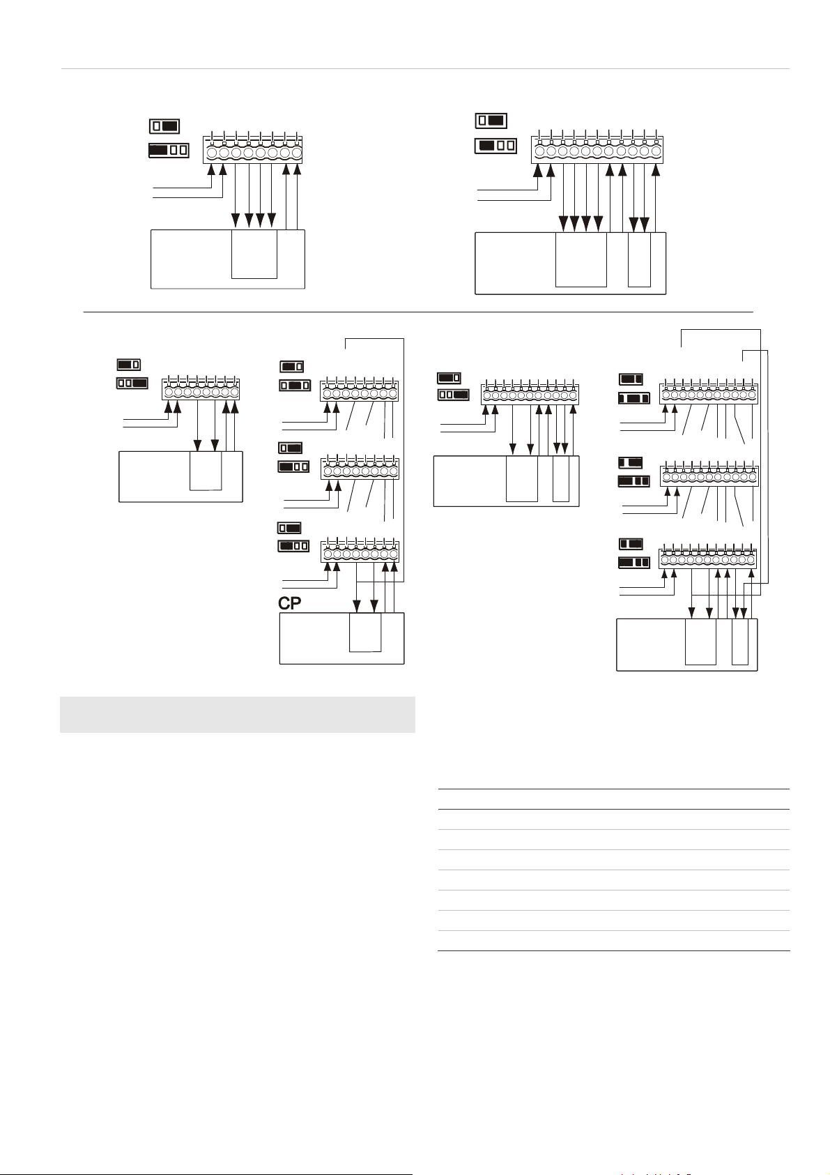
Figure 7 legend
Item Description
(1) Standard connection (factory default)
(2) Dual loop connection
CP Control panel
WT Walk test
AM Antimasking
D/N Day/night
Rtest Remote test
To install the detector:
1. Lift off the custom insert and remove the screw
(see Figure 2, step 1).
2. Using a screwdriver, carefully prise open the detector (see
Figure 2, steps 2 and 3).
3. Fix the base to the wall between 1.8 and 3.0 m (5.9 and
9.8 ft.) from the floor. For flat mounting use a minimum of
P/N 146279999-2 (ML) • REV C • ISS 28JUN12 3 / 32
Page 4

two screws (DIN 7998) in positions A. For corner-mounting
use screws in positions B or C (Figure 3). To install a pryoff tamper, use position A or C.
Note: Using the pry-off tamper has not been evaluated by
UL/cUL.
4. Wire the detector (see Figures 3 and 7).
UL/cUL installations: All wiring must be made according
to National Electrical Code, NFPA70, and CSA C22.1,
Canadian Electrical Code Part I, Safety Standards for
Electrical Installations.
5. Select the desired jumper and DIP switch settings (see
Figure 5). See “Jumper settings” below for more
information.
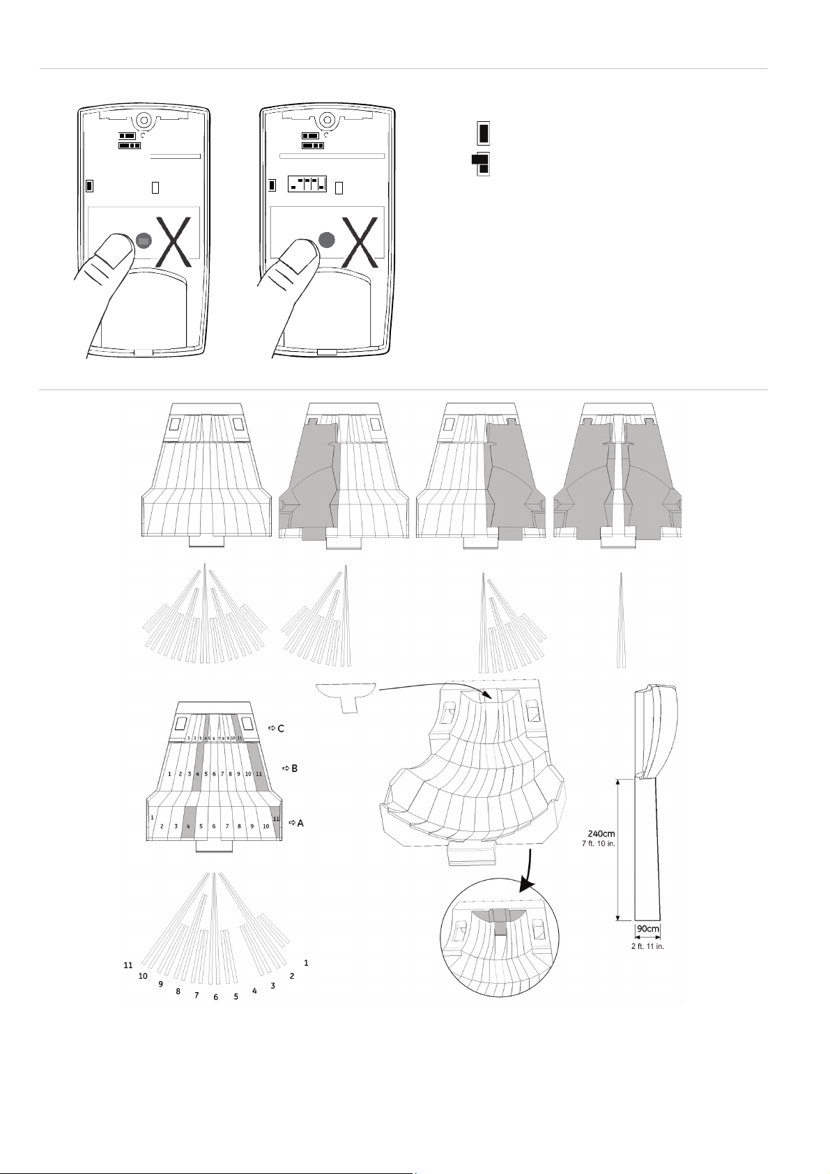
Remove the blinders and add the stickers, if required (see
6.
Figure 6 for an example).
7. For ceiling-mount applications that require a 90° coverage
use the SB01 swivel-mount bracket.
Note: Using the swivel-mount bracket has not been
evaluated by UL/cUL. Ceiling mount application has not
been evaluated by UL/cUL.
8. Close the cover.
9. Insert the screw and place the custom insert.
For EN 50131 Grade 3 installations, do not use mounting
position B.
Jumper settings
See Figure 5 for the jumper locations in the detector.
J1: Not used
J3 and J4: Dual loop setting
This sets the alarm and tamper relays. It allows you to connect
the detector to any control panel. Use jumpers 3 and 4. See
Figure 7.
Use Remote Test (RT) to test the detector from the control
panel. The detector will activate the Alarm relay if the test
result is positive, and the AM relay if the test result is negative.
J6: Polarity setting of the control voltage (CV)
On (factory default):
• The detector is in Day mode (system disarmed) when the
D/N input is connected to GND (terminal 1)
• The detector is in Night mode (system armed) when the
D/N input is connected to +12 V (terminal 2)
• The detector is in Walk Test Off mode (LEDs are disabled)
when the WT input is connected to GND (terminal 1)
• The detector is on Walk Test On mode (LEDs are
enabled) when the WT input is connected to +12 V
(terminal 2)
Off:
• The detector is in Day mode (system disarmed) when the
D/N input is connected to +12 V (screw terminal 2).
• The detector is in Night mode (system armed) when the
D/N input is connected to GND (terminal 1).
• The detector is in Walk Test Off mode (LEDs are disabled)
when the WT input is connected to +12 V (terminal 2).
• The detector is on Walk Test On mode (LEDs are
enabled) when the WT input is connected to GND
(terminal 1).
D/N and WT functionality
The D/N input:
• Controls the LED functionality together with the WT input.
• Resets the alarm memory
• Controls the AM relay functionality during the NIGHT
mode together with SW1.
The WT input controls the LED functionality together with the
D/N input.
When the detector is in the Day mode and Walk Test On
mode, the LEDs of the detector can be activated. See “
ation” below for more information.
indic
LED
During the Night mode the LEDs are always switched off.
If a PIR intruder alarm if detected in the Night mode and the
detector switches back to Day mode, the red LED starts
flashing to indicate an alarm in memory.
The alarm memory is reset by switching the detector to Night
mode.
DIP switch settings
Factory default:
54321
ON
SW 1: When to signal AM (anti-masking) or TF (technical
fault) output
On: Signals AM or TF only when the system is in Day mode
(factory default).
Off: Always signals AM or TF during Day and Night mode.
SW 2: AM sensitivity
On: Selects a higher level of AM sensitivity. AM relay reacts
within 6 seconds.
Off: Selects the standard AM sensitivity. AM relay reacts within
12 seconds (factory default).
SW 3: Resetting the AM/TF output
The system will only reset an AM alarm if it has ensured that
the cause of the AM alarm has been removed. If the AM
circuitry cannot return to its original reference levels, then
either the detector is still masked or possibly has been
damaged. The owner should then visually check that the
detector is still fully functional.
On: Resets the AM or TF status 40 seconds after a PIR alarm.
Off: Resets the AM or TF status after a PIR alarm when the
system is in Day and Walk Test mode. The yellow LED will
blink quickly. When the system is in Night status, the yellow
LED will turn off and the system is reset (factory default).
SW 4: Signaling AM or TF output
On: Signals AM on both the AM and Alarm relays. Signals TF
on the AM relay only (EN 50131).
Off: Signals AM and TF on the AM relay (factory default).
SW 5: Setting LEDs
On: Enables both LEDs on the detector at all times (factory
default).
Off: Puts both LEDs under the control of the Walk Test and
Day/Night input. This activates the memory feature of the
detector.
LED indication
PIR Red LED Alarm relay To reset
Start up
Closed Automatically after 25 s
4 / 32 P/N 146279999-2 (ML) • REV C • ISS 28JUN12
Page 5
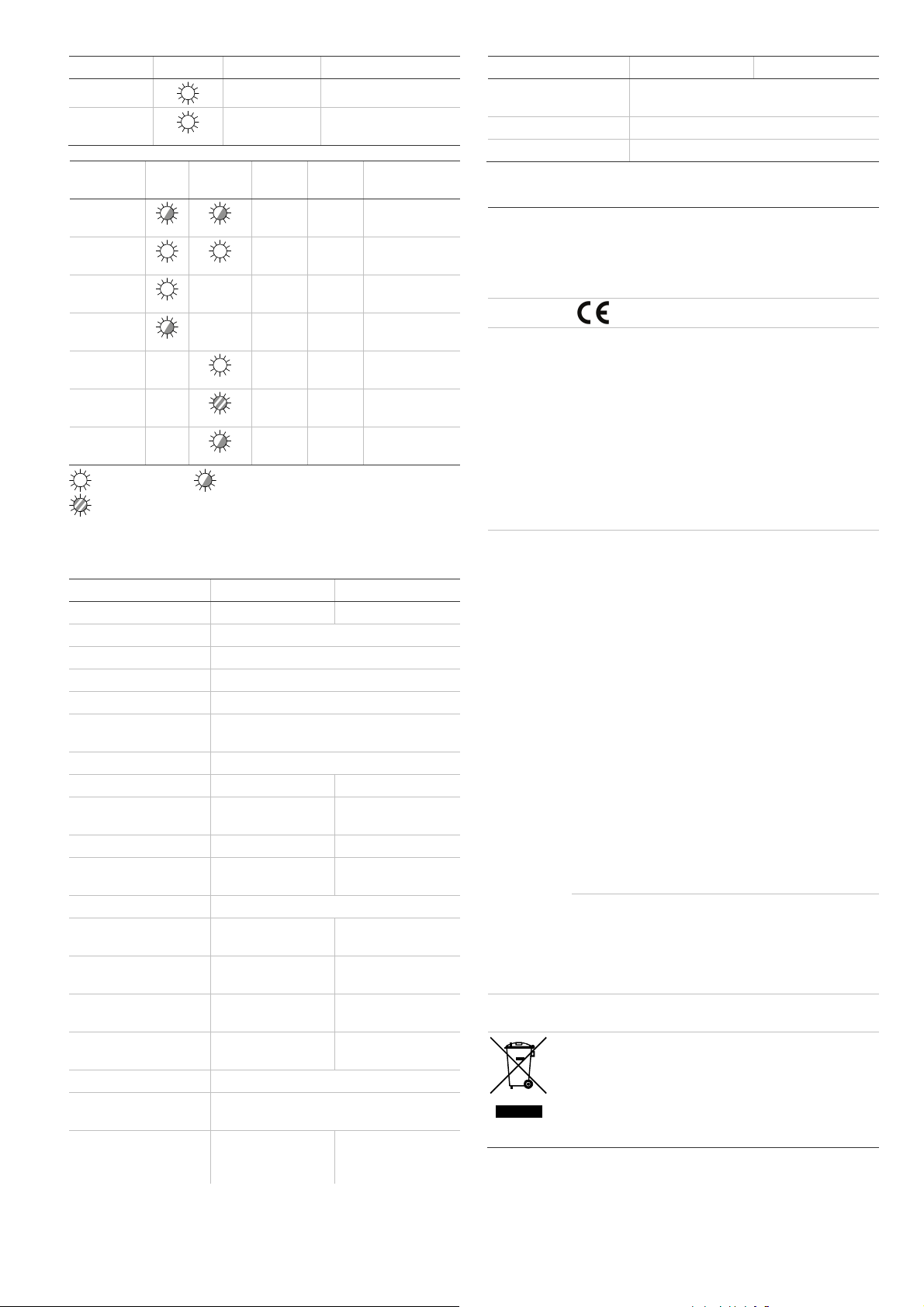
PIR Red LED Alarm relay To reset
Low voltage
PIR intruder
alarm
PIR/AM Red
LED
Start up
Low voltage
PIR intruder
alarm
Latched PIR
(Memory)
AM alarm
After AM
reset
Technical
fault
Continuously on Normal blinking (1 Hz)
Fast blinking (4 Hz)
* Depends on the setting of the DIP switch SW4.
Open (Alarm) Apply correct voltage
Open (Alarm) Automatically after 3 s
Yellow
LED
Alarm
relay
Closed Closed Automatically
Open
(Alarm)
Open
(Alarm)
Switch to Night
Open*
(Alarm)
Switch to Night
Open
AM
relay
Open
(Alarm)
Automatically
Open
(Alarm)
(Alarm)
To reset
after 60 s
Apply correct
voltage
after 3 s
mode
See DIP
switch 3
mode
Do a successful
walk test
Specifications
VE1120 VE1120AM
Detector PIR PIR with AM
Signal processing V2E
Range 20 m
Optical 11 high-density mirror curtains
Memory Yes
Input power
For UL/cUL installations
Peak-to-peak ripple 2 V (at 12 VDC)
Detector start-up time 25 s 60 s
Normal current
For UL/cUL installations
Current in alarm 1.2 mA 3.8 mA
Maximum current
(LED on)
Mounting height 1.8 to 3.0 m (5.9 ft.to 9.8 ft.)
Target speed range 30 cm/s to 3 m/s
Alarm (NC) / Tamper
relay characteristic
Pry-off tamper (not
evaluated by UL/cUL)
AM relay characteristic — 80 mA
PIR Alarm time 3 s
Operating temperature
For UL/cUL installations
Dimensions (H x W x D) 125 × 55 × 60 mm
9 to 15 VDC (12 V nominal)
10 to 15 VDC (12 V nominal)
6.5 mA
0.078 W
11 mA 24 mA
(1 ft./s to 10 ft./s)
80 mA, 30 VDC,
resistive
Optional Onboard (yes)
−10 to +55°C (14 to 130°F)
0 to 49°C ( 32 to 120°F )
(4.92 x 2.16 x
2.36 in.)
10 mA
—
20 cm/s to 3 m/s
(0.65 ft./s to 10 ft./s)
80 mA, 30 VDC
at 30 VDC max.
125 × 65 × 60 mm
(4.92 x 2.6 x 2.36 in.)
VE1120 VE1120AM
Relative humidity 95% max. noncondensing
Weight 150 g
IP/IK rating IP30 IK02
Regulatory information
Manufacturer UTC Fire & Security Americas Corporation, Inc.
1275 Red Fox Rd., Arden Hills, MN 55112-6943, USA
Authorized EU manufacturing representative:
UTC Fire & Security B.V.
Kelvinstraat 7, 6003 DH Weert, Netherlands
Certification
UL/cUL The product must be connected to a listed burglar
FCC Note: This equipment has been tested and found to
This device complies with part 15 of the FCC Rules.
IC This Class B digital apparatus complies with Canadian
system compatible control unit or power supply unit,
which provides a minimum 4 hours of standby power
and has a voltage output between 10 and 15 VDC.
All wiring must be made according to National
Electrical Code, NFPA70, and CSA C22.1, Canadian
Electrical Code Part I, Safety Standards for Electrical
Installations.
Perform walk test at least one per year.
Use only a listed power-limited supply.
VE1120AM has not been evaluated by UL/cUL.
comply with the limits for a Class B digital device,
pursuant to part 15 of the FCC Rules. These limits are
designed to provide reasonable protection against
harmful interference in a residential installation. This
equipment generates, uses and can radiate radio
frequency energy and, if not installed and used in
accordance with the instructions, may cause harmful
interference to radio communications. However, there
is no guarantee that interference will not occur in a
particular installation. If this equipment does cause
harmful interference to radio or television reception,
which can be determined by turning the equipment off
and on, the user is encouraged to try to correct the
interference by one or more of the following measures:
• Reorient or relocate the receiving antenna
• Increase the separation between the equipment
• Connect the equipment into an outlet on a circuit
• Consult the dealer or an experienced radio/TV
Operation is subject to the following two conditions:
(1) This device may not cause harmful interference,
and (2) this device must accept any interference
received, including interference that may cause
undesired operation.
ICES-003.
2002/96/EC (WEEE directive): Products marked with
this symbol cannot be disposed of as unsorted
municipal waste in the European Union. For proper
recycling, return this product to your local supplier
upon the purchase of equivalent new equipment, or
dispose of it at designated collection points. For more
information see: www.recyclethis.info.
Contact information
www.utcfireandsecurity.com or www.interlogix.com
(UL/cUL Installations)
and receiver
different from that to which the receiver is
connected
technician for help
P/N 146279999-2 (ML) • REV C • ISS 28JUN12 5 / 32
Page 6

Customer support: www.interlogix.com/customer-support
DA: Installationsvejledning
Introduktion
VE1120-serien omfatter VE1120 PIR og VE1120AM PIR-AMrumdetektorer. De har patenteret spejl, pyro og
signalbehandlingsteknologi.
Installationsvejledning
Den anvendte teknologi i disse detektorer er modstandsdygtig
over for falske alarmer. Undgå imidlertid mulige årsager til
ustabilitet (se Figur 1), f.eks.:
• Direkte sollys på detektoren
• Kraftig træk på detektoren.
• Varmekilder inden for detektorens synsfelt
• Dyr inden for detektorens synsfelt
• Blokering af detektorens synsfelt med store genstande
som f.eks. møbler
• Genstand under 50 cm (20 in.) fra anti-maskeringsdetektor
(AM)
• Installation af to detektorer mod hinanden og mindre end
50 cm (20 in.) fra hinanden (kun AM-detektorer)
Installation af detektoren
Figur 7 symbolforklaring
Punkt Beskrivelse
(1) Standardtilslutning (fabriksstandard)
(2) Dobbelt sløjfe-tilslutning
CP Central
WT Gangtest
MORGEN Antimaskning
D/N Dag/nat
Rtest Fjernbetj test
Sådan installeres detektoren:
1. Tag dækpladen af og fjern skruen (se Figur 2, trin 1).
2. Åbn forsigtigt detektoren med en skruetrækker (Figur 2,
trin 2 og 3).
3. Gør soklen fast til væggen mellem 1,8 og 3,0 m (5,9 og
9,8 ft.) fra gulvet. Til fladmontering anvendes mindst to
skruer (DIN 7998) i position A. Til hjørnemontering
anvendes skruer i position B eller C (Figur 3). Til at
installere vægsabotagekontakt anvendes position A
eller C.
4. Tilslut detektoren (se figur 3 og 7).
5. Vælg de ønskede jumper- og DIP-switch-indstillinger (se
figur 5). Se "Jumper settings" på side 4, hvis du ønsker
erligere oplysninger.
yd
6. Fjern afskærmningen og påsæt klæbemærker efter behov
(se eksempel i Figur 6).
7. Til loftsmontering med 90 graders anvendelse benyttes
SB01-svingmonteringskonsol.
8. Luk frontlågen.
9. Isæt skruen og anbring dækpladen.
Til EN 50131 Grade 3-installationer må monteringsposition B
ikke anvendes.
Jumper-indstillinger
Se jumpernes placeringer i detektoren i figur 5.
J1: Bruges ikke
J3 og J4: Dobbelt løkkeindstilling
Bruges til indstilling af alarm- og sabotagerelæ. Den giver dig
mulighed for at tilslutte detektoren til et kontrolpanel. Brug
jumpers 3 og 4. Se Figur 7.
Brug fjerntest (RT) til at afprøve detektoren fra kontrolpanelet.
Detektoren aktiverer alarmrelæet, hvis testresultatet er positivt
og AM-relæet, hvis testresultatet er negativt.
J6: Polaritetsindstilling af kontrolspænding (CV)
Til (fabriksstandard):
• Detektoren er i dagtilstand (system frakoblet), når D/Ninput tilsluttes GND (terminal 1)
• Detektoren er i nattilstand (system tilkoblet), når D/N-input
tilsluttes +12 V (terminal 2)
• Detektoren er i tilstanden gangtest fra (LED er
deaktiveret), når WT-input tilsluttes GND (terminal 1)
• Detektoren er i tilstanden gangtest til (LED er aktiveret),
når WT-input tilsluttes +12 V (terminal 2)
Fra:
• Detektoren er i dagtilstand (system frakoblet), når D/Ninput tilsluttes +12 V (skrueterminal 2)
• Detektoren er i nattilstand (system tilkoblet), når D/N-input
tilsluttes GND (terminal 1)
• Detektoren er i tilstanden gangtest fra (LED er
deaktiveret), når WT-input tilsluttes +12 V (terminal 2)
• Detektoren er i tilstanden gangtest til (LED er aktiveret),
når WT-input tilsluttes GND (terminal 1)
D/N- og WT-funktionalitet
D/N-input:
• Styrer LED-funktionen sammen med WT-input.
• Nulstiller alarmhukommelsen
• Styrer AM-relæfunktionen i tilstand NAT sammen med
SW1.
WT-input styrer LED-funktionen sammen med D/N-input.
Når detektoren er i dagtilstand og gangtest er til, kan
detektorens LED aktiveres. Se "LED indication" på side 4, hvis
nsker yderligere oplysninger.
du ø
I nattilstand er LED altid slået fra.
Hvis der registreres en PIR-indbrudsalarm og detektoren
skifter tilbage til dagtilstand, begynder den røde LED at blinke
for at angive en alarm i hukommelsen.
Alarmhukommelsen nulstilles ved at skifte detektoren til nattilstand.
Dipswitch-indstillinger
Fabriksstandard:
54321
ON
SW 1: Når signal AM (antimaskning) eller TF (teknisk fejl)
udsendes
Til: Viser kun AM eller TF, når systemet er i dagtilstand
(fabriksstandard).
Fra: Viser altid AM eller TF i nat- eller dagtilstand.
6 / 32 P/N 146279999-2 (ML) • REV C • ISS 28JUN12
Page 7

SW 2: AM-følsomhed
Til: Vælger højere AM-følsomhed. AM-relæet reagerer i løbet
af 6 sekunder.
Fra: Vælger standard AM-følsomhed. AM-relæet reagerer i
løbet af 12 sekunder (fabriksstandard).
SW 3: Nulstiller AM/TF-output
Systemet nulstiller kun en AM-alarm, hvis det har sikret, at
årsagen til AM-alarmen er fjernet. Hvis AM-strømkredsen ikke
kan vende tilbage til de originale referenceniveauer, så er
detektoren enten maskeret eller måske beskadiget. Ejeren skal
foretage visuel kontrol af, om detektoren stadig er fuld
funktionsdygtig.
Til: Nulstiller AM- eller TF-status 40 sekunder efter PIR-alarm.
Fra: Nulstiller AM- eller TF-status efter en PIR-alarm, når
systemet er i dag- og gangtesttilstand. Det gule LED blinker
hurtigt. Når systemet er i natstatus, slukkes det gule LED og
systemet nulstilles (fabriksstandard).
SW 4: AM- eller TF-signal udsendes
Til: Viser AM på både AM- og alarmrelæet. Viser TF kun på
AM-relæet (EN 50131).
Fra: Viser AM og TF på AM-relæet (fabriksstandard).
SW 5: Indstilling af LED
Til: Aktiverer altid begge LED-indikatorer på detektoren
(fabriksstandard).
Fra: Indstiller begge LED-indikatorer til at være styret af
gangtest og dag/nat. Det aktiverer hukommelsesfunktionen i
detektoren.
LED-angivelse
PIR Rød LED Alarmrelæ Til nulstilling
Start
Lav spænding
PIR-indbrudsalarm
PIR/AM Rød
LED
Start
Lav spænding
PIRindbrudsalarm
Fastholdt PIR
(hukommelse)
AM-alarm
Efter AMnulstilling
Teknisk fejl
Lukket Automatisk efter
Åben (alarm) Anvend korrekt
Åben (alarm) Automatisk efter
Gul
Alarm-
LED
relæ
Lukket Lukket Automatisk efter
Åben
(alarm)
Åben
(alarm)
Skift til
Åben*
(alarm)
Skift til
Åben
25 sek.
spænding
3 sek.
AMrelæ
Åben
(alarm)
Automatisk efter
Åben
(alarm)
(alarm)
Til nulstilling
60 sek.
Anvend korrekt
spænding
3 sek.
nattetilstand
Se DIP-switch 3
nattetilstand
Udfør gangtest
uden fejl
Specifikationer
VE1120 VE1120AM
Detektor PIR PIR med AM
Signalbehandling V2E
Rækkevidde 20 m
Optisk 11 spejlgardiner med høj densitet
Hukommelse Ja
Input-strøm 9 til 15 V DC (12 V nominelt)
Peak-to-peak ripple 2 V (ved 12 VDC)
Detektoropstartstid 25 sek. 60 sek.
Normal strøm 6,5 mA 10 mA
Strøm ved alarm 1,2 mA 3,8 mA
Maks. strøm (LED til) 11 mA 24 mA
Monteringshøjde 1,8 til 3,0 m
Indstilling af
detekteringshastighed
Alarm (NC) /
sabotagerelæegenskab
Vægsabotagekontakten Valgfri Tilsluttet (ja)
AM-relæegenskaber — 80 mA ved maks.
PIR-alarmtid 3 sek.
Driftstemperatur −10 to +55°C
Mål (H x B x D) 125 × 55 × 60 mm 125 × 65 × 60 mm
Relativ luftfugtighed maks. 95% ikke-kondenserende
Vægt 150 g
IP-/IK-klasse IP30 IK02
Lovgivningsmæssig information
Producent UTC Fire & Security Americas Corporation, Inc.
Certificering
Kontaktinformation
www.utcfireandsecurity.com, www.interlogix.com
Kundesupport: www.interlogix.com/customer-support
30 cm/s til 3 m/s 20 cm/s til 3 m/s
80 mA, 30 VDC,
resistiv
1275 Red Fox Rd., Arden Hills, MN 55112-6943, USA
Virksomhedens autoriserede repræsentant i EU:
UTC Fire & Security B.V.
Kelvinstraat 7, 6003 DH Weert, Netherlands
2002/96/EC (WEEE-direktiv): Produkter mærket med
dette symbol må ikke bortskaffes som usorteret
kommunalt affald i den Europæiske Union. For at opnå
korrekt genbrug af dette produkt, skal det afleveres til
din lokale leverandør, når du køber tilsvarende nyt
udstyr. Det kan også bortskaffes på en
genbrugsstation. Se mere information her:
www.recyclethis.info.
80 mA, 30 VDC
30 V
Løbende til Normal blink (1 Hz)
Hurtig blink (4 Hz)
* Afhænger af indstilling af DIP-switch SW4.
P/N 146279999-2 (ML) • REV C • ISS 28JUN12 7 / 32
Page 8

DE: Installationsdatenblatt
Verwenden Sie für Installationen gemäß EN 50131
Sicherheitsstufe 3 nicht Montageposition B.
Einführung
Die VE1120-Serie umfasst die Bewegungsmelder VE1120 PIR
und VE1120AM PIR-AM. Die Melder verfügen über einen
patentierten Spiegel sowie Pyro- und
Signalverarbeitungstechnologie.
Installationsanleitung
Die Technologie in diesen Meldern dient zur Vermeidung
falscher Alarmmeldungen. Dennoch sollten Sie potenzielle
Instabilitätsfaktoren vermeiden (siehe Abb. 1), darunter:
• Direkte Sonneneinstrahlung auf den Melder
• Starke Zugluft am Melder
• Hitzequellen innerhalb des Erfassungsbereichs des
Melders
• Tiere innerhalb des Erfassungsbereichs des Melders
• Verdecken des Erfassungsbereichs des Melders durch
große Objekte, wie z. B. Möbel
• Objekte innerhalb von 50 cm des Melders mit
Abdecküberwachung (AM)
• Montage zweier gegenüberliegender Melder in einem
Abstand von weniger als 50 cm (nur AM-Melder)
Installation des Melders
Legende Abbildung 7
Element Bedeutung
(1) Standardverbindung (Werkseinstellung)
(2) Dual-MG-Anschaltung
CP Control Panel (Einbruchmeldezentrale)
WT Walk test (Gehtest)
AM Antimasking (Abdecküberwachung)
D/N Day/night (Tag/Nacht)
Rtest Remote test (Ferntest)
Montage des Bewegungsmelders:
1. Nehmen Sie den kundenspezifischen Einsatz ab und
entfernen Sie die Schraube (siehe Abb. 2, Schritt 1).
2. Öffnen Sie den Melder vorsichtig mit einem
Schraubendreher (siehe Abb. 2, Schritt 2 und 3).
3. Befestigen Sie den Sockel in einem Abstand von 1,80 m
bis 3 m vom Boden an der Wand. Verwenden Sie für eine
flache Montage mindestens zwei Schrauben (DIN 7998) in
den Positionen A. Verwenden Sie für eine Eckmontage
Schrauben in den Positionen B oder C (Abb. 3).
Verwenden Sie zum Einbau eines Abreißkontakts
Position A oder C.
4. Verdrahten Sie den Melder (siehe Abb. 3 und 7).
5. Wählen Sie die gewünschten Steckbrücken- und DIPSchalter-Einstellungen aus (siehe Abb. 5). Weitere
Informationen finden Sie in Abschnitt “Steckbrücken-
lungen” unten.
Einstel
6. Entfernen Sie die Abdeckungen und bringen Sie bei
Bedarf die Aufkleber an (Abb. 6 zeigt ein Beispiel).
7. Verwenden Sie für Deckenmontagen, bei der eine
Überwachung von 90° erforderlich ist, den
Befestigungssatz für Wand- und Deckenmontagen (SB01).
8. Schließen Sie die Abdeckung.
9. Setzen Sie die Schraube und den kundenspezifischen
Einsatz ein.
Steckbrücken-Einstellungen
Siehe Abb. 5 für die Anordnung der Steckbrücken im Melder.
J1: Nicht verwendet
J3 und J4: Einstellung für Dual-Meldegruppe
Dient zur Einstellung des Alarm- und Sabotagerelais. Sie
können damit den Melder an eine beliebige
Einbruchmeldezentrale anschließen. Verwenden Sie die
Steckbrücken 3 und 4. Siehe Abb. 7.
Verwenden Sie Ferntest (RT), um den Melder von der
Einbruchmeldezentrale aus zu testen. Der Melder aktiviert das
Alarmrelais, wenn das Testergebnis positiv ist. Bei einem
negativen Testergebnis wird das Abdeckungs(AM)-Relais
aktiviert.
J6: Polaritätseinstellung der Steuerspannung (CV)
Ein (Werkseinstellung):
• Der Melder befindet sich im Tagbetrieb (System unscharf),
wenn der D/N-Eingang mit GND (Anschlussklemme 1)
verbunden ist.
• Der Melder befindet sich im Nachtbetrieb (System scharf),
wenn der D/N-Eingang mit +12 V (Anschlussklemme 2)
verbunden ist.
• Der Melder befindet sich im Betrieb „Gehtest aus“ (LEDs
sind deaktiviert), wenn der WT-Eingang mit GND
(Anschlussklemme 1) verbunden ist.
• Der Melder befindet sich im Betrieb „Gehtest an“ (LEDs
sind aktiviert), wenn der WT-Eingang mit +12 V
(Anschlussklemme 2) verbunden ist.
Aus:
• Der Melder befindet sich im Tagbetrieb (System unscharf),
wenn der D/N-Eingang mit +12 V (Anschlussklemme 2)
verbunden ist.
• Der Melder befindet sich im Nachtbetrieb (System scharf),
wenn der D/N-Eingang mit GND (Anschlussklemme 1)
verbunden ist.
• Der Melder befindet sich im Betrieb „Gehtest aus“ (LEDs
sind deaktiviert), wenn der WT-Eingang mit +12 V
(Anschlussklemme 2) verbunden ist.
• Der Melder befindet sich im Betrieb „Gehtest an“ (LEDs
sind aktiviert), wenn der WT-Eingang mit GND
(Anschlussklemme 1) verbunden ist.
D/N- und WT-Funktion
Der D/N-Eingang:
• steuert zusammen mit dem WT-Eingang den LED-Betrieb.
• setzt den Alarmspeicher zurück.
• steuert zusammen mit SW1 die AM-Relaisfunktion
während des Nachtbetriebs.
Der WT-Eingang steuert zusammen mit dem D/N-Eingang den
LED-Betrieb.
Wenn sich der Melder im Tagbetrieb und Betrieb „Gehtest an“
befindet, können die LEDs des Melders aktiviert werden.
Weitere Informationen finden Sie in Abschnitt “
unten.
ährend des Nachtbetriebs sind die LEDs stets ausgeschaltet.
W
Wenn während des Nachtbetriebs ein PIR-Einbruchalarm
erkannt wird und der Melder wieder in den Tagbetrieb
umschaltet, beginnt die rote LED zu blinken, um auf den Alarm
im Speicher hinzuweisen.
LED-Anzeige”
8 / 32 P/N 146279999-2 (ML) • REV C • ISS 28JUN12
Page 9

Der Alarmspeicher wird durch Schalten des Melders in den
PIR/AM Rote
Nachtbetrieb zurückgesetzt.
Start
DIP-Schaltereinstellungen
Werkseitige Einstellung:
54321
ON
SW 1: Wann Abdeckungs(AM)- oder Technischer
Fehler(TF)-Ausgabe signalisiert werden sollten
Ein: Signalisiert AM oder TF nur, wenn sich das System im
Tagbetrieb (unscharf; Werkseinstellung) befindet.
Aus: Signalisiert AM oder TF immer im Tag- und Nachtbetrieb.
SW 2: AM-Empfindlichkeit
Ein: Wählt eine höhere Stufe der Abdeckungsempfindlichkeit
aus. AM-Relais reagiert innerhalb von 6 Sekunden.
Aus: Wählt die Standard-Abdeckungsempfindlichkeit aus. AMRelais reagiert innerhalb von 12 Sekunden (Werkseinstellung).
SW 3: Zurücksetzen des AM/TF-Ausgangs
Das System setzt einen AM-Alarm nur zurück, wenn es sicher
ist, dass die Ursache des AM-Alarms behoben wurde. Wenn
der AM-Schaltkreis nicht zu seiner ursprünglichen
Referenzebene zurückkehren kann, ist entweder der Melder
noch abgedeckt oder wurde möglicherweise beschädigt. Der
Betreiber sollte dann visuell überprüfen, ob der Melder noch
voll funktionsfähig ist.
Ein: Setzt den AM- oder TF-Status 40 Sekunden nach einem
PIR-Alarm zurück.
Aus: Setzt den AM- oder TF-Status nach einem PIR-Alarm
zurück, wenn das System in den Tagbetrieb und GehtestModus geschaltet wurde. Die gelbe LED blinkt dann schnell.
Wenn sich das System im Nachtbetrieb (scharf) befindet,
erlischt die gelbe LED und das System wird zurückgesetzt
(Werkseinstellung).
SW 4: Signalisiert AM- oder TF-Ausgang
Ein: Signalisiert AM (Abdecküberwachung) auf dem AM- und
auf dem Alarmrelais. Signalisiert TF (Technischer Fehler) nur
auf dem AM-Relais (EN 50131).
Aus: Signalisiert AM und TF auf dem AM-Relais
(Werkseinstellung).
SW 5: Einstellen der LEDs
Ein: Aktiviert beide LEDs am Melder dauerhaft
(Werkseinstellung).
Aus: Beide LEDs werden durch den Eingang für Gehtest (WT)
und Tag/Nacht (D/N) gesteuert. Dies aktiviert die
Speicherfunktion des Melders.
LED-Anzeige
PIR Rote LED Alarmrelais Zurücksetzen
Start
Niederspannung
PIREinbruchalarm
Geschlossen Automatisch nach
Offen (Alarm) Verwenden Sie die
Offen (Alarm) Automatisch nach 3 s
25 s
korrekte Spannung.
Niederspannung
PIREinbruchalarm
PIR-Speicher
AM-Alarm
Nach
Zurücksetzen
von AM
Technischer
Fehler
* Hängt von der Einstellung des DIP-Schalters SW4 ab.
Technische Daten
VE1120 VE1120AM
Melder PIR PIR mit AM
Signalverarbeitung V2E
Reichweite 20 m
Optisch 11 Spiegelvorhänge mit hoher Dichte
Speicher Ja
Versorgungsspannung 9 bis 15 V Gleichspannung (12 V nominal)
Spitze/SpitzeBrummspannung
Meldereinschaltzeit 25 s 60 s
Normale Stromaufnahme 6,5 mA 10 mA
Stromaufnahme bei
Alarm
Max. Stromaufnahme
(LED an)
Montagehöhe 1,8 bis 3,0 m
Erfassungs–
geschwindigkeits–bereich
Eigenschaften
Alarmrelais (NC) /
Sabotagerelais
Abreißkontakt Optional Integriert (ja)
Eigenschaften AM-Relais — 80 mA bei 30 V
PIR-Alarmdauer 3 s
Betriebstemperatur –10 bis +55 °C
Abmessungen (H x B x T) 125 × 55 × 60 mm 125 × 65 × 60 mm
Relative Luftfeuchtigkeit 95 % max., nicht kondensierend
Gewicht 150 g
IP/IK-Einstufung IP30 IK02
Gelbe
LED
LED
Ständig an Normales Blinken (1 Hz)
Schnelles Blinken (4 Hz)
Alarmrelais
Gesch. Gesch. Automatisch nach
Offen
(Alarm)
Offen
(Alarm)
Schalten Sie in
Offen*
(Alarm)
Schalten Sie in
Offen
2 V (bei 12 V Gleichspannung)
1,2 mA 3,8 mA
11 mA 24 mA
30 cm/s bis 3 m/s 20 cm/s bis 3 m/s
80 mA, 30 V
Gleichspannung,
resistiv
AMRelais
Offen
(Alarm)
Automatisch nach
Offen
(Alarm)
(Alarm)
Zurücksetzen
60 s
Verwenden Sie
die korrekte
Spannung.
3 s
den Nachtbetrieb
um.
Siehe DIPSchalter 3
den Nachtbetrieb
um.
Führen Sie einen
erfolgreichen
Gehtest durch.
80 mA, 30 VDC
Gleichspannung max.
P/N 146279999-2 (ML) • REV C • ISS 28JUN12 9 / 32
Page 10

Zertifizierung und Einhaltung
Hersteller UTC Fire & Security Americas Corporation, Inc.
1275 Red Fox Rd., Arden Hills, MN 55112-6943, USA
Autorisierter EU-Herstellungsrepräsentant:
UTC Fire & Security B.V.
Kelvinstraat 7, 6003 DH Weert, Niederlande
Zertifizierung
2002/96/EG (WEEE-Richtlinie): Produkte, die mit
diesem Symbol gekennzeichnet sind, dürfen in der
Europäischen Union nicht über unsortierten Hausmüll
entsorgt werden. Um die ordnungsgemäße
Wiederverwertung zu gewährleisten, geben Sie dieses
Produkt beim Kauf eines gleichwertigen neuen Geräts
an Ihren Händler vor Ort zurück, oder geben Sie es an
einer entsprechend gekennzeichneten Sammelstelle
ab. Weitere Informationen hierzu finden Sie auf der
folgenden Website: www.recyclethis.info.
Kontaktinformation
www.utcfireandsecurity.com oder www.interlogix.com
Kontaktinformationen für den Kundendienst finden Sie auf
www.interlogix.com/customer-support
ES: Hoja de instalación
Introducción
La serie VE1120 incluye los sensores de movimiento VE1120
PIR y VE1120AM PIR-AM. Cuentan con tecnología patentada
de espejos, sensores piroeléctricos y procesamiento de la
señal.
Nota: VE1120AM no ha sido evaluada por UL/cUL.
Instrucciones para la instalación
La tecnología utilizada en estos detectores resiste riesgos de
falsas alarmas. Sin embargo, debe evitar posibles causas de
inestabilidad (consulte la figura 1), como por ejemplo:
• Luz solar directa en el detector.
• Fuertes corrientes de aire sobre el detector.
• Fuentes de calor dentro del campo de visión del detector.
• Animales dentro del campo de visión del detector.
• Oscurecer el campo de visión del detector con objetos de
gran tamaño, como por ejemplo mobiliario.
• Objetos a menos de 50 cm del detector antimáscara (AM).
• Instalar dos detectores uno en frente del otro a menos de
50 cm. de distancia (solo detectores AM).
Instalación del detector
Leyenda de la figura 7
Elemento Descripción
(1) Conexión estándar (predeterminada de fábrica)
(2) Conexión de doble bucle
CP Panel de control
WT Prueba de detección
AM Antimáscara
D/N Día/noche
Rtest Prueba remota
Cómo instalar el detector
1. Levante la tapa de la carcasa y saque el tornillo (consulte
la figura 2, paso 1).
2. Usando un destornillador, abra el detector con cuidado
(consulte la figura 2, pasos 2 y 3).
3. Fije la base a la pared a una altura de entre 1,8 y 3 m del
suelo. Para realizar el montaje en una superficie plana
utilice como mínimo dos tornillos (DIN 7998) colocados en
posición A. Para los montajes en esquinas los tornillos
han de colocarse en las posiciones B o C (figura 3). Para
instalar un tamper de pared, utilice la posición A o C.
Nota: el uso del tamper de pared no ha sido evaluado por
UL/cUL.
4. Conecte los cables del detector (consulte las figuras 3
y 7).
Instalación de UL/cUL: todas las conexiones se deben
realizar de acuerdo con el National Electrical Code
(Código nacional de electricidad) o NFPA70
estadounidense y la primera parte, referida a las normas
de seguridad para instalaciones eléctricas, del Canadian
Electrical Code (Código de electricidad canadiense) o
CSA C22.1.
5. Seleccione el puente que desee y la configuración de los
conmutadores DIP (consulte la figura 5). Para obtener
más información, consulte “Configuración de puentes”
más adelante.
Retire las máscaras y pegue las etiquetas si es necesario
6.
(consulte la figura 6 como ejemplo).
7. Para aplicaciones de montaje en el techo que precisen de
una cobertura de 90º utilice el soporte de montaje
giratorio SB01.
Nota: el uso del soporte de montaje giratorio no ha sido
evaluado por UL/cUL. Las aplicaciones de montaje en el
techo no han sido evaluadas por UL/cUL.
8. Cierre la carcasa.
9. Inserte el tornillo y coloque la tapa de la carcasa.
Para las instalaciones EN 50131 de Grado 3, no utilice la
posición de montaje B.
Configuración de puentes
Consulte la figura 5 para saber dónde están situados los
puentes en el detector.
J1: no se utiliza
J3 y J4: configuración de bucle doble
Configura los relés de alarma y tamper. Le permite conectar el
detector a cualquier panel de control. Utilice los puentes 3 y 4.
Consulte la figura 7.
Utilice la prueba remota (RT) para realizar una prueba del
detector desde el panel de control. El detector activará el relé
de alarma si la prueba da resultados positivos, y el relé de AM
si la prueba da resultados negativos.
J6: configuración de polaridad del voltaje de control (VC)
Activado (opción predeterminada):
• El detector se encuentra en modo Día (sistema
desarmado) cuando la entrada D/N se encuentra
conectada a GND (terminal 1).
• El detector se encuentra en modo Noche (sistema
armado) cuando la entrada D/N se encuentra conectada a
+12 V (terminal 2).
• El detector se encuentra en modo Prueba de detección
desactivada (con los LED deshabilitados) cuando la
entrada WT se encuentra conectada a GND (terminal 1).
10 / 32 P/N 146279999-2 (ML) • REV C • ISS 28JUN12
Page 11

• El detector se encuentra en modo Prueba de detección
activada (con los LED habilitados) cuando la entrada WT
se encuentra conectada a +12 V (terminal 2).
Desactivado:
• El detector se encuentra en modo Día (sistema
desarmado) cuando la entrada D/N se encuentra
conectada a +12 V (terminal de tornillo 2).
• El detector se encuentra en modo Noche (sistema
armado) cuando la entrada D/N se encuentra conectada a
GND (terminal 1).
• El detector se encuentra en modo Prueba de detección
desactivada (con los LED deshabilitados) cuando la
entrada WT se encuentra conectada a +12 V (terminal 2).
• El detector se encuentra en modo Prueba de detección
activada (con los LED habilitados) cuando la entrada WT
se encuentra conectada a GND (terminal 1).
Funciones D/N y WT
Entrada D/N:
• Controla las funciones LED junto con la entrada WT.
• Restablece la memoria de alarma.
• Controla la función de relé AM durante el modo NOCHE
junto con SW1.
La entrada WT controla la función LED junto con la entrada
D/N.
Cuando el detector se encuentra en los modos Día y Prueba
de detección activada, los LED se pueden activar. Para
obtener más información, consulte “Indicación LED” más
lante.
ade
Durante el modo Noche, los LED se encuentran desactivados
en todo momento.
Si se detecta una alarma PIR de intruso en el modo Noche y el
detector vuelve al modo Día, el LED rojo comienza a
parpadear para indicar que existe una alarma en la memoria.
La memoria de alarma se restablece cambiando el detector al
modo Noche.
Configuración del interruptor DIP
Predeterminado de fábrica:
54321
ON
INTERRUPTOR 1: para señalar la salida AM (antimáscara)
o FT (fallo técnico)
Activado: señala AM o FT solo cuando el sistema está en
modo Día (predeterminado de fábrica).
Desactivado: siempre señala AM o FT en el modo Día y
Noche.
INTERRUPTOR 2: sensibilidad de AM
Activado: selecciona un nivel más alto de sensibilidad de AM.
El relé de AM reacciona a los 6 segundos.
Desactivado: selecciona la sensibilidad estándar de AM. El
relé de AM reacciona a los 12 segundos (predeterminado de
fábrica).
INTERRUPTOR 3: restablecimiento de la salida AM/FT
El sistema sólo restablecerá una alarma de AM si tiene total
seguridad de que la causa de la alarma de AM se ha
eliminado. Si el circuito de AM no puede volver a sus niveles
de referencia originales, entonces es que el detector aún está
enmascarado o que ha sufrido algún posible daño. En este
caso, el propietario debe examinar el detector y comprobar
que aún está totalmente operativo.
Activado: restablece los estados de AM o FT 40 segundos
después de una alarma PIR.
Desactivado: restablece el estado de AM o FT después de una
alarma PIR si el sistema está en los modos de Prueba de
detección y Día. El indicador LED amarillo parpadeará
rápidamente. Si el sistema está en estado Noche, el indicador
LED amarillo se apagará y el sistema se restablecerá
(predeterminado de fábrica).
INTERRUPTOR 4: señalización de salida AM o FT
Activado: señala AM en el relé de AM y el relé de alarma.
Señala FT en el relé de AM solamente (EN 50131).
Desactivado: señala AM y FT en el relé de AM
(predeterminado de fábrica).
INTERRUPTOR 5: configuración de indicadores LED
Activado: activa ambos LED en el detector en todo momento
(predeterminado de fábrica).
Desactivado: pone a ambos indicadores LED bajo el control de
las entradas Prueba de paseo y Día/Noche. Esto activa la
función de memoria del detector.
Indicación LED
PIR LED rojo Relé de alarma Restablecimiento
Inicio
Tensión baja
Alarma PIR de
intruso
PIR/AM
LED rojo
Inicio
Tensión
baja
Alarma PIR
de intruso
PIR cerrado
(memoria)
Alarma AM
Después de
restablecer
AM
Fallo técnico
Siempre encendido Parpadeo normal (1 Hz)
Parpadeo rápido (4 Hz)
*Depende de la configuración del interruptor DIP SW4.
Cerrado Automáticamente
Abierto (alarma) Aplicar el voltaje
Abierto (alarma) Automáticamente
Relé de
alarma
LED
amarillo
Cerrado Cerrado Automáticamente
Abierto
(alarma)
Abierto
(alarma)
Cambio a modo
Abierto*
(alarma)
Cambio a modo
Abierto
Relé de
AM
Abierto
(alarma)
Automáticamente
Abierto
(alarma)
(alarma)
después de 25 s
adecuado
después de 3 s
Restablecimiento
después de 60 s
Aplicar el voltaje
adecuado
después de 3 s
Noche
Ver interruptor DIP
3
Noche
Realizar una
prueba de paseo
con éxito
P/N 146279999-2 (ML) • REV C • ISS 28JUN12 11 / 32
Page 12

Especificaciones
VE1120 VE1120AM
Estado del PIR PIR con AM
Procesamiento de la señal V2E
Rango 20 m
Óptico 11 cortinas de espejo de alta
densidad
Memoria Sí
Potencia de entrada
Para instalaciones UL/cUL
Tensión de pico a pico 2 V (a 12 VCC)
Tiempo de arranque del detector 25 s 60 s
Corriente normal
Para instalaciones UL/cUL
Corriente en alarma 1,2 mA 3,8 mA
Corriente máxima
(LED encendido)
Altura de instalación 1,8 a 3,0 m
Rango de velocidades de
destino
Característica del relé de alarma
(NC) / tamper
Tamper de pared (no evaluado
por UL/cUL)
Característica del relé de AM — 80 mA a 30 VCC
Tiempo de alarma PIR 3 s
Temperatura de funcionamiento
Para instalaciones UL/cUL
Dimensiones (Al x An x Pro) 125 × 55 ×
Humedad relativa 95% máx. sin condensación
Peso 150 g
Rango de IP/IK IP30 IK02
9 a 15 VCC (12 V nominal)
10 a 15 VCC (12 V nominal)
6,5 mA
0,078 W
11 mA 24 mA
30 cm/s a 3 m/s 20 cm/s a 3 m/s
80 mA, 30 VCC,
resistente
Opcional En la placa (sí)
−10 a +55°C
0 a 49°C
60 mm
(instalaciones UL/cUL)
10 mA
—
80 mA, 30 VCC
máx.
125 × 65 ×
60 mm
Información normativa
Fabricante UTC Fire & Security Americas Corporation, Inc.
Certificación
1275 Red Fox Rd., Arden Hills, MN 55112-6943, EE.
UU.
Representante de fabricación autorizado en la UE:
UTC Fire & Security B.V.
Kelvinstraat 7, 6003 DH Weert, Países Bajos
UL/cUL El producto se debe conectar a una unidad de control
Información
FCC
Este dispositivo cumple con la Parte 15 de las normas
o unidad de suministro de corriente aprobadas y
compatibles con un sistema antirrobo que
proporcionen un mínimo de 4 horas de alimentación
en espera y tengan una tensión de salida entre 10 y
15 VCC.
Todas las conexiones se deben realizar de acuerdo
con el National Electrical Code (Código nacional de
electricidad) o NFPA70 estadounidense y la primera
parte, referida a las normas de seguridad para
instalaciones eléctricas, del Canadian Electrical Code
(Código de electricidad canadiense) o CSA C22,1.
Realice una prueba de detección al menos una vez al
año.
Utilice solo fuentes de alimentación limitada
aprobadas.
VE1120AM no ha sido evaluada por UL/cUL.
Nota: Este equipo ha sido probado y cumple con los
limites para dispositivos digitales de Clase B,
conforme a la parte 15 de la normativa FCC. Estos
limites esta diseñados para garantizar una protección
razonable contra interferencias nocivas en
instalaciones residenciales.
Este equipo genera, utiliza y puede radiar energía de
radiofrecuencia, y si no se instala y utiliza conforme a
las instrucciones, puede causar interferencias en las
comunicaciones de radio. Sin embargo, no hay
garantías de que las interferencias se produzcan en
instalaciones concretas. Si este equipo causara
interferencias en la recepción de señales de radio ó
televisión, lo cual puede ser determinado apagando y
encendiendo el equipo, se recomienda al usuario que
intente corregir la interferencia mediante una ó mas de
las siguientes acciones:
• Reorientar ó recolocar la antena receptora
• Aumentar la separación entre el equipo y el
receptor
• Conectar el equipo a un circuito de salida
diferente al del receptor
• Consultar al vendedor o a un experto en
radiotelevisión para ayuda
de la FCC. El funcionamiento está sujeto a las dos
condiciones siguientes: (1) que el dispositivo no
provoque interferencias dañinas, y (2) que el
dispositivo acepte las interferencias recibidas,
incluidas las que pudieran provocar un funcionamiento
no deseado.
2002/96/EC (directiva WEEE): los productos
marcados con este símbolo no se pueden desechar
como residuos urbanos no clasificados en la Unión
Europea. Para que se pueda realizar un reciclaje
adecuado, devuelva este producto a su representante
de ventas local al comprar un equipo nuevo similar o
deséchelo en los puntos de recogida designados.
Para obtener más información, consulte:
www.recyclethis.info.
Información de contacto
www.utcfireandsecurity.com o www.interlogix.com
Servicio técnico: www.interlogix.com/customer-support
12 / 32 P/N 146279999-2 (ML) • REV C • ISS 28JUN12
Page 13

FI: Asennusohje
Johdanto
VE1120-sarjaan kuuluvat VE1120 PIR- ja VE1120AM PIR-AM
-liiketunnistimet. Niissä on patentoitu peili-, pyro- ja
signaalinkäsittelyteknologia.
Asennusohjeet
Näissä ilmaisimissa käytetty tekniikka vähentää
virhehälytyksiä. Mahdollisia ilmaisimen toimintaa häiritseviä
tekijöitä, kuten seuraavia, on kuitenkin vältettävä (katso
kuva 1):
• ilmaisimeen suoraan paistava auringonvalo
• ilmaisimeen kohdistuvat voimakkaat ilmavirtaukset
• lämmönlähteet ilmaisimen valvontakentässä
• eläimet ilmaisimen valvontakentässä
• suuret kohteet, kuten huonekalut, jotka peittävät
ilmaisimen valvontakentän
• kohteet, jotka ovat 50 cm päässä antimask-ilmaisimesta
(AM)
• kahden ilmaisimen asentaminen toisiaan kohti ja alle
50 cm päähän toisistaan (vain AM-ilmaisimet)
Ilmaisimen asentaminen
Kuvan 7 selite
Kohta Kuvaus
(1) Standardikytkentä (tehdasasetus)
(2) Kaksoispäätevastussilmukka
CP Keskuslaite
WT Kävelytesti
AM Antimasking (peittämishälytys)
D/N Päivä/yö
Rtest Etätesti
Ilmaisimen asentaminen:
1. Nosta peitelevy ja avaa ruuvi (kts. kuva 2, vaihe 1).
2. Väännä ilmaisin varovasti auki ruuvimeisselin avulla (kts.
kuva 2, vaiheet 2 ja 3).
3. Kiinnitä ilmaisimen pohja seinälle 1,8–3,0 metrin
korkeudelle lattiasta. Jotta ilmaisin tulee mahdollisimman
vakaasti seinää vasten, kiinnitä se vähintään kahdella
ruuvilla (DIN 7998) kohdista A. Jos haluat kiinnittää
ilmaisimen kulmaan, kiinnitä se ruuveilla kohdista B tai C
(kuva 3). Jos haluat suojata ilmaisimen seinästä
irtirepimiseltä, kiinnitä se kohdista A tai C.
4. Kytke ilmaisimen johdot (katso kuvat 3 ja 7).
5. Valitse sopivat oikosulkupalan ja DIP-kytkimen asetukset
(katso kuva 5). Lisätietoja on kohdassa “Oikosulkupalan
asetukset” alla.
Poista peilin peittopalat ja lisää tarrat tarvittaessa (kts.
6.
esimerkki kuvasta 6).
7. Kattoasennuksessa, jossa tarvitaan 90 asteen
kattavuusalue, tulee käyttää SB01-asennusjalkaa.
8. Sulje kansi.
9. Kiinnitä kannen ruuvi paikoilleen ja aseta peitelevy
paikalleen.
Älä käytä asennuskohtaa B EN 50131 luokan 3 asennuksissa.
Oikosulkupalan asetukset
Kuvassa 5 esitetään ilmaisimen oikosulkupalojen (jumperien)
sijainnit.
J1: Ei käytössä
J3 ja J4: Kaksoispäätevastussilmukka-asetus
Tämä määrittää hälytys- ja kansihälytysreleet. Tämän avulla
ilmaisin voidaan yhdistää mihin tahansa keskuslaitteeseen.
Käytä oikosulkupaloja 3 ja 4. Kts. kuva 7.
Käytä Etätesti (RT) -toimintoa ilmaisimen testaamiseen
keskuslaitteelta. Ilmaisin aktivoi hälytysreleen, jos testitulos on
positiivinen, ja AM-releen, jos testitulos on negatiivinen.
J6: Ohjausjännitteen (CV) polariteetti
On (päällä) (tehdasasetus):
• Ilmaisin on päivätilassa, kun D/N-tulo on yhdistetty GNDliitäntään (pääte 1)
• Ilmaisin on yötilassa, kun D/N-tulo on aktivoitu +12 Vlla
(pääte 2)
• Ilmaisin on Kävelytesti pois päältä -tilassa (ledit pois
käytöstä), kun WT-tulo on yhdistetty GND-liitäntään
(pääte 1)
• Ilmaisin on Kävelytesti päällä -tilassa (ledit käytössä), kun
WT-tulo on aktivoitu +12 Vlla (pääte 2)
Off (pois päältä):
• Ilmaisin on päivätilassa, kun D/N-tulo on aktivoitu +12 Vlla
(ruuviliitäntä 2)
• Ilmaisin on yötilassa, kun D/N-tulo on yhdistetty GNDliitäntään (pääte 1)
• Ilmaisin on Kävelytesti pois päältä -tilassa (ledit pois
käytöstä), kun WT-tulo on aktivoitu +12 Vlla (pääte 2)
• Ilmaisin on Kävelytesti päällä -tilassa (ledit käytössä), kun
WT-tulo on yhdistetty GND-liitäntään (pääte 1)
D/N- ja WT-toiminnallisuus
D/N-tulo:
• ohjaa ledien toimintaa yhdessä WT-tulon kanssa.
• nollaa hälytysmuistin
• ohjaa AM-releen toiminnallisuutta yötilan aikana yhdessä
SW1:n kanssa.
WT-tulo ohjaa ledien toimintaa yhdessä D/N-tulojen kanssa.
Kun ilmaisin on päivätilassa ja Kävelytesti päällä -tilassa,
ilmaisimen ledit voidaan aktivoida. Lisätietoja on kohdassa
Ledien merkitys” sivulla 14.
“
Yötilass
Jos ilmaisin on aktivoitunut liikkeestä yötilassa jailmaisin palaa
päivätilaan, punainen ledi vilkkuu muistissa olevan hälytyksen
merkiksi.
Hälytysmuisti nollataan vaihtamalla ilmaisin yötilaan.
a ledit on aina kytketty pois päältä.
DIP-kytkimen asetukset
Tehdasasetus:
54321
ON
SW 1: Milloin AM- (antimask) tai TF (tekninen vika) -tila
aktivoidaan
On (päällä): Aktivoi AM- tai TF-tilan vain kun järjestelmä on
päivätilassa (tehdasasetus).
P/N 146279999-2 (ML) • REV C • ISS 28JUN12 13 / 32
Page 14

Off (pois päältä): Aktivoi aina AM- tai TF-tilan päivä- ja
yötilassa.
SW 2: AM-herkkyys
On (päällä): Korkeampi AM-herkkyystaso. AM-rele reagoi
6 sekunnin peittämisestä.
Off (pois päältä): Standardi AM-herkkyystaso. AM-rele reagoi
12 sekunnin peittämisestä (tehdasasetus).
SW 3: AM/TF-lähdön kuittaaminen
Ilmaisin kuittaa AM-hälytyksen vain jos se on varmistanut, että
AM-hälytyksen aiheuttaja on poistettu. Jos AM-piiri ei voi
palata normaaleihin viitetasoihinsa, tunnistin on joko edelleen
peitettynä tai se on saattanut vaurioitua. Tällöin tulisi tarkistaa
silmämääräisesti, että ilmaisin on edelleen täydessä
toimintakunnossa.
On (päällä): Kuittaa AM- tai TF-tilan 40 sekuntia IR-hälytyksen
jälkeen.
Off (pois päältä): Kuittaa AM- tai TF-tilan IR-hälytyksen jälkeen,
kun järjestelmä on päivä- ja kävelytestitilassa. Keltainen ledi
vilkkuu nopeasti. Kun järjestelmä on yötilassa, keltainen ledi
sammuu ja ilmaisin kuittaantuu (tehdasasetus).
SW 4: AM- tai TF-lähdön aktivointi
On (päällä): AM-hälytys aktivoi sekä AM- että hälytysreleen.
TF-tila aktivoi vain AM-releen (EN 50131).
Off (pois päältä): AM-hälytys ja TF-tila aktivoivat AM-releen
(tehdasasetus)
SW 5: Ledien määrittäminen
On (päällä): Kytkee ilmaisimen molemmat ledit olemaan päällä
aina (tehdasasetus).
Off (pois päältä): Asettaa molemmat ledit toimimaan
Kävelytesti- ja Päivä/yö-tulojen mukaan. Tämä aktivoi
ilmaisimen muistiominaisuuden.
Ledien merkitys
IR
Punainen
ledi
Käynnistys
Matala jännite
Liiketunnistus
IR/AM
Hälytysrele
Kiinni Automaattisesti 25
Avoin (hälytys) Käytä oikeaa jännitettä
Avoin (hälytys) Automaattisesti 3
Nollaus /
kuittaus
sekunnin kuluttua
sekunnin kuluttua
IR/AM
Punainen ledi
Keltainen ledi
Hälytysrele
AM-hälytys
AM-nollauksen
jälkeen
Tekninen vika
Jatkuvasti päällä Vilkkuu normaalisti (1 Hz)
Vilkkuu nopeasti (4 Hz)
* Riippuu DIP-kytkimen SW4 asetuksesta.
Avoin*
(hälytys)
Vaihda yötilaan
Avoin
AM-rele
Avoin
(hälytys)
(hälytys)
Nollaus
Katso DIP-kytkin 3
Tee onnistunut
kävelytesti
Tekniset tiedot
VE1120 VE1120AM
Ilmaisin IR IR + AM
Signaalinkäsittely V2E
Alue 20 m
Optiikka 11 tiheää peiliverhoa
Muisti Kyllä
Tehonsyöttö 9–15 VDC (12 V nimellisteho)
Jännitevaihtelu 2 V (12 VDC:n jännitteellä)
Ilmaisimen käynnistymisaika 25 s 60 s
Normaali virrankulutus 6,5 mA 10 mA
Virta hälytystilassa 1,2 mA 3,8 mA
Enimmäisvirta (ledit päällä) 11 mA 24 mA
Asennuskorkeus 1,8–3,0 m
Kohteen nopeusalue 30 cm/s – 3 m/s 20 cm/s – 3 m/s
Hälytys (NC) /
kansihälytysreleen
ominaisuudet
Irtirepimissuoja Valinnainen Piirikortti (Kyllä)
AM-releen ominaisuudet — 80 mA, maks.
IR-hälytysaika 3 s
Käyttölämpötila −10...+55 °C
Mitat (leveys x korkeus x
syvyys)
Suhteellinen ilmankosteus Enint. 95 %, tiivistymätön
Paino 150 g
IP/IK-luokitus IP30 IK02
80 mA, 30 VDC,
resistiivinen
125 × 55 × 60 mm 125 × 65 ×
80 mA, 30 VDC
30 VDC
60 mm
Sertifiointi ja määräysten noudattaminen
Punainen ledi
Keltainen ledi
Hälytysrele
Käynnistys
Matala jännite
Liiketunnistus
Lukittu IR
(muisti)
14 / 32 P/N 146279999-2 (ML) • REV C • ISS 28JUN12
Kiinni Kiinni Automaattisesti 60
Avoin
(hälytys)
Avoin
(hälytys)
Vaihda yötilaan
AM-rele
Avoin
(hälytys)
Automaattisesti 3
Nollaus
sekunnin kuluttua
Käytä oikeaa
jännitettä
sekunnin kuluttua
Valmistaja UTC Fire & Security Americas Corporation, Inc.
Sertifiointi
1275 Red Fox Rd., Arden Hills, MN 55112-6943, USA
Valtuutettu EU-valmistusedustaja:
UTC Fire & Security BV
Kelvinstraat 7, 6003 DH Weert, Alankomaat
Page 15

2002/96/EC (WEEE direktiivi): Tällä symbolilla
merkittyjä tuotteita ei saa hävittää Euroopan Unionin
alueella talousjätteen mukana kaupungin
jätehuoltoasemille. Oikean kierrätystavan
varmistamiseksi palauta tuote paikalliselle
jälleenmyyjälle tai palauta se elektroniikkajätteen
keräyspisteeseen. Lisätietoja saat osoitteesta:
www.recyclethis.info.
Yhteystiedot
www.utcfireandsecurity.com tai www.interlogix.com
Asiakastuki: www.interlogix.com/customer-support
FR: Fiche d'installation
Introduction
La série VE1120 regroupe les détecteurs de mouvement IRP
VE1120 et IRP-AM VE1120AM. Ceux-ci possèdent une
technologie brevetée de miroir, capteur pyro et traitement du
signal.
Remarque : le VE1120AM n'a pas été évalué par UL/cUL.
Instructions d’installation
La technologie utilisée dans ces détecteurs est conçue pour
résister aux risques de fausses alarmes. Toutefois, il est
conseillé d’éviter les causes d'instabilité potentielles (voir fig. 1)
telles que :
• L’exposition du détecteur à la lumière directe du soleil
• Les courants d’air puissants sur le détecteur
• Les sources de chaleur dans le champ de vision du
détecteur
• La présence d’animaux dans le champ de vision du
détecteur
• L’obstruction du champ de vision du détecteur par des
objets volumineux, comme des meubles
• La présence d’objets à moins de 50 cm du détecteur antimasque (AM)
• L’installation de deux détecteurs face à face à moins de
50 cm de distance (détecteurs AM uniquement)
Installation du détecteur
Légende de la fig. 7
Elément Description
(1) Connexion standard (configuration d'usine par défaut)
(2) Connexion en boucle double
CP Centrale
WT Test de marche
AM Anti-masque
D/N Jour/nuit
Rtest Test à distance
Installation du détecteur :
1. Soulevez le couvercle et retirez la vis (voir fig. 2,
étape 1).
2. A l’aide d’un tournevis, ouvrez délicatement le détecteur
en faisant levier (voir fig. 2, étapes 2 et 3).
3. Fixez la base au mur à une hauteur comprise entre 1,8 m
et 3 m du sol. Pour un montage à plat, utilisez au moins
deux vis (DIN 7998) dans les positions A. Pour un
montage en coin, utilisez des vis en positions B ou C
(Figure 3). Pour installer une autoprotection à
l'arrachement, utilisez la position A ou C.
Remarque : l'utilisation de l'autoprotection à l'arrachement
n'a pas été évaluée par UL/cUL.
4. Raccordez le détecteur (voir figures 3 et 7).
Installations UL/cUL : Tous les câblages doivent être
réalisés selon le National Electrical Code, NFPA70 et CSA
C22,1, Canadian Electrical Code Part I, Safety Standards
for Electrical Installations.
5. Réglez les cavaliers et les commutateurs DIP de manière
appropriée (voir figure 5). Consultez la section “Réglage
du cavalier” ci-dessous pour obtenir plus d’informations.
Retirez les masques et ajoutez les autocollants si
6.
nécessaire (voir fig. 6 pour exemple).
7. Pour les applications de montage au plafond requérant
une couverture de 90 °, utilisez la patte de fixation à
pivot SB01.
Remarque : l'utilisation de la patte de fixation à pivot n'a
pas été évaluée par UL/cUL. Le système de montage au
plafond n'a pas été évalué par UL/cUL.
8. Fermez le panneau de couverture.
9. Insérez la vis et placez l'insert personnalisé.
Pour les installations suivant la norme EN 50131 Niveau 3,
n'utilisez pas la position de montage B.
Réglage du cavalier
Reportez-vous à la figure 5 pour connaître les emplacements
des cavaliers dans le détecteur.
J1 : Non utilisé
J3 et J4 : Configuration de la boucle double
La boucle double permet de régler les relais d’alarme et
d’autoprotection. Elle permet de connecter le détecteur à tout
type de centrale. Elle utilise les cavaliers 3 et 4. Voir la Figure
7.
Utilisez le test à distance (RT) pour tester le détecteur à partir
de la centrale. Le détecteur active le relais d’alarme si le
résultat du test est positif et le relais AM si le résultat du test
est négatif.
J6 : Réglage de la polarité de tension de contrôle (TC)
Position ON (configuration usine par défaut) :
• Le détecteur est en mode Jour (système désarmé) lorsque
l'entrée D/N est connectée à la masse (borne 1)
• Le détecteur est en mode Nuit (système armé) lorsque
l'entrée D/N est connectée au +12 V (borne 2)
• Le détecteur est en mode Test de marche désactivé
(voyants désactivés) lorsque l'entrée WT est connectée à
la masse (borne 1)
• Le détecteur est en mode Test de marche activé (voyants
activés) lorsque l'entrée WT est connectée au +12 V
(borne 2)
Position OFF :
• Le détecteur est en mode Jour (système désarmé) lorsque
l'entrée D/N est connectée au +12 V (borne 2).
• Le détecteur est en mode Nuit (système armé) lorsque
l'entrée D/N est connectée à la masse (borne 1).
• Le détecteur est en mode Test de marche désactivé
(voyants désactivés) lorsque l'entrée WT est connectée à
+12 V (borne 2).
P/N 146279999-2 (ML) • REV C • ISS 28JUN12 15 / 32
Page 16

• Le détecteur est en mode Test de marche activé (voyants
activés) lorsque l'entrée WT est connectée à la masse
(borne 1).
Fonctionnalité D/N et WT
L'entrée D/N :
• Contrôle la fonctionnalité des voyants avec l'entrée WT.
• Réinitialise la mémoire d’alarme
• Contrôle la fonctionnalité du relais AM en mode NUIT
avec SW1.
L'entrée WT contrôle la fonctionnalité des voyants avec
l'entrée D/N.
Lorsque le détecteur est en mode Jour et en mode Test de
marche activé, les voyants du détecteur peuvent être activés.
Consultez la section “Indication du voyant” ci-dessous pour
ir plus d’informations.
obten
En mode Nuit, les voyants sont toujours éteints.
Si une alarme intrusion IRP est détectée en mode Nuit et si le
détecteur revient en mode Jour, le voyant rouge se met à
clignoter pour indiquer qu'une alarme est en mémoire.
La mémoire d'alarme est réinitialisée en basculant le détecteur
en mode Nuit.
Réglages des commutateurs DIP
Configuration usine par défaut :
54321
SW 4 : Signalisation des sorties AM ou PT
Position ON : Signale les sorties AM à la fois sur les relais AM
et d’alarme. Signale les sorties PT sur le relais AM uniquement
(EN 50131).
Position OFF : Signale les sorties AM et PT sur le relais AM
(configuration usine par défaut).
SW 5 : Réglage des témoins lumineux
Position ON : Active en permanence les deux témoins
lumineux du détecteur (configuration usine par défaut).
Position OFF : Met les deux témoins sous contrôle des entrées
test de marche et jour/nuit. Ceci active la fonction de mémoire
du détecteur.
Indication du voyant
IRP Témoin
rouge
Démarrage
Basse tension
Alarme intrusion IRP
IRP/AM
Relais
d’alarme
Fermé Automatiquement
Ouvert (alarme) Utiliser une tension
Ouvert (alarme) Automatiquement
Relais
d’alarme
Relais
AM
Réinitialisation
après 25 s
correcte
après 3 s
Réinitialisation
ON
SW 1 : Quand signaler les sorties AM (anti-masque) ou PT
(problème technique)
Position ON : Signale les alarmes AM ou PT uniquement
quand le système est en mode jour (configuration usine par
défaut).
Position OFF : Signale toujours l’AM ou le PT en mode Jour et
Nuit.
SW 2 : Sensibilité d’anti-masque
Position ON : Augmente la sensibilité d’anti-masque. Le relais
AM réagit en moins de 6 secondes.
Position OFF : Sélectionne la sensibilité d’anti-masque
standard. Le relais AM réagit en moins de 12 secondes
(configuration usine par défaut).
SW 3 : Réinitialisation des sorties AM/PT
Le système réinitialise une alarme AM une fois qu’il est sûr que
la cause de l’alarme AM a été supprimée. Si le circuit AM ne
peut pas revenir à ses niveaux de référence d’origine, soit le
détecteur est toujours masqué, soit il a été endommagé. Le
propriétaire doit alors vérifier physiquement si le détecteur est
toujours fonctionnel.
Position ON : Réinitialise l’état AM ou PT 40 secondes après
une alarme IRP.
Position OFF : Réinitialise l’état AM ou PT suite au
déclenchement d’une alarme IRP, lorsque le système est en
mode jour et test de marche. Le témoin jaune clignote
rapidement. Lorsque le système est en état nuit, le voyant
jaune s’éteint et le système se réinitialise (configuration usine
par défaut).
Témoin rouge
Témoin jaune
Démarrage Fermé Fermé Automatiquement
après 60 s
Basse tension Ouvert
(alarme)
Alarme intrusion
IRP
IRP verrouillé
(mémoire)
Alarme AM
Après
réinitialisation de
l’AM
Problème
technique
Allumé en continu Clignotant (1 Hz)
Clignotement rapide (4 Hz)
* Dépend du réglage du commutateur DIP SW4.
Ouvert
(alarme)
Passer en mode
Ouvert*
(alarme)
Passer en mode
Ouvert
Ouvert
(alarme)
Automatiquement
Ouvert
(alarme)
(alarme)
Utiliser une
tension correcte
après 3 s
nuit
Voir commutateur
DIP 3
nuit
Réussir un test de
marche
Caractéristiques techniques
VE1120 VE1120AM
Détecteur IRP IRP avec AM
Traitement du signal V2E
Portée 20 m
Optique 11 miroirs à rideau haute densité
Mémoire Oui
Puissance d'entrée
Pour les installations UL/cUL
Ondulation crête à crête 2 V (à 12 VCC)
9 à 15 VCC (12 V nominal)
10 à 15 VCC (12 V nominal)
16 / 32 P/N 146279999-2 (ML) • REV C • ISS 28JUN12
Page 17

VE1120 VE1120AM
Temps de démarrage du
détecteur
Consommation électrique normale
Pour les installations UL/cUL
Courant en mode alarme 1,2 mA 3,8 mA
Courant maximum (voyant allumé) 11 mA 24 mA
Hauteur de montage 1,8 à 3 m
Vitesse cible De 30 cm/s à
Caractéristiques du relais
d’alarme (NC)/d’autoprotection
Autoprotection à l'arrachement
(non évaluée par UL/cUL)
Caractéristiques du relais AM — 80 mA
Durée d'alarme IRP 3 s
Température de fonctionnement
Pour les installations UL/cUL
Dimensions (H x L x P) 125 × 55 ×
Humidité relative 95 % max. sans condensation
Poids 150 g
Classe IP/IK IP30 IK02
25 s 60 s
6,5 mA
0,078 W
3 m/s
80 mA, 30
VCC, résistif
Facultatif Intégrée (oui)
-10 à +55°C
0 à 49°C
60 mm
(installations UL/cUL)
10 mA
—
De 20 cm/s à
3 m/s
80 mA, 30 VCC
à 30 VCC max.
125 × 65 ×
60 mm
Classe d’environnement II
CNPP Cert
UL/cUL L’appareil doit être connecté à une source
IC Cet appareil numérique de la classe B est conforme à
Certifié suivant les référentiels :
- EN50131-2-2 - RTC50131-2-2 - NF324 H58
www.cnpp.com
d’alimentation compatible avec un système intrusion,
qui fournit au moins 4 heures de courant de veille et
présente une tension d’alimentation entre 10 et 15
VCC.
Tous les câblages doivent être réalisés selon le
National Electrical Code, NFPA70 et CSA C22,1,
Canadian Electrical Code Part I, Safety Standards for
Electrical Installations.
Le test de marche doit être effectué au moins une fois
par an.
Utilisez uniquement une alimentation limitée en
courant agréée.
Le VE1120AM n'a pas été évalué par UL/cUL.
la norme NMB-003 du Canada.
2002/96/EC (WEEE): Les produits marqués de ce
symbole peuvent pas être éliminés comme déchets
municipaux non triés dans l'Union européenne. Pour le
recyclage, retourner ce produit à votre fournisseur au
moment de l'achat d'un nouvel équipement équivalent,
ou à des points de collecte désignés. Pour plus
d'informations, voir: www.recyclethis.info.
AFNOR Certification
www.afnor.org
Informations sur la réglementation
Fabriquant UTC Fire & Security Americas Corporation, Inc.
1275 Red Fox Rd., Arden Hills, MN 55112-6943, USA
Mandataire agréé UE:
UTC Fire & Security B.V.
Kelvinstraat 7, 6003 DH Weert, Pays-Bas
Certification
NF & A2P Remarque importante VE1120AM : lors d’une
installation en association avec la rotule SB01, il est
obligatoire d’utiliser le kit de détection d’arrachement
référence ST400, afin que le produit soit conforme à
sa certification NFA2P.
VE1120 : NFA2P grade 2
n°26211000010
VE1120AM : NFA2P grade 3
n°263110009
Informations de contact
www.utcfireandsecurity.com ou www.interlogix.com
Pour contacter l'assistance technique, voir
.interlogix.com/customer-support
www
IT: Istruzioni per l'installazione
Introduzione
La serie VE1120 comprende i sensori di movimento VE1120
PIR e VE1120AM PIR-AM. Sono dotati di uno specchio
brevettato, pyro e tecnologia di elaborazione del segnale.
Linee guida per l'installazione
La tecnologia utilizzata per questi rilevatori è a prova di falsi
allarmi. È tuttavia necessario evitare potenziali cause di
instabilità, quali (vedere la figura 1):
• Esposizione del rilevatore alla luce solare diretta
• Forti correnti d'aria in prossimità del rilevatore
• Fonti di calore nel campo di rilevazione del rilevatore
• Animali nel campo di rilevazione del rilevatore
• Oscuramento del campo di rilevazione del rilevatore con
oggetti di grandi dimensioni (es. mobilio)
• Presenza di oggetti nel raggio di 50 cm dal rilevatore
antimascheramento (AM)
• Installazione di due rilevatori l'uno di fronte all'altro a meno
di 50 cm di distanza (solo rilevatori AM)
P/N 146279999-2 (ML) • REV C • ISS 28JUN12 17 / 32
 Loading...