

Page 1

UVD-XP4DNR(-P)
Camera Quick Start
Guide
P/N 1079205A • REV 1.0 • ISS 20DEC11
Page 2
Copyright
© 2011 UTC Fire & Security. All rights reserved.
Trademarks and
patents
Interlogix, UltraView names and logos are trademarks of
UTC Fire & Security.
Other trade names used in this document may be trademarks
or registered trademarks of the manufacturers or vendors of the
respective products.
Manufacturer
UTC Fire & Security Americas Corporation, Inc.
2955 Red Hill Avenue, Costa Mesa, CA 92626-5923, USA
Authorized EU manufacturing representative:
UTC Fire & Security B.V.
Kelvinstraat 7, 6003 DH Weert, The Netherlands
Certification
N4131
FCC compliance
Class A: This equipment has been tested and found to comply
with the limits for a Class A digital device, pursuant to part 15 of
the FCC Rules. These limits are designed to provide
reasonable protection against harmful interference when the
equipment is operated in a commercial environment. This
equipment generates, uses, and can radiate radio frequency
energy and, if not installed and used in accordance with the
instruction manual, may cause harmful interference to radio
communications. Operation of this equipment in a residential
area is likely to cause harmful interference in which case the
user will be required to correct the interference at his own
expense.
ACMA compliance
Notice! This is a Class A product. In a domestic environment
this product may cause radio interference in which case the
user may be required to take adequate measures.
Canada
This Class A digital apparatus complies with Canadian ICES-
003.
Cet appareil numérique de la classe A est conforme à la norme
NMB-0330 du Canada.
European Union
directives
12004/108/EC (EMC directive): Hereby, UTC Fire & Security
declares that this device is in compliance with the essential
requirements and other relevant provisions of Directive
2004/108/EC.
2002/96/EC (WEEE directive): Products marked with this
symbol cannot be disposed of as unsorted municipal waste in
the European Union. For proper recycling, return this product to
your local supplier upon the purchase of equivalent new
equipment, or dispose of it at designated collection points. For
more information see: www.recyclethis.info.
Contact
information
For contact information, see www.interlogix.com or
www.utcfssecurityproducts.eu.
Page 3
Quick Start Guide 3 EN
Description
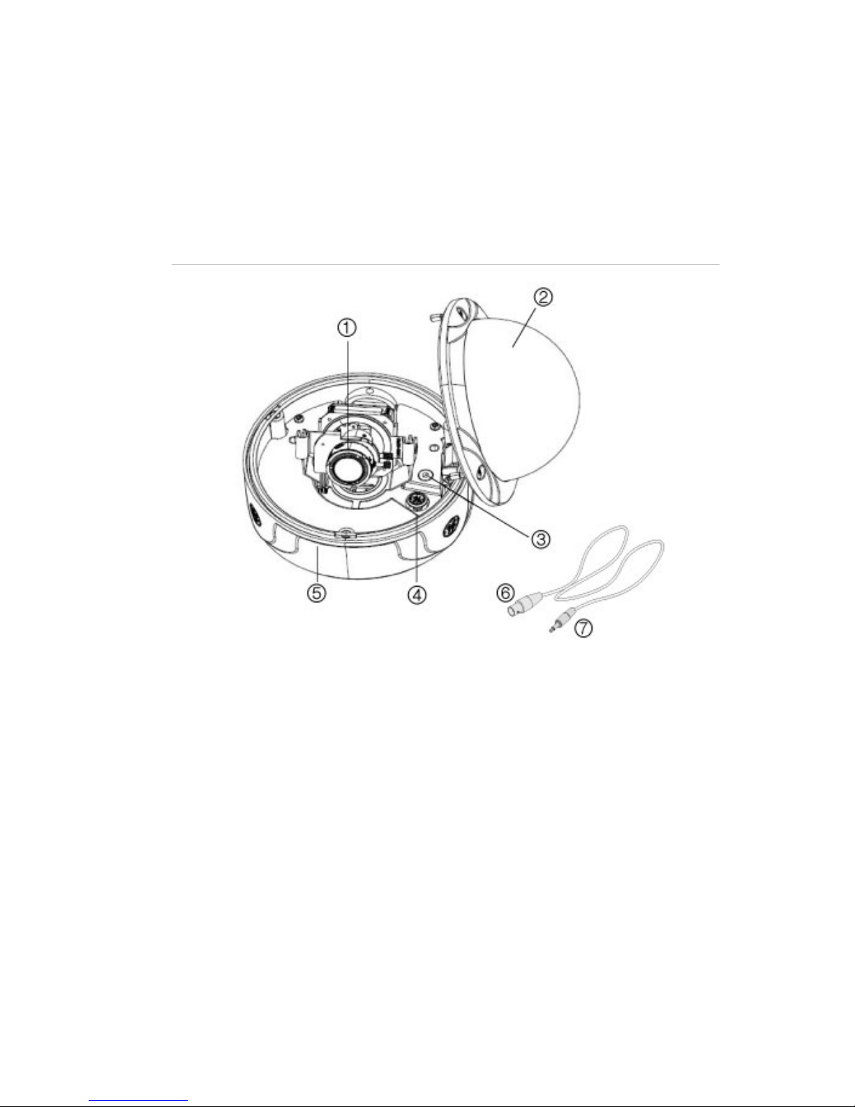
The UVD-XP4DNR(-P) camera consists of the following parts:
• The camera assembly
• Monitor output cable
• Mounting screws, wall anchors, and hex key
Figure 1: The camera assembly and monitor output cable
1. Lens body 5. Camera body
2. Bubble 6. Monitor output BNC
3. Video monitor output 7. Monitor output RCA
4. OSD control pad
Use the video output BNC and power jack for normal system
operation. Use the monitor output cable for installation and
maintenance.
OSD control pad
The onscreen display (OSD) control pad is a five-direction joystick that
provides the ability to manually control the camera functions.
Page 4

EN 4 Quick Start Guide
OSD control pad
Table 1 lists the OSD control pad functions and describes their use.
Table 1: OSD control pad functions
Pad directions Description
Up Moves the cursor upward to select an item.
Left
Moves the cursor left to select or adjust the parameters
of the selected item.
Right
Moves the cursor to the right to select or adjust the
parameters of the selected item.
Down Moves the cursor downward to select an item.
Enter
Press the center of the control pad to display the Setup
menu. If the selected item has its own menu, press the
control pad to enter a submenu. Press the control pad for
2 seconds to save all settings and exit the Setup menu.
Installation
Complete all the necessary programming before you install the
camera. This section provides information on how to install the camera
and adjust camera angle and focus.
WARNING: To reduce the risk of fire or electronic shock, do not
expose the camera to rain or moisture and do not remove the cover or
back.
Cable connection
To make cable connections, do the following:
1. Connect a coaxial cable from the camera’s BNC connector to a
CCTV monitor or video recording device.
2. Connect a 12 VDC or 24 VAC power supply to the power input.
The label on the camera gives the following information:
Red cable. Power in.
Black cable. Power in.
Page 5

Quick Start Guide 5 EN
White cable. Video out.
Black cable. Video ground.
Note: For AC24V or DC12V, Black or Red may be used for ground.
Camera installation
To mount the camera, attach the camera to the mounting surface using
the appropriate fasteners.
Angle adjustment
To adjust the horizontal angle of the platform up to 180 degrees, turn
the platform (1).
To adjust the horizontal angle of the rotor up to 350 degrees, turn the
rotor on the platform (2).
To adjust the vertical angle of the platform up to 90 degrees, turn the
platform (3).
Focus adjustment
To adjust the camera zoom and focus:
Page 6

EN 6 Quick Start Guide
1. Zoom ring thumbscrew for VA2 and focus ring for VA9 lens.
2. Focus ring thumbscrew for VA2 and zooming ring for VA9 lens.
1. Loosen the zoom ring thumbscrew.
2. Turn the zoom ring to set the desired zoom.
3. Tighten the zoom ring thumbscrew.
4. Loosen the focus ring thumbscrew.
5. Turn the focus ring to set the desired focus.
6. Tighten the focus ring thumbscrew.
Connect the monitor
Program the cameras by attaching a standard video monitor to the
system.
To connect the monitor, do the following:
1. Plug the monitor output cable to the video monitor output
connector.
2. Connect the BNC cable to the video monitor.
3. Press the OK button to display the Setup menu.
Programming
The camera is configured through the setup menus which appear onscreen. See Figure 2.
Figure 2: Main menu
To access and navigate the menus, press and hold the center of the
OSD control pad. Press Up or Down on the control pad to move
between items, and press Enter (center of the control pad) to select the
Page 7

Quick Start Guide 7 EN
item. Press Right or Left on the control pad to select the different
options available for the item.
You can return to the previous menu from any of the menus (except
the Main menu) by selecting the Previous page option.
The menu map is shown on the back page of this manual.
Refer to the User Manual for detailed programming instructions.
Table 2: Main menu options
Menu option Description
Preset Preset settings.
Setup Camera ID, Line Lock, motion detection, and WDR settings.
Viewing Flip and resolution settings
Exposure
AGC, AE preferences, range control, shutter limit, frame
RPT, and B/W control settings.
White balance White balance settings.
Save/Restore Save and restore user and factory settings.
Specifications
Electrical
Power Input 12 VDC or 24 VAC
Power consumption 3W (DC); 2.4 W (AC)
Environmental and physical
Weight 33.8 oz. (958 g)
Dimensions 5.22 x 4.11 in. (133 x 105 mm)
Operating Temperature -58 to +122°F (-50 to +50°C)
Weather resistant IP66
Page 8

EN 8 Quick Start Guide
 Loading...