

Page 1
UltraView UVD-6130VE-2 WDR Dome Camera
Quick Start Guide
Introduction
This is the Quick Installation Guide for the UVD-6130VE-2 WDR color
dome camera.
Refer to the user manual for complete instructions on installing and
configuring this camera.
User guidelines
• Program the camera settings as much as possible before
mounting the camera. Take appropriate safety precautions while
completing programming after installation.
• Always use a 12 VDC or 24 VAC UL listed Class 2 power supply
to power the camera.
• Do not use the camera over the temperature range specifications:
- 22 to 122°F (-30 to +50°C)
• If the light source where the camera is installed experiences
rapid, wide- variations in lighting, the camera may not operate as
intended.
WARNING: To reduce the risk of fire or electronic shock, do not
expose the camera to rain or open the back of the camera.
Description
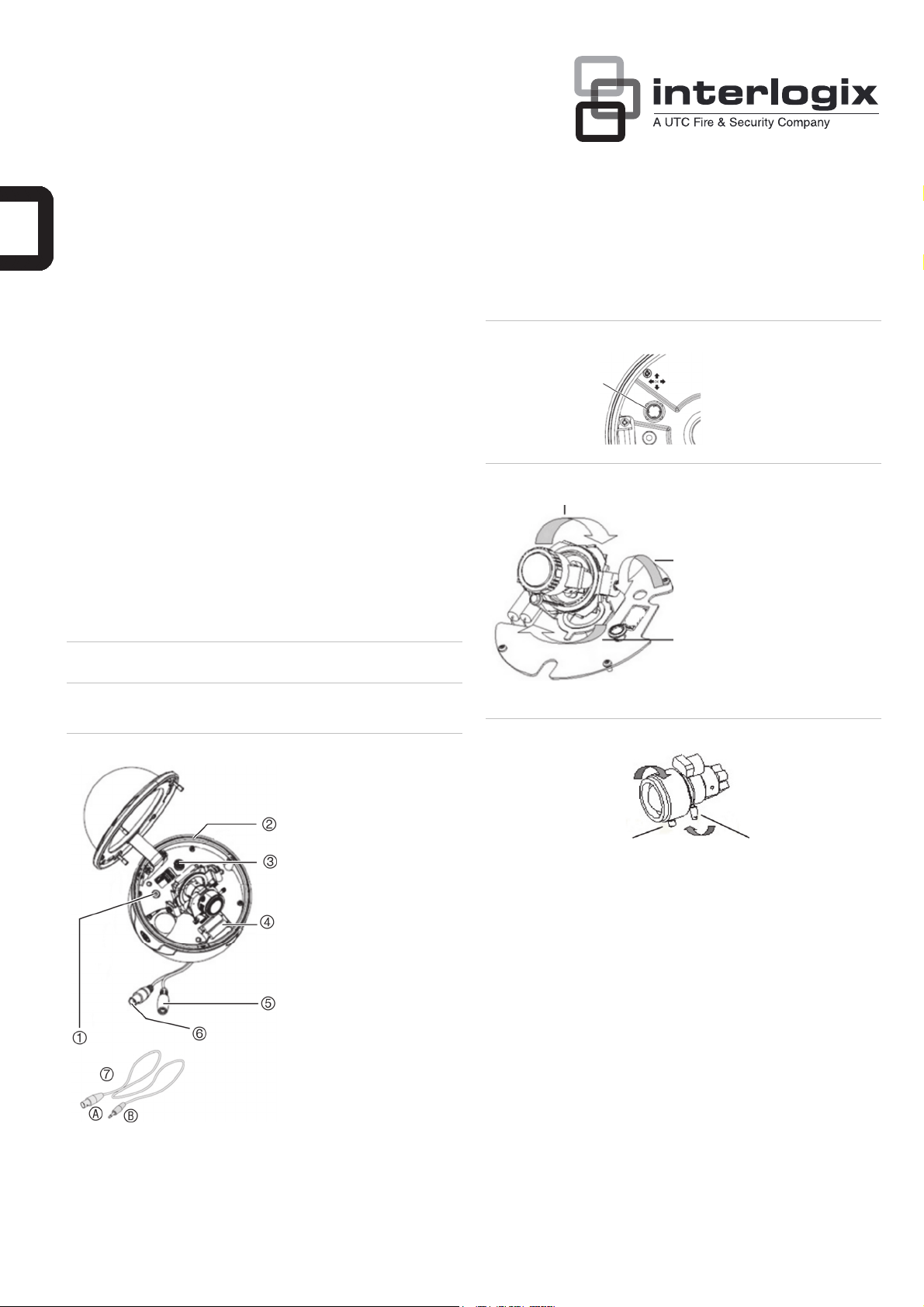
Figure 1: Camera description
1. Video monitor output
2. Camera body
3. OSD control pad
4. System heater
5. Power jack
6. Video output BNC
7. Monitor output cable
used during camera
installation: A. Monitor
output BNC; B. Monitor
output RCA.
Figure 2: OSD control pad
OSD control pad
Figure 3: Camera adjustment
Platform horizontal adjustment
Figure 4: Zoom and focus adjustment
Zoom ring thumbscrew Focus ring thumbscrew
Platform vertical adjustment
Rotor horizontal adjustment
Installation
Please check the package contents and make sure that the device in
the package is in good condition and all the assembly parts are
included.
Note: Before installing, please ensure that the mounting surface is
strong enough to withstand three times the weight of the camera. If the
wall is not strong enough, the camera may fall and cause serious
damage.
Install the camera
1. Mount the camera.
Use the ceiling drilling holes template and mark the holes on the
ceiling with a pen. Attach the plate with fasteners to the ceiling
and then attach the camera body to the plate. To mount the
camera, attach the camera to the mounting surface using the
appropriate fasteners
2. Connect the cables.
© 2012 UTC Fire & Security. All rights reserved. 1 / 2 P/N 1072550A • ISS 18JUN12
Page 2
Connect a coaxial cable from the camera’s BNC connector to a
CCTV monitor or video recording device. Connect a 12 VDC or
24 VAC power supply to the power input of the camera.
Caution: Check for polarity when using a 12 VDC power supply.
3. Adjust the lens (see Figure 3).
To adjust the horizontal angle of the platform up to 180 degrees,
turn the platform.
To adjust the horizontal angle of the rotor up to 350 degrees, turn
the rotor on the platform.
To adjust the vertical angle of the platform up to 90 degrees, turn
the platform.
4. Adjust the focus and zoom of the camera by using the zoom and
focus ring thumbscrews (see Figure 4).
5. Secure the dome cover with screws.
Programming
Once the camera hardware has been installed, the camera can then
be configured. Program the camera by attaching a standard video
monitor to the system.
OSD control pad
The on-screen display (OSD) control pad (see Figure 1) is a fivedirection button that lets you manually control the camera functions.
Table 1 below lists the OSD control pad functions and describes their
use.
Specifications
Model UVD-6130VE-2-P / UVD-6130VE-2-N
Lens type Varifocal: 2.8 to 10 mm
Power supply 24 VAC / 12 VDC
Current 300 mA
Max: 450 mA (heater on)
Power consumption 3.6 W
Max: 10.8 W (heater on)
Operating temperature -30 to +50 °C (-22 to 122 °F)
Weight 1130 g (2.49 lbs)
Dimensions (H × Ø) 105 ×133 mm (4.11 × 5.22 in.)
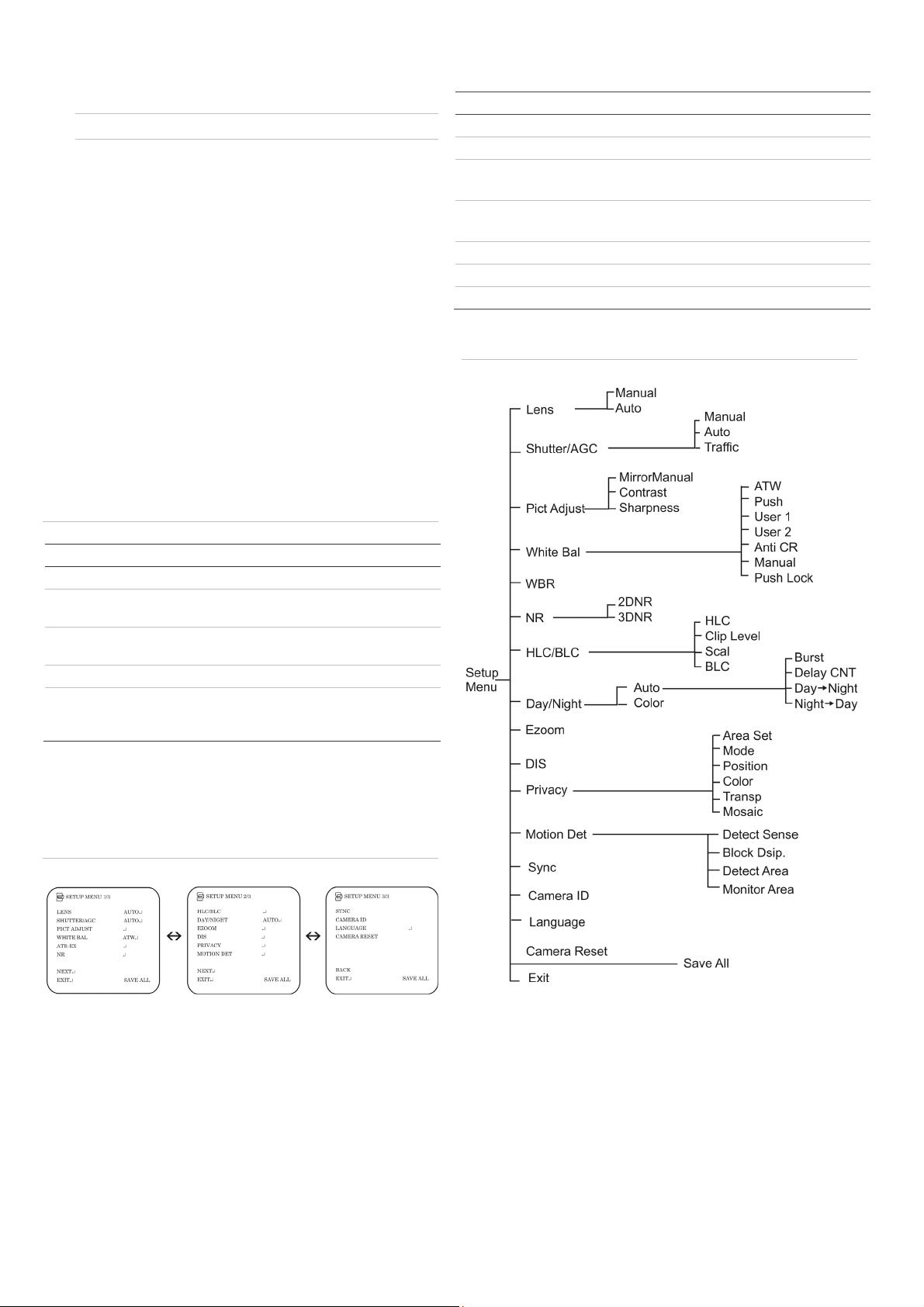
Menu map
Figure 6: Menu map
Table 1 Description of the OSD control pad
Pad direction Description
Up Moves the cursor upward to select an item
Left Moves the cursor left to select or adjust the options
of the selected item.
Right Moves the cursor to the right to select or adjust the
options of the selected item.
Down Moves the cursor downward to select an item.
Enter Press the center of the control pad to display the
Setup menu. If the selected item has its own menu,
press the control pad to enter a submenu.
Accessing the menus
Press Enter on the camera’s OSD control pad to display the Setup
menu (see Figure 5 below). The Setup menu provides access to the
camera configuration options (Figure 6). The OSD display is only
available in English.
Figure 5: The Setup menu screen
To access the Main menu:
1. Press the OSD control pad to access the Setup menu and its
submenus.
2. Push the pad up/down to move between menu options.
3. Push the pad left/right to select an option.
4. When in a sub menu, select Return to return to the previous
menu.
5. To save configuration changes, move the cursor to Save All at
the bottom of the screen and press Enter
6. To exit a menu and return to live mode, move the cursor to Exit at
the bottom of the screen and press Enter.
2 / 2 P/N 1072550A • REV 1.0 • ISS 18JUN12
 Loading...