

Page 1
TruVision TVT-2101/ TVT-4101 IR Turret
Camera Installation Instructions
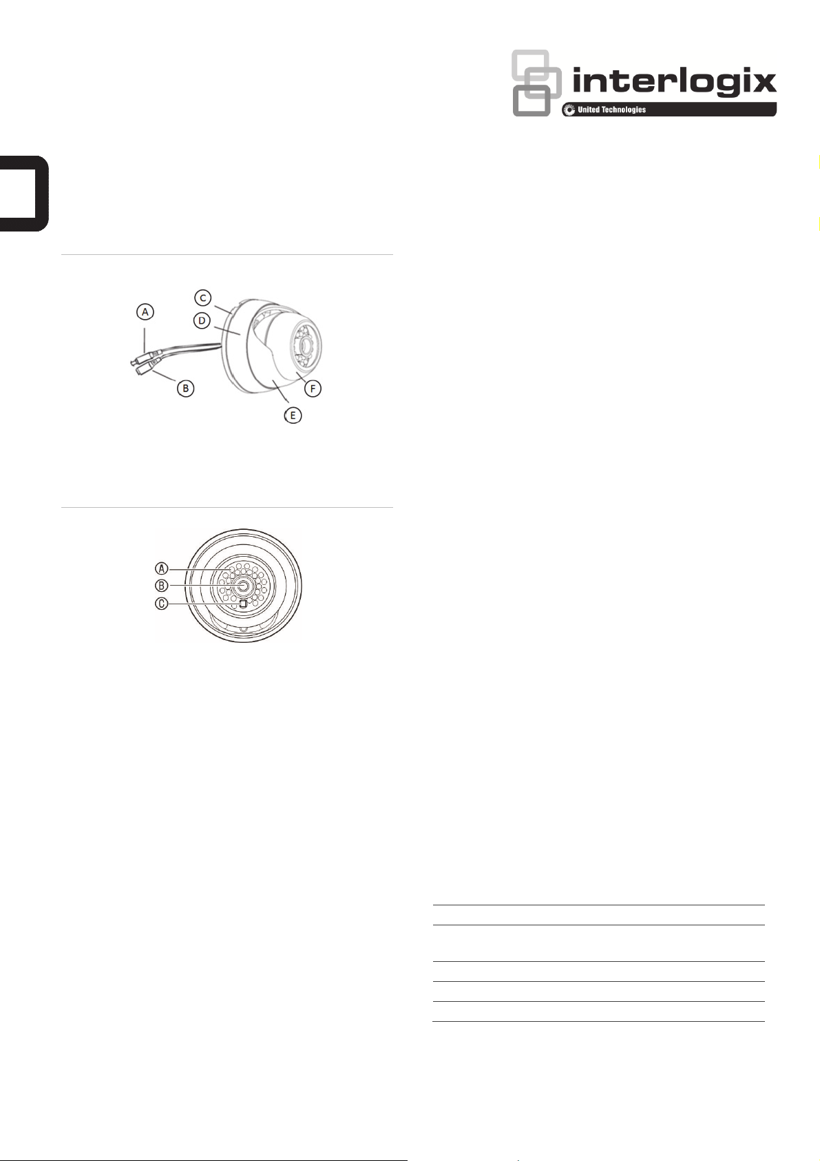
Figure 1: Parts of the camera
A. Video cable
B. Power cable
C. Mounting bracket
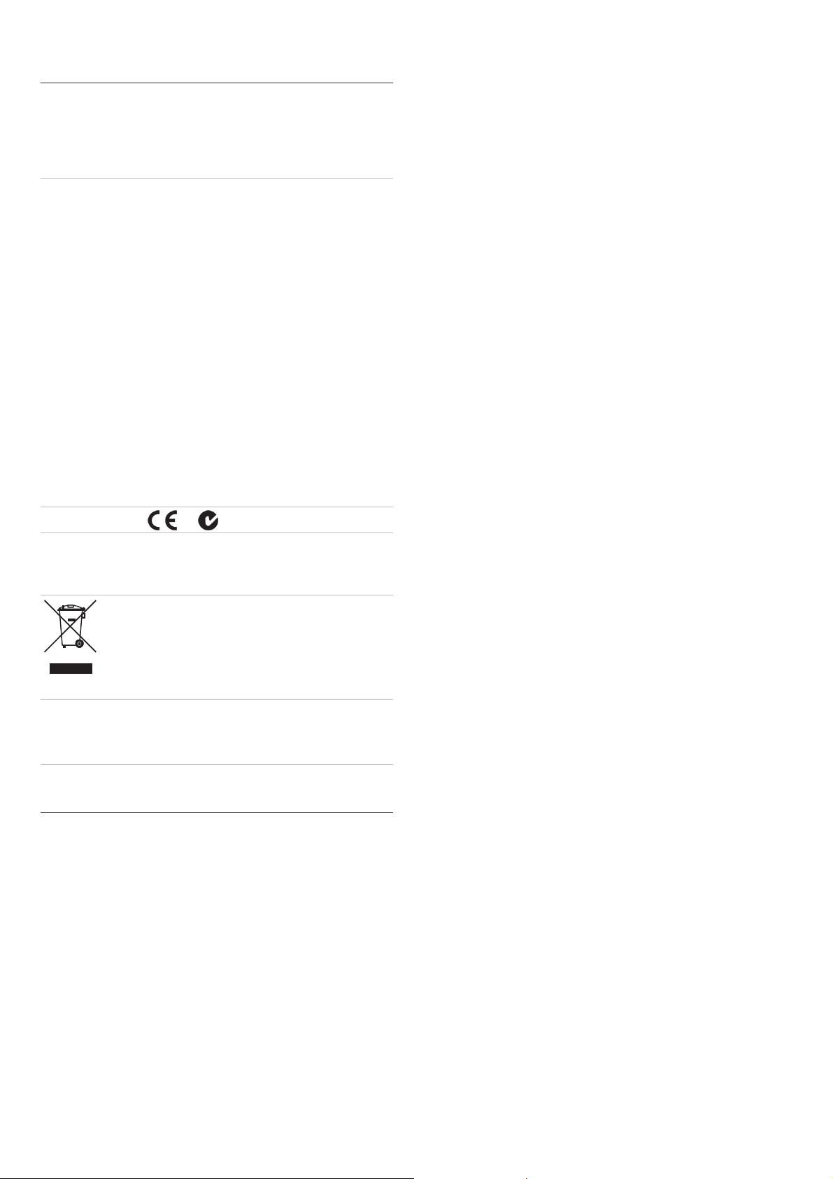
Figure 2: Camera front
LED IR lights; B. Lens; C. Light sensor
Overview
D. Fixed ring
E. Shroud
F. Camera
Installation
When installing the camera, please use the mounting bracket
as a template.
To install the camera:
1. Unscrew the fixed ring and shroud assembly from the
camera.
2. Using the mounting bracket as a template, place it level
against the mounting surface and mark the position of the
mounting holes.
3. Following all local codes, drill and prepare the mounting
holes.
4. Route the camera’s cable through the mounting bracket,
and then install the mounting bracket with the four
provided screws. If your mounting surface requires it, use
the provided wall anchors or other appropriate fasteners.
5. While holding the camera in position, place the fixed ring
and shroud over the camera and tighten.
6. Adjust the camera position.
7. Connect a 75-ohm coaxial video cable to the camera’s
video cable, and connect a 12 VDC power supply to the
power cable.
Note: When installing the camera, tilting the camera housing
past 80° may result in reflection of IR illumination from the
camera base into the lens. This can distort or obscure the
picture in night mode.
These are the TruVision IR Turret Camera installation
instructions for TVT-2101/4101. The instructions describe a
standard installation.
The camera consists of the following:
Camera with power and video output cables
Camera shroud
Fixed ring to secure the camera and camera shroud to the
mounting bracket
One dual-power terminal block with its screw and anchor
4 anchors and 4 screws for wall or ceiling installation
Refer to Figures 1 and 2 when performing the camera setup
procedures.
P/N 1072700B-EN • REV 1.0 • ISS 17OCT13 1 / 2
8. Check the picture and adjust the camera position and
angle as required.
9. Tighten the fixed ring to secure it to the mounting bracket.
Ensure that the camera shroud is firmly attached to the
bracket.
Specifications
Power supply 12 VDC
Current 80 mA (IR Off)
200 mA (IR On)
Power consumption 2.4 W max.
Weight 0.86 lb. (390 g)
Dimensions (H × Ø) 2.7 x 3.7 (69 x 94 mm)
Page 2
Regulatory information
Manufacturer United Technologies Corporation.
FCC compliance Class B: This equipment has been tested and found to
Certification
European Union
directives
Copyright
Trademarks and
patents
2955 Red Hill Avenue, Costa Mesa, CA 92626 5923,
USA
Authorized EU manufacturing representative:
UTC Climate Controls & Security B.V.
Kelvinstraat 7, 6003 DH Weert, The Netherlands
comply with the limits for a Class B digital device,
pursuant to part 15 of the FCC Rules. These limits are
designed to provide reasonable protection against
harmful interference in a residential installation. This
equipment generates, uses, and can radiate radio
frequency energy and, if not installed and used in
accordance with the instructions, may cause harmful
interference to radio communications.
There is no guarantee that interference will not occur in
a particular installation. If this equipment does cause
harmful interference to radio or television reception,
which can be determined by turning the equipment off
and on, the user is encouraged to try to correct the
interference by one or more of the following measures:
• Reorient or relocate the receiving antenna.
• Increase the separation between the equipment and
receiver.
• Connect the equipment into an outlet on a circuit
different from that to which the receiver is connected.
• Consult the dealer or an experienced radio/TV
technician for help.
N4131
12004/108/EC (EMC directive): Hereby, UTC Climate
Controls & Security declares that this device is in
compliance with the essential requirements and other
relevant provisions of Directive 2004/108/EC.
2002/96/EC (WEEE directive): Products marked with this
symbol cannot be disposed of as unsorted municipal
waste in the European Union. For proper recycling,
return this product to your local supplier upon the
purchase of equivalent new equipment, or dispose of it
at designated collection points. For more information
see: www.recyclethis.info.
© 2013 United Technologies Corporation.
Interlogix is part of UTC Climate Controls & Security, a
unit of United Technologies Corporation. All rights
reserved.
Trade names used in this document may be trademarks
or registered trademarks of the manufacturers or
vendors of the respective products.
Contact information
For contact information, see www.interlogix.com or
www.utcfssecurityproducts.eu.
2 / 2 P/N 1072700B-EN • REV 1.0 • ISS 17OCT13
 Loading...