

Page 1

TruVision HD
Camera Installation
Configuration Man
P/N 1073359-EN • REV B • ISS 22AUG17
-TVI 5MPX
and
ual
Page 2

Page 3

Contents
Introduction 5
Product overview 5
HD-TVI fixed lens bullet camera: 5
HD-TVI VF motorized lens bullet camera: 5
HD-TVI fixed lens turret camera: 5
HD-TVI VF motorized lens turret camera: 6
HD-TVI VF motorized lens dome camera: 6
Installation 7
Installation environment 7
Package contents 10
HD-TVI fixed lens bullet camera 10
HD-TVI VF motorized lens bullet camera 12
HD-TVI fixed lens turret camera 14
HD-TVI VF motorized lens turret camera 17
HD-TVI VF motorized lens dome camera 19
Camera description 22
Mounting the HD-TV I fixed lens bullet camera 28
Installation and Configuration Manual 1
Page 4

Surface mount 28
Surface mount when using the optional back
box 30
Mounting the HD-TV I VF motorized lens bullet
camera 34
Surface mount when not using the supplied
back box 34
Surface mount when using the back box 37
Mounting the HD-TVI fixed lens turret camera 40
Surface mount 40
Surface mount when using the optional back
box 45
Mounting the HD-TV I VF motorized lens turret
camera 48
Surface mount 48
Surface mount when using the optional back
box 53
Mounting the HD-TV I VF motorized lens dome
camera 57
Surface mount 57
2 Installation and Configuration Manual
Page 5

Programming 61
Call up the camera OSD menu 62
Menu trees 64
TVB-2409/4409 and TVT-2403/4403 cameras 65
TVB-2410/4410, TVT-2404/4404, and TVD-
2406/4406 cameras 66
Configuration 67
Output Mode 67
Focus 69
Language 69
Main Menu 70
Exposure 70
White Balance 74
Day/Night 75
Video Settings 77
Reset 79
Save & Exit 79
Installation and Configuration Manual 3
Page 6

Specifications 80
Legal and regulatory information 83
4 Installation and Configuration Manual
Page 7

Introduction
Product overview
This is the installation guide for TruVision
5MPX HD-TVI camera models:
HD-TVI fixed lens bullet camera:
TVB-2409 (5MPX Bullet, 3.6 mm lens, PAL)
TVB-4409 (5MPX Bullet, 3.6 mm lens,
NTSC)
HD-TVI VF motorized lens bullet
camera:
TVB-2410 (5MPX Bullet, 2.8 to 12 mm lens,
PAL)
TVB-4410 (5MPX Bullet, 2.8 to 12 mm lens,
NTSC)
HD-TVI fixed lens turret camera:
TVT-2403 (5MPX Turret, 2.8 mm lens, PAL)
TVT-4403 (5MPX Turret, 2.8 mm lens,
NTSC)
Installation and Configuration Manual 5
Page 8

HD-TVI VF motorized lens turret
camera:
TVT-2404 (5MPX Turret, 2.8 to 12 mm lens,
PAL)
TVT-4404 (5MPX Turret, 2.8 to 12 mm lens,
NTSC)
HD-TVI VF motorized lens dome
camera:
TVD-2406 (5MPX Dome, 2.8 to 12 mm lens,
PAL)
TVD-4406 (5MPX Dome, 2.8 to 12 mm lens,
NTSC)
6 Installation and Configuration Manual
Page 9

Installation
This section provides information on how to
install the cameras.
Installation environment
Please keep in mind that there are
restrictions/rules when using the HD-TVI
5MPX cameras with TruVision TVI recorders:
The TVI 5MPX cameras only work with the
higher resolution TVI recorders (TVR 15HD
or TVR 45HD, or higher), firmware version
1.1 (or higher)
A maximum number of TVI 5MPX cameras
can be supported per TVI recorder
The TVI 5MPX cameras are only supported
on specific ports of the TruVision TVI
recorders
Installation and Configuration Manual 7
Page 10

Guidelines:
TVR 15HD four-channel recorder, v1.1:
Supports a maximum of one TVI 5MPX
camera on BNC port 1
TVR 15HD/TVR 45HD eight-channel
recorder, v1.1: Supports up to two TVI
5MPX cameras on BNC ports 1 and 2
TVR 15HD/TVR 45HD 16-channel recorder,
v1.1: Supports up to four TVI 5MPX
cameras on BNC ports 1, 2, 3 and 4
When installing your product, consider these
factors:
• Electrical: Install electrical wiring carefully.
It should be done by qualified service
personnel. Always use a proper 12 VDC or
24 VAC UL listed Class 2 or CE certified
power supply to power the camera. Do not
overload the power cord or adapter.
• Ventilation: Ensure that the location
planned for the installation of the camera is
well ventilated.
8 Installation and Configuration Manual
Page 11

• Temperature: Do not operate the camera
beyond the specified temperature, humidity
or power source ratings. The operating
temperature of the camera is between -40 to
+60°C (-40 to +140°F). Humidity is below
90% (non-condensing).
• Moisture: Do not expose the camera to rain
or moisture, or try to operate it in wet areas.
Turn the power off immediately if the
camera is wet and ask a qualified service
person for servicing. Moisture can damage
the camera and also create the danger of
electric shock.
• Servicing: Do not attempt to service this
camera yourself. Any attempt to dismantle
this product will invalidate the warranty and
may also result in serious injury. Refer all
servicing to qualified service personnel.
• Cleaning: Do not touch the sensor modules
with fingers. If cleaning is necessary, use a
clean cloth with some ethanol and wipe the
camera gently. If the camera will not be
used for an extended period of time, put on
the lens cap to protect the sensors from dirt.
Installation and Configuration Manual 9
Page 12
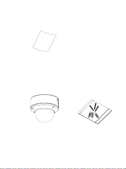
Package contents
Check the package and contents for visible
damage. If any components are damaged or
missing, do not attempt to use the unit; contact
the supplier immediately. If the unit is returned,
it must be shipped back in its original
packaging.
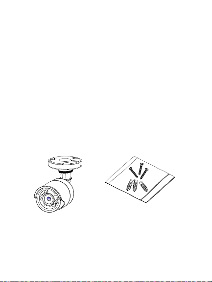
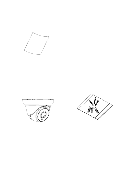
HD-TVI fixed lens bullet camera
Camera with power
and video output
cable harness
(cables not shown)
3 screws (4 ×
25 mm) and 3
anchors (7.5 ×
24.5 mm)
10 Installation and Configuration Manual
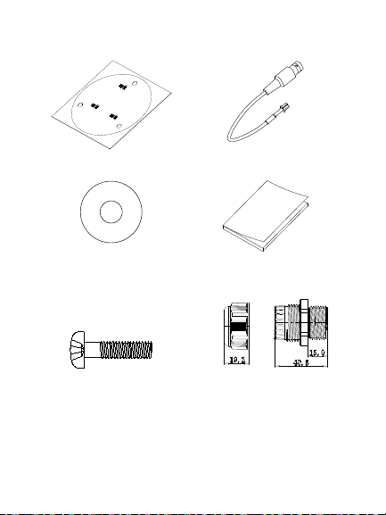
Page 13
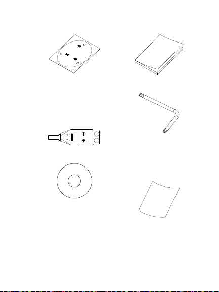
Mounting template Installation guide
• 12 VDC connector:
Two terminal
connector with
positive and
negative indicators
• Torx wrench
• CD
• Equipment
disposal sheet
(WEEE directive)
Installation and Configuration Manual 11
Page 14
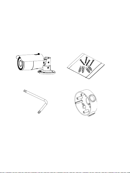
HD-TVI VF motorized lens bullet
camera
Camera with power
and video output
cable harness
(cables not shown)
4 screws (4 ×
25 mm) and 4 (7.5
× 24.5 mm)
anchors
• Torx wrench
• Back box
12 Installation and Configuration Manual
Page 15
Ceiling Mounting
1
1
1
1
2
2
2
2
1:Screw Hole for
Bracket
2:Screw Hole for
Mounting Base
(mm)
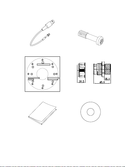
• Video test cable • 4 scre ws (M4.8 ×
18). Used with the
back box
Mounting template
• Plastic G3/4 cable
adapter
Installation guide • CD
Installation and Configuration Manual 13
Page 16
• Equipment
disposal sheet
(WEEE directive)
HD-TVI fixed lens turret camera
Camera with power
and video output
cable harness
(cables not shown)
• 3 screws (4 × 25 mm)
and 3 anchors (7.5 ×
24.5 mm)
14 Installation and Configuration Manual
Page 17
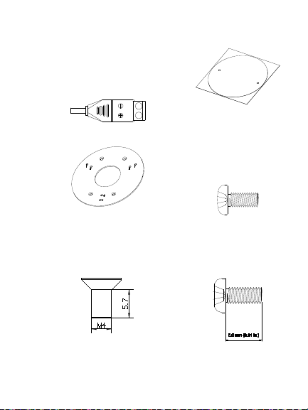
• 12 VDC connector:
Two terminal
connector with
positive and
negative indicators
• Adapter plate
Mounting template
4 screws (PM6-32 ×
10). Used to attach
the turret camera to a
2 gang electrical box
4 screws (KM4 × 8).
Used to attach the
turret camera to the
bracket
3 screws (PM4 × 8).
Used to attach the
turret camera to the
adapter)
Installation and Configuration Manual 15
Page 18

• CD
Installation guide
• Equipment disposal
sheet (WEEE
directive)
16 Installation and Configuration Manual
Page 19
HD-TVI VF motorized lens turret
camera
Camera with power
and video output
cable harness
3 screws (4 ×
25 mm) and 3
anchors (7.5 ×
24.5 mm)
4 screws (KM4 x 8).
Used to attach turret
camera to bracket
4 screws (PM6-
32 × 10). Used
to attach the
turret camera to
a 2 gang
electrical box
Installation and Configuration Manual 17
Page 20
• 12 VDC connector:
Two-terminal
connector with
positive and negative
indicators
Template
• CD
3 screws (PM4 x
8). Used to
attach the turret
camera to the
adapter)
Installation guide
Adapter plate
18 Installation and Configuration Manual
Page 21
• Equipment disposal
sheet (WEEE
directive)
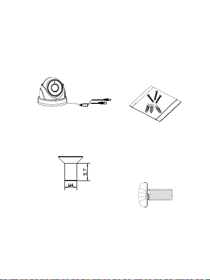
HD-TVI VF motorized lens dome
camera
Camera with power
and video output
cable harness
3 screws (4 ×
25 mm) and 3
anchors (7.5 ×
24.5 mm)
Installation and Configuration Manual 19
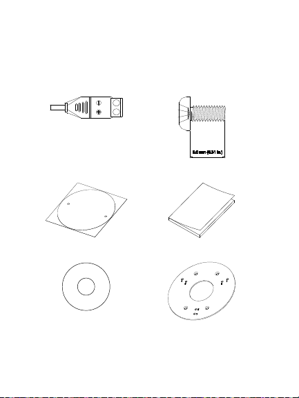
Page 22
Template
(mm)
• CD
• Video test cable
Installation guide
• 3 screws (PM4 × 16).
Used to install the
• Plastic G3/4 cable
adapter
camera body on to
the dome back box
20 Installation and Configuration Manual
Page 23

• Torx wrench
• Spare rubber
insert
• Equipment disposal
sheet (WEEE
directive)
Installation and Configuration Manual 21
Page 24
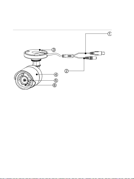
Camera description
3. Mounting base
6. IR LEDs
Figure 1: HD-TVI fixed lens bullet camera
1. TVI output
2. 12 VDC power
22 Installation and Configuration Manual
4. Camera body
5. Lens
Page 25
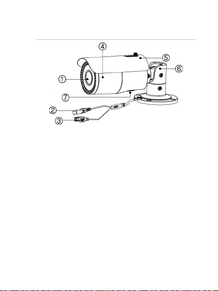
Figure 2: HD-TVI VF motorized lens bullet
4. Camera body
camera
1. Lens
2. TVI output
3. 12 VDC/24 VAC
power
Installation and Configuration Manual 23
5. Sunshield
6. Mounting base
7. Access to OSD
menu button and
TVI output
Page 26
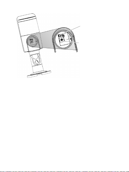
TVI output
OSD menu
button
Note: When making adjustments to the
motorized lens bullet camera, it is important to
tighten the access cover (7) for the area that
contains the video test cable connector and
OSD menu button. The access cover should
be rotated until it is tight up against the camera
body.
24 Installation and Configuration Manual
Page 27
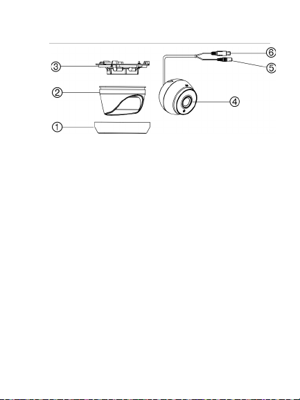
Figure 3: HD-TVI fixed lens turret camera
3. Base
6. TVI output
1. Trim ring
2. Housing
Installation and Configuration Manual 25
4. Lens assembly
5. 12 VDC power
Page 28
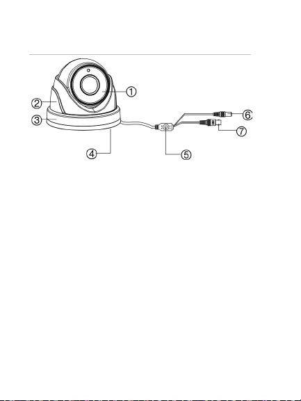
Figure 4: HD-TVI VF motorized lens turret
4. Base
camera
1. Lens assembly
2. Housing
3. Trim ring
5. OSD (5-direction)
button
6. 12 VDC power
7. TVI output
26 Installation and Configuration Manual
Page 29

Figure 5: HD-TVI VF motorized lens dome
4. TVI output
camera
1. Bubble
2. Video test cable
3. OSD (5-direction)
Installation and Configuration Manual 27
button
5. 12 VDC/24 VAC
power
6. Lens assembly
7. Base
Page 30

Mounting the HD-TVI fixed lens bullet camera
Surface mount
1. Place the provided template level against
the mounting surface and mark the
position of the mounting holes.
2. Following all local safety regulations, drill
and prepare the mounting and cable
access (if required) holes.
3. Route the cables through the cable access
slot.
4. Secure the camera to the surface with the
mounting hardware that was provided.
28 Installation and Configuration Manual
Page 31

Pan position range: 0-360°
P
T
R
adjustment
range: 360°
180°
5. Connect the corresponding cables.
6. Adjust the camera to get the best viewing
angle. See the figure below.
(pan) adjustment
(tilt) adjustment
(rotation)
Rotation position
Installation and Configuration Manual 29
Tilt position range: 0-
Page 32

a) Loosen the P adjustment disk to
adjust the pan direction [0-360°].
Tighten the disk after completing the
adjustment.
b) Loosen the T screw to adjust the tilt
direction [0-180°]. Tighten the screw
after completing the adjustment.
c) Loosen the R screw and rotate the
camera [0-360°] to adjust the lens to
the desired surveillance angle.
Tighten the screw after completing the
adjustment.
Surface mount when using the
optional back box
Note: The fixed lens bullet back box or two
gang adapter plate are supplied separately.
1. Remove the cover from the back box and
align the screw holes of the bullet camera
with the holes in the back box cover.
30 Installation and Configuration Manual
Page 33

2. Route the cables through the cable access
hole of the back box. Mount the camera to
the back box cover using the screws
provided.
3. Place the mounting template level against
the mounting surface and mark the
position of the mounting holes. Use the
‘UP’ marking on the back box and camera
mounting base as a reference.
Installation and Configuration Manual 31
Page 34

4. Following all local safety regulations, drill
and prepare the mounting holes.
5. Install the back box to the mounting
surface using the hardware provided.
32 Installation and Configuration Manual
Page 35

6. Connect the corresponding cables, and
install the back box cover and camera to
the back box.
7. Refer to step 6 of “Surface mount” on
page 28 to adjust the camera viewing
angle.
Installation and Configuration Manual 33
Page 36

Mounting the HD-TVI VF motorized lens bullet camera
Surface mount when not using the
supplied back box
1. Use the supplied template to mark out the
mounting area.
2. Following all local safety regulations, drill
and prepare the mounting and cable
access (if required) holes.
3. Route the cables through the cable access
hole.
34 Installation and Configuration Manual
Page 37

4. Secure the camera to the mounting
surface with the provided hardware.
5. Connect the corresponding cables.
6. Adjust the camera to get the best viewing
angle. See the figure below.
Installation and Configuration Manual 35
Page 38

P (pan) adjustment
T (tilt) adjustment
R (rotation)
adjustment
a) Loosen the P screw to adjust the pan
direction [0-360°]. Tighten the screw
after completing the adjustment.
b) Loosen the T screw to adjust the tilt
direction [0-180°]. Tighten the screw
after completing the adjustment.
c) Loosen the R screw and rotate the
camera [0-360°] to adjust the lens to
the desired surveillance angle.
Tighten the screw after completing the
adjustment.
36 Installation and Configuration Manual
Page 39

Surface mount when using the back
box
1. Remove the cover from the back box and
align the screw holes of the bullet camera
with the holes in the back box cover.
2. Route the cables through the cable access
hole of the back box. Install the camera to
the back box cover using the screws
provided. See figure below.
Installation and Configuration Manual 37
Page 40

3. Place the provided template level against
the mounting surface and mark the
position of the mounting holes.
4. Following all local safety regulations, drill
and prepare the mounting holes.
5. Install the back box to the mounting
surface using the hardware provided.
38 Installation and Configuration Manual
Page 41

6. Connect the corresponding cables and
install the camera to the back box.
7. Refer to step 6 of “Surface mount when
not using the supplied back box” on page
Installation and Configuration Manual 39
Page 42

34 to adjust the camera to the desired
viewing angle.
Mounting the HD-TVI fixed lens turret camera
Surface mount
1. Disassemble the turret camera by rotating
the trim ring, as shown below.
2. Place the provided template level against
the mounting surface and mark the
position of the mounting holes.
40 Installation and Configuration Manual
Page 43

3. Following all local safety regulations, drill
and prepare the mounting and cable
holes.
4. Route the cables through the cable access
hole (if required).
5. Secure the mounting base to the mounting
surface with the hardware provided.
Installation and Configuration Manual 41
Page 44
6. Route the cables. Connect the power cord
and TVI cables.
7. Reassemble the turret camera by rotating
the trim ring back in place.
If installing the turret camera to a wall
mount or other accessory, an adapter
plate is provided. Install the adapter plate
42 Installation and Configuration Manual
Page 45

to the accessory with three PM4 x 8
screws, referencing number "2".
8. Adjust the camera to get the best viewing
angle. See figure below.
Installation and Configuration Manual 43
Page 46

Pan position range: 0-360°
Tilt position range:
0-75°
Rotation position
range: 0-360°
a) Hold the camera body and rotate the
enclosure to adjust the pan angle [0-
360°].
b) Move the camera body up and down
to adjust the tilt angle [0-75°].
c) Rotate the camera body to adjust the
azimuth angle [0-360°].
44 Installation and Configuration Manual
Page 47

Surface mount when using the
optional back box
1. Disassemble the turret camera by rotating
the trim ring, as shown below.
2. Remove the cover from the back box.
3. Place the provided template level against
the mounting surface and mark the
position of the mounting holes.
4. Following all local safety regulations, drill
and prepare the mounting holes.
Installation and Configuration Manual 45
Page 48

5. Route the cables through the cable access
hole of the back box. Mount the camera to
the cover of the back box.
6. Mount the back box to the mounting
surface.
46 Installation and Configuration Manual
Page 49

7. Connect the corresponding cables and
install the back box cover, with the
camera, to the back box.
8. Rotate the trim ring back on to the
camera, as shown below.
Installation and Configuration Manual 47
Page 50

9. Refer to page 43 to adjust the camera to
the desired viewing angle.
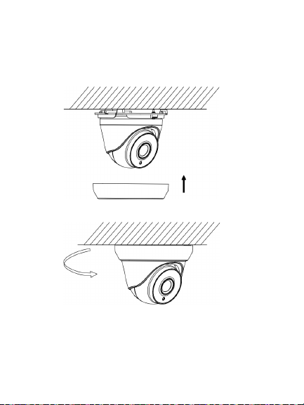
Mounting the HD-TVI VF motorized lens turret camera
Surface mount
1. Place the provided template level against
the mounting surface and mark the
position of the mounting holes.
2. Following all local safety regulations, drill
and prepare the mounting holes.
48 Installation and Configuration Manual
Page 51

3. Disassemble the turret camera by rotating
the trim ring counterclockwise, as shown
below.
4. Route the cables through the cable access
hole (if required).
5. Secure the mounting base to the surface
using the screws provided.
Installation and Configuration Manual 49
Page 52

There is an adapter plate provided if
installing the turret camera to a wall mount
or other accessory. Install the adapter
plate to the accessory with three PM4 x 8
screws, referencing number "2".
50 Installation and Configuration Manual
Page 53

6. Reassemble the turret camera by rotating
the trim ring back on the camera, as
shown below.
Helpful hints when mounting the turret
camera:
a) Mount the turret base to a surface.
b) When mounting on a wall, aim the
lens towards the floor and the UP
marking on the camera assembly
towards the ceiling.
c) Place the camera eyeball assembly
on two of the three standoffs of the
mounting base.
Installation and Configuration Manual 51
Page 54

d) Place the turret housing over the
camera assembly.
e) Place the metal ring over the camera
turret housing.
f) Hold the turret housing and camera
assembly in place with your right
hand.
g) Using your left hand, rotate the metal
ring clockwise to tighten it.
h) Prior to completely tightening the ring,
aim the camera body/lens towards the
desired position.
7. Adjust the camera to get the best viewing
angle (see figures below).
a) Hold the camera body and rotate the
enclosure to adjust the pan angle [0-
360°].
b) Move the camera body up and down
to adjust the tilt angle [0-75°].
52 Installation and Configuration Manual
Page 55

c) Rotate the camera body to adjust the
azimuth angle [0-360°].
Pan position range:
0-360°
Tilt position range:
0-75°
Rotation position range: 0-360°
Surface mount when using the
optional back box
1. Remove the cover from the back box.
2. Place the provided template level against
the mounting surface and mark the
position of the mounting holes.
Installation and Configuration Manual 53
Page 56

3. Following all local safety regulations, drill
and prepare the mounting holes.
4. Disassemble the turret camera by rotating
the trim ring counterclockwise, as shown
below.
54 Installation and Configuration Manual
Page 57

5. Route the cables through the cable access
hole of the back box. Mount the camera to
the back box.
6. Install the back box to the mounting
surface using the hardware provided.
Installation and Configuration Manual 55
Page 58

7. Connect the corresponding cables and
install the back box cover and camera to
the back box.
8. Rotate the trim ring back on to the camera
body, as shown by the arrow.
56 Installation and Configuration Manual
Page 59

9. Adjust the camera according to step 8 of
“Surface mount” on page 48 to get the
best vie wing angle.
Mounting the HD-TVI VF motorized lens dome camera
Surface mount
1. Place the provided template level against
the mounting surface and mark the
position of the mounting holes.
2. Following all local safety regulations, drill
and prepare the mounting holes.
Installation and Configuration Manual 57
Page 60

3. Loosen the three screws at the edge of
the bubble assembly using the supplied
Torx wrench.
4. Remove the bubble.
5. Secure the back box to the ceiling with the
supplied screws.
58 Installation and Configuration Manual
Page 61

Note: Please remove the rubber knockout
for cable routing outside of the camera,
when required.
6. Using a 75-ohm coaxial video cable,
connect the camera TVI video output and
a TVI DVR, and connect a 12 VDC or
24 VAC power supply to the power cable,
as indicated by the camera.
7. Align the camera assembly with the back
box. Use the three screws provided to
secure the camera body to the back box.
8. Adjust the surveillance angle:
a) View the camera image on a monitor.
Installation and Configuration Manual 59
Page 62

b) Rotate the panning table to adjust the
pan direction [0 to 355°].
c) Move the lens assembly up or down to
adjust the tilt position [0 to 90°].
d) Rotate the camera lens holder [0 to
355°] to adjust the lens to the
surveillance angle.
9. Reinstall the bubble assembly.
60 Installation and Configuration Manual
Page 63

Programming
Once the camera hardware has been installed,
configure the camera using the built-in OSD
button (if supported) and the TVI DVR menu.
The TVS-C200 controller (Service Tool) does
not support the 5MPX cameras.
You can also configure the camera settings via
a TVI DVR. Select the PTZ protocol TruVision
Coax and click the menu button to call up the
menu.
When using the TVI output, the 5MPX TVI
cameras must be used with the higher
resolution (5MPX or higher) TVI DVRs. They
are not compatible with lower resolution TVI
DVRs.
Please keep in mind that there are
restrictions/rules when using the HD-TVI
5MPX cameras with TruVision TVI recorders:
The TVI 5MPX cameras only work with the
higher resolution TVI recorders (TVR 15HD
or TVR 45HD, or higher), firmware version
1.1 (or higher)
Installation and Configuration Manual 61
Page 64

A maximum number of TVI 5MPX cameras
can be supported per TVI recorder
The TVI 5MPX cameras are only supported
on specific ports of the TruVision TVI
recorders
Guidelines:
TVR 15HD four-channel recorder, v1.1:
Supports a maximum of one TVI 5MPX
camera on BNC port 1
TVR 15HD/TVR 45HD eight-channel
recorder, v1.1: Supports up to two TVI
5MPX cameras on BNC ports 1 and 2
TVR 15HD/TVR 45HD 16-channel recorder,
v1.1: Supports up to four TVI 5MPX
cameras on BNC ports 1, 2, 3 and 4
Call up the camera OSD menu
To set up the camera:
1. Set up the camera hardware as described
in the Installation Manual.
2. In Camera Settings of the DVR, access
the PTZ menu and set the protocol for the
62 Installation and Configuration Manual
Page 65

TruVision HD-TVI camera to TruVision-
Coax.
3. In live view of the desired camera, click
the PTZ Control icon on the live view
toolbar to access the PTZ control panel.
4. To call up the camera setup menu:
From the camera, press the Menu button
(if present).
— or —
From the camera OSD of the DVR, select
Menu.
— or —
From the DVR, select Iris+.
The camera setup menu appears (see
“Menu trees” on page 64 for the menu
structure).
5. Select the menu options:
From the DVR: To select an OSD item,
click the directional buttons up/down. To
Installation and Configuration Manual 63
Page 66

adjust the value of a selected item, click
the directional buttons left/right.
From the camera (if it has a menu
button): To select an OSD item, push the
Menu button up/down. To adjust the value
of a selected item, push the Menu button
left/right.
6. Click Iris+ to enter the submenu or to
confirm the selected item.
7. When the setup is complete, select Exit
and click Iris+ to exit the camera OSD.
Note: You cannot exit the camera setup
menu using the Menu button on the
camera.
Menu trees
The menu trees of the TruVision TVI 5MPX
cameras are shown below.
64 Installation and Configuration Manual
Page 67

TVB-2409/4409 and TVT2403/4403 cameras
Installation and Configuration Manual 65
Page 68

TVB-2410/4410, TVT-2404/4404, and TVD-2406/4406 cameras
66 Installation and Configuration Manual
Page 69

Configuration
OUTPUT MODE
RESOLUTION
FRAME RATE
NTSC / PAL
APPLY
BACK
5 MEGA
12.5 FPS
PAL
megapixels or 1080P. The higher the
This section describes how to set up the menu
settings.
Output Mode
Move the cursor to OUTPUT MODE, and
press the Menu button to enter the submenu.
Set the RESOLUTION, FRAME RATE, and
NTSC/PAL of the camera and confirm.
RESOLUTION
This is the number of pixels displayed in
an image. Set the resolution to 5
Installation and Configuration Manual 67
Page 70

value, the finer the image.
FRAME RATE
This is the number of video images per
second.
When the resolution is set to 5
megapixels, set the frame rate to
12.5 fps. When the resolution is set to
1080P, set the frame rate to 25 fps or
30 fps.
NTSC/PAL
PAL (Phase Alternating Lines): It is a
color encoding system for analog
television used in broadcast television
systems in most countries.
NTSC (National Television System
Committee): It is the analog television
system that is used in most of North
America, parts of South America,
Myanmar, South Korea, etc..
APPLY
Select to save the settings.
BACK
68 Installation and Configuration Manual
Page 71

Select to return to the main menu.
Focus
Adjust the focus by clicking FOCUS+ or
FOCUS-. Adjust the zoom ratio by clicking
ZOOM+ or ZOOM-.
Click the Zoom+ button to focus in on fewer
objects and then click Focus+ to obtain a clear
image. Click the Zoom- button to focus out on
more objects and then click Focus- to obtain a
clear image. Adjust the zoom before you adjust
the focus.
Note: As TVB-2409/4409 and TVT-2403/4403
are fixed lens cameras, they do not support
this feature.
Language
Select either ENGLISH or CHINESE as the
system language.
Installation and Configuration Manual 69
Page 72

Main Menu
SET UP
EXPOSURE
WHITE BALANCE
DAY / NIGHT
VIDEO SETTINGS
RESET
SAVE & EXIT
Use the Main menu to adjust the image-related
parameters, including EXPOSURE, WHITE
BALANCE, DAY/NIGHT, and VIDEO
SETTINGS.
Exposure
This describes the brightness-related
parameters. Adjust the image brightness using
BRIGHTNESS, EXPOSURE MODE, GAIN,
DWDR, and ANTI-FLICKER for different
lighting conditions.
70 Installation and Configuration Manual
Page 73

EXPOSURE
BRIGHTNESS
EXPOSURE MODE
GAIN
DWDR
ANTI-FLICKER
BACK
5
GLOBAL
HIGH
OFF
OFF
BRIGHTNESS
This is the brightness of the image.
You can set the brightness value from
1 to 10 to darken or brighten the
image. The higher the value, the
brighter the image.
EXPOSURE MODE
Select GLOBAL, BLC, or LV from the
menu.
GLOBAL: This is the normal exposure
mode to use for a wide range of
situations to achieve an optimum
image.
Installation and Configuration Manual 71
Page 74

BLC: BLC (Backlight Compensation)
improves image quality when the
camera will automatically boost the
background illumination is high. It
prevents the object in the center of the
image from appearing too dark. Set the
LV value between 1 and 8 to increase
the backlight compensation level.
LV: LV (level of backlight
compensation) is only available when
BLC mode is selected.
GAIN
This optimizes the clarity of the image
under poor lighting conditions. Set the
gain as HIGH, MIDDLE, or LOW. The
higher the gain value, the clearer the
image. Select OFF to disable the
function.
Note: Noise will be amplified if gain is
enabled.
AGC
AGC mode (Automatic Gain Control) is
a form of amplification where the
72 Installation and Configuration Manual
Page 75

image output signal to optimize the
clarity of the image in poor lighting
conditions. Set the AGC value between
0 and 15. AGC is disabled when the
value is set to 0.
DWDR
DWDR mode (Digital Wide Dynamic
Range) helps the camera provide clear
images even under backlight
circumstances. When there are both
very bright and very dark areas
simultaneously in the field of view,
DWDR balances the brightness level of
the whole image and provides clear
images with detail.
Set the DWDR as ON to improve the
image quality under the backlight
environment.
Set the DWDR as OFF to disable the
function.
ANTIFLICKER
Set the flicker mode as ON to prevent
Installation and Configuration Manual 73
Page 76

the image from flickering when the
video output is not compatible.
WHITE BALANCE
MODE
R GAIN
B GAIN
BACK
MWB
17
17
White Balance
White balance is the white rendition function of
the camera to adjust the color temperature
according to the environment. It can remove
the unrealistic color casts in the image. Select
MWB and ATW.
MWB
Set the R GAIN/B GAIN value between 0
and 255 to adjust the shades of red/blue
color in the image.
74 Installation and Configuration Manual
Page 77

ATW
When ATW mode (auto-tracking white
balance) is enabled, white balance is
adjusted automatically according to the
color temperature of the scene
illumination.
Day/Night
This function defines whether the camera is in
day or night mode. The day (color) option
should be used, for example, if the camera is
located indoors where light levels are always
good.
Set the DAY/NIGHT mode as AUTO, COLOR
or B/W.
AUTO
The image switches from color to B/W or
from B/W to color automatically
depending on the lighting conditions. You
can turn on or off the IR LED depending
on the lighting conditions.
Installation and Configuration Manual 75
Page 78

DAY/NIGHT
MODE
INFRARED
SMART IR
BACK
AUTO
ON
1
INFRARED: Select to turn on/off the IR
LED depending on the lighting conditions.
SMART IR: Use this to avoid over
exposure of an image due to IR LED
glare. Adjust the SMART IR value
between 0 and 3. The higher the value,
the more obvious the effects. It is disabled
when the value is set to 0.
COLOR
The camera is always in day mode. The
image is in color. Use this for normal
lighting conditions.
B/W
The camera is always in night mode. The
76 Installation and Configuration Manual
Page 79

image is black and white. The IR LED
turns on in low lighting conditions.
VIDEO SETTINGS
CONTRAST
SHARPNESS
COLOR GAIN
DNR
MIRROR
BACK
5
5
5
5
DEFAULT
Set the value between 1 and 10. The
Video Settings
Move the cursor to VIDEO SETTINGS and
press the confirm button to enter the submenu.
Adjust the CONTRAST, SHARPNESS,
COLOR GAIN, DNR and MIRROR values to
achieve the desired effect.
CONTRAST
This function enhances the difference in
Installation and Configuration Manual 77
color and light between parts of an image.
Page 80

higher the value, the stronger the
contrast.
SHARPNESS
This function determines the level of
detail of an image. Set the value between
1 and 10. The higher the value, the
clearer and sharper the image appears.
COLOR GAIN
Adjust this function to change the color
saturation. Set the value between 1 and
10. The higher the value, the clearer the
color of the image.
DNR
DNR (Digital Noise Reduction) reduces
noise especially in low lighting conditions
to provide a more accurate and sharper
image quality. Set the value between 1
and 10. The higher the value, the higher
the noise reduction and the clearer the
image.
MIRROR
Use this function to flip the original image
78 Installation and Configuration Manual
Page 81

into a mirror image. This could be used,
for example, when the camera needs to
be installed upside down. Select one of
the functions:
DEFAULT: The mirror function is
disabled.
H: The image flips 180 degrees
horizontally.
V: The image flips 180 degrees vertically.
HV: The image flips 180 degrees both
horizontally and vertically.
Reset
Reset all the settings to the default.
Save & Exit
Move the cursor to SAVE & EXIT and press
OK to save the setting and exit the menu.
Installation and Configuration Manual 79
Page 82

Specifications
Power
Current
Power
consumption
supply 12 VDC / 24 VAC
TVB-2409/TVB-4409:
12 VDC: Max. 290 mA
TVB-2410/TVB-4410:
12 VDC: Max. 790 mA /
24 VAC: Max.660 mA
TVT-2403/TVT-4403:
12 VDC: Max. 250 mA
TVT-2404/TVT-4404:
80 Installation and Configuration Manual
12 VDC: Max. 750 mA
TVD-2406/TVD-4406:
12 VDC: Max. 580 mA /
24 VAC: 416 mA
TVB-2409/TVB-4409:
12 VDC: Max. 3.5 W
TVB-2410/TVB-4410:
12 VDC: Max. 9.5 W /
24 VAC: 9.5 W
Page 83

TVT-2403/TVT-4403:
Weight (net)
Installation and Configuration Manual 81
12 VDC: Max. 3 W
TVT-2404/TVT-4404:
12 VDC: Max. 9 W
TVD-2406/TVD-4406:
12 VDC: Max. 7 W /
24 VAC: 7 W
TVB-2409/TVB-4409:
370 g / 0.82 lb.
TVB-2410/TVB-4410:
900 g / 1.98 lb.
TVT-2403/TVT-4403:
350 g / 0.77 lb.
TVT-2404/TVT-4404:
750 g / 1.57 lb.
TVD-2406/TVD-4406:
1600 g / 3.53 lb.
Page 84

Dimensions
TVB-2409/TVB-4409:
in.
in.
58.2 × 154.5 mm / 2.3 × 6.08
TVB-2410/TVB-4410:
94.7 × 265.4 mm / 3.7 ×
10.45 in.
TVT-2403/TVT-4403:
126.7 × 97.84 mm / 5 × 3.85
TVT-2404/TVT-4404:
135.78 × 118.2 mm / 5.35 ×
4.65 in.
TVD-2406/TVD-4406:
145.2 × 124.1 mm / 5.72 ×
4.89 in.
82 Installation and Configuration Manual
Page 85

Legal and regulatory
information
Class A: This equipment has been tested and found to comply with
erated in a commercial environment. This equipment generates,
uses, and can radiate radio frequency energy and, if not installed
Copyright:
© 2017 United Technologies Corporation. All rights reserved.
Interlogix is part of UTC Climate, Controls & Security, a unit of
United Technologies Corporation.
Trademarks and patents:
Trade names used in this document may be trademarks or
registered trademarks of the manufacturers or vendors of the
respective products.
Manufacturer:
Interlogix
2955 Red Hill Avenue, Costa Mesa, CA 92626-5923, USA
Authorized EU manufacturing representative:
UTC Fire & Security B.V.
Kelvinstraat 7, 6003 DH Weert, The Netherlands
Certifica tion:
FCC compliance: Class A
the limits for a Class A digital device, pursuant to part 15 of the
FCC Rules. These limits are designed to provide reasonable
protection against harmful interference when the equipment is
op
Installation and Configuration Manual 83
Page 86

and used in accordance with the instruction manual, may cause
harmful interference to radio communications. Operation of this
equipment in a residential area is likely to cause harmful
interference in which case the user will be required to correct the
interference at his own expense.
FCC conditions:
This device complies with Part 15 of the FCC Rules. Operation is
subject to the following two conditions:
(1) This device may not cause harmful interference.
(2) This Device must accept any interference received, including
interference that may cause undesired operation.
ACMA compliance:
Notice! This is a Class A product. In a domestic environment this
product may cause radio interference in which case the user may
be required to take adequate measures.
Canada:
This Class A digital apparatus complies with CAN ICES-003
(A)/NMB-3 (A).
Cet appareil numérique de la classe A est conforme à la norme
CAN ICES-003 (A)/NMB-3 (A).
European Union directives:
This product and - if applicable - the supplied accessories too are
marked with "CE" and comply therefore with the applicable
harmonized European standards listed under the EMC Directive
2014/30/EU, the RoHS Directive 2011/65/EU.
84 Installation and Configuration Manual
Page 87

2012/19/EU (WEEE directi ve): Products marked
with this symbol cannot be disposed of as
unsorted municipal waste in the European
Union. For proper recycling, return this
product to your local supplier upon the
purchase of equivalent new equipment, or
dispose of it at designated collection points.
For more information see:
www.recyclethis.info.
Contact information:
For contact information, see www.interlogix.com or
www.utcfssecurityproducts.eu
Installation and Configuration Manual 85
Page 88

 Loading...