

Page 1

TruVision HD
Camera Installation
P/N 1073216-EN • REV C • ISS 03FEB17
-TVI 3MPX
Guide
Page 2

Page 3

Contents
Introduction 2
Product overview 2
Installation 4
Installation environment 4
Package contents 5
Camera description 15
Mounting the TVI fixed lens bullet camera 20
Mounting the TVI VF motorized lens bullet
camera 26
Mounting the TVI fixed lens turret camera 32
Mounting the TVI VF motorized lens turret
camera 41
Specifications 50
Legal and regulatory information 52
Installation Guide 1
Page 4

Introduction
Product overview
This is the installation guide for TruVision 3MP X
HD-TVI camera models:
HD-TVI fixed lens bullet camera:
TVB-2407 (3MPX Bullet, 3.6 mm lens, PAL)
TVB-4407 (3MPX Bullet, 3.6 mm lens, NTSC)
HD-TVI VF motorized lens bullet camera:
TVB-2408 (3MPX Bullet, 2.8 to12 mm lens, PAL)
TVB-4408 (3MPX Bullet, 2.8 to 12 mm lens,
NTSC)
HD-TVI fixed lens turret camera:
TVT-2401 (3MPX Turret, 2.8 mm lens, PAL)
TVT-4401 (3MPX Turret, 2.8 mm lens, NTSC)
2 Installation Guide
Page 5

HD-TVI VF motorized lens turret camera:
TVT-2402 (3MPX Turret, 2.8 to 12 mm lens,
PAL)
TVT-4402 (3MPX Turret, 2.8 to 12 mm lens,
NTSC)
Installation Guide 3
Page 6

Installation
This section provides information on how to install
the cameras.
Installation environment
When installing your product, consider these
factors:
• Electrical: Install electrical wiring carefully. It
should be done by qualified service personnel.
Always use a proper PoE switch or a 12 VDC UL
listed Class 2 or CE certified power supply to
power the camera. Do not overload the power
cord or adapter.
• Ventilation: Ensure that the location planned for
the installation of the camera is well ventilated.
• Temperature: Do not operate the camera
beyond the specified temperature, humidity or
power source ratings. The operating temperature
of the camera is between -30 to +60°C (-22 to
140°F). Humidity is below 90%.
4 Installation Guide
Page 7

• Moisture: Do not expose the camera to rain or
moisture, or try to operate it in wet areas. Turn
the power off immediately if the camera is wet
and ask a qualified service person for servicing.
Moisture can damage the camera and also
create the danger of electric shock.
• Servicing: Do not attempt to service this camera
yourself. Any attempt to dismantle this product
will invalidate the warranty and may also result in
serious injury. Refer all servicing to qualified
service personnel.
• Cleaning: Do not touch the sensor modules with
fingers. If cleaning is necessary, use a clean
cloth with some ethanol and wipe the camera
gently. If the camera will not be used for an
extended period of time, put on the lens cap to
protect the sensors from dirt.
Package contents
Check the package and contents for visible damage.
If any components are damaged or missing, do not
attempt to use the unit; contact the supplier
immediately. If the unit is returned, it must be
shipped back in its original packaging.
Installation Guide 5
Page 8
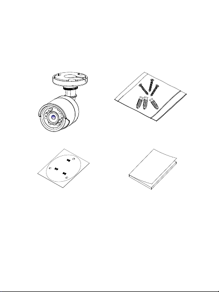
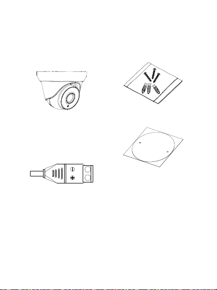
HD-TVI fixed lens bullet camera
Camera with power
and video output cable
harness (cables not
shown)
3 screws (4 ×
25 mm) and 3
anchors (7.5 ×
24.5 mm)
Mounting template
6 Installation Guide
Installation guide
Page 9
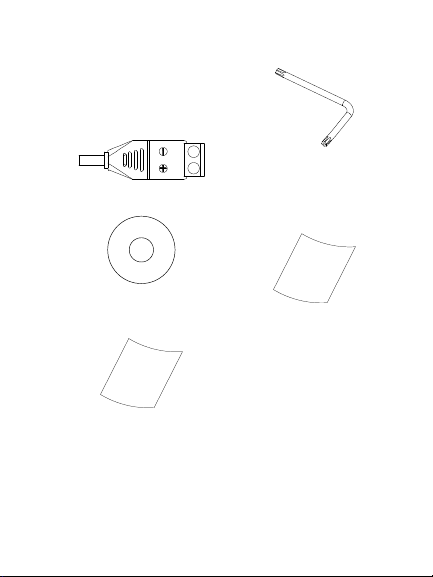
• 12 VDC connector:
Two terminal
connector with
positive and negative
indicators
• CD
• Torx wrench
• Equipment disposal
sheet
• Battery disposal sheet
Installation Guide 7
Page 10
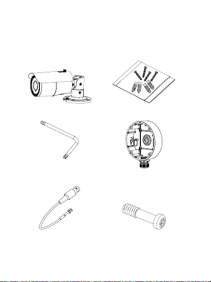
HD-TVI VF motorized lens bullet camera
Camera with power
and video output
cable harness (cables
not shown)
4 screws (4 ×
25 mm) and 4 (7.5 ×
24.5 mm) anchors
• Torx wrench
• Back box
• Video test cable
8 Installation Guide
• 4 screws (M4.8 ×
18). Used with the
back box
Page 11
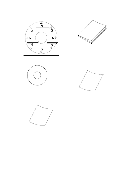
Mounting template
Ceiling Mounting
1
1
1
1
2
2
2
2
1:Screw Hole for
Bracket
2:Screw Hole for
Mounting Base
• CD
Installation guide
• Equipment disposal
sheet
• Battery disposal
sheet
Installation Guide 9
Page 12
HD-TVI fixed lens turret camera
Camera with power
and video output
cable harness (cables
not shown)
• 3 screws (4 × 25 mm)
and 3 anchors (7.5 ×
24.5 mm)
• 12 VDC connector:
Two terminal
connector with
positive and negative
indicators
Mounting template
10 Installation Guide
Page 13
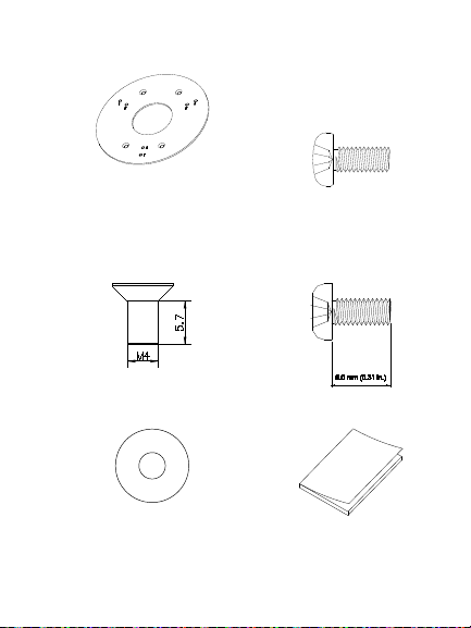
• Adapter plate
4 screws (PM6-32 ×
10). Used to attach the
turret camera to a 2
Gang electrical box
4 screws (KM4 × 8).
Used to attach the
turret camera to the
bracket
3 screws (PM4 x 8).
Used to attach the
turret camera to the
adapter)
• CD
Installation Guide 11
Installation guide
Page 14
Equipment disposal
sheet
Battery disposal sheet
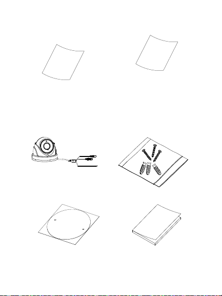
HD-TVI VF motorized lens turret camera
Camera with power
and video output cable
harness
3 screws (4 × 25
mm) and 3 anchors
(7.5 × 24.5 mm)
Template
12 Installation Guide
Installation guide
Page 15
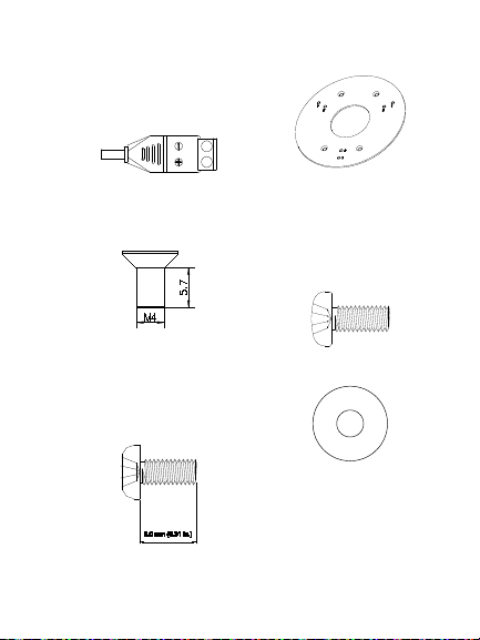
• 12 VDC connector:
Two-terminal
connector with positive
and negative indicators
Adapter plate
4 screws (KM4 x 8).
Used to attach turret
camera to bracket
3 screws (PM4 x 8).
Used to attach the
turret camera to the
adapter)
4 screws (PM6-32
× 10). Used to
attach the turret
camera to a 2 Gang
electrical box
• CD
Installation Guide 13
Page 16

• Equipment disposal
sheet
• Battery disposal
sheet
14 Installation Guide
Page 17
Camera description
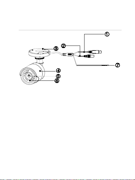
5. Lens
Figure 1: HD-TVI fixed lens bullet camera
1. Selectable TVI or
960H output
2. 12 VDC power
3. Mounting base
4. Camera body
Installation Guide 15
6. IR LEDs
7. HD-TVI (wires
disconnected) /
960H (wires
connected
together) selection
Page 18
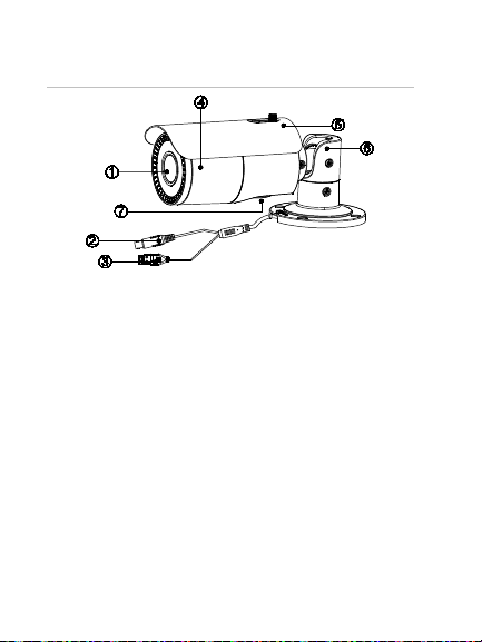
Figure 2: HD-TVI VF motorized lens bullet
4. Camera body
camera
1. Lens
2. Selectable TVI or
960H output
3. 12 VDC/24 VAC
power
Note: When making adjustments to the motorized lens
bullet, it is important to make sure that the access cover for
the area that contains the video test cable connector, OSD
menu button, and the 960H/TVI selection switch is properly
tightened to prevent leakage. The access cover should be
rotated until it is tight, up against the camera body.
16 Installation Guide
5. Sunshield
6. Mounting base
7. Access to 960H or
TVI selection
switch
Page 19

1. Video test cable
2. OSD menu button
Note: When making adjustments to the motorized lens
bullet, it is important to make sure that the access cover for
the area that contains the video test cable connector, OSD
menu button, and the 960H/TVI selection switch is properly
tightened to prevent leakage. The access cover should be
rotated until it is tight, up against the camera body.
Installation Guide 17
3. 960H/TVI
selection switch
Page 20

Figure 3: HD-TVI fixed lens turret camera
together) selection
1. Trim ring
2. Housing
3. Base
4. Lens assembly
5. 12 VDC power
18 Installation Guide
6. Selectable TVI or
960H output
7. HD-TVI (wires
disconnected) /
960H (wires
connected
Page 21

Figure 4: HD-TVI VF motorized lens turret
together) selection
camera
1. Lens assembly
2. Housing
3. Trim ring
4. Base
5. OSD (5-direction)
button
Installation Guide 19
6. 12 VDC power
7. Selectable TVI or
960H output
8. HD-TVI (wires
disconnected) /
960H (wires
connected
Page 22

Mounting the HD-TVI fixed lens bullet camera
Surface mount
1. Place the provided template level against the
mounting surface and mark the position of the
mounting holes.
2. Following all local safety regulations, drill and
prepare the mounting and cable access (if
required) holes.
3. Route the cables through the cable access
hole.
4. Secure the camera to the surface with the
mounting hardware that was provided.
20 Installation Guide
Page 23

Pan position range: 0-360°
P
T
R
range: 360°
0-180°
5. Connect the corresponding cables.
6. Adjust the camera to get the best viewing
angle. See the figure below.
(pan) adjustment
(tilt) adjustment
(rotation) adjustment
Rotation position
Tilt position range:
Installation Guide 21
Page 24

a) Loosen the P screw to adjust the pan
direction [0-360°]. Tighten the screw after
completing the adjustment.
b) Loosen the T screw to adjust the tilt
direction [0-180°]. Tighten the screw after
completing the adjustment.
c) Loosen the R screw and rotate the camera
[0-360°] to adjust the lens to the desired
surveillance angle. Tighten the screw after
completing the adjustment.
7. Tighten the locking screws and the trim ring to
position the camera in place.
Surface mount when using the optional
back box
Note: Fixed lens bullet back box or 2 gang adapter
plate are supplied separately.
1. Remove the cover from the back box and align
the screw holes of the bullet camera with the
holes in the back box cover.
22 Installation Guide
Page 25

2. Route the cables through the cable access hole
of the back box. Mount the camera to the back
box cover using the screws provided.
3. Place the mounting template level against the
mounting surface and mark the position of the
mounting holes. Use the ‘UP’ marking on the
back box and camera mounting base as a
reference.
Installation Guide 23
Page 26

4. Following all local safety regulations, drill and
prepare the mounting holes.
5. Install the back box to the mounting surface
using the hardware provided.
24 Installation Guide
Page 27

6. Connect the corresponding cables and install
the back box cover and camera to the back
box.
7. Refer to step 6 of “Surface mount” on page 20
to adjust the camera viewing angle.
Installation Guide 25
Page 28

Mounting the HD-TVI VF motorized lens bullet camera
Surface mount when using the optional
back box
1. Place the provided template level against the
mounting surface and mark the position of the
mounting holes.
2. Following all local safety regulations, drill and
prepare the mounting and cable access (if
required) holes.
3. Route the cables through the cable access
hole.
26 Installation Guide
Page 29

4. Secure the camera to the mounting surface
with the provided hardware.
5. Connect the corresponding cables.
6. Adjust the camera to get the best viewing
angle. See the figure below.
Installation Guide 27
Page 30

P (pan)
adjustment
T (tilt) adjustment
R (rotation)
adjustment
a) Loosen the P screw to adjust the pan
direction [0-360°]. Tighten the screw after
completing the adjustment.
b) Loosen the T screw to adjust the tilt
direction [0-180°]. Tighten the screw after
completing the adjustment.
c) Loosen the R screw and rotate the camera
[0-360°] to adjust the lens to the desired
surveillance angle. Tighten the screw after
completing the adjustment.
28 Installation Guide
Page 31

Surface mount when using the optional
back box
1. Remove the cover from the back box and align
the screw holes of the bullet camera with the
holes in the back box cover.
2. Route the cables through the cable access hole
of the back box. Install the camera to the back
box cover using the screws provided. See
figure below.
Installation Guide 29
Page 32

3. Place the provided template level against the
mounting surface and mark the position of the
mounting holes.
4. Following all local safety regulations, drill and
prepare the mounting holes.
5. Install the back box to the mounting surface
using the hardware provided.
30 Installation Guide
Page 33

6. Connect the corresponding cables and install
the back box cover with camera to the back
box.
Installation Guide 31
Page 34

7. Refer to step 6 of “Surface mount” on page 28
to adjust the camera to the desired viewing
angle.
Mounting the HD-TVI fixed lens turret camera
Surface mount
1. Disassemble the turret camera by rotating the
trim ring, as shown below.
2. Place the provided template level against the
mounting surface and mark the position of the
mounting holes.
32 Installation Guide
Page 35

3. Following all local safety regulations, drill and
prepare the mounting and cable holes.
4. Route the cables through the cable access (if
required) hole.
5. Secure the mounting base to the mounting
surface with the hardware provided.
Installation Guide 33
Page 36

6. Route the cables. Connect the power cord and
TVI cables.
7. Reassemble the turret camera by rotating the
trim ring back in place.
If installing the turret camera to a wall mount or
other accessory, an adapter plate is provided.
34 Installation Guide
Page 37

Install the adapter plate to the accessory with
three PM4 x 8 screws, referencing number "2".
8. Adjust the camera to get the best viewing
angle. See figure below.
Installation Guide 35
Page 38

Pan position range: 0-360°
Tilt position range:
0-75°
Rotation position
range: 0-360°
a) Hold the camera body and rotate the
enclosure to adjust the pan angle [0- 360°].
b) Move the camera body up and down to
adjust the tilt angle [0-75°].
c) Rotate the camera body to adjust the
azimuth angle [0-360°].
36 Installation Guide
Page 39

Surface mount when using the optional
back box
1. Disassemble the turret camera by rotating the
trim ring, as shown below.
2. Remove the cover from the back box.
3. Place the provided template level against the
mounting surface and mark the position of the
mounting holes.
4. Following all local safety regulations, drill and
prepare the mounting holes.
Installation Guide 37
Page 40

5. Route the cables through the cable access hole
of the back box. Mount the camera to the cover
of the back box.
6. Mount the back box to the mounting surface.
38 Installation Guide
Page 41

7. Connect the corresponding cables and install
the back box cover, with camera, to the back
box.
8. Rotate the trim ring back on to the camera, as
shown below.
Installation Guide 39
Page 42

9. Refer to step 8 of “Surface mount” on page 32
to adjust the camera to the desired viewing
angle.
40 Installation Guide
Page 43

Mounting the HD-TVI VF motorized lens turret camera
Surface mount
1. Place the provided template level against the
mounting surface and mark the position of the
mounting holes.
2. Following all local safety regulations, drill and
prepare the mounting holes.
3. Disassemble the turret camera by rotating the
trim ring counterclockwise, as shown below.
4. Route the cables through the cable access (if
required) hole.
Installation Guide 41
Page 44

5. Secure the mounting base to the surface using
the screws provided.
If installing the turret camera to a wall mount or
other accessory, an adapter plate is provided.
Install the adapter plate to the accessory with
three PM4 x 8 screws, referencing number "2".
42 Installation Guide
Page 45

6. Reassemble the turret camera by rotating the
trim ring back on the camera, as shown below.
Helpful hints when mounting the turret camera:
a) Mount the turret base to a surface.
Installation Guide 43
Page 46

b) When mounting on a wall, aim the lens
towards the floor and the UP marking on
the camera assembly towards the ceiling.
c) Place the camera eyeball assembly on two
of the three standoffs of the mounting
base.
d) Place the turret housing over the camera
assembly.
e) Place the metal ring over the camera turret
housing.
f) Hold the turret housing and camera
assembly in place with your right hand.
g) Using your left hand, rotate the metal ring
clockwise to tighten it.
h) Prior to completely tightening the ring, aim
the camera body/lens towards the desired
position.
7. Adjust the camera to get the best viewing angle
(see figures below).
44 Installation Guide
Page 47

a) Hold the camera body and rotate the
Pan position range:
Tilt position range:
Rotation position range: 0-360°
enclosure to adjust the pan angle [0- 360°].
b) Move the camera body up and down to
adjust the tilt angle [0-75°].
c) Rotate the camera body to adjust the
azimuth angle [0-360°].
0-360°
Surface mount when using the optional
back box
1. Remove the cover from the back box.
Installation Guide 45
0-75°
Page 48

2. Place the provided template level against the
mounting surface and mark the position of the
mounting holes.
3. Following all local safety regulations, drill and
prepare the mounting holes.
4. Disassemble the turret camera by rotating the
trim ring counterclockwise, as shown below.
46 Installation Guide
Page 49

5. Route the cables through the cable access hole
of the back box. Mount the camera to the back
box.
Installation Guide 47
Page 50

6. Install the back box to the mounting surface
using the hardware provided.
7. Connect the corresponding cables and install
the back box cover and camera to the back
box.
48 Installation Guide
Page 51

8. Rotate the trim ring back on to the camera
body, as shown by the arrow.
9. Adjust the camera according to step 8 of
“Surface mount” on page 37 to get the best
viewing angle.
Installation Guide 49
Page 52

Specifications
Power supply
12 VDC / 24 VAC
Current
Power
consumption
TVB-2407/TVB-4407:
TVB-2407 / TVB-4407:
50 Installation Guide
12 VDC: Max. 417 mA
TVB-2408/TVB-4408:
12 VDC: Max. 750 mA / 24 VAC:
Max. 400 mA
TVT-2401/TVT-4401:
12 VDC: Max. 417 mA
TVT-2402/TVT-4402:
12 VDC: Max. 550 mA
12 VDC: Max. 5 W
TVB-2408/TVB-4408:
12 VDC: Max. 9 W / 24 VAC:
12 W
TVT-2401/TVT-4401:
12 VDC: Max. 5 W
TVT-2402/TVT-4402:
12 VDC: Max. 6 W
Page 53

Weight (net)
Dimensions
TVB-2407/TVB-4407:
Installation Guide 51
TVB-2407/TVB-4407:
370 g / 0.82 lb.
TVB-2408/TVB-4408:
900 g / 1.98 lb.
TVT-2401/TVT-4401:
350 g / 0.77 lb.
TVT-2402/TVT-4402:
750 g / 1.57 lb.
58.2 × 154.5 mm / 2.3 × 6.08 in.
TVB-2408/TVB-4408:
94.7 × 265.4 mm / 3.7 × 10.45 in.
TVT-2401/TVT-4401:
226.7 × 97.84 mm / 5 × 3.85 in.
TVT-2402/TVT-4402:
135.78 × 118.2 mm / 5.35 × 4.65
in.
Page 54

Legal and regulatory
information
Class A: This equipment has been tested and found to comply with
erated in a commercial environment. This equipment generates,
uses, and can radiate radio frequency energy and, if not installed
Copyright:
© 2017 United Technologies Corporation. All rights reserved.
Interlogix is part of UTC Climate, Controls & Security, a unit of
United Technologies Corporation.
Trademarks and patents:
Trade names used in this document may be trademarks or
registered trademarks of the manufacturers or vendors of the
respective products.
Manufacturer:
Interlogix
2955 Red Hill Avenue, Costa Mesa, CA 92626-5923, USA
Authorized EU manufacturing representative:
UTC Fire & Security B.V.
Kelvinstraat 7, 6003 DH Weert, The Netherlands
Certifica tion:
FCC compliance: Class A
the limits for a Class A digital device, pursuant to part 15 of the
FCC Rules. These limits are designed to provide reasonable
protection against harmful interference when the equipment is
op
52 Installation Guide
Page 55

and used in accordance with the instruction manual, may cause
harmful interference to radio communications. Operation of this
equipment in a residential area is likely to cause harmful
interference in which case the user will be required to correct the
interference at his own expense.
FCC conditions:
This device complies with Part 15 of the FCC Rules. Operation is
subject to the following two conditions:
(1) This device may not cause harmful interference.
(2) This Device must accept any interference received, including
interference that may cause undesired operation.
ACMA compliance:
Notice! This is a Class A product. In a domestic environment this
product may cause radio interference in which case the user may
be required to take adequate measures.
Canada:
This Class A digital apparatus complies with CAN ICES-003
(A)/NMB-3 (A).
Cet appareil numérique de la classe A est conforme à la norme
CAN ICES-003 (A)/NMB-3 (A).
European Union directives:
This product and - if applicable - the supplied accessories too are
marked with "CE" and comply therefore with the applicable
harmonized European standards listed under the EMC Directive
2014/30/EU, the RoHS Directive 2011/65/EU.
Installation Guide 53
Page 56

2012/19/EU (WEEE directi ve): Products marked
with this symbol cannot be disposed of as
unsorted municipal waste in the European
Union. For proper recycling, return this
product to your local supplier upon the
purchase of equivalent new equipment, or
dispose of it at designated collection points.
For more information see:
www.recyclethis.info.
Contact information:
For contact information, see www.interlogix.com or
www.utcfssecurityproducts.eu
54 Installation Guide
Page 57

Page 58

Page 59

Page 60

 Loading...