

Interlogix TVR 60 series, TruVision DVR 60, TVR-6016-500, TVR-6016-1T, TVR-6016-2T User Manual
...Page 1

TruVision DVR 60 User
Manual
P/N 1069895F-EN • REV 6.0 • ISS 10MAY11
Page 2

Copyright
© 2011 UTC Fire & Security. All rights reserved.
Trademarks and patents
Interlogix, TruVision and logos are trademarks of UTC Fire & Security.
Other trade names used in this document may be trademarks or registered
trademarks of the manufacturers or vendors of the respective products.
Manufacture
r
UTC Fire & Security Americas Corporation, Inc.
2955 Red Hill Avenue, Costa Mesa, CA 92626-5923, USA
Authorized EU manufacturing representative:
UTC Fire & Security B.V.
Kelvinstraat 7, 6003 DH Weert, The Netherlands
Certification
FCC compliance
Class A: This equipment has been tested and found to comply with the limits for
a Class A digital device, pursuant to part 15 of the FCC Rules. These limits are
designed to provide reasonable protection against harmful interference when the
equipment is operated in a commercial environment. This equipment generates,
uses, and can radiate radio frequency energy and, if not installed and used in
accordance with the instruction manual, may cause harmful interference to radio
communications. Operation of this equipment in a residential area is likely to
cause harmful interference in which case the user will be required to correct the
interference at his own expense.
ACMA compliance
Notice! This is a Class A product. In a domestic environment this product may
cause radio interference in which case the user may be required to take
adequate measures.
Canada
This Class A digital apparatus complies with Canadian ICES-003.
Cet appareil numérique de la classe A est conforme à la norme NMB-0330 du
Canada.
European Union directives
12004/108/EC (EMC directive): Hereby, UTC Fire & Security declares that this
device is in compliance with the essential requirements and other relevant
provisions of Directive 2004/108/EC.
2002/96/EC (WEEE directive): Products marked with this symbol cannot be
disposed of as unsorted municipal waste in the European Union. For proper
recycling, return this product to your local supplier upon the purchase of
equivalent new equipment, or dispose of it at designated collection points. For
more information see: www.recyclethis.info.
2006/66/EC (battery directive): This product contains a battery that cannot be
disposed of as unsorted municipal waste in the European Union. See the product
documentation for specific battery information. The battery is marked with this
symbol, which may include lettering to indicate cadmium (Cd), lead (Pb), or
mercury (Hg). For proper recycling, return the battery to your supplier or to a
designated collection point. For more information see: www.recyclethis.info.
Contact information
www.interlogix.com
www.utcfssecurityproducts.eu
Customer support
www.interlogix.com/customer-support
Page 3

TruVision DVR 60 User Manual i
Content
Chapter 1 Product introduction 1
Product overview 1
Features 2
Chapter 2 Installation 5
Installation environment 5
Unpacking the TVR 60 and its accessories 5
HDD capacity 6
Connecting devices to the rear panel 6
IP cameras supported 7
PTZ dome camera set up 8
Wiring the keypad 12
RS-485 ports 14
RS-232 port 15
Monitor connections 15
Loop through 15
Audio inputs and output 15
Brackets 16
Chapter 3 Getting started 19
Turning on and off the DVR 19
Using the Setup Wizard 19
Chapter 4 Operating instructions 23
Controlling the TVR 60 23
Using the front panel 23
Using the mouse 25
Using the IR remote control 26
Main menu overview 29
Chapter 5 Live mode 33
Description of live mode 33
Digital zoom 33
Switching monitors 34
Pop-up menus for mouse operation 35
Viewing in full screen 36
Viewing in multiscreen 36
Sequencing cameras in live mode 37
Cameo shortcuts 37
Chapter 6 Configuring the live mode display 39
Configuring monitor and DVR options 39
Configuring time and date 41
Page 4

ii TruVision DVR 60 User Manual
Configuring display options 42
Chapter 7 Controlling a PTZ dome camera 47
Configuring PTZ settings 47
Pop-up menu for mouse operation 49
Setting presets, preset tours and shadow tours 49
Chapter 8 Playing back a recording 55
The playback control panel 56
Playing back recorded video 56
Exiting playback mode 63
Chapter 9 Archiving recorded files 65
Archiving files 65
Archiving video clips 68
Managing backup devices 68
Playing back archived files on a PC 69
Chapter 10 Using the Web browser 71
Windows Vista and 7 users 71
Accessing the Web browser 72
Web browser overview 72
Using the Web browser to configure the device 74
Searching and playing back recorded video 75
Searching for event logs 77
Live dual streaming 77
Controlling a PTZ dome camera in the Web browser 77
Chapter 11 Configuring recording settings 79
Initializing recording settings 79
Defining a recording schedule 81
Protecting recorded files 83
Configuring advanced HDD settings 84
Chapter 12 Configuring alarm settings 87
Motion detection 87
Setting up external alarms 92
Triggering alarm outputs manually 94
Setting up system notifications 95
Detecting video loss 96
Detecting video tampering 97
Chapter 13 Configuring network settings 99
Configuring basic network settings 99
Configuring the DDNS 100
Configuring an NTP server 101
Configuring a remote alarm host 101
Configuring multicast 102
Page 5

TruVision DVR 60 User Manual iii
Configuring the server and HTTP Ports 102
Configuring e-mail settings 103
Chapter 14 Camera management 105
Enabling or disabling analog cameras 106
Configuring IP cameras 107
Configuring the OSD settings 108
Setting up privacy masking 109
Adjusting video image settings 110
Chapter 15 HDD management 113
Initializing HDDs 113
Setting HDD groups 113
Setting the HDD status 114
Checking HDD status 116
Configuring HDD alarms 117
Chapter 16 Configuring the DVR settings 119
Changing the language 119
Managing users 119
Updating system firmware 125
Restoring default settings 127
Viewing system information 127
Viewing system logs 127
Appendix A Troubleshooting 129
Appendix B Specifications 131
Appendix C PTZ protocols 135
Appendix D TVK-505U keypad 137
Using a TVK-505U keypad 137
Appendix E KTD-405 keypad 139
Supported firmware 139
Wiring the keypad 139
Setting up the keypad to work with the TVR 60 140
Operating the keypad 142
Appendix F Camera matrix 149
Appendix G Glossary 153
Index 155
Menu map 158
Page 6

iv TruVision DVR 60 User Manual
Page 7

TruVision DVR 60 User Manual 1
Chapter 1
Product introduction
Product overview
This is the TruVision DVR 60 User Manual for models:
Table 1: Product codes
Product code EMEA Americas
TVR-6016-500 Available Unavailable
TVR-6016-1T Available Unavailable
TVR-6016-2T Available Available
TVR-6016-4T Available Available
TVR-6016-8T Available Available
TVR-6016-12T Available Available
Note: Some model versions are not available across all regions. EMEA product
codes end with “EA” and are shipped with UK and European power cords.
The TruVision™ DVR 60 (TVR 60) is a full featured and scalable hybrid digital
video recording system with the ability to store, display live, search, and transmit
video from up to 24 analog or IP cameras.
Its dual streaming functionality allows the user to set up different settings for
recording and streaming video in live mode.
TruVision DVR 60 can fully integrate with the license-free TruVision Navigator
software, which is ideal for the most commercial applications. TVR 60’s easy and
intuitive-to-use web browser interface enables remote configuration and secure
viewing, searching, and playing back of video from computers connected via the
Internet.
Page 8

0BChapter 1: Product introduction
2 TruVision DVR 60 User Manual
Features
This section describes the available TVR 60 features.
Compression
The TVR 60 supports the following video features:
• Scalable state-of-the-art hybrid H.264 video compression algorithm
• Supports both analog and IP cameras
• Real-time recording of 24 channels at 4CIF resolution
• Supports watermarking.
Storage
The TVR 60 supports the following storage features:
• Supports up to 12TB of onboard storage
• Supports configurable redundant recording
• Supports HDD designed for 24 × 7 operation and high write duty cycles
• Camera to HDD assignment for HDD data grouping
Recording and playback:
The TVR 60 supports the following video features:
• Real-time recording of 24 channels at 4CIF resolution
• Supported IP devices: TruVision H.264 MPX and SD IP cameras, UltraView
Encoder 10, UltraView IP, CamPlus2 IP and Panasonic IP cameras
• Dual streaming functionality allows the use of different settings for recording
and streaming video
• PTZ and dome camera control via mouse, front panel joystick and IR remote
controller
• E-mail notification upon alarm with attached images and health notifications
Network
The TVR 60 supports the following video features:
• Networkable via Ethernet (TCP/IP) for remote monitoring, searching,
playback, archiving, configuration, alarm notifications and firmware upgrades
• Ability to fully integrate with the license-free TruVision Navigator software and
TVRmobile software.
• Built-in Web server
Other:
The TVR 60 supports the following additional features:
Page 9

0BChapter 1: Product introduction
TruVision DVR 60 User Manual 3
• Auto-detect video (PAL or NTSC) on startup
• Multiple control inputs: front panel, mouse, IR remote control, and keyboard
• Supports KTD-405 / TVK-505U keypad control
• Multi-language support
• Triple monitor support - Monitor A, monitor B and spot monitors
Page 10

0BChapter 1: Product introduction
4 TruVision DVR 60 User Manual
Page 11

TruVision DVR 60 User Manual 5
Chapter 2
Installation
Installation environment
When installing your product, consider these factors:
• Ventilation
• Temperature
• Moisture
• Chassis load
Ventilation: Do not block any ventilation openings. Install in accordance with the
manufacturer’s instructions. Ensure that the location planned for the installation
of the unit is well ventilated.
Temperature: Consider the unit’s operating temperature (0 to 40°C, 32 to 104°F)
and noncondensing humidity specifications (10 to 90%) before choosing an
installation location. Extremes of heat or cold beyond the specified operating
temperature limits may reduce the life expectancy of the TruVision DVR 60. Do
not install the unit on top of other hot equipment. Leave 44 mm (1.75 in.) of
space between rack-mounted TruVision DVR 60 units.
Moisture: Do not use the unit near water. Moisture can damage the internal
components. To reduce the risk of fire or electric shock, do not expose this unit to
rain or moisture.
Chassis: Equipment weighing less than 15.9 kg (35 lb.) may be placed on top of
the unit.
Unpacking the TVR 60 and its accessories
When you receive the product, check the package and contents for damage, and
verify that all items are included. There is an item list included in the package. If
any of the items are damaged or missing, please contact your local supplier.
Items shipped with the product include:
Page 12

1BChapter 2: Installation
6 TruVision DVR 60 User Manual
• IR (infrared) remote control
• Two AAA batteries for the remote control
• AC power cords (US, Europe, UK)
• USB mouse
• DVR
• Video loop through cable
• TruVision DVR 60 Quick Start Guide
• TruVision DVR 60 User Manual (on CD)
HDD capacity
Storage capacity for the TVR 60 varies depending on the model. Refer to Table 2
below for more information.
Table 2: TruVision DVR 60 model types
Model number Description
TVR-6016-500EA TruVision DVR Model 60, 16 ch, 500 GB
TVR-6016-1TEA TruVision DVR Model 60, 16 ch, 1 TB
TVR-6016-2T(EA) TruVision DVR Model 60, 16 ch, 2 TB
TVR-6016-4T(EA) TruVision DVR Model 60, 16 ch, 4 TB
TVR-6016-8T(EA) TruVision DVR Model 60, 16 ch, 8 TB
TVR-6016-12T(EA) TruVision DVR Model 60, 16 ch, 12 TB
Connecting devices to the rear panel
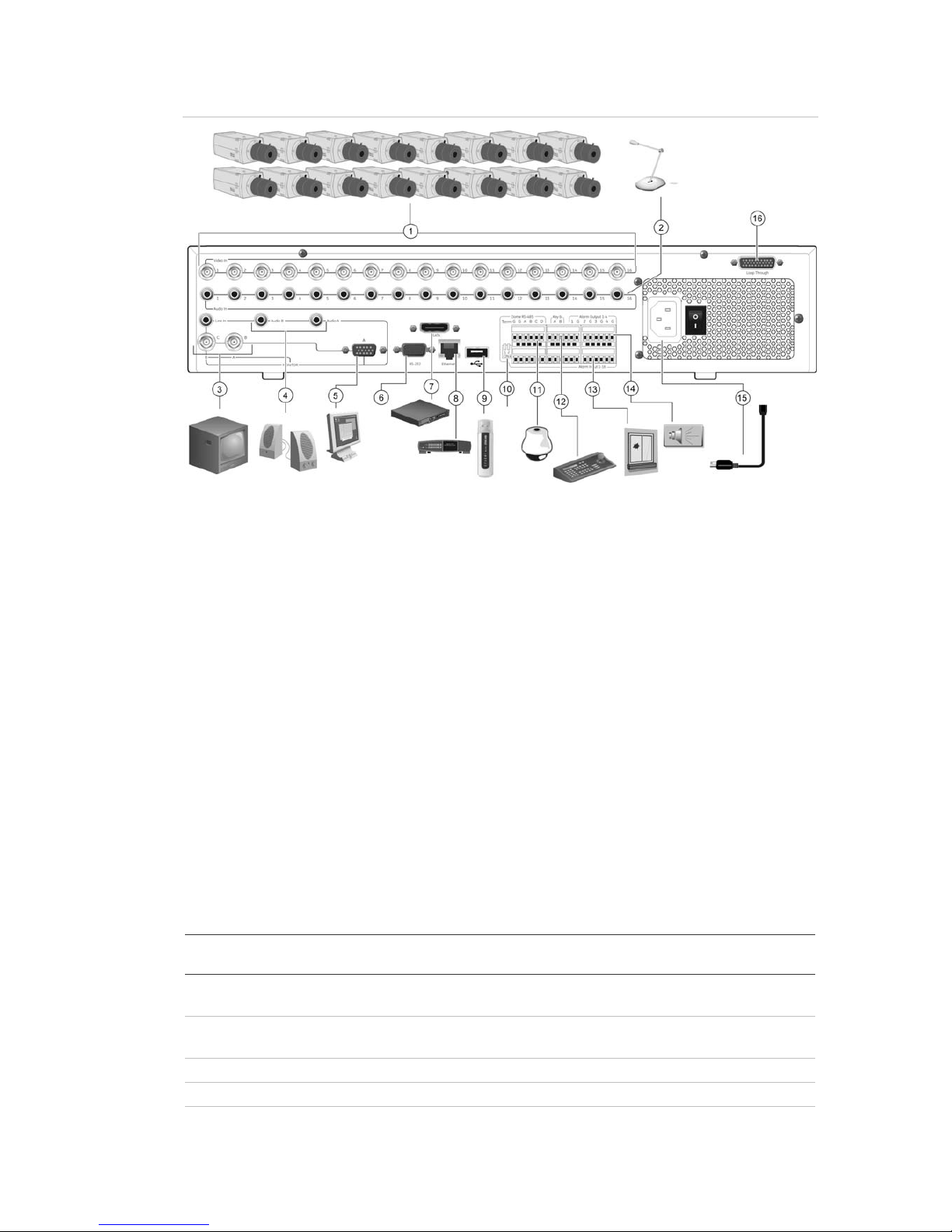
Figure 1 below shows the rear panel connections and describes each connector
on a typical TVR 60 digital video recorder. Details may vary for specific models.
Before powering up the DVR, connect the cameras and a main monitor for basic
operation.
Page 13
1BChapter 2: Installation
TruVision DVR 60 User Manual 7
Figure 1: Rear panel connections
1. Connect up to 16 analog cameras to BNC connectors.
2. Connect to audio inputs (available for each camera) to
RCA connectors.
3. Connect up to two CCTV monitors (monitors B and
C).
4. Connect to speakers for audio output.
5. Connect VGA monitor (default main monitor).
6. For future use.
7. Connect to an eSATA device.
8. Connect to a network.
9. Connect to USB devices such as a mouse. USB
CD/DVD burner and USB HDD are not supported.
10. Terminate the line to the dome cameras using this
RS-485 switch. Default is Off.
11. Connect to a PTZ control.
12. Connect to a keypad (KTD-405 shown)
13. Connect up to 16 alarm input cables to relay outputs.
14. Connect up to four NO/NC alarm relay outputs.
15. Connect to a power cord.
16. Loop through for up to 16 analog cameras (see
item 1).
IP cameras supported
The TVR 60 supports the following IP cameras with their resolutions and
maximum bit rates. See Table 3 below.
Table 3: IP cameras supported
Supported cameras Resolutions
supported
Maximum bit rate Main stream
Maximum bit rate
- Sub stream
TruVision 2MPX camera UXGA, HD720P, 4CIF,
2CIF, CIF, QCIF
2Mbps 1Mbps
TruVision 1.3MPX camera HD720P, 4CIF, 2CIF,
CIF, QCIF
2Mbps 1Mbps
UltraView encoder 4CIF, 2CIF, CIF, QCIF 1.7Mbps 1Mbps
UltraView IP box camera 4CIF, 2CIF, CIF, QCIF 1.7Mbps 1Mbps
UltraView IP dome camera 4CIF, 2CIF, CIF, QCIF 1.7Mbps 1Mbps
Page 14

1BChapter 2: Installation
8 TruVision DVR 60 User Manual
Supported cameras Resolutions
supported
Maximum bit rate Main stream
Maximum bit rate
- Sub stream
UltraView IP PTZ camera 4CIF, 2CIF, CIF, QCIF 1.7Mbps 1Mbps
CamPlus2 IP camera VGA, QVGA 2Mbps N/A
Panasonic IP camera VGA, QVGA 2Mbps N/A
PTZ dome camera set up
Use the USB mouse provided or the optional keypad for local telemetry control. If
using the TVR 60 over a network, use the web browser to control the PTZ dome
cameras or TruVision Navigator.
See Appendix C “PTZ protocols” on page 135 for the supported protocols.
Each PTZ camera must be set up individually. For information on configuring
PTZ dome camera settings, see Chapter 7 “Controlling a PTZ dome camera” on
page 47.
Connecting a TVR 60 to a PTZ dome camera and a
keypad
Use the input/output box that is supplied with the keypad to connect a keypad to
the TVR 60. The keypad can be connected to a PTZ camera for local control or
for control over the network.
See Figure 2 on page 9 for the preferred setup. Any PTZ dome camera can be
controlled as the DVR is doing the PTZ protocol translation. However, this setup
provides only limited dome configuration.
Page 15
1BChapter 2: Installation
TruVision DVR 60 User Manual 9
Figure 2: Connecting a keypad to the TVR 60 for control of a PTZ dome camera over the
network
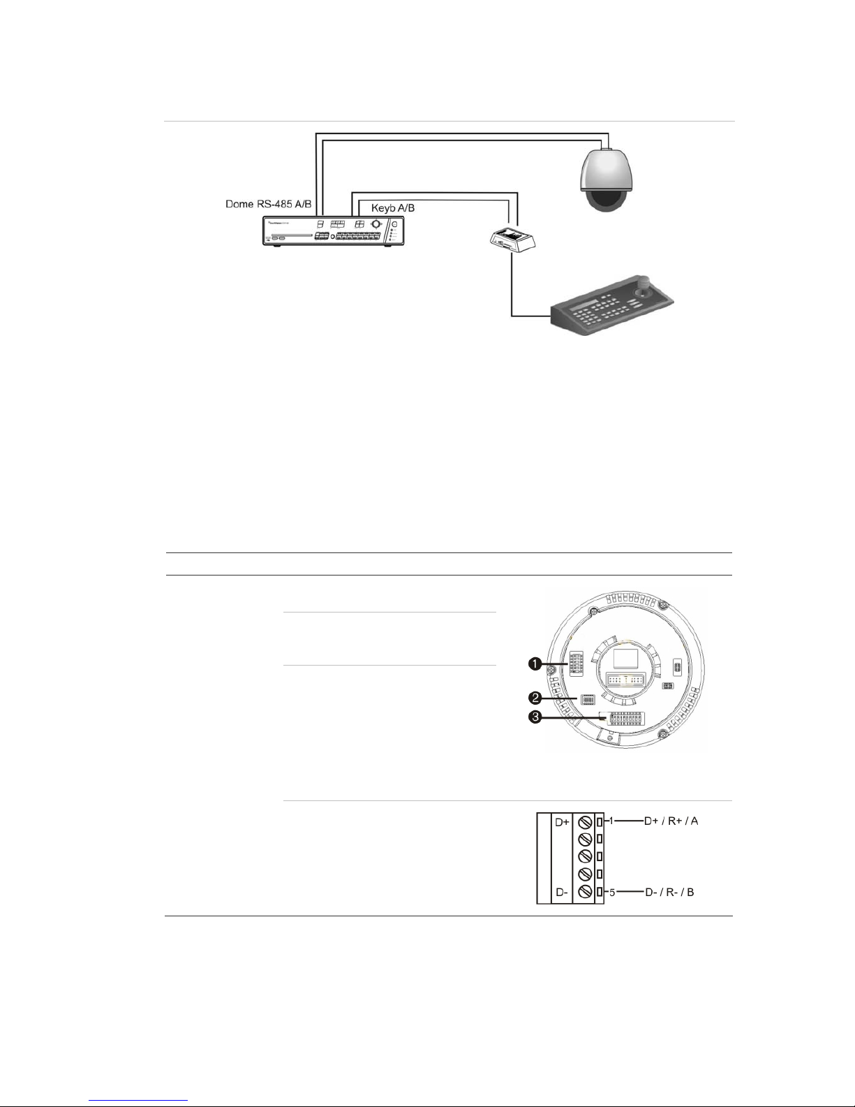
Configuring the PTZ protocols for Interlogix cameras
Before the PTZ dome cameras are assembled in their housings, set their
protocol and address DIP switches for the TVR 60. See Table 4 below for
different Interlogix PTZ dome camera settings.
If you are using PTZ dome cameras from another company, please refer to their
configuration instructions.
Table 4: PTZ protocols for Interlogix cameras
Camera Switch setting
TruVision Mini PTZ
12X: Indoor Dome
Protocol DIP switches: 000000
RS-485
communication DIP
switches:
0000000000
Camera ID DIP
switches:
Select the
camera ID
DIP switch
address as
required
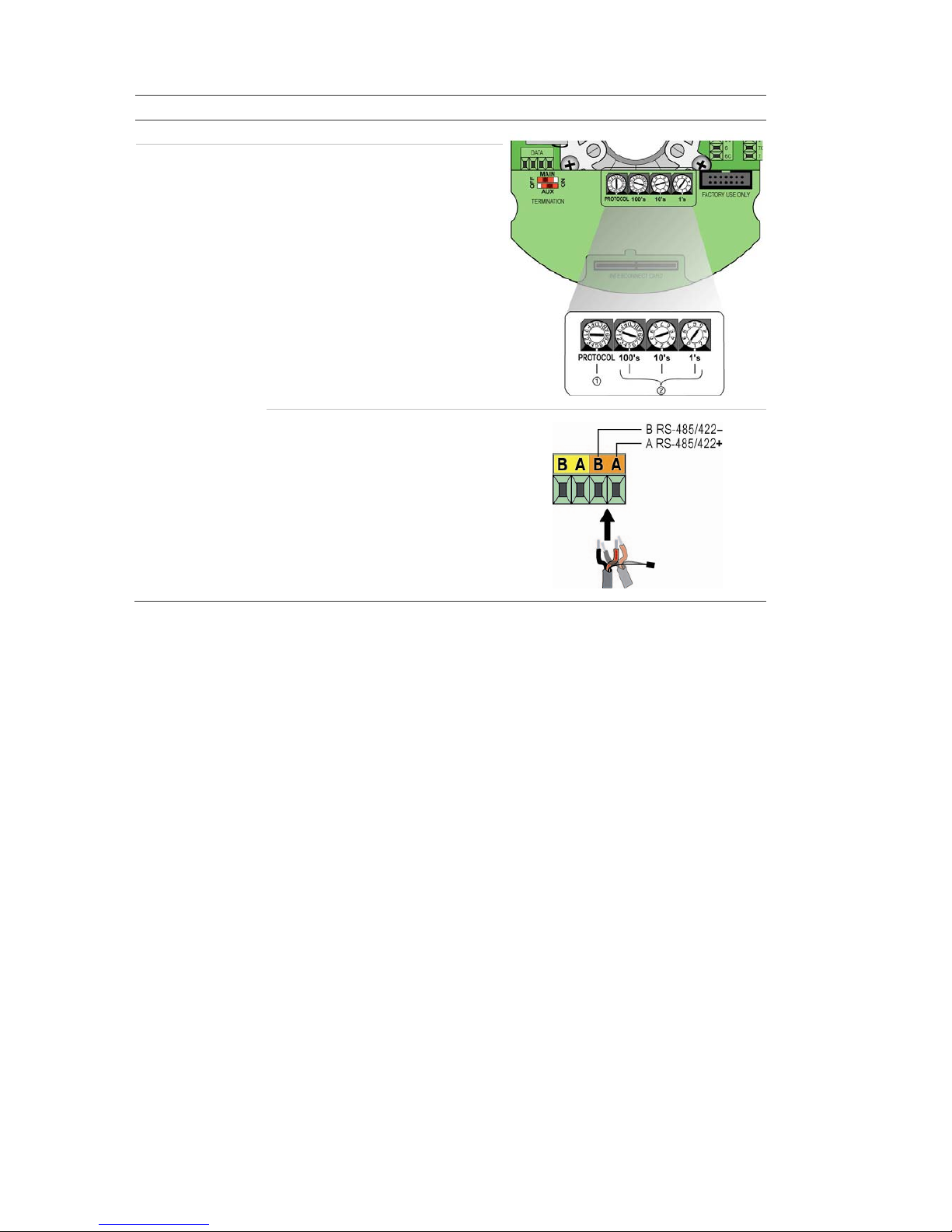
1. Protocol DIP switches
2. RS-485 communication DIP switches
3. Camera ID DIP switches
RS-485 data connector:
Page 16
1BChapter 2: Installation
10 TruVision DVR 60 User Manual
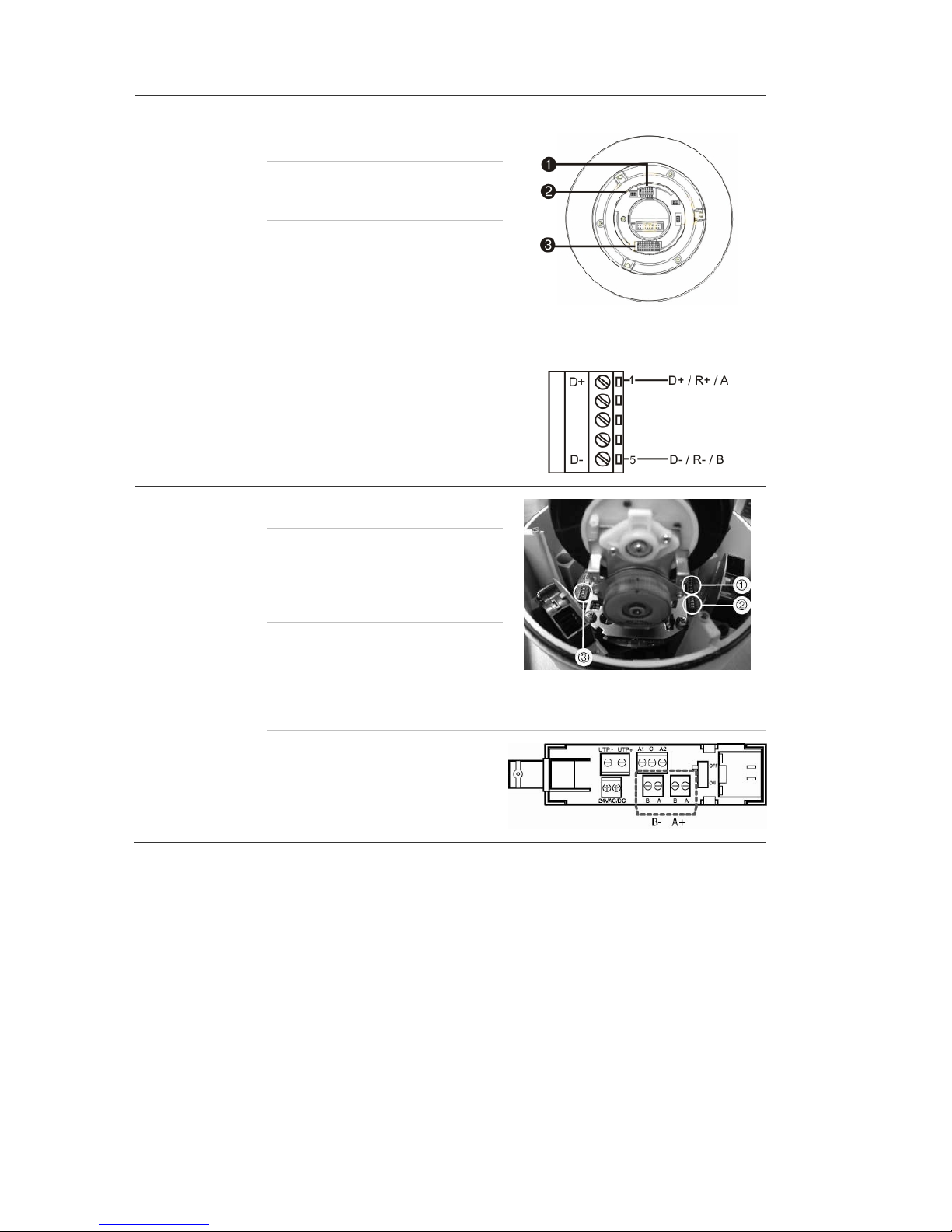
Camera Switch setting
TruVision Mini PTZ
12X: Outdoor Dome
Protocol DIP switches: 000000
RS-485
communication DIP
switches:
0000000000
Camera ID DIP
switches:
Select the
camera ID
DIP switch
address as
required.
1. Protocol DIP switches
2. RS-485 communication DIP switches
3. Camera ID DIP switches
RS-485 data connector:
TruVision Dome 16X
PTZ
Protocol switches: 0111
Address switches: Select the
camera ID
DIP switch
address as
required.
Baud rate: 0000
1. Address switches; 2. Baud switches;
3. Protocol switches
RS-485 data connector:
Page 17
1BChapter 2: Installation
TruVision DVR 60 User Manual 11
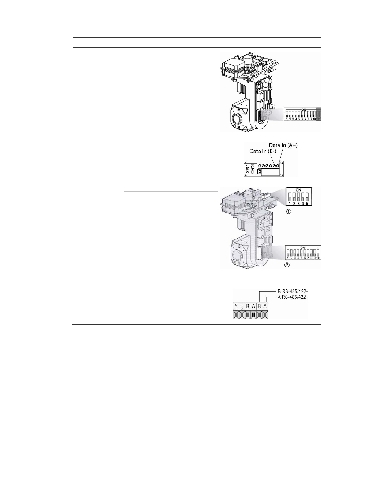
Camera Switch setting
CyberDome Protocol switches: NA
Address switches: Select the
camera ID
DIP switch
address as
required.
RS-485 data connector:
UltraView PTZ Protocol switches: 01000
Address switches: Select the
address
switch
address as
required.
1. Protocol switches; 2. Address switches
RS-485 data connector:
Page 18
1BChapter 2: Installation
12 TruVision DVR 60 User Manual
Camera Switch setting
Legend Protocol switches: 1
Address switches: Select the
camera ID
DIP switch
address as
required.
RS-485 data connector:
Wiring the keypad
The keypad uses RS-485 simplex wiring. The signal is transferred by a single
twisted pair line. A shielded STP CAT5 network cable is recommended. Ground
one end of the cable, either the first or last device on the RS-485 line.
The maximum number of devices that can be installed in one bus is 255, with a
maximum cable length of 1200 m. The cable length can be expanded using a
signal distributor.
Both the first and the last device in series should be terminated with 120 Ohm
resistance to minimize line reflections. See Figure 3 on page 13.
Page 19
1BChapter 2: Installation
TruVision DVR 60 User Manual 13
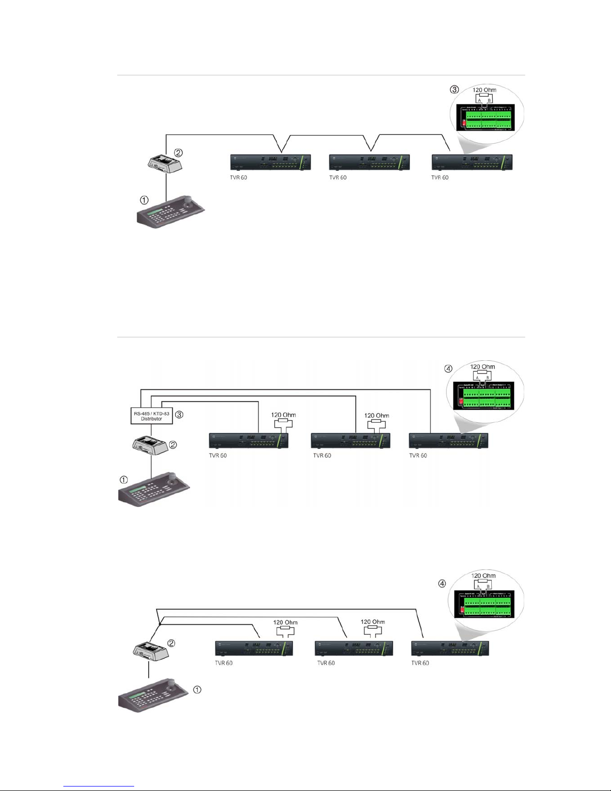
Figure 3: RS-485 bus serial wiring (KTD-405 keypad shown)
1. Keypad
2. I/O box
3. See section “RS-485 ports” on page 14
Use an RS-485 signal distributor for a star wiring configuration. See Figure 4
below.
Figure 4: Star wiring with RS-485 signal distributor
Correct
1. Keypad
2. I/O box
3. RS-485/KTD-83 distributor
4. See section “RS-485 ports” on page 14
Incorrec
t
Page 20
1BChapter 2: Installation
14 TruVision DVR 60 User Manual
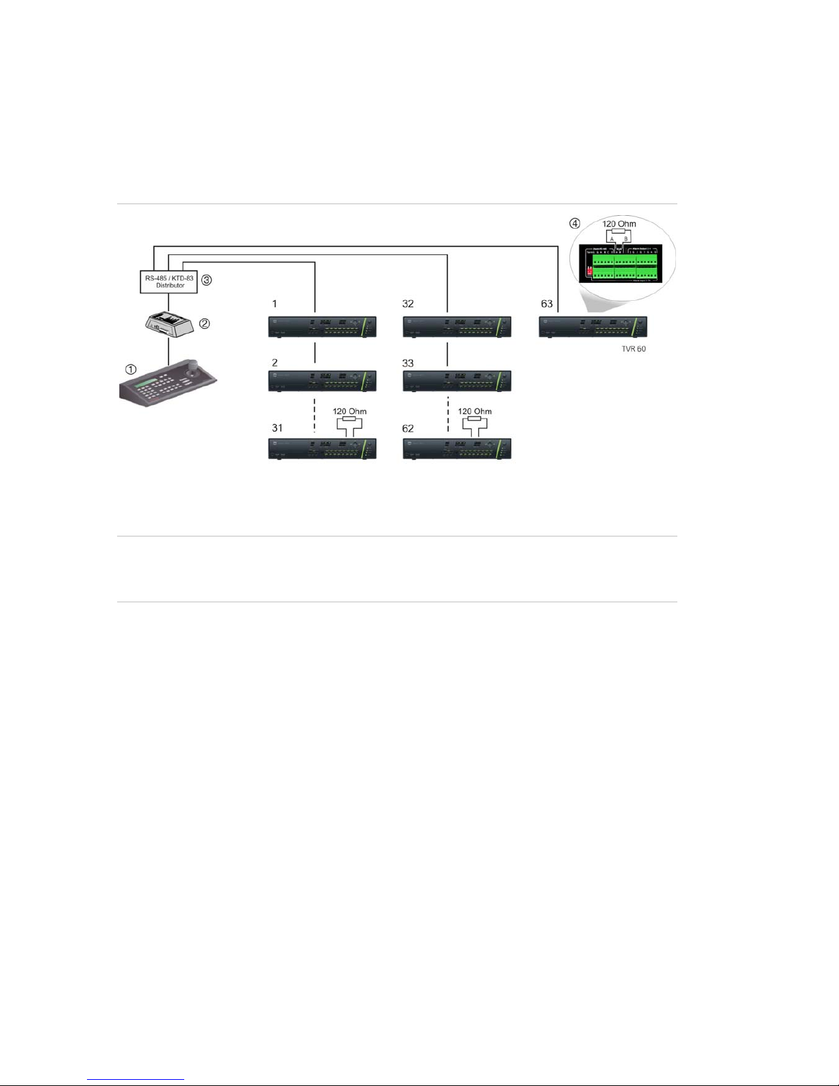
Use an RS-485/KTD-83 signal distributor to increase the maximum number of
devices on the bus as well as the total range. Each distributor output provides
another RS-485 bus, extending the output an additional 1200 m. Up to 31
TVR 60s can be connected to each output. See Figure 5 below.
Figure 5: Expanding the system with an RS-485 signal distributor
1. Keypad
2. I/O box
3. RS-485/KTD-83 distributor
4. See section “RS-485 ports” below
Caution: Most signal distributors are unidirectional. This means that the signal
only flows from the input towards the outputs. Consequently it is not possible to
connect several keypads.
See section “RS-485 ports” below to configure the RS-485 port communication
settings.
RS-485 ports
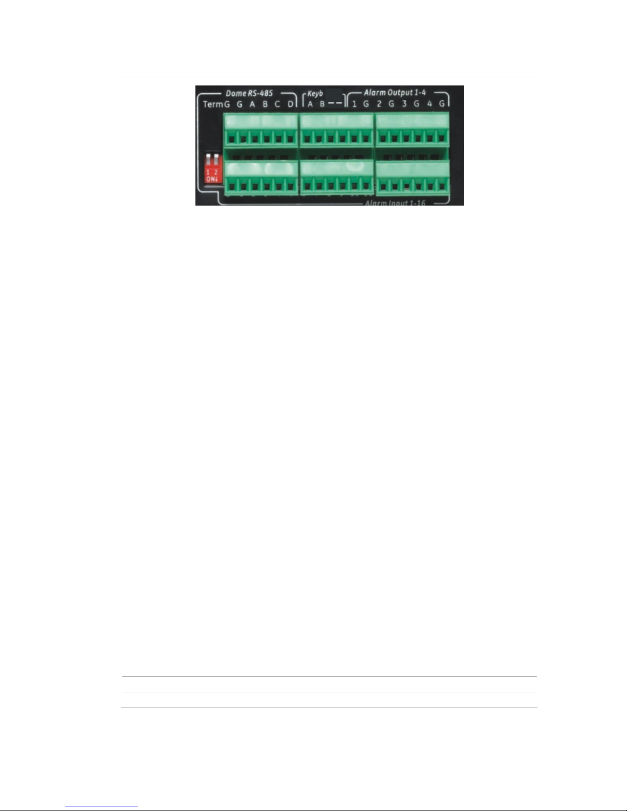
There are two RS-485 ports on the rear panel of the TVR 60. See Figure 6 on
page 15 for the serial pin outs.
• Dome RS-485:
Term G: Termination of RS-485 bus
G: Ground
A and B: Connect pan, tilt, zoom control of PTZ dome cameras. A = +, B = -
C and D: Not used
• Keyb: Connect the keypad.
Page 21
1BChapter 2: Installation
TruVision DVR 60 User Manual 15
Figure 6: RS-485 pins
RS-232 port
The RS-232 port will be available for future use to connect CBR-PB3-POS (pointof-sale) and ATM devices to the TVR 60.
Monitor connections
Connect the unit to the monitors via 75-ohm video coaxial cables with BNC
connectors. The unit provides a 1 Vpp CVBS signal. See Figure 1 on page 7 for
connecting a monitor to a TVR 60.
The TVR 60 supports up to 1280 × 1024 / 60 Hz resolution in VGA. The monitor
resolution should be at least 800 × 600. Adjust your monitor accordingly to this
resolution.
Loop through
You can loop through the analog cameras to equipment such as a matrix,
monitors or a second DVR. There are 16 numbered loop-through BNC outputs.
See Figure 1 on page 7.
Audio inputs and output
The unit is equipped with 16 audio inputs and two audio outputs. Both the audio
output and the audio inputs are line-level. Each 16 audio input is associated with
one of the 16 cameras.
Audio input RCA jack, 315 mV, 40k Ohms. Unbalanced
Audio output RCA jack, 315mV, 600 Ohms. Unbalanced
Note: Line-level audio requires amplification.
Page 22
1BChapter 2: Installation
16 TruVision DVR 60 User Manual
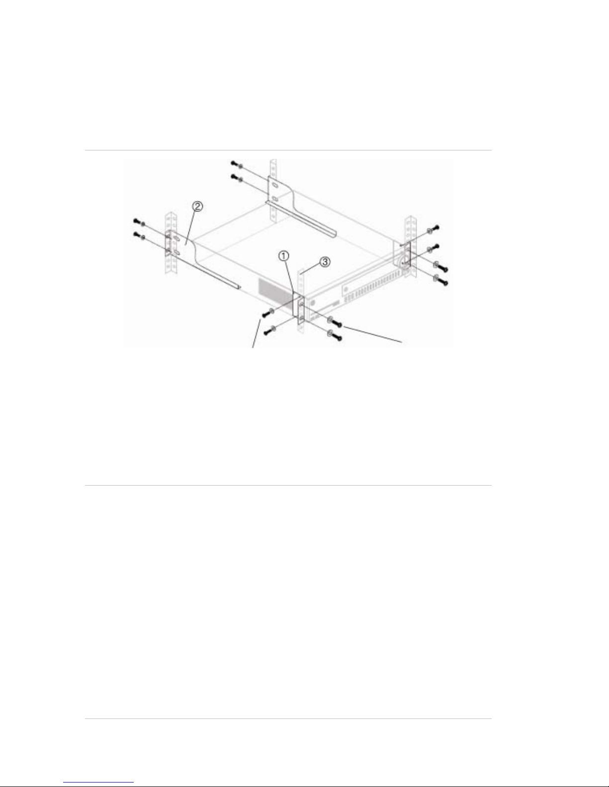
Brackets
The DVR is easily rack-mountable with the purchase of the TVR-RK-1 rackmount kit. See Figure 7 below. Contact your local supplier to order it.
Figure 7: Rack mount installation
Attach small front rack ears to the unit
(screws supplied)
Attach DVR to front rails
(screws not included)
To install the racks:
1. Attach the two small front-rack mount ears to the DVR (screws supplied).
2. Attach the two large rear support brackets (not supplied) to the rear rails.
3. Attach the DVR to the front rails (screws not supplied).
Caution:
Do not rack mount the TVR 60 without the rear rails installed. Failure to install the rear
rails can damage the DVR.
Elevated Operating Ambient - If installed in a closed or multi-unit rack assembly,
the operating ambient temperature of the rack environment may be greater than
room ambient. Therefore, consideration should be given to installing the
equipment in an environment compatible with the maximum ambient
temperature (40°C) specified by the manufacturer.
Reduced Air Flow - Installation of the equipment in a rack should be such that the
amount of air flow required for safe operation of the equipment is not
compromised.
Mechanical Loading - Mounting of the equipment in the rack should be such that
a hazardous condition is not achieved due to uneven mechanical loading.
Page 23

1BChapter 2: Installation
TruVision DVR 60 User Manual 17
Circuit Overloading - Consideration should be given to the connection of the
equipment to the supply circuit and the effect that overloading of the circuits
might have on overcurrent protection and supply wiring. Appropriate
consideration of equipment nameplate ratings should be used when addressing
this concern.
Reliable Earthing - Reliable earthing of rack-mounted equipment should be
maintained. Particular attention should be given to supply connections other than
direct connections to the branch circuit (e.g. use of power strips).
Page 24

1BChapter 2: Installation
18 TruVision DVR 60 User Manual
Page 25

TruVision DVR 60 User Manual 19
Chapter 3
Getting started
Turning on and off the DVR
Before turning the power on connect at least one monitor to the video out or the
VGA interface. Otherwise, you will not be able to see the user interface and
operate the device. Also connect at least one camera.
The TVR 60 auto-detects the video mode (PAL or NTSC) on startup.
The TVR 60 is equipped with a universal power supply that will auto-sense
110/240 V, 60/50 Hz.
Note: It is recommended that an uninterruptible power supply (UPS) is used in
conjunction with the device.
To turn on the DVR:
Turn on the DVR using the power switch on the rear panel. Once the TVR 60 is
powered up, the indicator bar on the front panel will light up green. All connected
cameras are displayed on-screen. The TVR 60 automatically begins recording.
To turn off the DVR:
Turn off the DVR using the power switch on the rear panel.
Using the Setup Wizard
The TVR 60 has an express installation wizard that lets you easily configure
basic DVR settings when first used. It configures all cameras simultaneously.
The configuration can then be customized as required.
By default the Setup Wizard will start once the DVR has loaded, as shown in
Figure 8 on page 20. The Setup Wizard will walk you through some of the more
important settings of your DVR.
Note: After the system is set up, you can uncheck the “Start wizard” box. The
setup wizard is then no longer started automatically.
Page 26

2BChapter 3: Getting started
20 TruVision DVR 60 User Manual
Any changes you make to a setup configuration screen are saved when you exit
the screen and return to the main eZ Setup screen.
Note: The TVR 60 firmware supports over 16 languages.
Figure 8: Setup Wizard screen
To quickly set up the TVR 60:
1. Connect all the devices required to the rear panel of the TVR 60. See
Figure 1 on page 7.
2. Turn on the unit using the power switch on the rear panel. After the boot up
screen, the TVR 60 displays video images on-screen.
3. Select the preferred language for the system.
4. In the eZ Setup screen, click Next. The User Permission screen appears.
5. Administrator configuration:
Navigate to the Admin Password edit box and click the edit box with the
mouse, or press Enter on the front panel or remote control, to display the
virtual keyboard. Enter the default admin password, 1234.
Note: You must enter an admin password.
Caution: It is strongly recommended that you change the password of the
administrator. Do not leave 1234 as the default password. Write it down in a
safe place so that you do not forget it.
Click Next. You are then asked if you want to enter the HDD Management
screen.
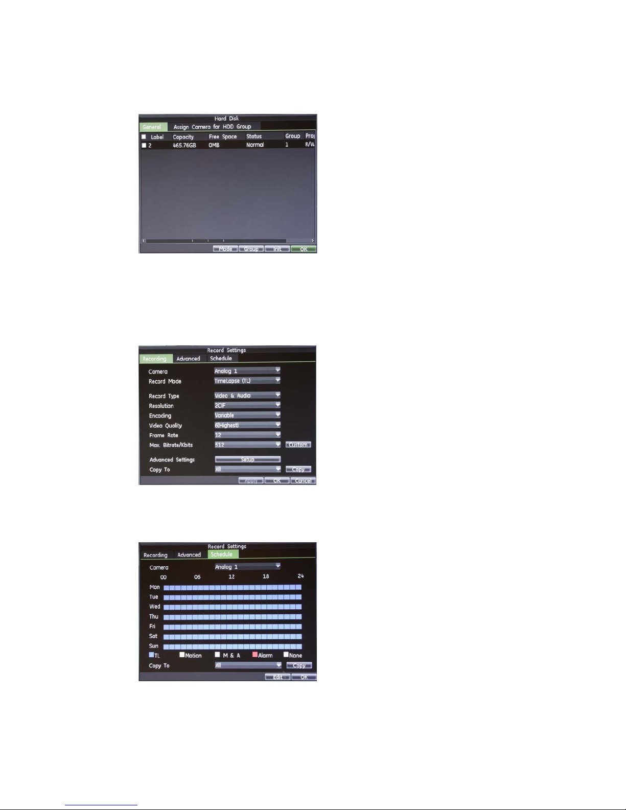
6. HDD management:
Click Enter to open the HDD Management screen and configure your HDD
settings as required.
Page 27
2BChapter 3: Getting started
TruVision DVR 60 User Manual 21
You can group HDDs and assign cameras to a group. See “Setting HDD
groups” on page 113. You can also set up a drive for redundant recording.
See “Setting the HDD to redundancy” on page 115.
After setting your HDD settings, click OK and then Next. You are then asked
if you want to enter the Record Settings screen.
7. Recording configuration:
Click Enter to open the Record Settings screen.
Under the Recording tab, select a camera and specify the camera settings.
Click the Schedule tab.
Click Edit.
Page 28
2BChapter 3: Getting started
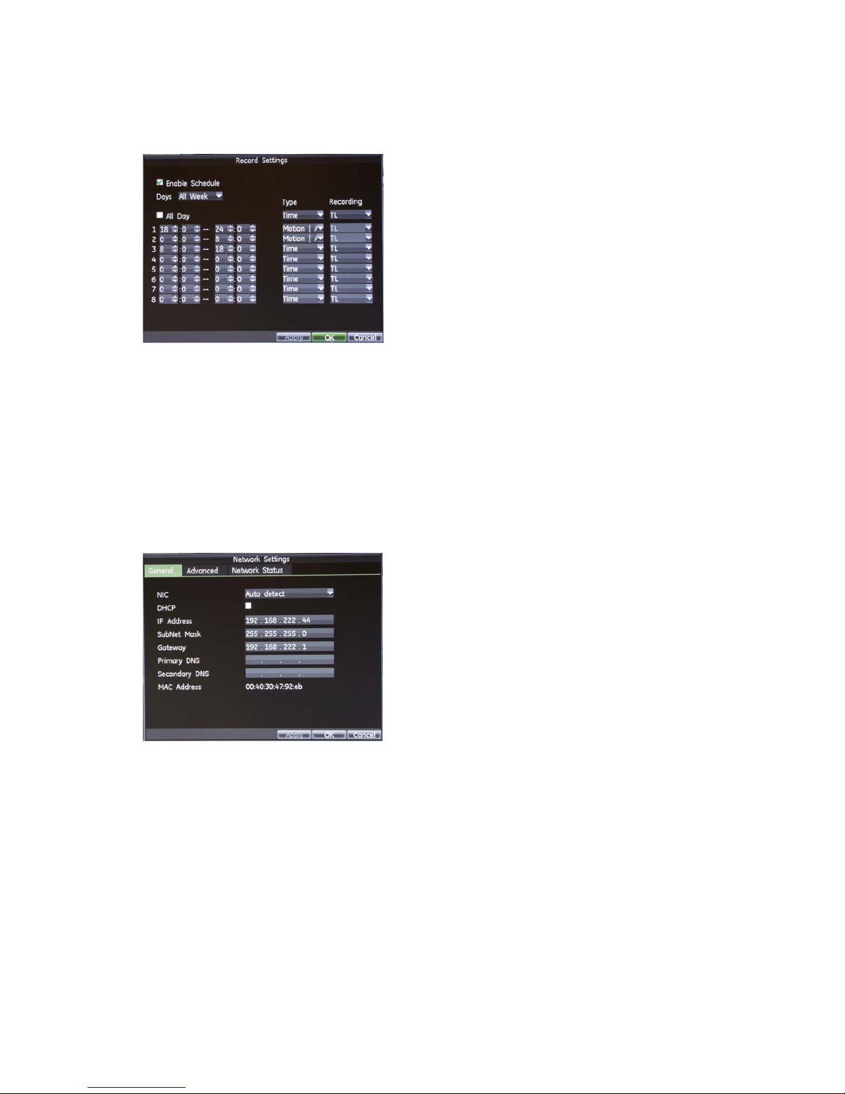
22 TruVision DVR 60 User Manual
Check both the “Enable Schedule” and “All Day” checkbox. This enables the
recording schedule. The DVR will record continuously all day for the whole
week.
Click OK to return to the Schedule tab. To copy the schedule to another
camera, select the camera or select “All” under Copy To and click the Copy
button.
Click OK and then Next. You are then asked if you want to enter the Network
Settings screen.
8. Network configuration:
Click Enter to open the Network Settings screen and define your network
settings such as the IP address, subnet mask and default gateway.
Click OK to return to the eZ Setup screen.
9. When all the required changes have been entered, click Finish to exit the
Setup Wizard. The TVR 60 is now ready to use.
Page 29

TruVision DVR 60 User Manual 23
Chapter 4
Operating instructions
Controlling the TVR 60
There are several ways to control the TVR 60:
• Front panel control
• Mouse control
• IR remote control
• KTD-405 / TVK-505U keypad control (see appendix)
• Web browser control (see Chapter 10 “Using the Web browser” on page 71
You can use your preferred control method for any procedure, but in most cases
we describe procedures using mouse terminology. Optional control methods are
given only when they differ substantially from mouse control methods.
Using the front panel
The buttons on the front panel control can be used to operate many, but not all,
of the main functions of the TVR 60 of the DVR functions. The LED indicators
light up or flash to alert you of various conditions. The functions available can be
limited by setting passwords. See Figure 9 on page 24 for more information.
Page 30
3BChapter 4: Operating instructions
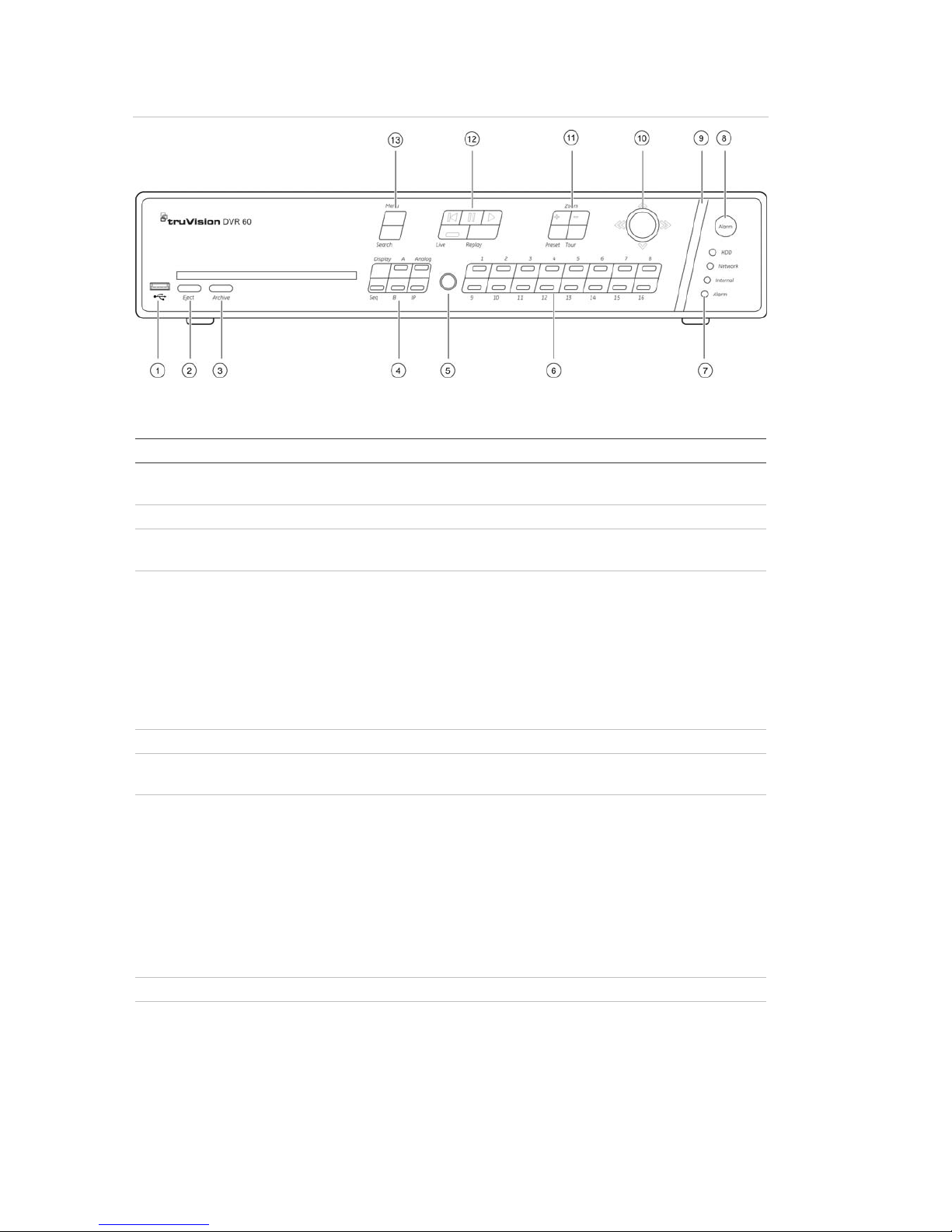
24 TruVision DVR 60 User Manual
Figure 9: Front panel
The controls on the front panel include:
Item Name Description
1. USB port Universal serial bus (USB) port for additional devices such
as USB mouse and USB hard disk drive (HDD)
2. Eject Ejects CD/DVD disc.
3. Archive Press once to enter quick archive mode. Press twice to start
archiving.
4. Display buttons Display: Toggles through the various multiscreens: full,
quad, 1+5, 1+7, 9, and 16.
Sequence: Starts/stops sequencing in live mode.
A: Selects monitor VGA/A in live mode
B: Selects monitor A/B in live mode
Analog: Displays the analog cameras
IP: Displays the IP cameras
5. IR receiver Receiver for IR remote
6. Numeric buttons Switch between different cameras in live, PTZ control or
playback modes.
7. Status LEDs HDD: Green indicates the DVR is working correctly. Red
indicates a fault.
Network: Green indicates the network is working correctly.
Red indicates a fault or no network connection.
Internal: Green indicates the Watchdog is working
correctly. Red indicates that the Watchdog is reporting a
fault.
Alarm: Green indicates no external alarm. Red indicates an
external alarm status or motion.
8. Alarm button Use to manually acknowledge an alarm.
9. Alarm indicator bar Blinking red indicates that there is an alarm.
Page 31

3BChapter 4: Operating instructions
TruVision DVR 60 User Manual 25
Item Name Description
10. Joystick
Use to select options in a menu and to control playback.
Press for Enter. Press LED arrows are lit when the jog is
active.
Live mode: Enter PTZ mode.
Menu mode: Move the joystick left/right and up/down to
position cursor in menu screen. Press for Enter.
Playback mode: Move the joystick left/right and up/down to
position cursor in menu screen. Press for Enter.
PTZ mode:
Rotate the joystick to control the movement of the PTZ
dome camera:
- Move left: Decrease speed.
- Move right: Increase speed.
- Move up: Jump forwards 30 seconds.
- Move down: Jump backwards 30 seconds.
11. PTZ buttons Zoom: Use + and – for digital zoom.
Preset: Call up preprogrammed preset positions.
Tour: Call up preprogrammed shadow tours.
12. Playback buttons
: Jump back to the oldest available video and starts the
playback.
: Pause playback.
: Instantly playback the currently selected file. Default
time is 1 minute.
Live: Switch to live mode.
Replay: Replay the current file in playback Starts at the
beginning of the file.
13. Menu and Search buttons Menu: Enter main menu.
Search: Enter advanced search menu.
Using the mouse
The USB mouse provided with the TVR 60 can be used to operate all the
functions of the DVR, unlike the front panel which has limited functionality. The
USB mouse lets you navigate and make changes to settings in the user
interface.
Connect the mouse to the TVR 60 by plugging the mouse USB connector into
the USB port on the rear panel. The mouse is immediately operational and the
pointer should appear.
Note: Use a USB 1.1 or higher mouse.
Move the pointer to a command, option, or button on a screen. Left-click the
mouse to confirm a selection.
You can purchase a spare mouse by ordering part number TVR-MOUSE-1
TruVision™ DVR Model 40/60 Mouse.
Page 32

3BChapter 4: Operating instructions
26 TruVision DVR 60 User Manual
To use a USB mouse:
1. Plug USB mouse into one of the USB ports on the front or rear panel of the
DVR.
2. The mouse should automatically be detected.
See Table 5 below for a description of the mouse buttons.
Table 5: Mouse buttons
Item Description
Left button Single-Click: Select a component of a menu, such as a button or an input field. This
is similar to pressing the Enter button on the remote/front panel controls.
Double-Click: Switch between single screen and multi-screen mode in live/ playback
mode.
Click and Drag: Click and drag the left mouse button to setup the alarm areas.
Right button Single-Click: Shows pop-up menu
Scroll-wheel Scroll Up: In Live mode, scrolling up will switch to the previous screen. In Menu
mode, it will move the selection to the previous item.
Scroll Down: In live mode, scrolling down will switch to the next screen. In Menu
mode, it will move the selection to the next item
Using the IR remote control
The TVR 60 is supplied with an infra red (IR) remote control unit. Like the mouse,
it can be used to operate all of the main functions of the TVR 60.
The IR remote control can be programmed with a unique device ID address so
that the controller will only be able to communicate with DVRs with that address.
No programming is necessary if using a single TVR 60.
The device ID address only applies when using a remote control and not when
using a keypad.
You can purchase a remote control by ordering part number TVR-REMOTE-1
TruVision™ DVR Model 40/60 IR Remote Control.
Page 33

3BChapter 4: Operating instructions
TruVision DVR 60 User Manual 27
Figure 10: IR remote control
Item Description
1. Alarm Acknowledge an alarm.
2. Device Enable/disable the IR remote control to control the TVR 60.
3. Numeric buttons Select a camera, and enter a number in a menu option.
4. Analog and IP Analog and IP buttons have the same function as on the front panel to select
between analog and IP cameras.
5. Display Toggle between the multiscreen views.
6. Mon A and Mon B Toggle between monitors A and B.
7. Live Return to live mode.
8. Menu Activate the main menu.
9. Seq Start /stop sequencing.
10. , , ,
In Menu mode: Use left or right arrow buttons to select and up or down arrow
buttons to edit entry.
In PTZ mode: Use to control PTZ.
In Playback mode: Use to control playback speed.
11. OK Confirm selection.
12. Zoom + and - Use to control zoom of camera lens.
13. Preset Enter preprogrammed three-digit code to call up a preset.
Page 34

3BChapter 4: Operating instructions
28 TruVision DVR 60 User Manual
Item Description
14. Tour Enter preprogrammed three-digit code to call up shadow tour.
15. Focus + and - Use to control focus of camera lens.
16. Playback control Use to control playback (Rewind, Pause, Play, and Fast Forward).
17. Search Open the Search menu.
18. Replay Replay the selected file from the beginning.
19. Eject Eject the CD or DVD disk.
20. Archive Press once to enter quick archive mode. Press twice to start archiving.
Aim the remote control at the IR receiver located at the front of the unit to test
operation.
To connect the remote control to the TVR 60:
1. Press the Menu button on the remote control or front panel or right-click the
mouse and select the Menu button. The main menu screen appears.
2. Click the Display icon.
3. Click the Monitor tab. The Monitor screen appears.
4. Check and remember the DVR device address value. The default value is
255. This device address is valid for all IR controls.
Note: The device address does not apply to keypads.
5. On the remote control press the Device button.
6. Enter the device address value. It must be the same as that on the TVR 60.
7. Press the ENTER button on the remote or front panel.
To place batteries into the IR remote control:
1. Remove the battery cover.
2. Insert the batteries. Make sure that the positive (+) and negative (−) poles are
correctly placed.
3. Replace the battery cover.
Troubleshooting the remote control:
If the IR remote control is not functioning properly, perform the following tests:
• Check the battery polarity.
• Check the remaining charge in the batteries.
• Check that the IR remote control sensor is not masked.
If the problem still exists, please contact your administrator.
Page 35

3BChapter 4: Operating instructions
TruVision DVR 60 User Manual 29
Main menu overview
The TVR 60 has an icon-driven menu structure that allows you to configure the
unit’s parameters. Figure 11 below shows the TVR 60 main menu screen. Each
command icon displays a screen that lets you edit a group of TVR 60 settings.
Most screens are available only to system administrators.
You must be in live mode to access the main menu.
The currently selected command icon is highlighted in green.
Figure 11: Main menu
Table 6: Description of the menu commands and options
Main menu command icon Description
Display Configures display settings including dwell time, schedule, language and
display formats.
Cameras Configures camera settings including motion detection, video image
adjustments, camera title, and copy settings to other cameras. See
Record Configures recording settings including recording schedules, record quality,
and record mode.
Network Configures standard network settings including IP address, e-mail
notifications, DDNS setup, and advanced network settings.
Alarms Configures alarm settings including alarm input, relay output, video loss,
remote alert, pre-alarm and post-alarm seconds.
PTZ Configures PTZ settings.
User Configures users, passwords, and access privileges.
Systems Configures system settings including system date and time, audio output,
device name, RS-485 settings, RS-232 settings, firmware upgrade, hard
drive settings, boot log, and shutdown.
Help Provides reference information to the various toolbars, menus, and keys
within the interface.
Page 36

3BChapter 4: Operating instructions
30 TruVision DVR 60 User Manual
To access the main menu:
1. Press the Menu button on the remote control or front panel or right-click the
mouse and select the Menu button. The main menu screen appears.
Press Exit in the main menu screen to return to live mode.
Navigating through a dialog screen
Use the mouse to select any option or button on the screen. You can also use
the joystick (Up, Down, Left, or Right) on the front panel to navigate through the
options and press Enter to select. Press Menu to return to configuration category
and icon.
Changes to screen settings can be entered in various ways as shown in Table 7
below.
Table 7: Types of control
Control Function Description
Edit box An edit box lets you type characters to set the
value of an option, such as a camera name. You
must be in edit mode before you can enter a value.
Click the box and a virtual keyboard will appear to
enter alphanumeric characters. See “Using the
virtual ke
yboard” below.
List box Provides more than two values for the option. Only
one of them can be selected. Click the scroll
arrows at the right-hand side of the box to scroll
through the possible values. Click an option to
then select it.
Check box Provides two values: indicates enabled and a
blank box indicates disabled. Click the check box.
Button Executes the function displayed on the button.
Click the button.
Bar Lets you adjust the scale of a value. Click and
hold the cursor. Adjust its position left or right
along the bar.
Using the virtual keyboard
A keyboard will appear on-screen when you need to enter characters in a screen
option. Click a key to input that character.
Figure 12: The virtual keyboard
Page 37

3BChapter 4: Operating instructions
TruVision DVR 60 User Manual 31
Description of the keys in the virtual keyboard:
Switch to Lowercase: Switch to lowercase input.
Switch to Uppercase: Switch to uppercase input.
Backspace: Delete the character in front of the cursor.
Enter: Confirm selection.
ESC: Exit out of Soft Keyboard.
Exiting the main menu
Press the Menu button on the front panel to exit the current menu screen.
Continue pressing the Menu button until you return to the live mode screen.
Page 38

3BChapter 4: Operating instructions
32 TruVision DVR 60 User Manual
Page 39

TruVision DVR 60 User Manual 33
Chapter 5
Live mode
Description of live mode
Live mode is the normal operating mode of the unit where you watch live pictures
from the cameras. The TVR 60 automatically enters into live mode once powered
up. On the display screen, you can see the current date and time, camera name,
and whether a recording is in progress.
Displaying status information
Information on the camera status is displayed on-screen as icons on the main
and spot monitors. The camera status icons are shown for each camera. These
icons include:
Table 8: Description of live lode camera status icons
Icon Description
M Yellow icon indicates detection.
R Green icon indicates continuous recording.
A Red icon indicates an alarm notification.
V Blue icon indicates video loss icon
The system status is displayed on the front panel by the status LEDs (see
Figure 9 on page 24).
Digital zoom
You can easily zoom in or out of a camera image in live mode and playback
using the digital zoom function. The zoom function magnifies the camera image
four times. See Figure 13 on page 34.
Page 40

4BChapter 5: Live mode
34 TruVision DVR 60 User Manual
Figure 13: Digital zoom screen
To quickly zoom in/out on a camera image:
1. Select the camera you wish to use.
2. Left-click the mouse and select the option Digital Zoom, or on the front panel
press the Zoom+ button. The digital view screen appears.
3. Left-click the mouse ands drag the red square to the area of interest, or move
the joystick on the front panel to position the red square. The selected area is
magnified.
4. To exit digital zoom right-click the mouse and select Exit, or press the
Zoom— button on the front panel.
Switching monitors
The TVR 60 can be connected to up to three monitors. However, only one
monitor can be controlled at a time. You can select from which monitor to display
the camera views in live mode.
Page 41

4BChapter 5: Live mode
TruVision DVR 60 User Manual 35
Table 9: Description of the monitor functions
3 monitors connected 2 analog monitors connected
Output Description Output Description
A Monitor VGA.
This is the main monitor. All features
can be accessed.
A Monitor A.
This is the main monitor. All features can
be accessed.
B Monitor A.
All features except the DVR
configuration can be accessed from
this monitor.
B Monitor B.
All features except the DVR configuration
can be accessed from this monitor.
Default spot monitor. Alarm pop-ups
appear on this monitor.
C Monitor B.
Default spot monitor. Alarm pop-ups
appear on this monitor.
Note: All monitors can be configured to display alarm pop-ups. See “Configuring
display options” on page 42.
To select a monitor:
1. On the front panel, press:
- 3 monitors connected: the A button to select monitor VGA or the B button
to select monitor A.
- 2 analog monitors connected: the A button to select monitor A or the B
button to select monitor B.
Pop-up menus for mouse operation
Many features of the live mode can be quickly accessed by placing the cursor on
a live image and clicking the right-button of the mouse (see Figure 14 below).
Figure 14: Live mode mouse pop-up menu for the main monitor
The list of features available depends on which monitor is active. See Table 10
on page 36.
Page 42

4BChapter 5: Live mode
36 TruVision DVR 60 User Manual
Table 10: Pop-up mouse menus
Item Name Description
1. Camera Switch to a full-screen view for the selected camera.
2. Multi View Switch between the different multiscreen options.
3. Next Screen Displays the next camera.
4. Talk Modify the audio volume or disable audio.
5. Playback Enter playback mode.
6. Monitor B Switch between monitors A (main) and B.
7. Menu Enter the Main menu.
Option is not available from monitor B.
8. Advanced
Search
Enter the advanced video search menu.
Viewing in full screen
Press the numeric button on the front panel to switch to the corresponding
camera display. For example, press button 10 to view camera 10.
Right-click the mouse and select Camera from the menu shown. Select the
camera required.
Viewing in multiscreen
A cameo is any cell in a multiscreen display. A camera picture can only be shown
in one cameo at a time. The TVR 60 has five multiscreen display formats
available as well as full screen. See Figure 15 below.
Configure which multiscreen display appears by default in the Display menu. See
“Configuring display options” on page 42.
Figure 15: Display formats
To select a multiscreen format:
1. Press the Display button on the front panel to cycle through different display
formats.
Page 43

4BChapter 5: Live mode
TruVision DVR 60 User Manual 37
You can also right-click the mouse and select MultiView from the menu.
Select the desired multiscreen display layout.
Sequencing cameras in live mode
The sequencing feature allows a camera to be displayed briefly on-screen,
before advancing to the next camera in the sequence list. Sequencing can only
be done in full screen mode.
Each camera on the main and spot monitors can have a pre-programmed dwell
time and sequence order. See “Sequencing cameras” on page 44 for the setup
information. The default sequence displays each camera in numerical order.
Sequencing live mode:
1. Select the camera where you want to start sequencing.
2. Press the Seq button on the front panel.
3. Press the Seq button again to stop the sequencing.
Cameo shortcuts
Regularly used features of live mode can be quickly accessed by clicking the leftbutton of the mouse. The Cameo shortcut pop-up menu appears (see Figure 16
below).
Figure 16: Cameo shortcut pop-up menu
Table 11: Cameo shortcut pop-up menu
Item Name Description
1. PTZ Enter PTZ control mode.
2. Audio Enable/Disable audio output. The audio option must already have been setup
in the Display menu.
Page 44

4BChapter 5: Live mode
38 TruVision DVR 60 User Manual
Item Name Description
3. Digital zoom Enter digital zoom.
4. Freeze Freeze the live image of the selected camera of the current display mode.
Although the image pauses, time and date information does not. The system
clock continues to run.
Page 45

TruVision DVR 60 User Manual 39
Chapter 6
Configuring the live mode
display
This chapter describes how to configure the on-screen image in live mode as
well as set up the DVR name and address, enable password protection, and set
up the system time and date.
You can change the settings in the screens in any order. They are described in
the following sections.
Configuring monitor and DVR options
Use this screen to configure the monitor image as well as to configure the DVR
name and address. See Figure 17 below.
The TVR 60 can support NTSC or PAL video output. The video format is auto
detected.
The VGA monitor is the main monitor by default and the spot monitor is monitor
C. When no VGA monitor is connected, the main monitor then becomes monitor
B.
Figure 17: Monitor setup screen
Page 46

5BChapter 6: Configuring the live mode display
40 TruVision DVR 60 User Manual
Table 12: Description of the Monitor setup screen
Option Description
Device name The name to use for the DVR.
Device address The device number to use for the DVR when programming the remote
control or keypad.
VGA resolution Define the VGA resolution.
Select one of the options from the drop-down list. Default is
1024×768/60 HZ.
Transparency menu Modify the transparency of the menus on-screen relative to the background
to make the menu screens easier to read or less prominent on-screen.
Default is non-transparent.
Select one of the options from the drop-down list.
Monitor standard The video standard used is auto detected.
Modify the video standard used to PAL or NTSC.
Monitor brightness Modify the video output brightness.
Mouse pointer speed Modify the speed of the mouse pointer.
Scaling monitor A / B Enable/disable the monitor display of the main (A) and spot (B) monitors
size to accommodate for differently sized monitors.
Password required Enable/disable system password.
DVR name and address
The DVR name is the name that appears on-screen such as during start up.
When you use the IR remote control or keypad to operate the TVR 60, the
TVR 60 must have a device address (bus ID). The default device address is 255
for a remote control.
If there is more than one DVR used, each device must have its own unique
device address as otherwise the IR remote control will control all the DVRs
together.
To configure the device name and address:
1. Enter the Display Settings screen by selecting Display in the main menu.
2. Click the Monitor tab. The Monitor screen appears.
3. In the Device Name box, enter a name for the TVR 60 unit. You can enter up
to 38 characters.
4. Click the Device address edit box. The virtual keyboard appears. Enter a
numeric value and click Enter. Up to eight digits can be entered. Default
address for the remote control is 255
5. Click the Apply button to save the settings.
6. Click OK to return to the main menu.
Page 47

5BChapter 6: Configuring the live mode display
TruVision DVR 60 User Manual 41
Monitor setup
To configure monitors:
1. Enter the Display Settings screen by selecting Display in the main menu.
2. Click the Monitor tab. The Monitor screen appears. Modify the required
settings. See Table 12 on page 40.
3. Click the Apply button to save the settings.
4. Click OK to return to the main menu.
Enabling a password
The Password Required option determines whether or not users must enter their
passwords to gain access to the different functions of the DVR.
To enable password access:
1. Enter the Display Settings screen by selecting Display in the main menu.
2. Click the Monitor tab. The Monitor screen appears.
3. Check the Password Required box to enable or disable the option.
4. Click the Apply button to save the settings.
5. Click OK to return to the main menu.
Configuring time and date
You can set up the date and time that will appear on-screen and time stamped
recordings. The start and end time of daylight savings time (DST) in the year can
also be set. DST is deactivated by default. See Figure 18 below for the Time
settings screen.
Figure 18: Time screen
Page 48

5BChapter 6: Configuring the live mode display
42 TruVision DVR 60 User Manual
Table 13: Description of the Time screen
Option Description
Time zone Select the time zone of the DVR from the drop-down list.
Date/time format Select the date format from the drop-down list. Default format is DD-MM-
YYYY.
Date/time Select the date and time to be displayed on-screen and saved on
recordings.
Click the date icon on the right of the date list box. A calendar appears.
Click the required date.
In the time row select the correct time to be displayed.
Menu timeout This is the length of time a menu is displayed on-screen. Only available for
the main monitor. Default is five minutes.
Select the required timeout period.
Enable DST Click the check box to enable or disable daylight savings time (DST).
From / to Set the duration of DST.
Enter the start and end dates and time for daylight savings.
DST BIAS Set the amount of time to move DST forward from the standard time.
Default is 60 minutes.
To set up the system time and date:
1. Enter the Display Settings screen by selecting Display in the main menu.
2. Click the Time tab. The Time screen appears. Modify the required settings.
3. Click the Apply button to immediately implement the changes.
4. Click OK to save the changes and return to the main menu.
Changing the instant playback time
You can quickly replay the last few minutes of recorded video. Use this menu to
set the exact replay period. The time options are between one to five minutes
from actual time. Default is one minute.
To change the instant playback time:
1. Enter the Display Settings screen by selecting Display in the main menu.
2. Click the Time tab. The Time screen appears.
3. In the Instant Playback box select the desired replay period.
4. Click OK to return to the main menu.
Configuring display options
Use this screen to set up the different monitors as well as the multiscreen, and
dwell time options. You can also enable audio output.
Page 49

5BChapter 6: Configuring the live mode display
TruVision DVR 60 User Manual 43
Figure 19: Layout screen
Table 14: Description of the layout screen
Option Description
Main monitor Select which monitor will be the main monitor. Default is VGA, if connected.
Layout mode Select which multiscreen layout will be default in live mode.
Main dwell time Set the length of time for which a camera appears on-screen on the selected
monitor before moving to the next camera during sequencing. Default is off.
Display layout Set the camera order during sequencing. See “Sequencing cameras” on page
44 for more information.
Enable audio out Enable/disable audio output.
Spot monitor Select which monitor will be the spot monitor. Default is B monitor.
Spot dwell time Set the length of time for which a camera appears on-screen on the spot (B)
monitor before moving to the next camera during sequencing. Default is 10
seconds.
To set up the display options:
1. Enter the Display Settings screen by selecting Display in the main menu.
2. Click the Layout tab. The Layout screen appears. Modify the required
settings.
3. Click the Apply button to save the settings.
4. Click OK to return to the main menu.
Audio set up
You can hear audio from cameras in both live and playback mode. However, in
order to be able to hear audio in playback you must select the Enable Audio
option in the Display menu.
To enable audio output:
1. Enter the Display Settings screen by selecting Display in the main menu.
2. Click the Layout tab. The Layout screen appears.
Page 50

5BChapter 6: Configuring the live mode display
44 TruVision DVR 60 User Manual
3. Enable/disable audio output
4. Click the Apply button to save the settings.
5. Click OK to return to the main menu.
Sequencing cameras
The cameras are sequenced in numeric order by default. You can change the
sequence order of the cameras for all monitors. However, if three monitors are
connected, monitor C sequencing cannot be started from the front panel.
You can switch the channel of a camera with that of another camera in the
system. This lets you, for example, have the images of camera 1 appear on
channel 10, and the images of camera 10 appear on channel 1. This feature is
useful when you want to watch the images from specific cameras next to each
other on-screen.
See Figure 20 below. Each cameo displays both the order of the camera in the
sequence and the camera number.
Figure 20: Camera layout and sequence screen
Multiscreen layout selection
Camera order in the sequence
Camera number selection
To set the camera sequencing:
1. Enter the Display Settings screen by selecting Display in the main menu.
2. Click the Layout tab. The Layout screen appears.
3. Select the desired monitor.
4. In the Display Layout option, click the Setup button. The Camera sequence
screen appears.
5. In the Layout Mode list box select the required multiscreen layout display.
6. Click the cameo of the camera whose order you want to change. The
selected cameo is highlighted green.
7. Click the scroll arrows alongside the camera number to move up or down the
list of camera numbers. Select a camera.
Page 51

5BChapter 6: Configuring the live mode display
TruVision DVR 60 User Manual 45
Note: “X” means that the camera is not displayed.
8. Click the OK button to accept the changes and return to the Layout screen.
9. Click the Apply button to see the results immediately implemented. Click the
Setup button again if further changes are required.
10. Click the OK button in the Layout screen to save changes and return to live
mode.
Page 52

5BChapter 6: Configuring the live mode display
46 TruVision DVR 60 User Manual
Page 53

TruVision DVR 60 User Manual 47
Chapter 7
Controlling a PTZ dome
camera
You can control PTZ dome cameras using the buttons on the front panel, the
keypad, and IR remote control as well as using the PTZ menu accessed with the
mouse. Access to PTZ functions may require a password.
Configuring PTZ settings
Use this screen to configure the PTZ dome cameras. Each camera must be set
up individually. Cameras must be configured before they can be used.
Ensure that the RS-485 port on the rear panel, which is used to set up the PTZ
dome cameras, and PTZ dome cameras are correctly connected.
Note: If a camera does not work correctly after configuring the DVR, check the
parameters entered.
Figure 21: PTZ settings screen
Page 54

6BChapter 7: Controlling a PTZ camera
48 TruVision DVR 60 User Manual
To configure PTZ dome camera settings:
1. Enter the PTZ Settings screen by selecting PTZ in the main menu.
2. In the Camera box, select the PTZ dome camera to be configured from the
drop-down list.
3. Select the baud rate, data bit, stop bit, parity and flow control for the camera.
The default values are:
Baud rate: 9600
Data bits: 8
Stop bits: 1
Parity: None
Flow control: None
Note: Click the Default button to return all values to default settings.
4. When all changes have been made, click the OK button to save the changes
and return to the main menu.
Assigning PTZ protocols
Assign a PTZ protocol and address to a camera to allow PTZ control of the
camera while in PTZ mode. See Appendix C “PTZ protocols” on page 135 for the
complete list of available protocols. The default protocol is GE RS-485.
To configure PTZ settings:
1. Enter the PTZ Settings screen by selecting PTZ in the main menu.
2. In the Camera box, select the PTZ dome camera to be configured from the
drop-down list.
3. Select a PTZ protocol in the PTZ protocol box.
4. Enter the PTZ address. Up to three digits can be entered. The number should
correspond with that used in the PTZ dome camera itself.
5. When all changes have been made, click the OK button to save the changes
and return to the main menu.
Copying settings to other cameras
PTZ dome camera settings can be copied to other PTZ dome cameras
connected to the DVR. In the Copy To option of the PTZ menu, select a
particular camera, or all cameras. Click Copy.
Page 55

6BChapter 7: Controlling a PTZ camera
TruVision DVR 60 User Manual 49
Pop-up menu for mouse operation
In PTZ mode use the mouse pop-up PTZ menu to get quick access to many PTZ
functions. Right-click the mouse to call-up the pop-up menu. See Figure 22
below.
Figure 22: Mouse pop-up PTZ menu
The items that can be found on this menu include:
Table 15: Description of the mouse pop-up PTZ menu
Item Name Description
1. Camera Select a PTZ dome camera.
2. Call preset Call up a preset position.
3. Call preset tour Call up a preset tour.
4. Call shadow tour Call up a shadow tour.
5. PTZ menu Open the PTZ menu.
6. Exit Exit PTZ mode.
Setting presets, preset tours and shadow
tours
You can customize presets, preset tours and shadow tours for a connected PTZ
dome camera.
Accessing PTZ mode
You can enter PTZ mode using the front panel, remote control, mouse and
keypad.
Front panel Press the joystick to Enter. PTZ control panel appears.
Mouse Right-click the mouse on the desired camera image. The mouse pop-up control
panel appears. Click the PTZ icon to enter PTZ mode. The PTZ control panel
appears.
Remote control Press the OK button. The PTZ control panel appears.
Keypad Press the Enter button on the keypad. For further information, see “Operating the
keypad” on page 142.
Page 56

6BChapter 7: Controlling a PTZ camera
50 TruVision DVR 60 User Manual
If the display was in multiscreen format, it changes to full screen format. See
Figure 23 below for a description of the PTZ control panel.
Figure 23: PTZ control panel
1. Directional pad/auto-scan buttons: Controls the movements and directions of the PTZ. Center button is used to start
auto-pan by the PTZ dome camera.
2. Adjust iris.
3. Adjust focus.
4. Adjust zoom.
5. Centers the PTZ dome camera. This function is not supported on all PTZ dome cameras.
6. Instant zoom in. This function is not supported on all PTZ cameras.
7. Adjust speed of PTZ dome camera movement.
Setting a preset position
Use the Preset tab in the PTZ Control screen to select, set, and delete presets.
Figure 24: Preset selection and setup screen
Page 57

6BChapter 7: Controlling a PTZ camera
TruVision DVR 60 User Manual 51
To set up a preset:
1. Enter PTZ mode by left-clicking the mouse on the desired camera image and
selecting the PTZ icon in the cameo shortcut menu.
- Or -
Press the front panel joystick for Enter.
The PTZ control panel appears.
2. Use the directional, zoom, focus and iris buttons to position the camera in the
desired preset location.
3. Click the Preset button on the PTZ control panel. The PTZ Control screen
appears with the Preset tab open.
4. Select a preset number and click the Set button. The preset is then enabled
and stored in the camera.
5. Click the OK button to save changes and return to PTZ mode.
To delete a preset:
1. Enter PTZ mode by left-clicking the mouse on the desired camera image and
selecting the PTZ icon in the cameo shortcut menu.
- Or -
Press the joystick for Enter on the front panel.
The PTZ control panel appears.
2. Click the Preset button on the PTZ control panel. The PTZ Control screen
appears with the Preset tab open.
3. Select a preset number and click the Clear button.
Note: The Clear All button deletes all presets.
4. Click the OK button to save changes and return to PTZ mode.
Setting a preset tour
Preset tours move a PTZ dome camera to different steps and have it stay there
for a set dwell time before moving on to the next point. The steps are defined by
presets (see “Setting a preset position” on page 50.)
Each preset tour consists of steps. A step consists of a step number, a dwell
time, and a speed.
The step number is th
e order the camera will follow while cycling through the
preset tour. The dwell time is the length of time for which a camera stays at a
step before moving to the next one. The speed is the rate at which the camera
will move from one step to the next.
Note: The PTZ dome camera used must be able to support a preset tour
function.
Page 58

6BChapter 7: Controlling a PTZ camera
52 TruVision DVR 60 User Manual
To set up a preset tour:
1. Enter PTZ mode by left-clicking the mouse on the desired camera image and
selecting the PTZ icon in the cameo shortcut menu.
- Or -
Press the front panel joystick for Enter.
The PTZ control panel appears.
2. Click the Preset Tour button on the PTZ control panel. The PTZ Control
screen appears with the Preset Tour tab open.
3. In the Preset Tour No. box select a preset tour to set.
4. In the list of presets, select the desired pre-programmed presets.
5. Click the Set button to enter the preset tour configuration menu. A preset tour
should have at least two enabled presets.
6. Set the step number, dwell time, and speed.
7. Click the OK button to return to the preset tour configuration men.
8. Repeat steps 2 to 7 to configure other steps.
9. After all steps have been configured, click OK to save and return to PTZ
mode.
To delete a preset tour:
1. Enter PTZ mode by left-clicking the mouse on the desired camera image and
selecting the PTZ icon in the cameo shortcut menu.
- Or -
Press the front panel joystick for Enter.
The PTZ control panel appears.
2. Click the Preset Tour button on the PTZ control panel. The PTZ Control
screen appears with the Preset Tour tab open.
3. Select a preset tour number and click the Clear button.
Note: The Clear All button deletes all presets.
4. Click the OK button to save changes and return to PTZ mode.
Setting a shadow tour
The Shadow Tour function remembers the PTZ dome camera movement track.
Only one shadow tour can be set up.
Note: The PTZ dome camera must be able to support a shadow tour function.
To set up a shadow tour:
1. Enter PTZ mode by left-clicking the mouse on the desired camera image and
selecting the PTZ icon in the cameo shortcut menu.
Page 59

6BChapter 7: Controlling a PTZ camera
TruVision DVR 60 User Manual 53
- Or -
Press the front panel joystick for Enter.
The PTZ control panel appears.
2. Click the Shadow Tour button on the PTZ control panel. The PTZ Control
screen appears with the Shadow Tour tab open.
3. Select the shadow tour number from the list displayed.
Note: There is only one shadow tour.
4. To record a new shadow tour, click the Run Shadow button to start recording
of the movements of the PTZ. Use the PTZ control panel to move the camera.
The camera movements will be recorded until the Stop Running button is
clicked.
5. Click the OK button to save and return to PTZ mode.
Calling up a preset position
Presets are previously defined locations of a PTZ dome camera. It allows you to
quickly move the PTZ dome camera to a desired position. You must be in live
mode to call up presets.
Note: Only enabled presets can be called up and deleted.
To call up a preset using the mouse:
1. Enter PTZ mode by left-clicking the mouse on the desired camera image and
selecting the PTZ icon in the cameo shortcut menu. The PTZ control panel
appears.
2. Click the Preset button on the PTZ control panel. The PTZ Control screen
appears with the Preset tab open.
3. Select a preset number and click the Call button.
4. Click OK. The camera immediately moves to that preset position.
To call up a preset using the front panel:
1. Enter PTZ mode pressing the joystick for Enter on the front panel. The PTZ
control panel appears.
2. Click the Preset button on the front panel.
3. Enter a preprogrammed preset number. The camera immediately moves to
that preset position.
Page 60

6BChapter 7: Controlling a PTZ camera
54 TruVision DVR 60 User Manual
Calling up a preset tour
To call up a preset tour:
1. Enter PTZ mode by left-clicking the mouse on the desired camera image and
selecting the PTZ icon in the cameo shortcut menu. The PTZ control panel
appears.
2. Click the Preset Tour button. The PTZ Control screen appears with the
Preset Tour tab open.
3. Select an enabled preset tour number and click the Start button.
To stop the preset tour, click the Stop button.
Calling up a shadow tour
To call up a shadow tour using the mouse:
1. Enter PTZ mode by left-clicking the mouse on the desired camera image and
selecting the PTZ icon in the cameo shortcut menu. The PTZ control panel
appears.
2. Click the Shadow Tour button. The PTZ Control screen appears with the
Shadow Tour tab open.
3. Select the enabled shadow tour number and click the Run Recor d button.
To call up a shadow tour using the front panel:
1. Enter PTZ mode pressing the joystick for Enter on the front panel. The PTZ
control panel appears.
2. Click the Tour button on the front panel. The shadow tour starts.
Page 61

TruVision DVR 60 User Manual 55
Chapter 8
Playing back a recording
The TVR 60 lets you to quickly locate and playback recorded video. There are a
few ways to playback video:
Instant playback of recorded video
Search the video archives by specific time, date, or event,
Search the system log
The DVR continues to record the live mode from a camera while simultaneously
playing back video on that camera display. Access to playback functions may
require a password.
You must be in live mode to playback video.
Figure 25: Playback screen
1. Running playback with date and time
2. Camera control panel. Used to select up to four
cameras for playback
3. Calendar control panel.
Green: Current date
Blue: Recordings available on the unit
4. Playback control panel
Page 62

7BChapter 8: Playing back a recording
56 TruVision DVR 60 User Manual
The playback control panel
It is easy to select the start and end playback times using the playback control
panel. See Figure 26 below.
Figure 26: Playback control panel
1. Audio on/off
2. Start/stop video clip during playback. Sections of a
recording can be saved to an external storage device.
3. Previous file/day/event recording
4. Reverse playback by 30 seconds
5. Play/pause playback
6. Stop playback
7. Fast forward playback by 30 seconds
8. Increase playback speed. Options available are:
single frame, 1/8 speed, ¼ speed, ½ speed, normal,
X2 speed, X4 speed, X8 speed, maximum speed.
9. Decrease playback speed: Options available are:
single frame, 1/8 speed, ¼ speed, ½ speed, normal,
X2 speed, X4 speed, X8 speed, maximum speed.
10. Play next file/day recording in the search result
11. Timeline: The timeline moves left (oldest video) to
right (newest video). Click a location on the timeline to
move the cursor to where you want playback to start
12. Type of recording: Blue line indicates continuous
recording. Red line indicates alarm/event recording
13. Quit playback and return to the Search screen
14. Hide the camera/date control panel
15. Hide the playback control panel
Playing back recorded video
You can easily search for recorded videos for playback. See Figure 28 on page
58.
You can playback up to four cameras at once. However, when using megapixel
cameras you can only playback two megapixel cameras with a resolution greater
than 4 CIF. If the resolution is less than or equal to 4 CIF, you can playback up to
four megapixel cameras.
All multiscreen cameras in playback play simultaneously. This means, for
example, that it is easy to follow the path of an intruder who has passed in front
of several cameras.
Page 63

7BChapter 8: Playing back a recording
TruVision DVR 60 User Manual 57
Figure 27: Advanced Search screen
Table 16: Description of functions in the Advanced Search screen
Function Description
Analog / IP camera status Displays all the analog and IP cameras set up in the system. A search can
include both analog and IP cameras. At least one camera must be selected in
a search.
Use to select the cameras to include in the search.
Video type Search for the type of event. The options available are: Time, Motion, Alarm,
Motion or Alarm, Motion and Alarm, All.
Protected Files found in a search can be protected against being subsequently deleted.
Locked files cannot be deleted. There are three file protection options:
Locked, unlocked, all. Unlocked is default.
Use to select the protection status of a recording.
Start time Use to select the start time and date for the search.
Details Provides a detailed view of the type of events recorded on the selected
camera or cameras over one day. The Detail screen can be used to narrow
the time window in a day to be searched. Use the mouse to move the left
green bar to change the search start time and the right blue bar to change the
search end time.
Click the Details button to enter the Detail sub-screen. If any changes are
made to the position of the green or blue bars, click OK and return to the
Advanced Search screen.
End time Use to select the end time and date for the search.
Export Use to archive selected files onto a storage device such as a USB.
Search results
A search will usually produce a list of files, which may extend to several pages.
The files are listed by camera, and then for each camera by date and time. The
oldest file is listed first. See Figure 28 on page 58 for an example of a search.
Only one file can be played back at a time.
Files can be locked by selecting a camera entry, which becomes highlighted, and
clicking the Lock button. The icon in the Protected column then changes.
Page 64

7BChapter 8: Playing back a recording
58 TruVision DVR 60 User Manual
Figure 28: Example of a search result list
Playing back files from a video search
To playback from one camera:
1. In live mode, select the camera display for playback.
2. Press the Search button on the remote control or front panel, or right-click the
mouse and select the Advanced Search button. The Advanced Search
screen appears.
3. In the Analog and/or IP Camera Status lines use the joystick to move the
cursor to a camera check box and press Enter to select the desired camera.
You can also use the mouse to click a camera’s check box.
4. Using the joystick, move the cursor to each of the search parameters and
select the options required. In the option box press Enter on the front panel to
accept the change. You can also use the mouse to modify the parameters.
5. Click the Search button. The list of search results appears.
6. Using the joystick, move the cursor to the first line of the search results and
press Enter to select. The line is highlighted green. To select a different
search result line, move the cursor to the desired line and press Enter again.
You can also use the mouse to select a search result line.
Note: Only one line can be selected.
7. Press Play. The selected recording plays back immediately.
8. To stop playback, right-click the mouse and select the Exit button in the
playback control panel.
To hide the playback control panel during playback, right-click the mouse and
select the Control Panel button in the playback control panel.
9. When playback has finished, click Exit to the Search screen. Another search
result can be selected.
Page 65

7BChapter 8: Playing back a recording
TruVision DVR 60 User Manual 59
To playback from more than one camera:
1. In live mode select the camera display for playback.
2. Press the Search button on the remote control or front panel, or right-click the
mouse and select the Advanced Search button. The Advanced Search
screen appears.
3. Use the front panel joystick to move the cursor to a camera check box and
press Enter to select the desired cameras. You can also use the mouse to
click a camera’s check box.
4. Using the joystick, move the cursor to each of the search parameters and
select the options required. In the option box press Enter on the front panel to
accept the change. You can also use the mouse to modify the parameters.
5. Click the Search button. The list of search results appears.
6. Using the joystick, move the cursor to the first line of the search results and
press Enter to select. The line is highlighted green. To select a different
search result line, move the cursor to the desired line and press Enter again.
You can also use the mouse to select a search result line.
Note: Only one line can be selected.
7. Click the Play button. The Synchronous Playback Cameras screen appears
which lists all the selected cameras. (The example below shows analog
cameras only.)
8. Select up to four analog or two IP cameras to playback simultaneously and
press the OK button.
The selected cameras play back immediately.
9. To stop playback, right-click the mouse and select the Exit button in the
playback control panel.
To hide the playback control panel, right-click the mouse and select the
Control Panel button in the playback control panel.
10. When playback has finished, click Exit. Another search result can be
selected.
Page 66

7BChapter 8: Playing back a recording
60 TruVision DVR 60 User Manual
To do digital zoom in playback:
You can zoom in on an image during playback. During playback right-click the
mouse to call-up the playback control panel. Click the Zoom button to enter
digital zoom.
To hide the playback control panel:
To hide the playback control panel during playback right-click the mouse and
select the Control Panel button.
To exit playback mode:
1. Press the Live button on the front panel to exit playback mode and return to
live mode.
- Or -
Right-click the mouse and select Exit from the pop-up menu.
- Or -
Click the Exit icon in the bottom right corner of the playback control panel.
Instant replay of recorded video
Use the playback toolbar to quickly replay recorded video from the last few
minutes. This can be useful to review an event that has just happened. The exact
instant replay period of can be modified in the Display menu (see “Changing the
instant playback time” on page 42.)
To instantly replay recorded video:
• Using the mouse:
1. In live mode right-click the mouse on the desired camera image. The mouse
pop-up control panel appears. Click the Playback button to enter playback
mode.
2. Playback from the selected camera starts in full-screen mode immediately
from the pre-programmed time period for instant playback.
Note: A message appears if there are no recordings found during this period.
3. To include other cameras in the playback, click the camera type tab
(Analog/IP) in the camera control panel and then select up to four cameras
from the list.
Page 67

7BChapter 8: Playing back a recording
TruVision DVR 60 User Manual 61
Click the Stop button on the playback control panel and then click Play to
restart playback. Playback restarts in multiscreen view.
• Using the front panel/remote control:
1. In live mode press the Playback button on the front panel or remote control to
enter playback mode.
2. Press the Analog or IP button to select the camera type.
3. Press the camera number button for the desired camera.
Note: Multiscreen playback is only available using the mouse.
4 Playback from the selected camera starts immediately from the pre-
programmed time period for instant playback.
Note: A message appears if there are no recordings found during this period.
Playing back from the system log
You can also playback recordings from the system log. The system log provides
a much wider range of options for playback than Advanced Search, which deals
with video detection and alarms only.
Figure 29: View log screen
Page 68

7BChapter 8: Playing back a recording
62 TruVision DVR 60 User Manual
To playback video from the system log:
1. Press the Menu button on the remote control or front panel, or right-click the
mouse and select the Menu button. The main menu screen appears.
2. Click the System icon. The System View screen appears.
3. In the View Log box, click the View button. The View Log screen appears.
4. In the Major Type box, select an option from the drop-down list.
5. In the Minor Type box, select an option from the drop-down list. The list of
options available depends on the option selected under Major Type.
6. In the Start Time and End Time boxes, select the start and end times for the
recordings to play back.
7. Click the Search button. A list of results appears.
8. Select the video file to playback and click the:
- Details button: For more information on the recording. It lists such
information as start time, type of information, camera number, and gives a
description on the types of events recorded and when record time was
stopped.
- Play button: Click to start playback of the recording.
- Export button: Click to archive the file. The export screen appears.
- Cancel: Click to return: to the previous screen.
Playing back frame-by-frame
You can easily playback a selected video at different speeds. This allows you to
carefully examine an event, for example, frame-by-frame as it happens.
To playback frame-by-frame in playback mode:
• Using a mouse:
1. In the playback screen click the Speed Down button on the playback control
panel until the speed changes to Single frame.
2. Click the Pause button to advance the video frame by frame.
Page 69

7BChapter 8: Playing back a recording
TruVision DVR 60 User Manual 63
• Using the front panel/remote:
1. In the playback screen move the joystick to left to scroll down through the
speed changes until Single frame.
2. Press Enter with the joystick to advance the video frame by frame.
3. Press the Playback button to do continue playback at normal speed.
Exiting playback mode
To exit playback mode, press Menu on the front panel or remote control, or rightclick the mouse and select the Menu button.
Page 70

7BChapter 8: Playing back a recording
64 TruVision DVR 60 User Manual
Page 71

TruVision DVR 60 User Manual 65
Chapter 9
Archiving recorded files
Archive recorded files on an external device such as a USB flash drives, USB
HDDs, eSATA device or a DVD writer. You must be in live mode to archive
video. Access to archive functions may require a password.
Note: The USB port on the rear panel does not support USB CD/DVD burners or
USB HDDs.
Archiving files
There are two ways to archive files:
Quick Archive: Quick archive lets you archive recorded files quickly by using the
Archive button on the front panel. The TVR 60 then downloads all the recorded
files on the unit to fill the available memory space on the media. This option is not
available via the mouse.
Advanced Search screen: Use the Export function in the Advanced Search
screen to specify archiving settings such as a specific time and date period as
well as cameras.
Using Quick Archive
To archive recorded video using Quick Archive
1. Insert the backup device into the TVR 60.
If using a USB memory drive, insert the device into the USB port on the front
panel. If using a digital video disk (DVD) or eSATA drive, insert the disc into
the DVD drive. If more than one media type is found in the TVR 60, the USB
device takes precedence over the others.
2. Press Archive to open the archive screen.
3. Press the Archive button on the front panel or remote control. The unit starts
to download the files.
A message will appear to confirm when the download is complete.
Page 72

8BChapter 9: Archiving recorded files
66 TruVision DVR 60 User Manual
Exporting recorded files to a backup device
You can insert a mini-USB hub to the USB port to attach a mouse for navigation
and a USB drive for archiving. However, the unit may not support all types of
USB hubs.
Figure 30: Export screen
Table 17: Description of the Export screen
Item Function Description
1. Refresh Refresh the search results if any parameters have been modified.
2. Media Select one of the storage media for archiving: USB flash drive, USB
HDD, or DVD writer). If the backup device is not recognized:
• Click the Refresh button.
• Reconnect device.
• Check for compatibility from vendor.
3. Free space Free space available on the backup device is displayed.
4. File Files found on the backup device are listed.
5. New Create new folder.
6. Delete Delete selected file.
7. Play Play selected file.
8. Format Format the USB/eSATA drive.
9. Start Start downloading selected files onto storage medium.
10. Cancel Cancel search and return to previous menu.
Page 73

Chapter 9: Archiving recorded files
TruVision DVR 60 User Manual 67
To export recorded files to a backup device:
1. Connect the backup device to the DVR.
If using a USB memory drive, insert the device into the USB port on the front
panel. If using a digital video disk (DVD) or eSATA drive, insert the disc into
the DVD drive. If both media are found in the TVR 60, the USB device takes
precedence over the DVD.
2. In live mode press the Search button on the remote control or front panel, or
right-click the mouse and select the Menu button and the Playback button.
The Advanced Search screen appears.
3. In the Analog Status line, select the cameras.
4. Select the search parameters
Function Description
Video type Search for the type of event or file. The options available are: Schedule,
motion detection, alarm or motion detection and/ alarm, manual
recording, all.
Select an option from the drop-down list.
Protected When a file is locked, the search results display “Locked” in the Major
column. Locked files cannot be deleted.
Select an option from the drop-down list.
Start time Select the start time and date for the search.
Details Provides a detailed view on camera recordings.
End time Select the end time and date for the search.
5. Click the Search button. The list of results appears.
6. Click the video file or files to export.
Note: You can click the Play button to verify that the selected files are the
files to export.
7. Press the Export button. The Export screen appears.
The size of the currently selected files is displayed in the upper-right corner of
the screen.
8. Select the storage medium to export to from drop-down list.
9. Click the Start button to begin the backup process.
Page 74

8BChapter 9: Archiving recorded files
68 TruVision DVR 60 User Manual
10. After the backup process has completed, you may select the files from your
device and click the Play button to verify that it has been exported
successfully.
Archiving video clips
You can save important scenes in a recorded file for later reference by creating
video clips of selected portions of the file during playback. When an intruder, for
example, crosses in front of several cameras you can save the video clip of the
intruder’s path across these cameras in a single file.
Note: This feature is only available using the mouse.
To export video clips during playback:
1. Connect the backup device to the TVR 60.
2. Search for the required files to playback. See “Playing back files from a video
search” on page 58.
3. Select the file to playback and press the Play button. Playback starts
immediately.
4. Click the playback timeline where you want the video clip to start and click the
Start Clip button.
5. Click the playback timeline where you want the video clip to stop and click the
End Clip button.
6. Repeat for additional clips.
7. Click the Quit Playback button to quit playback mode. A message appears
asking if you want to save the video clips.
8. Click Yes to archive the clips. The Export screen appears.
Click No to exit and return to the search results screen.
9. In the Export screen select from the drop-down list the backup device to be
used.
10. Click the Start button. File downloading starts.
Note: You can create a new folder for the video clips. Press the New Folder
button and enter the folder name.
Managing backup devices
You can manage backup devices from the Export screen (see Figure 30 on page
66.)
The Export screen allows you to:
Page 75

Chapter 9: Archiving recorded files
TruVision DVR 60 User Manual 69
• Create New Folder: Creates a new folder on the backup device.
• Delete: Delete a file or folder from the backup device.
• Play: Play the selected video file from the backup device.
• Format: Format the backup device.
• Erase: Erase files from a re-writable CD/DVD.
Playing back archived files on a PC
Use the standard file player software to play back the archived video on your PC.
It can be downloaded from the TVR 60 when archiving files onto a backup
device.
Page 76

8BChapter 9: Archiving recorded files
70 TruVision DVR 60 User Manual
Page 77

TruVision DVR 60 User Manual 71
Chapter 10
Using the Web browser
This chapter describes how you can use the Web browser interface to configure
the device, play back recorded video, search through event logs, and control a
PTZ dome camera. You can also specify settings on the Web browser interface
to optimize video playback and recording performance when operating in a low or
limited bandwidth environment.
Windows Vista and 7 users
Internet Explorer for Windows Vista and Windows 7 operating systems have
increased security measures to protect your PC from any malicious software
being installed. When using the TVR 60 Web browser interface, you can install
ActiveX controls to connect and view video using Internet Explorer.
To have complete functionality of the Web browser interface and the DVR player
with Windows Vista and Windows 7, do the following:
• Run the Browser interface and the DVR player application as an administrator
in your workstation
• Add the DVR’s IP address to your browser’s list of trusted sites
To add the DVR’s IP address to Internet Explorer’s list of trusted sites:
1. Open Internet Explorer.
2. Click Tools, and then Internet Options.
3. Click the Security tab, and then select the Trusted Sites icon.
4. Click Sites.
5. Clear the “Require server verification (https:) for all sites in this zone” box.
6. Enter the IP address or DDNS name in the “Add this website to the zone”
field.
7. Click Add, and then click Close.
8. Click OK in the Internet Options dialog screen.
9. Connect to the TVR 60 for full browser functionality.
Page 78

9BChapter 10: Using the Web browser
72 TruVision DVR 60 User Manual
Accessing the Web browser
To access the TVR 60, open a Web browser and enter the IP address assigned
to the TVR 60, as a Web address. On the logon screen, enter the default user ID
and password.
Note: Only one DVR can be viewed per browser.
User ID: admin
Password: 1234
The Web browser uses the following ports.
• IP address - 192.168.1.82
• Subnet mask - 255.255.255.0
• Gateway address - 192.168.1.1
• Video Port: 8000
• HTTP Port: 80
Web browser overview
The TVR 60 Web browser lets you view, record, and play back videos as well as
manage all aspects of the DVR from any PC with Internet access. The browser’s
easy-to-use controls give you quick access to all TVR 60 functions. See
Figure 31 on page 73.
Page 79

9BChapter 10: Using the Web browser
TruVision DVR 60 User Manual 73
Figure 31: Web browser interface
Table 18: Description of the Web browser screen
Item Name Description
1. Menu toolbar Lets you do the following:
• View live video
• Play back video
• Search for event logs
• Configure settings
• Exit the interface
2. Viewer View live or playback video.
3. PTZ controls Control PTZ for the currently selected camera.
4. Camera View video and record video from the selected camera.
5. Display layout Define how you want video to be displayed in the Viewer.
6. Video function Lets you do the following:
• Record live video
• Take a snapshot of video
• Enable recording for all cameras
• Display previous camera view
• Display next camera view
7. Audio setting Turn audio on or off.
8 Video image settings Adjust video image settings such as brightness, contrast,
saturation, and hue. You can restore these settings to default.
Page 80

9BChapter 10: Using the Web browser
74 TruVision DVR 60 User Manual
Using the Web browser to configure the
device
Click Config on the menu bar to display the configuration screen. There are two
ways to configure the DVR: Local and Remote.
Local configuration
Local configuration lets you define communication and network parameters such
as protocol type, maximum file size, stream type, network transmission settings.
You can also specify the directory locations for saving recorded and playback
video, captured images, and downloaded files.
Remote configuration
Remote configuration lets you remotely configure the following DVR settings:
Note: The configuration settings defined remotely are different from those that
can be defined locally.
Figure 32: Remote browser configuration screen (Video parameters shown)
Caution: You can adjust the frame type and I-frame ratio of the camera
streaming configuration (see the boxed area in Figure 32). However, these
settings have a direct impact on the recorded video quality and streaming
behavior. Changing the factory default settings can result in loss of streaming
performance and poor video quality. It is strongly recommended that the factory
default values are not changed.
• DVR information including device name, number, and display scale
Page 81

9BChapter 10: Using the Web browser
TruVision DVR 60 User Manual 75
• Camera settings including motion detection, privacy masking, video loss,
video tampering, video image display settings, and text overlay
• Recording settings including recording schedule and recording quality
• Network settings including, e-mail, DDNS, and NTP setup
• Serial port settings including RS-485 and RS-232 parameters
• Alarm settings including alert notifications, audio alerts, pre-alarm, and postalarm seconds, and notification parameters
• System settings including, user management, date and time, audio, RS-485,
RS-232, language, alarm notification and hard drive setup
The remote configuration screen also lets you remotely upgrade the DVR
firmware. See Figure 32 on page 74.
Searching and playing back recorded video
To search and play back recorded video, click Playback on the menu bar to
display the Playback page shown in Figure 33 on page 76.
Page 82

9BChapter 10: Using the Web browser
76 TruVision DVR 60 User Manual
Figure 33: Browser playback page
1. Calendar. Selected day is highlighted
2. Selected camera
3. Playback control toolbar
4. Timeline (TL). Indicates video recorded for the
specified day as well as type of recording
5. Click to capture a snapshot of the video
6. Click to save the video playback
7. Type of recording:
Blue: Indicates video recorded based on the
recording schedule defined.
Red: Indicates video recorded triggered by an alarm
event.
8. Click to download the recorded video
9. Click to start Search
Select a camera and a day to search from on the calendar displayed, and then
click Search. The timeline below the page indicates video recorded for the
specified day. The timeline also classifies by color the type of recording with each
type.
Click and drag the marker across the timeline on where you want video playback
to begin, and then click Play on the playback control toolbar. You can capture a
snapshot of a video image, save the video playback, or download the recorded
video.
Page 83

9BChapter 10: Using the Web browser
TruVision DVR 60 User Manual 77
Searching for event logs
The DVR compiles a log of events, such as the start or end of video recording,
DVR notifications, and alarms, through which you can easily search. Logs are
categorized by the following types:
• Alarm: Includes motion detection, tamper detection, video tampering, and
other alarm events
• Notifications: Includes system notifications such as video loss, HDD failures,
and other system-related events
• Operations: Includes users access to the Web interfaces and other
operational events
• Information: Includes general information on the DVR actions, such as the
start and end of video recording, etc.
To search for logs, click Log on the menu bar, select a log type, specify a date
and time range, and then click Search.
Live dual streaming
The TVR 60 allows you to view from up to 16 cameras over a network. Dual
streaming allows high quality video to be viewed in one stream (Stream A) and
lower quality video to be viewed in another stream (Stream B) that can be easily
streamed through a narrow bandwidth.
Dual streaming is only available in live mode using the browser. You cannot
record.
To access live dual streaming via the browser:
1. In the Web browser interface right-click the mouse on the video image.
A pop-up box appears asking about dual stream selection.
2. Select main or substream option.
Controlling a PTZ dome camera in the Web
browser
The Web browser interface lets you control the PTZ functions of a dome camera.
Click on a PTZ dome camera and use the PTZ controls on the interface to control
the PTZ functions.
Page 84

9BChapter 10: Using the Web browser
78 TruVision DVR 60 User Manual
Figure 34: PTZ controls
1. Directional pad/auto-scan buttons: Controls the movements and directions of the PTZ. Center button is used to start
auto-pan by the PTZ dome camera.
2. Select preset function.
3. Adjust zoom, focus, and iris.
4. Adjust speed of PTZ dome camera movement.
5. Start preset function.
Page 85

TruVision DVR 60 User Manual 79
Chapter 11
Configuring recording
settings
This chapter provides instructions on how to define the recording settings of your
DVR. This chapter covers how you can configure your initial recording settings,
schedule recordings, protect your recorded files, and set up your HDD for
redundancy.
Initializing recording settings
Before you can set up your DVR to begin recording, you must first configure
general recording settings for the analog cameras.
Note: IP cameras cannot be configured from the DVR. IP cameras are
configured from the IP camera itself. Refer to the user manual provided with your
IP cameras for more information.
To configure recording settings:
1. Enter the Record Settings screen by selecting Record in the main menu.
2. In the Recording tab screen select the camera for which you want to
configure settings.
Page 86

10BChapter 11: Configuring recording settings
80 TruVision DVR 60 User Manual
3. Configure the following settings:
• Record Mode: Select the encoding parameters, either Timelapse (TL),
Alarm, or Schedule.
• Record: Select the type of stream to record, either video or video and
audio.
• Resolution: Select the resolution of the recording. Options include: 4CIF,
2CIF, CIF, and QCIF.
• Encoding: Select either Variable or Constant bit rate.
• Video Quality: Select the quality at which to record.
• Frame Rate: Select the recordings frame rate. Full (PAL is 25 FPS and
NTSC is 30FPS), 20, 16, 12, 10, 8, 6 (default), 4, 2, 1, 1/2, 1/4, 1/8, 1/16.
• Max Bit Rate: Select or define the custom maximum bit rate for
recordings. The maximum bit rate must be calculated from your camera,
background, and image quality requirements.
4. Click Setup under Advanced Settings to display the advanced recording
settings.
5. Set the following advanced record settings:
• Pre-recording: Select the time in seconds to pre-record before the actual
recording begins.
• Post-recording: Select the time in seconds to post-record after the actual
recording has ended.
• ADM: Select the expiration time in days for recorded video. Recordings
after expiration time are deleted. If it is set to ‘0,’ the option is disabled.
• Redundancy: Specify whether to enable or disable redundant recording
on the particular camera.
• Record Audio: Specify whether to record audio of the camera or not.
6. Click OK to save your changes and return to the previous screen.
7. Click the Advanced tab to open the Advanced settings menu.
• Overwrite: Enable or disable the Overwrite setting. Enabling this setting
causes recorded files to be overwritten once the HDD is full.
Page 87

10BChapter 11: Configuring recording settings
TruVision DVR 60 User Manual 81
• e-SATA: Select Backup or Storage Expansion.
8. Click Apply, and then OK to save your changes.
Defining a recording schedule
Defining a recording schedule lets you specify when the DVR records video and
under what circumstances. Each camera can be configured to have its own
recording schedule.
A recording schedule can be set for analog and IP cameras.
The schedules are visually presented on a map for easy reference. See
Figure 35 below for an example.
Figure 35: Description of Schedule screen
1. Camera. Select a camera.
2. Schedule day. There are seven days to select: Sunday (Sun), Monday (Mon), Tuesday (Tue), Wednesday (Wed),
Thursday, (Thu), Friday (Fri), and Saturday (Sat).
3. Schedule time. Represents the 24-hour cycle during which a schedule is selected.
4. Time line (TL). There is a 24-hour time line for each day. Up to eight recording periods can be scheduled during the
24-hour period.
5. Recording type. There are five recording types to select, which are color-coded:
TL Time lapse (Blue): Record from a specific time. Each blue square represents an hour in the 24-hour period
Motion (Green): Record only motion
M&A Motion & Alarm (Pale blue): Record motion and alarms
Alarm (Red): Record only alarms
None (Grey): No recording during this period
Page 88

10BChapter 11: Configuring recording settings
82 TruVision DVR 60 User Manual
To set up a recording schedule:
1. Enter the Record Settings screen by selecting Record in the main menu.
2. Select the Schedule tab to open the Schedule menu (see Figure 35 on page
81).
3. Select a camera for which to edit the schedule.
4. Click Edit. The following screen is displayed.
5. Check Enable Schedule.
6. Select the day of the week for which you want to set up the schedule or select
All Week to set up the schedule for the entire week.
You can define a schedule for each day of the week.
7. Set the start and end time for recording.
Define a time period by entering a start (left column) and end (right column)
time. You can schedule up to eight time periods. Click All Day to record all
day.
Note: Time periods defined cannot overlap.
8. Select a recording type.
This setting instructs the DVR to begin recording when an alarm is triggered.
The recording type can be based on time and triggered by motion detection
and/or an alarm.
9. Select a recording parameter.
Recording parameters include Scheduled or TimeLapse. If set to Scheduled,
the DVR records based on the schedule defined. If set to TimeLapse, the
DVR records continuously.
10. Click OK to finish configuration.
11. Repeat steps 3 to 9 for other cameras or copy the schedule settings from one
camera to another.
To copy the current schedule settings to another camera, select a camera
from the Copy To dropdown list, and then click Copy.
12. Click OK to finish and save the schedule settings.
Page 89

10BChapter 11: Configuring recording settings
TruVision DVR 60 User Manual 83
Protecting recorded files
There are two methods to prevent recorded files from being inadvertently
overwritten or deleted off the HDD. We highly recommend that important
recorded events be protected from deletion. Recorded files can either be locked
or the HDD that the files reside on can be set to read only.
Locking and unlocking recorded files
Lock files to protect them against being overwritten or deleted.
To lock or unlock a recorded file:
1. Enter the Video Search screen by pressing the Search button on the front
panel or remote control, and then enter Advanced Search.
2. Search for the desired recording by entering search parameters.
Search parameters include Camera #, Video Type, Protected status, and
Start/End Date/Time.
3. Click Search.
A list of recordings, similar to the figure below, matching the search
parameters is displayed.
4. Select the file you want to lock/unlock.
5. Click Lock to lock file.
Page 90

10BChapter 11: Configuring recording settings
84 TruVision DVR 60 User Manual
The Locked column indicates whether a file is locked or not. Closed lock
icons indicate locked files while opened lock icons indicate unlocked files. The
Lock button toggles between Lock and Unlock, depending on the file.
6. Click Cancel to exit out of the Video Search menu.
Setting the HDD to read-only
When you set an HDD to read-only, recorded video files cannot be written to the
HDD. If multiple HDDs are used, the DVR automatically records to the next HDD
not set to read-only
To set a HDD to read-only:
1. Enter the HDD Management screen by selecting System, and then Hard
Disk from the main menu.
2. Click the General tab.
3. Select the HDD you want to set to read-only.
4. Click Mode. The Mode screen displays.
5. Select Read-Only.
6. Click OK to save your changes. The HDD is now read-only.
Note: In order to enable recordings on that particular HDD again, you must
set the HDD status back to R/W (Read/ Write) in the HDD Mode screen.
Configuring advanced HDD settings
To prepare for any unexpected failures of hard disk drives, we recommend that
you make a back up of your HDD. You must have more than one HDD in your
DVR to set up HDD redundancy.
To set up HDD redundancy:
1. Enter the HDD Management screen by selecting System, and then Hard
Disk from the main menu.
2. Click the General tab.
Page 91

10BChapter 11: Configuring recording settings
TruVision DVR 60 User Manual 85
3. Select the HDD to be used for redundancy.
4. Click Mode. The Mode screen displays.
5. Select Redundancy.
Verify at least one other HDD is set to R/W (read/write).
6. Click OK to save the settings and return to the previous menu.
7. Enter the Record Settings screen by selecting Record in the main menu.
8. Click the Recording tab.
9. Select the camera to be used for redundancy.
10. Click the Setup button for Advanced Settings. The Record Settings screen
appears.
11. Select Yes in the Redundancy box.
12. Click the OK button to save settings.
13. Repeat steps 8 to 12 for other cameras whose files you would like to be
redundantly recorded.
Page 92

10BChapter 11: Configuring recording settings
86 TruVision DVR 60 User Manual
Page 93

TruVision DVR 60 User Manual 87
Chapter 12
Configuring alarm settings
This chapter describes setting up how the system will respond when an alarm is
triggered.
Motion detection
Motion detection is one of the most important features of a DVR. With it there is
no need to manually search through hours of video recordings to find an event.
The TVR 60 can be set up to trigger an alarm if it detects motion and to record it.
You can then search these recorded motion activities for specific incidents. If
enabled, motion detection recording can help increase the number of days your
DVR can record.
You can mask out any areas of motion on an analog camera display that you do
not want to trigger a recording such as a flag on a pole or a moving tree.
Select the level of sensitivity to motion as well the target size so that only objects
that could be of interest can trigger a motion recording. For example, recording
is triggered by the movement of a person but not that of a cat. Motion sensitivity
and target size can only be set up using the mouse when in the motion detection
area setup interface. See Figure 36 on page 88 for a description of the mouse
pop-up menu.
Page 94

11BChapter 12: Configuring alarm settings
88 TruVision DVR 60 User Manual
Figure 36: Mouse pop-up menu for motion detection mode
1. Full screen: Select the whole screen to be sensitive to motion detection.
2. Clear All: Clear all motion detection areas on-screen.
3. Sensitivity: Set the motion sensitivity level. There are five sensitivity levels: 0 (lowest) to 5 (highest). If level 1 is
selected, the unit will not respond to any motion detection.
4. Target size: Set the minimum number of zones in a camera image that must be activated simultaneously before it is
considered to be valid motion. The value can be between 0 and 255 squares.
5. Exit: Return to the Advanced Camera Settings screen.
For analog cameras you can set up both the schedule and areas sensitive to
motion detection for each camera individually or easily copy the settings of one
camera to other cameras.
For IP cameras you can configure from the DVR the schedule when the camera
can be triggered by motion. However, you need to configure the area of the video
display sensitive to motion from the camera itself.
Note: For motion detection to work best the light in a camera area should be
constant, and the background of the camera image should preferably be highcontrast.
Description of alarm notification types
When setting up the alarm rules for motion detection, you can specify how you
want the DVR to notify you about an alarm. You can select more than one
notification type.
Page 95

11BChapter 12: Configuring alarm settings
TruVision DVR 60 User Manual 89
Figure 37: Notification types
Note: To trigger the alarm indicator bar on the front panel to flash on and off
when motion is detected, see “Setting up system notifications” on page 95.
The notification types that you can select include:
• Full Screen: When an alarm is triggered, the local spot monitor (VGA or BNC
monitor) displays an image in live mode. This alarm can be configured under
the Popup Alarm Image rules method. For alarms that are triggered
simultaneously, images display one at a time every 10 seconds (default dwell
time). You can set a different dwell time using the Dwell Time setting in the
Display screen. When the alarm stops, cycling of the images stops and you
return to live mode.
• Buzzer: Triggers an audible beep when a notification or alarm is detected.
• TCP/IP: Sends a signal to TruVision Navigator or other software applications
when an alarm or notification is detected.
• Alarm Out: Trigger an alarm output when a notification is detected. An alarm
output can be configured by following the steps listed in “Setting up external
alarms” on page 92.
• Email Notification: Sends an e-mail when an alarm or notification is
detected. Sending an email can be configured by following the steps listed in
“Configuring e-mail settings” on page 103.
Setting up motion detection
Define the motion detection settings for each camera.
Page 96

11BChapter 12: Configuring alarm settings
90 TruVision DVR 60 User Manual
To set up motion detection:
1. Enter the Camera Management screen by selecting Camera in the main
menu. The Camera Management screen appears.
2. Select one or more cameras for which you want to configure motion
detection, and then click Setup to display the Camera Settings screen.
3. Click the Advanced tab to display the Advanced Camera Settings screen.
4. Check the Motion Detection box to enable motion detection. The Area Setup
button is activated.
5. Select the areas sensitive to motion.
Click Area Setup to enter the motion detection area setup interface.
Note: This option is only available for analog cameras. The button is inactive
for IP cameras.
The motion detection area setup interface appears. It lets you define areas
where you want motion to be detected. By default to whole screen is selected
and appears as a red grid (295 squares). Click and drag an area to deselect
that area for motion detection. Areas covered by the red grid are sensitive to
motion detection.
Right-click the mouse and click Sensitivity from the pop-up menu to set the
motion detection sensitivity. A higher value indicates higher sensitivity and
vice versa. Click OK to accept and return to the motion detection area setup
interface.
Again right-click the mouse and click Target Size to specify how many grid
squares must be activated before motion is detected. Enter a value between
Page 97

11BChapter 12: Configuring alarm settings
TruVision DVR 60 User Manual 91
0 and 255 squares. Click OK to accept and return to the motion detection
area setup interface..
Right-click the mouse and click Exit to return to the Camera Settings screen.
6. Select the cameras to be triggered for recording when motion is detected.
Click Motion Detection Rules to open the Rules screen.
Click the Associated Cameras tab.
Check the boxes under the desired cameras. Both analog and IP cameras
can be selected. Click OK to complete motion settings for the selected
camera.
7. Select the recording schedules for motion detection.
Click the Schedule tab to define a recording schedule for motion detection.
Select the day of the week for which you want to set up the schedule or select
All Week to set up the schedule for the entire week. You can define a
schedule for each day of the week. Default is all week.
Set the start and end time for recording. Define a time period by entering a
start (left column) and end (right column) time. You can schedule up to eight
time periods. Default is 24 hours.
Note: Time periods defined cannot overlap.
8. Select the notification method.
Click the Notifications tab to define the method by which you want the DVR to
notify you of a motion detection alarm for the selected cameras. The
Page 98

11BChapter 12: Configuring alarm settings
92 TruVision DVR 60 User Manual
notification options available are: Buzzer, TCP/IP notification, Alarm Out, and
Email.
9. Click Apply and then OK to save your changes and return to the Advanced
menu.
10. Copy these motion detection settings to other cameras, if required.
11. Click Apply and then Click OK to return to the Camera Management screen.
Setting up external alarms
The DVR can be configured to record when an alarm is triggered by an external
alarm device (for example, PIR detector, dry contacts…).
To set up external alarms:
1. Enter the Alarm Management menu by selecting Alarms in the main menu.
2. Under the Alarm Input tab, select the Alarm Input number of a camera and
click Set. The Alarm Settings screen displays.
3. Select the alarm input type in the Input Type box.
Options available include: Normally Opened (NO) and Normally Closed (NC).
4. Set up the rules for the alarm inputs to be triggered, such as the alarm
schedules and method of alarm notification.
Check the Rules box, and then click the Set button to enter the Rules screen.
Page 99

11BChapter 12: Configuring alarm settings
TruVision DVR 60 User Manual 93
Click the Associated Cameras tab. Select the cameras to be triggered for
recording when an alarm is detected by checking the boxes under the desired
cameras. Both analog and IP cameras can be selected. Click the Apply
button to complete setup.
Click the Schedule tab to define an alarm schedule for the output alarm.
Click the Notifications tab to define how you want the DVR to notify you of
external sensor alarms. For more information, see “Description of alarm
notification types” on page 88.
Click Apply and then OK to save your changes and return to the Alarm
Settings menu.
5. Select the PTZ camera function required in response to an alarm.
6. Copy these settings to other inputs, if required.
7. Click Apply and then OK to return to the Alarm Management menu.
To set up an alarm output:
Note: Not all IP cameras can be triggered by an alarm output.
1. Enter into the Alarm Settings menu by selecting Alarms in the main menu.
Select the camera to configure and click Set.
2. Click the Alarm Output tab in the Alarm Settings screen.
3. Select the output you want to configure and click Setup. Additional settings
for the selected output appear.
Page 100

11BChapter 12: Configuring alarm settings
94 TruVision DVR 60 User Manual
4. Enter an alarm name for the selected output in the Alarm Name field.
5. Select an option in the Timeout box.
The timeout setting lets you define how much longer a signal remains active
even after the alarm has ended. If you select Manually Stop, the signal
remains active until it is manually acknowledged by pressing the alarm button
on the front panel or remote control (see “Triggering alarm outputs manually”
below).
6. Select a schedule for the alarm output. For example, if you only want the
alarm signal to be active during the working hours.
7. Copy these settings to other outputs, if required.
8. Select OK to save and exit.
Triggering alarm outputs manually
When an alarm is activated, the DVR can be set up so that the alarm must be
manually acknowledged in order to be silenced.
All user levels (administrator, manager and operator) can manually acknowledge
an alarm.
To trigger alarm outputs manually:
1. Enter the Manual Alarm screen by selecting System in the main menu. In the
System View screen, select Alarm Out. The Manual Alarm screen appears.
Select on of the following:
 Loading...