

Interlogix TVR-2008-500EA, TVR-2008-1TEA, TVR-2016-500EA, TVR-2016-1TEA, TVR-2004-500EA User Manual
...Page 1

P/N 1069892-EN • REV 1.0 • ISS 13SEP11
TruVision DVR 20 User Manual
Page 2

Copyright © 2011 UTC Fire & Security. All rights reserved.
Trademarks and patents Interlogix, TruVision names and logos are trademarks of
UTC Fire & Security.
Other trade names used in this document may be trademarks or
registered trademarks of the manufacturers or vendors of the
respective products.
Manufacture
r
UTC Fire & Security Americas Corporation, Inc.
2955 Red Hill Avenue, Costa Mesa, CA 92626-5923, USA
Authorized EU manufacturing representative:
UTC Fire & Security B.V.
Kelvinstraat 7, 6003 DH Weert, The Netherlands
Certification
FCC compliance Class A: This equipment has been tested and found to comply with
the limits for a Class A digital device, pursuant to part 15 of the
FCC Rules. These limits are designed to provide reasonable
protection against harmful interference when the equipment is
operated in a commercial environment. This equipment generates,
uses, and can radiate radio frequency energy and, if not installed
and used in accordance with the instruction manual, may cause
harmful interference to radio communications. Operation of this
equipment in a residential area is likely to cause harmful
interference in which case the user will be required to correct the
interference at his own expense.
European Union
directives
2004/108/EC (EMC directive): Hereby, UTC Fire & Security
declares that this device is in compliance with the essential
requirements and other relevant provisions of Directive
2004/108/EC.
2002/96/EC (WEEE directive): Products marked with this symbol
cannot be disposed of as unsorted municipal waste in the
European Union. For proper recycling, return this product to your
local supplier upon the purchase of equivalent new equipment, or
dispose of it at designated collection points. For more information
see: www.recyclethis.info.
2006/66/EC (battery directive): This product contains a battery
that cannot be disposed of as unsorted municipal waste in the
European Union. See the product documentation for specific
battery information. The battery is marked with this symbol, which
may include lettering to indicate cadmium (Cd), lead (Pb), or
mercury (Hg). For proper recycling, return the battery to your
supplier or to a designated collection point. For more information
see: www.recyclethis.info.
Contact information For contact information, see www.interlogix.com.
Page 3

TruVision DVR 20 User Manual i
Content
Chapter 1 Product introduction 1
Product overview 1
Features 2
Chapter 2 Installation 5
Installation environment 5
Unpacking the TVR 20 and its accessories 5
HDD capacity 6
Connecting devices to the rear panel 7
Alarm inputs and outputs 8
Camera inputs 9
RS-485 port 9
RS-232 port 10
PTZ dome camera set up 10
Wiring the KTD-405 keypad 13
Using the KTD-405 keypad to address PTZ cameras in zone
mode 16
Monitor connections 18
Audio inputs and output 18
Chapter 3 Express setup 19
Chapter 4 Operating instructions 23
Control interfaces 23
Controlling the TVR 20 23
Using the front panel 24
Using the mouse 26
Using the remote control 27
Using a KT
D-405/KTD-405-2D keypad 29
Screen overview 31
Chapter 5 Basic operation 35
Turning on the TVR 20 35
Logging on 35
TVR 20 toolbar overview 36
Live mode 37
Controlling a PTZ camera 42
Playing back recorded video 46
Bookmarking recorded video 49
Archiving recently recorded video 50
Searching and play
ing back recorded video 53
Playing back archived files on a PC 60
Manually acknowledging an alarm 60
Page 4

ii TruVision DVR 20 User Manual
Logging off from setup mode 60
Turning off the TVR 20 60
Chapter 6 Advanced setup 61
Overview of the Menu toolbar 61
Camera settings 62
Alarm and event settings 72
Schedule settings 79
Network settings 84
Display settings 89
Managing users 92
System setup 94
System information 102
Chapter 7 Web browser 103
Web browser overview 104
Searching recorded video 105
Playing back and archiving recorded video 106
Windows Vista and 7 users 108
Chapter 8 eZ DDNS 111
Chapter 9 Troubleshooting 113
Appendix A Specifications 115
Appendix B Warranty and support 117
Index 119
Page 5

TruVision DVR 20 User Manual 1
Chapter 1
Product introduction
Product overview
This is the TruVision DVR 20 User Manual for models:
• TVR-2004-500EA
• TVR-2004-1TEA
• TVR-2008-500EA
• TVR-2008-1TEA
• TVR-2016-500EA
• TVR-2016-1TEA
The TruVision DVR 20 (TVR 20) digital video recorder generation is based on
H.264 compression technology. It has enhanced recording capacity and
improved network image transmission speed with high image quality.
Comprehensive features and extended event recording settings enable the
almost universal application of this DVR series.
With Graphical User Interface (GUI), users can command specific actions on the
TVR 20 through graphical icons and visual indicators. Simply point, click, and
drag the playback bar on the screen to playback the recordings in any time slot.
There are multiple control inputs, which include mouse control, front panel
control, remote control, and keypad (KTD-405/KTD405-2D) control. Mouse
control is supported with the simple GUI, offering experienced PC users the
similarity of interactive command of a computer-controlled device. All GUI
functions can be operated via front panel, IR remote, and keypad as well.
The TVR 20 is engineered for express operations. Setup, copy, search, and
playback recordings in seconds with a simple “point and click” on the command
icons.
Page 6

48BChapter 1: Product introduction
2 TruVision DVR 20 User Manual
Features
This section describes the available TVR 20 features.
Compression
The TVR 20 supports the following video features:
Pentaplex operation (simultaneous live, recording, playback, archiving and
remote viewing)
User friendly GUI with graphical icons and visual indicators
Real-time live display for all cameras
Simultaneous VGA, composite and S-video output
Storage
The TVR 20 supports the following storage features:
Built-in DVD burner
Supports eSATA
Two USB 2.0 ports (located on the front panel) for video archive and mouse
usage
Preview and playback
The TVR 20 supports the following preview and playback features:
Built-in DVR calculator for fast recording estimation
Express setup: Located in menu option for quick and easy installation
Express copy: Record video instantly while playing back (USB)
Express Playback: Simply point, click and drag the playback bar to view
previous recordings
Express Search: Use intuitive playback bar with a simple drag & drop
operation
Network
The TVR 20 supports the following network features:
Free eZ-DDNS Service
Remote configuration support from built-in web interface
Gigabit Ethernet interface for remote network viewing and controlling
On-screen PTZ control via mouse or front panel
Page 7

48BChapter 1: Product introduction
TruVision DVR 20 User Manual 3
Other features
The TVR 20 supports the following additional features:
Auto-detect video mode (PAL or NTSC) on startup
Multiple Control Inputs: mouse/front panel/remote control
Audio recording capabilities*
Multi-language support
Watermark capabilities to identify intentional modifications of recorded data
Rack mountable
Support KTD-405/KTD405-2D keypad control
* Feature not available for all models.
Page 8

48BChapter 1: Product introduction
4 TruVision DVR 20 User Manual
Page 9

TruVision DVR 20 User Manual 5
Chapter 2
Installation
Installation environment
When installing your product, consider these factors:
• Ventilation
• Temperature
• Moisture
• Chassis load
Ventilation: Do not block any ventilation openings. Install in accordance with the
manufacturer’s instructions. Ensure that the location planned for the installation
of the unit is well ventilated.
Temperature: Consider the unit’s operating temperature (0 to 40°C, 32 to 104°F)
and noncondensing humidity specifications (10 to 90%) before choosing an
installation location. Extremes of heat or cold beyond the specified operating
temperature limits may reduce the life expectancy of the DVR. Do not install the
unit on top of other hot equipment. Leave 44 mm (1.75 in.) of space between
rack-mounted DVR units.
Moisture: Do not use the unit near water. Moisture can damage the internal
components. To reduce the risk of fire or electric shock, do not expose this unit to
rain or moisture.
Chassis: Equipment weighing less than 15.9 kg (35 lb.) may be placed on top of
the unit.
Unpacking the TVR 20 and its accessories
When you receive the product, check the package and contents for damage, and
verify that all items are included. There is an item list included in the package. If
any of the items are damaged or missing, please contact your local supplier.
Page 10

49BChapter 2: Installation
6 TruVision DVR 20 User Manual
Items shipped with the product include:
• IR (infrared) remote control
• Two AAA batteries for the remote control
• AC power cord
• USB mouse
• External power supply unit x 1 (Europe and UK)
• DVR
• TruVision DVR 20 Quick Start Guide
• TruVision DVR 20 User Manual (on CD)
HDD capacity
Storage capacity for the TVR 20 varies depending on the model. Refer to Table 1
below for more information.
Table 1: TruVision DVR 20 model types
Model number Description
TVR-2004-500EA TruVision DVR Model 20, 4 ch, 500 GB
TVR-2004-1TEA TruVision DVR Model 20, 4 ch, 1 TB
TVR-2008-500EA TruVision DVR Model 20, 8 ch, 500 GB
TVR-2008-1TEA TruVision DVR Model 20, 8 ch, 1 TB
TVR-2016-500EA TruVision DVR Model 20, 16 ch, 500 GB
TVR-2016-1TEA TruVision DVR Model 20, 16 ch, 1 TB
Page 11
49BChapter 2: Installation
TruVision DVR 20 User Manual 7
Connecting devices to the rear panel
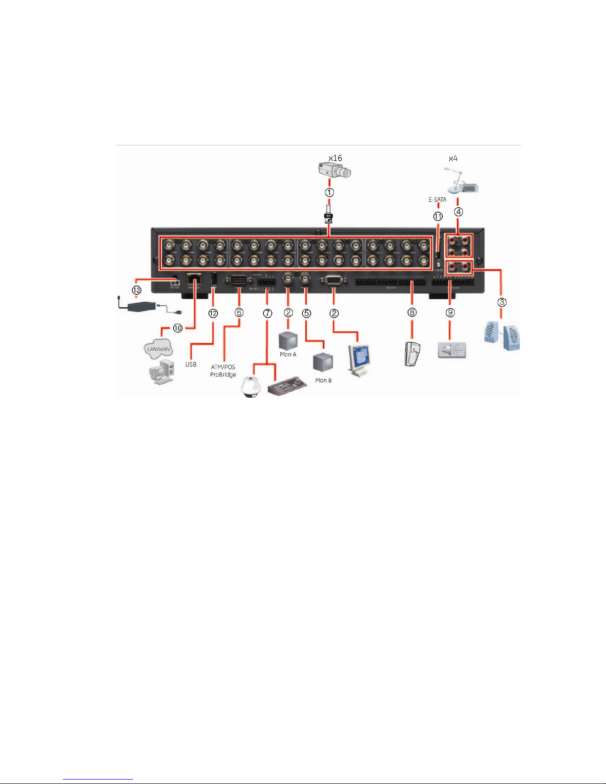
Figure 1 below shows the rear panel connections and describes each connector
on a typical TVR 20 digital video recorder. Details may vary for specific models.
Figure 1: Rear panel connections (16-channel model shown)
Required connections
1. Video inputs: Connect up to 16 cameras to the standard BNC video inputs.
2. Monitor A or VGA monitor (default): Connect the main monitor to one of the output
connections. The VGA monitor must support 800 x 600 Hz resolution.
Optional connections
3. Audio outputs: Connect up to two audio outputs (depends on model) such as line level
devices (for example, speakers with built-in pre-amplifiers).
4. Audio inputs: Connect up to four to audio input (depends on model) such as microphones.
5. Monitor B: Connect a spot monitor (Mon B) to the spot monitor output.
6. RS-232 connector: Connect an RS-232 cable from a device such as a PC to the 9-pin D-sub
input.
7. RS-485/RS-422 connector: For telemetry control or remote control via RS-485 keypads
8. Alarm input: Connect up to 16 dry contacts (depends on model). NO and NC supported.
9. Alarm output: Connect up to four NO/NC alarm output relays (depends on model).
10. LAN: Connect the network devices.
11. e-SATA: Connect the e-SATA for archiving.
12. USB port: Insert USB devices. USB CD/DVD burner and USB HDD are not supported.
Power connection
13. Power socket: Connect the power cord to the TVR 20. Be sure that all devices are
connected and turned on before turning on the unit. Use the external power supply unit
provided.
Page 12

49BChapter 2: Installation
8 TruVision DVR 20 User Manual
Alarm inputs and outputs
Table 2: Number of inputs and outputs
4-channel TVR 20 4 external alarm inputs 1 internal alarm output
8-channel TVR 20 8 external alarm inputs 2 internal alarm outputs
16-channel TVR 20 16 external alarm inputs 4 internal alarm outputs
Alarm inputs
There is a pin connector on the rear panel to connect the alarm inputs. The
number of pins depends on the TVR 20 model. They can be wired normally open
(NO) or normally closed (NC). They are configured in section “Responding to an
alarm” on page 73.
Note: Do not attempt to wire any accessories directly to the I/O connector on the
rear panel. These connections require dry contact (voltage free) closure to
activate.
Figure 2: Programmable alarm inputs
Alarm input with NO in idle state Alarm input with NO in idle state
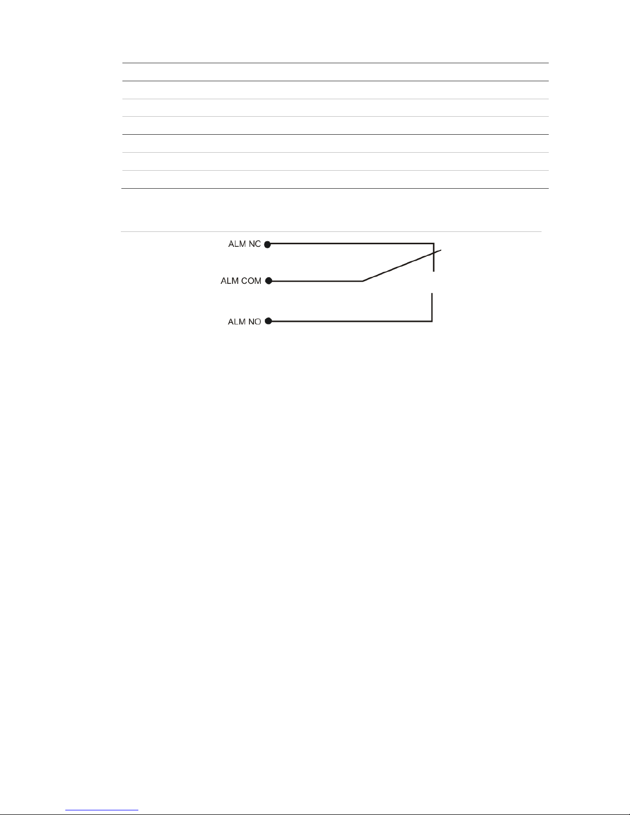
Alarm outputs
The four alarm output relays respond to input alarms and triggers. They can be
configured as NO or NC in section “Alarm and event notification” on page 75.
Table 3: Alarm output pins
Alarm out number Pin Description
Alarm out 1 1 NO (Normally Open)
2 C (Common)
3 NC (Normally Closed)
Alarm out 2 1 NO (Normally Open)
2 C (Common)
3 NC (Normally Closed)
Page 13
49BChapter 2: Installation
TruVision DVR 20 User Manual 9
Alarm out number Pin Description
Alarm out 3 1 NO (Normally Open)
2 C (Common)
3 NC (Normally Closed)
Alarm out 4 1 NO (Normally Open)
2 C (Common)
3 NC (Normally Closed)
Figure 3: Alarm output relay in idle state
Camera inputs
Connect cameras to the TVR 20 using 75-ohm video coaxial cables with BNC
connectors. There are two BNC jacks for each camera. Either jack can receive a
camera signal. The signal is looped (directly connected to the other jack), making
the camera signal available to other equipment.
The camera input connectors are auto terminating. This means that the input
signal will automatically be terminated with 75-Ohms unless a second cable is
connected to the second BNC connector of the same camera input.
Make sure there is 75-Ohm termination at the end of the video line if the signal is
looped through the TVR 20.
RS-485 port
The RS-485 port is used for pan, tilt, zoom control of PTZ cameras as well as for
keypads. See “RS-232 and RS-485 port settings” on page 96 to configure this
port. See Figure 4 on page 10 for the serial pin outs for the configuration.
Page 14
49BChapter 2: Installation
10 TruVision DVR 20 User Manual
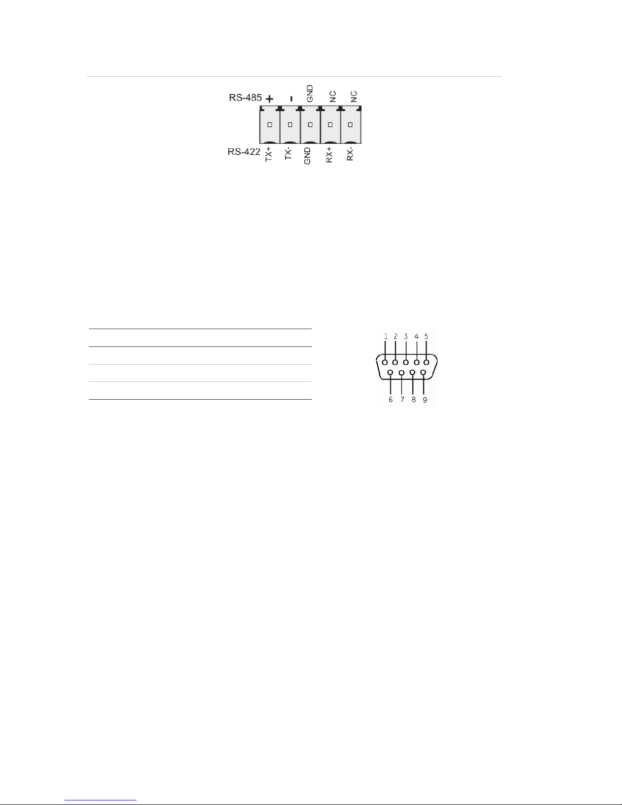
Figure 4: RS-485 pins
RS-232 port
The RS-232 port is provided for use with Interlogix's ProBridge text insertion
interface modules in conjunction with compatible CBR, PB3, POS (point of sale)
and ATM (automated teller machine) systems. See “RS-232 and RS-485 port
settings” on page 96 to configure this port.
Table 4: RS-232 pins
Pin Description
2 TX
3 RX
5 Ground
PTZ dome camera set up
Use the USB mouse provided or the optional KTD-405 keypad for local telemetry
control. If using the TVR 20 over a network, use the web browser to control the
PTZ dome cameras.
The supported protocols are: Interlogix, Pelco-D, and Pelco-P
For information on setting up the PTZ protocols and presets see “PTZ setup” on
page 70 and “RS-232 and RS-485 port settings” on page 96.
Page 15
49BChapter 2: Installation
TruVision DVR 20 User Manual 11
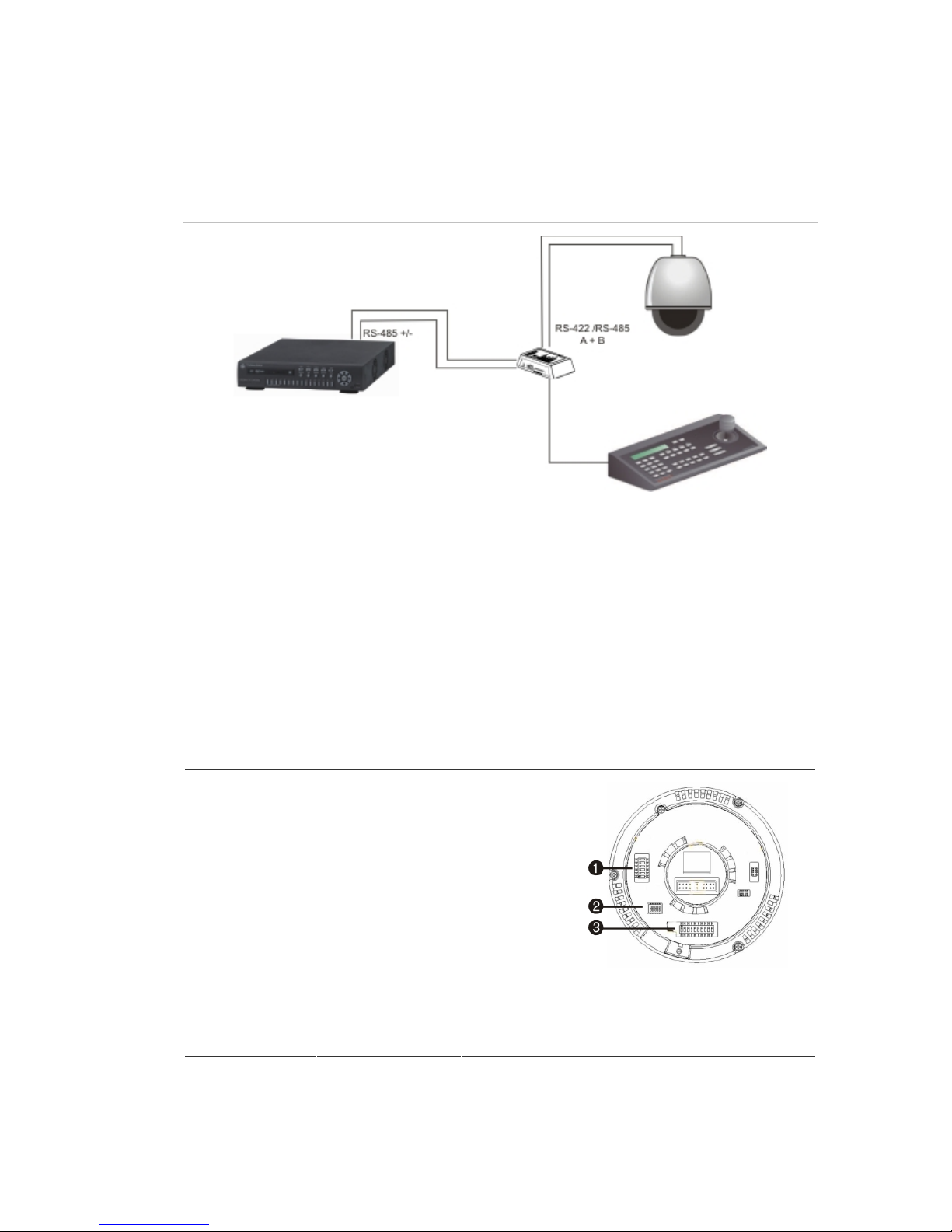
Connecting a TVR 20 to a PTZ dome camera
Use the input/output box that is supplied with the KTD-405 keypad to connect
both a PTZ dome camera and a keypad to the TVR 20. See Figure 5 below.
Figure 5: Connecting a TVR 20 to a PTZ dome camera
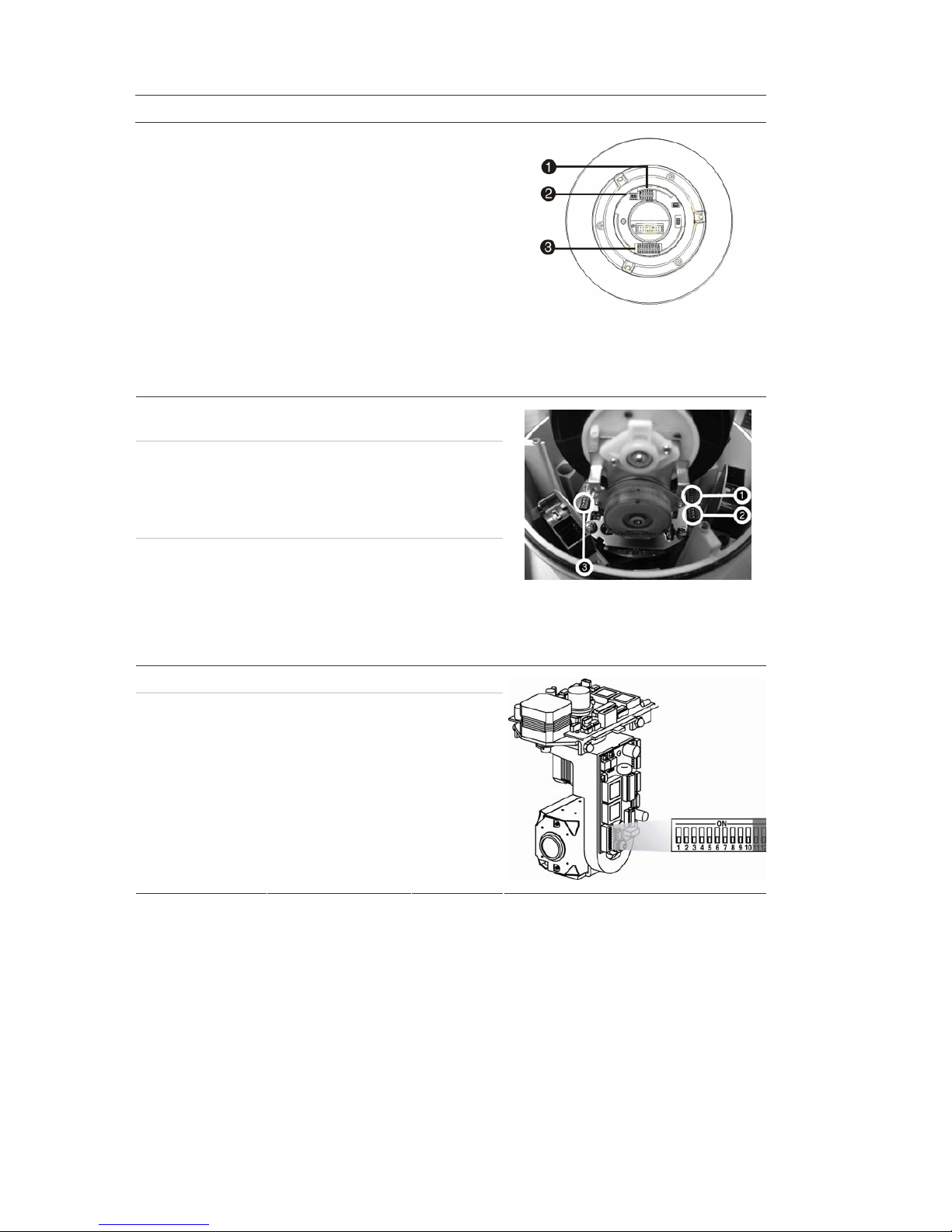
Configuring the PTZ protocols for Interlogix cameras
Before the PTZ cameras are assembled in their housings, set their protocol and
address DIP switches for the TVR 20. See Table 5 below for different Interlogix
PTZ camera settings.
If you are using PTZ cameras from another company, please refer to their
configuration instructions.
Table 5: PTZ protocols for Interlogix cameras
Camera Switch setting
TruVision Mini PTZ
12X: Indoor Dome
Protocol DIP
switches
000000
RS-485
communication DIP
switches
0000000000
Camera site ID DIP
switches
Select the
camera ID
DIP switch
address as
required.
1. Protocol DIP switches;
2. RS-485 communication DIP
switches;
3. Camera site ID DIP switches
Page 16
49BChapter 2: Installation
12 TruVision DVR 20 User Manual
Camera Switch setting
TruVision Mini PTZ
12X: Outdoor
Dome
Protocol DIP
switches
000000
RS-485
communication DIP
switches
0000000000
Camera site ID DIP
switches
Select the
camera ID
DIP switch
address as
required.
1. Protocol DIP switches;
2. RS-485 communication DIP
switches;
3. Camera site ID DIP switches
TruVision Dome
16X PTZ
Protocol switches 0111
Camera site ID
address switches
Select the
camera ID
DIP switch
address as
required.
Baud rate 0000
1. Address switches;
2. Baud switches;
3. Protocol switches
CyberDome Protocol switches NA
Camera site ID
address switches
Select the
camera ID
DIP switch
address as
required.
Page 17

49BChapter 2: Installation
TruVision DVR 20 User Manual 13
Camera Switch setting
CyberDome II Protocol switches 01000
Camera site ID
address switches
Select the
camera ID
DIP switch
address as
required.
1. Protocol switches;
2. Camera site ID address switches
Legend Protocol switches 1
Address switches Select the
camera ID
DIP switch
address as
required.
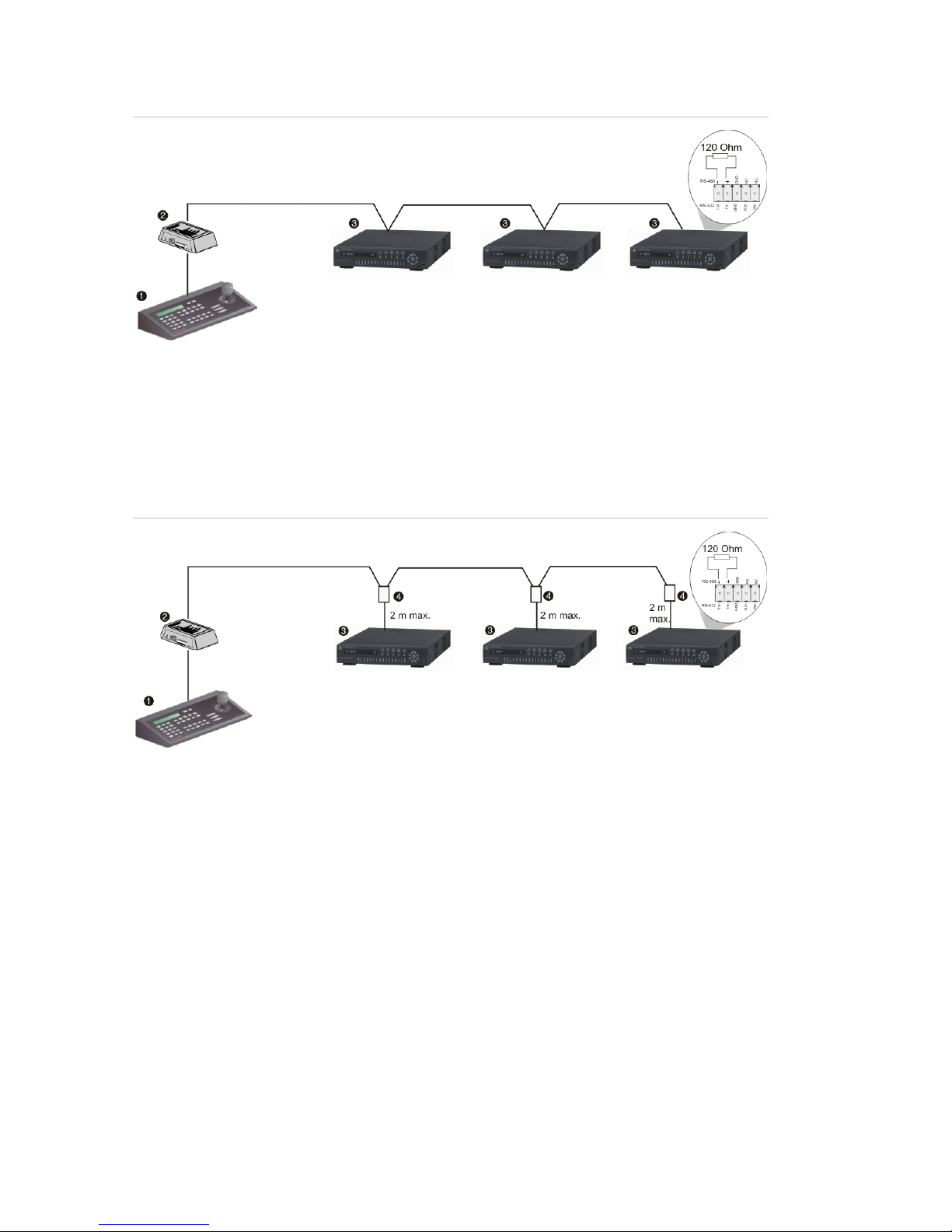
Wiring the KTD-405 keypad
The KTD-405 keypad uses RS-485 simplex wiring. The signal is transferred by a
single twisted pair line. An unshielded CAT5 network cable is recommended for
normal applications. Use a shielded CAT5 cable if the cables could be exposed
to interference.
The maximum number of TVR 20s that can be installed in one bus is 31, with a
maximum cable length of 1200 m. Both can be expanded using a signal
distributor.
Both the first and the last device in series should be terminated with 120 Ohm
resistance to minimize line reflections. See Figure 6 on page 14.
Page 18
49BChapter 2: Installation
14 TruVision DVR 20 User Manual
Figure 6: RS-485 bus serial wiring
1. KTD-405 keypad
2. I/O box
3. TVR 20
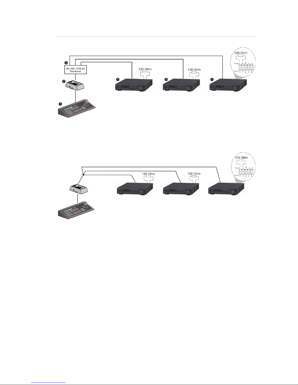
The cable length from box to device cannot exceed 2 m when using connector
boxes. See Figure 7 below.
Figure 7: RS-485 bus serial wiring with connector boxes
1. KTD-405 keypad
2. I/O box
3. TVR 20
4. Connector box
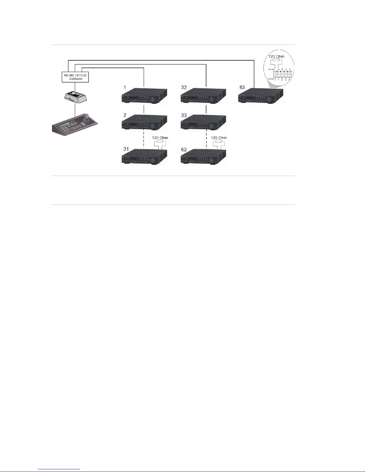
Use an RS-485 signal distributor for a star wiring configuration. See Figure 8 on
page 15.
Page 19
49BChapter 2: Installation
TruVision DVR 20 User Manual 15
Figure 8: Star wiring with RS-485 signal distributor
Correct
1. KTD-405 keypad
2. I/O box
3. TVR 20
4. RS-485/KTD-83 distributor
Incorrect
Use an RS-485/KTD-83 signal distributor to increase the maximum number of
devices on the bus as well as the total range. Each distributor output provides
another RS-485 bus, extending the output an additional 1200 m. Up to 31
TVR 20s can be connected to each output. See Figure 9 on page 16.
Page 20
49BChapter 2: Installation
16 TruVision DVR 20 User Manual
Figure 9: Expanding the system with an RS-485 signal distributor
Caution: Most signal distributors are unidirectional. This means that the signal
only flows from the input towards the outputs. Consequently it is not possible to
connect several keypads.
See “RS-232 and RS-485 port settings” on page 96 to configure the RS-485 port
communication settings.
Using the KTD-405 keypad to address PTZ
cameras in zone mode
The KTD-405 keypad can programmed to operate in zone mode which allows
you to use several DVRs and cameras. A zone is a remote switching device,
such as a DVR, that serves a group of cameras. A system can be divided into as
many as 32 zones, and each zone can have up to 32 cameras depending on the
type of KTD-405 keypad used. See Table 6 on page 17 for the list of PTZ camera
site address values by zone.
To call up a camera in a zone, you must know the zone number and camera
number. See Table 6 on page 17 for the list of receiver site address values by
zone.
Page 21

49BChapter 2: Installation
TruVision DVR 20 User Manual 17
Table 6: PTZ camera site address values by zone
Zone number
Camera
input
1 2 3 4 5 6 7 8 9 10 11 12 13 14 15 16
1 0 32 64 96 128 160 192 224 256 288 320 352 384 416 448 480
2 1 33 65 97 129 161 193 225 257 289 321 353 385 417 449 481
3 2 34 66 98 130 162 194 226 258 290 322 354 386 418 450 482
4 3 35 67 99 131 163 195 227 259 291 323 355 387 419 451 483
5 4 36 68 100 132 164 196 228 260 292 324 356 388 420 452 484
6 5 37 69 101 133 165 197 229 261 293 325 357 389 421 453 485
7 6 38 70 102 134 166 198 230 262 294 326 358 390 422 454 486
8 7 39 71 103 135 167 199 231 263 295 327 359 391 423 455 487
9 8 40 72 104 136 168 200 232 264 296 328 360 392 424 456 488
10 9 41 73 105 137 169 201 233 265 297 329 361 393 425 457 489
11 10 42 74 106 138 170 202 234 266 298 330 362 394 426 458 490
12 11 43 75 107 139 171 203 235 267 299 331 363 395 427 459 491
13 12 44 76 108 140 172 204 236 268 300 332 364 396 428 460 492
14 13 45 77 109 141 173 205 237 269 301 333 365 397 429 461 493
15 14 46 78 110 142 174 206 238 270 302 334 366 398 430 462 494
16 15 47 79 111 143 175 207 238 271 303 335 367 399 431 463 495
17 16 48 80 112 144 176 208 240 272 304 336 368 400 432 464 496
18 17 49 81 113 145 177 209 241 273 305 337 369 401 433 465 497
19 18 50 82 114 146 178 210 242 274 306 338 370 402 434 466 498
20 19 51 83 115 147 179 211 243 275 307 339 371 403 435 467 499
21 20 52 84 116 148 180 212 244 276 308 340 372 404 436 468 500
22 21 53 85 117 149 181 213 245 277 309 341 373 405 437 469 501
23 22 54 86 118 150 182 214 246 278 310 342 374 406 438 470 502
24 23 55 87 119 151 183 215 247 279 311 343 375 407 439 471 503
25 24 56 88 120 152 184 216 248 280 312 344 376 408 440 472 504
26 25 57 89 121 153 185 217 249 281 313 345 377 409 441 473 505
27 26 58 90 122 154 186 218 250 282 314 346 378 410 442 474 506
28 27 59 91 123 155 187 219 251 283 315 347 379 411 443 475 507
29 28 60 92 124 156 188 220 252 284 316 348 380 412 444 476 508
30 29 61 93 125 157 189 221 253 285 317 349 381 413 445 477 509
31 30 62 94 126 158 190 222 254 286 318 350 382 414 446 478 510
32 31 63 95 127 159 191 223 255 287 319 351 383 415 447 479 511
Page 22

49BChapter 2: Installation
18 TruVision DVR 20 User Manual
Monitor connections
Connect the unit to the monitors via 75-ohm video coaxial cables with BNC
connectors. The unit provides a 1 Vpp CVBS signal.
Audio inputs and output
The unit is equipped with four audio inputs and one audio output. Both the audio
output and the audio inputs are line-level. The four audio inputs are associated
with the first four cameras.
Audio input RCA jack, 315 mV, 40k Ohms. Unbalanced
Audio output RCA jack, 315mV, 600 Ohms. Unbalanced
Note: Line-level audio requires amplification.
Page 23
TruVision DVR 20 User Manual 19
Chapter 3
Express setup
The TVR 20 has an express installation wizard that lets you easily configure
basic DVR settings when first used. It configures all cameras simultaneously.
The configuration can then be customized as required. See Chapter 6 “Advanced
setup” on page 61 for more information on customizing the TVR 20.
The TVR 20 can be set up to be either single or dual stream. Dual streaming
allows a sub stream is used for viewing the DVR over the LAN or WAN when the
resolution or frame rate of the recorded video is too high for the available
bandwidth.
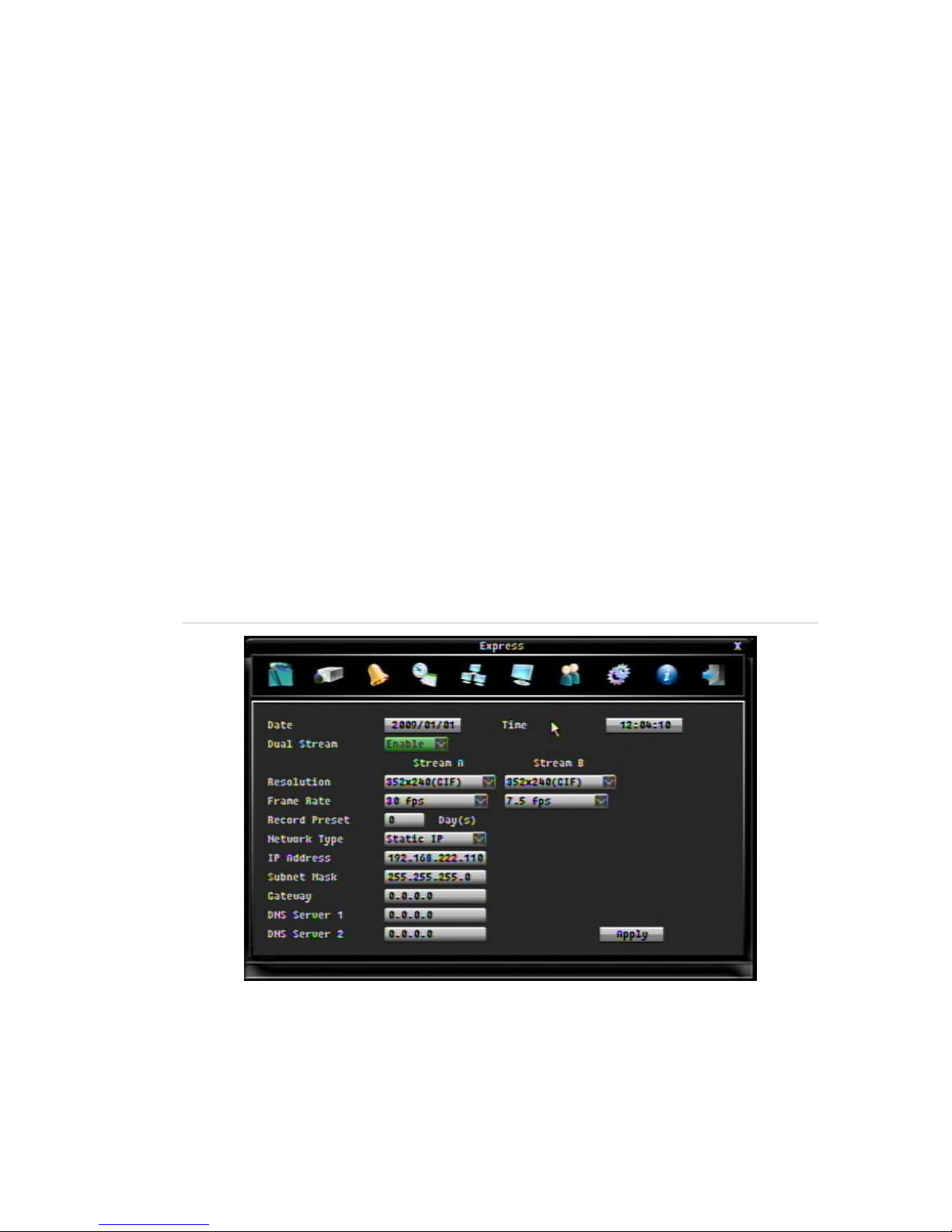
Figure 10: Express menu (Example shown has Dual Stream and Static IP as Network Type
selected)
To quickly setup the TVR 20:
1. In live mode right-click the mouse or press the MENU button on the front
panel. The Menu toolbar appears on-screen.
The Express screen appears by default.
Page 24
50BChapter 3: eZ setup
20 TruVision DVR 20 User Manual
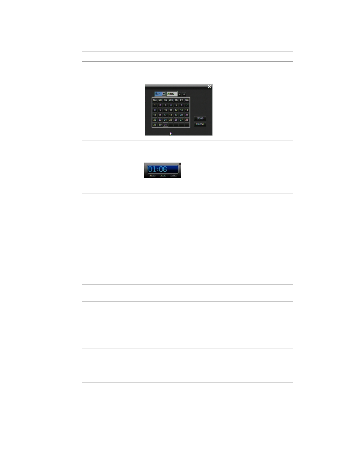
2. Enter the setup values:
Option Description
Date Using the pop-up calendar, enter the current date and click
the Done button.
Time Using the pop-up clock, set the time of the DVR. See the
System menu to change time format.
Dual stream Select dual or single stream.
Resolution Select the recording resolution depending on the video
format.
NTSC: 704 x 480 (4CIF)/ 704 x 240 (2CIF)/ 352 x 240
(CIF) / 176 x 120 (QCIF, B stream only)
PAL: 704 x 576 / 704 x 288 / 352 x 288 / 176 x 144 (QCIF,
B stream only)
Frame rate Set the frame rate. The frame rate values available are:
Full, 25 fps PAL (30 fps NTSC), 20, 16, 12, 10, 8, 6
(default), 4, 2, 1, 1/2, 1/4, 1/8, 1/16. Real time is 25 fps PAL
(30 fps NTSC).
Select a value.
Record preset Select the number of days that the video can be recorded
before being overwritten. Maximum number of days is 60.
Network Type Select one of the three options from the drop-down list.
Static IP: Set a fixed IP for the network.
DHCP: The DHCP server in the LAN will automatically
assign an IP for the network connection.
PPPoE: Set a dynamic IP for the network.
IP Address Specifies the current IP address for the DVR. A Fixed IP
address must be set manually.
If DHCP or PPPoE has been selected, this value will be
assigned automatically.
Subnet Mask Specifies the subnet mask for your network so that the DVR
is recognized within the network.
If DHCP or PPPoE has been selected, this value will be
assigned automatically. Default value is 255.255.255.0.
Page 25
50BChapter 3: eZ setup
TruVision DVR 20 User Manual 21
Option Description
Gateway Specifies the gateway for your network so that the DVR is
recognized within the network.
If DHCP or PPPoE has been selected, this value will be
assigned automatically.
DNS Servers 1/2 Specifies the DNS server for your network so that the DVR
is recognized within the network.
If DHCP or PPPoE has been selected, this value will be
assigned automatically.
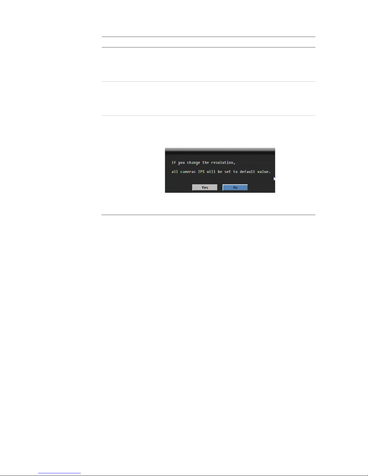
Apply Click to save and apply the Express settings to the DVR.
The DVR will automatically adjust the recording frame rate
depending on the settings selected. This screen will pop up:
Click Yes to change the resolution, recording frame rate,
and quality for the settings selected.
Page 26

50BChapter 3: eZ setup
22 TruVision DVR 20 User Manual
Page 27

TruVision DVR 20 User Manual 23
Chapter 4
Operating instructions
Control interfaces
The TVR 20 has three control interfaces:
• Built-in interface
• Display interface
• Web browser interface
Built-in interface. The built-in interface is displayed on the monitor output. It
consists of a main menu and several dialog screens that let you configure and
control the device. You can invoke the built-in interface using the front panel,
remote control, or mouse.
Display interface. The display interface consists of various toolboxes that
appear on top of the monitor image. These let you control live or playback video
while in PTZ or playback mode. You can invoke the display interface from the
built-in interface screens or from the mouse menu. The controls in any toolbox
can be operated using the front panel, remote control, and mouse.
Web browser. The Web browser interface uses Internet Explorer to simulate the
display and control functions of the monitor on a remote PC. The Web browser
interface can only be invoked by a PC with Internet access. See Chapter 7 “Web
browser” on page 103.
Controlling the TVR 20
There are several ways to control the TVR 20:
• Front panel control
• IR remote control
• Mouse control
Page 28
51BChapter 4: Operating instructions
24 TruVision DVR 20 User Manual
• KTD-405/KTD-405-2D keypad control
• Web browser control
You can use your preferred control method for any procedure, but in most cases
we describe procedures using mouse terminology. Optional control methods are
given only when they differ substantially from mouse control methods.
Using the front panel
The buttons on the front panel control can be used to operate many, but not all,
of the main functions of the TVR 20 of the DVR functions. The LED indicators
light up or flash to alert you of various conditions. The functions available can be
limited by setting passwords. See Table 7 below for more information.
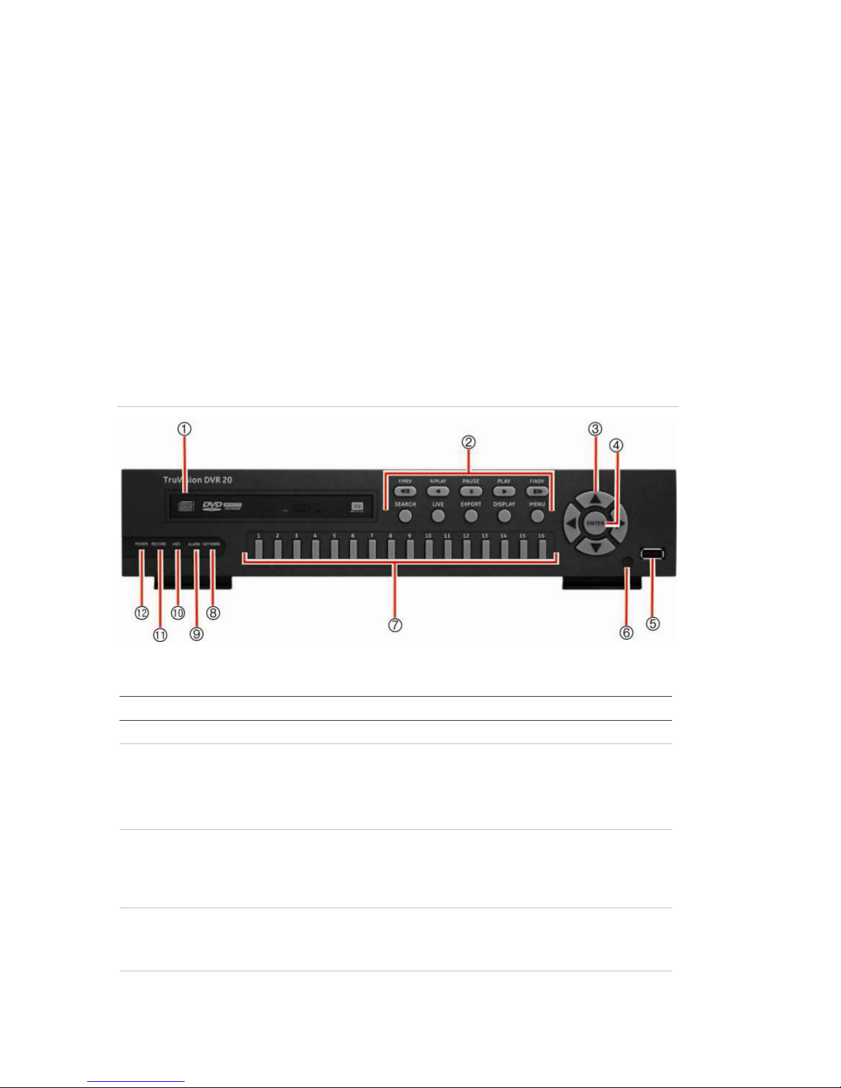
Figure 11: Front panel
Table 7: Front panel legend
Item Name Description
1. DVD+RW DVD+RW drive to export video data for archiving.
2. Function buttons Use to operate the main functions of the TVR 20. However, they
have limited functionality compared to the mouse. Many also
have dual functionality depending on for how long they are
pressed. See Table 8 on page 25 for information on how to use
them.
3. Arrow buttons Use to navigate menus when in main menu. Use the Left or Right
A
rrow keys to navigate through fields. Use the Up or Down Arrow
keys to change the value of a selected field.
When in zoom mode, use the arrow buttons as directional keys.
4. ENTER button Use to select menus when main menu. Press ENTER to confirm
menu selection (press MENU to return to previous menu).
See Table 8 on page 25 for further information.
5. USB port USB-2.0 port to connect a USB device.
Page 29

51BChapter 4: Operating instructions
TruVision DVR 20 User Manual 25
Item Name Description
6. IR receiver This is the receiver for the remote control.
7. Cameras 1-16
buttons
Selects the channel for full screen display. There are 1 to 16 / 1
to 8 keys depending on the DVR model. The LED indicates which
channel is active.
8. Network LED Green: Network working correctly.
Red: Fault.
9. Alarm LED Green: No external alarm.
Red: Indicates an external alarm status.
10. HDD LED Green (flashing): Hard drive is working correctly.
Red: Fault
11. Record LED Green: Recording correctly.
Red: Fault
12. Power LED Green: LED indicates that the DVR is working.
No light: Indicates the DVR is powered down.
Using the front panel buttons
Table 8: Front panel button actions
Live mode Playback mode PTZ mode
Button Press button Press button and
hold for more
than 1 second
Press button Press button
F/REV No action No action Fast reverse
playback video
from current time.
No action
R/PLAY Reverse playback
video from current
time.
No action Reverse playback
video from current
time.
No action
PAUSE No action No action Pause playback of
video.
No action
PLAY Playback video
from preprogrammed time
(see page 97) or
from lates
t
recording found.
No action Playback video at
normal speed.
Zoom out
F/ADV No action No action Fast forward video. Zoom in
SEARCH Press once: Enter
Search menu.
Press twice: Enter
Advanced Search
menu.
No action Press once: Enter
Search menu.
Press twice: Enter
Advanced Search
menu.
No action
Page 30

51BChapter 4: Operating instructions
26 TruVision DVR 20 User Manual
Live mode Playback mode PTZ mode
Button Press button Press button and
hold for more
than 1 second
Press button Press button
LIVE View a sequence
of images from
several cameras
on the main
monitor.
View a sequence
of images from
several cameras
on the spot
monitor.
Enter Live mode.
No action
EXPORT Enter Quick
Archive menu.
Switch between
VGA and BNC as
main monitor.
Press once: Enter
Archiving menu.
Press twice: Begin
archiving
Preset and channel
number to save PTZ
preset.
DISPLAY Change display
modes on main
monitor.
Change between
main and spot
monitors.
Change display
modes on main
monitor.
Preset and channel
number to activate
PTZ preset.
MENU Main menu
appears on main
monitor. Press
again to return to
live mode.
Exit digital zoom
mode.
No action Return to Search
menu.
Exit PTZ mode and
return to live mode.
Arrows Full screen view:
No action.
Multiscreen view:
Cameo selector
moves on main
monitor.
No action Full screen view:
No action.
Multiscreen view:
Cameo selector
moves on main
monitor.
Pan and tilt
functions.
ENTER Toggle audio
on/off.
In main menu
press to confirm
menu selection.
Enter PTZ mode. Toggle audio on/off. Confirm preset
entries.
Camera
buttons
Press once:
Switch between
cameras on main
monitor.
Press twice: Enter
digital zoom
mode.
Switch between
cameras on spot
monitor.
Switch between
cameras on main
monitor.
Switch between
cameras.
Using the mouse
The USB mouse provided with the TVR 20 can be used to operate all the
functions of the DVR, unlike the front panel which has limited functionality. The
Page 31

51BChapter 4: Operating instructions
TruVision DVR 20 User Manual 27
USB mouse lets you navigate and make changes to settings in the user
interface.
Connect the mouse to the TVR 20 by plugging the mouse USB connector into
the USB port on the front panel. The mouse is immediately operational and the
pointer should appear. The recommended mouse types are Logitech® and
Microsoft® wired USB wheel-mouse. The DVR does not support the wireless
USB mouse.
Move the pointer to a command, option, or button on a screen. Left-click the
mouse to confirm a selection.
To use the mouse in live mode:
1. Scroll forward and backward between cameras.
When in multiscreen mode, use the scroll button on the mouse to scroll
forward and backward through the cameras.
2. Double-click to toggle between full-screen and multiview.
When in multiview, double-click a camera to display its image in full-screen
view. Double-click again to return to multiview.
Using the remote control
The TVR 20 is supplied with an infra red (IR) remote control unit. Like the mouse,
it can be used to operate all of the main functions of the TVR 20.
The remote control can be programmed with a unique address so that the
controller will only be able to communicate with DVRs with that address. No
programming is necessary if using a single TVR 20. See “Audio, remote control,
language settings and playback replay time” on page 97 for information on
setting up the remote control ID so that the DVR recognizes it.
Page 32

51BChapter 4: Operating instructions
28 TruVision DVR 20 User Manual
Figure 12: Controls on the IR remote control
1. HD button: For future use.
2. Alarm button: Acknowledge an alarm.
3. Live button: Switch to live mode.
4. Display button: Toggle between the
multiview screens.
5. Sequence button: Start and stop
sequencing.
6. Main & spot monitors: Toggle between
the main and spot monitors.
7. Device button: If there is more than one
TVR 20, select the device to control.
8. Search button: Open the Advanced
Search menu.
9. Menu button: Access the main menu
10. Replay button: Replay the selected file
from the beginning.
11. ESC button: Go back one step.
12. Arrow buttons: Use to select a command,
option, or button on a screen.
13. Enter button: Use to confirm a selection.
14. PTZ button: Start PTZ operation on the
selected camera.
15. Lens control buttons: Control the zoom,
iris, and focus of a camera.
16. Numeric buttons: Select a camera, and
enter numbers.
17. Archive: Open the Quick Archive menu.
18. Playback buttons: Control playback.
To place batteries into the remote control:
1. Remove the battery cover.
2. Insert the batteries. Make sure that the positive (+) and negative (−) poles are
correctly placed.
3. Replace the battery cover.
To connect the remote control to the TVR 20:
1. Turn on the TVR 20 and wait for the live video to appear.
2. On the remote control, press the DVR button for the required TVR 20 device.
The remote control is now operational.
Page 33

51BChapter 4: Operating instructions
TruVision DVR 20 User Manual 29
Note: If there is only one TVR 20 used, the default DVR button is 1. If more
than one TVR 20 is used, they must each be first allocated an ID for remote
control. See “Audio, remote control, language settings and playback replay
time” on page 97 for more information.
Troubleshooting the remote control:
If the remote control is not functioning properly, perform the following tests:
• Check the battery polarity.
• Check the remaining charge in the batteries.
• Check that the remote control sensor is not masked.
If the problem still exists, please contact your administrator.
Using a KTD-405/KTD-405-2D keypad
Use the keypad to carry out functions similar to the front panel buttons. We use
the KTD-405/KTD-405-2D keypad controller (Figure 2) in this manual. For
detailed keypad instructions, refer to the KTD-405/KTD-405-2D Controller
Keypad User Manual.
Setting up a KTD-405 keypad to work with the TVR 20
To set up a KTD-405 keypad to work with the TVR 20:
1. Press and hold the set key of the keypad until Enter programming code
displays.
2. At the code entry display, enter the programming code 9, 5, 1. Then press the
seq button.
3. At the first menu display, press 1 to select the option Switcher/ MPLX.
4. At the Switcher/MPLX screen, press 2 to select the option Calibur.
5. At the Enter Calibur Address screen, enter the bus address of the TVR 20.
See the section “RS-232 and RS-485 port settings” on page 96 for
information on the bus address of your TVR 20.
To access the PTZ camera’s programming menus using a KTD-405 keypad:
1. Switch the keypad to the camera you want to program.
2. Press and hold the set key until Enter programming code displays.
3. At the code entry display, enter the programming code 9, 5, 1. Then press the
seq button.
4. At the first menu display, press 3 to select the option Camera.
Page 34

51BChapter 4: Operating instructions
30 TruVision DVR 20 User Manual
5. At the Enter camera number screen, enter the site number of the PTZ camera
you wish to program. Camera default value is 1. The Main Page 1 menu
appears.
For further information on programming a PTZ camera, please refer to the PTZ
camera user manual.
Navigating the menus with the KTD-405 keypad
You can use the keypad joystick and keys to navigate through the menu system.
See Figure 13 below and Figure 14 on page 31 for further information on their
use.
Figure 13: Menu keys of the KTD-405/405-2D keypad
Note: Shaded keys appear on the KTD-405A/ KTD-405-2DA only
Table 9: Navigating the programming menus using the KTD-405/405-2D keypad
Key Function
Scroll up the menus.
Scroll down the menus.
Scroll left or right in the menu.
Enter or exits a menu or submenu.
Iris +: Enter or selects a menu option
Iris -: Exit a menu option. There is no need to select the menu option Exit to quit
a menu.
Page 35

51BChapter 4: Operating instructions
TruVision DVR 20 User Manual 31
Figure 14: Joystick motion
Scroll up
Previous
Next
Scroll down Edit (turn joystick clockwise)
Screen overview
Each setup menu screen includes various options and buttons. The screen is
divided into three main sections (Figure 15 below) as shown below;
Figure 15: Setup menu (Camera setup menu shown)
1. Menu toolbar: Setup options available for the selected menu function. Move the mouse over
an icon and click to select it. See page 61 for a description of the icons.
2. Submenus
: Submenus for the selected menu function are displayed. Click on an item to
select it.
3. Setup menu: All the details for the selected sub-menu will be available. Click on a field to
make changes.
Navigating through a dialog screen
Use the mouse to select any option or button on the screen. You can also use
the directional arrow buttons (Up, Down, Left, or Right) on the front panel to
navigate through the options and press ENTER to select. Press MENU to return
to configuration category and icon.
Page 36

51BChapter 4: Operating instructions
32 TruVision DVR 20 User Manual
Changes to screen settings can be entered in various ways as shown in Table 10
below.
Table 10: Types of control
Control Function Description
Edit box
A
n edit box lets you type characters to set the
value of an option, such as a camera name.
You must be in edit mode before you can
enter a value.
Click the box and an on-screen keyboard will
appear to enter text. See “Using the onsc
reen keyboard” below.
List box Provides more than two values for the option.
Only one of them can be selected. Click the
scroll arrows at the right-hand side of the box
to scroll through the possible values. Click an
option to then select it.
Check box Provides two values: indicates enabled and
× indicates disabled. Click the check box.
Button Executes the function displayed on the
button. Click the button.
Bar Lets you adjust the scale of a value. Click
and hold the cursor. Adjust its position left or
right along the bar.
Using the on-screen keyboard
A keyboard will appear on-screen when you need to enter characters in a screen
option. Click a key to input that character. Inactive keys are white.
Figure 16: On-screen keyboard
The keys on the right and bottom have the following functions:
Page 37

51BChapter 4: Operating instructions
TruVision DVR 20 User Manual 33
Table 11: Description of the keys in the on-screen keyboard
Key Description
Esc Cancel action and exit the on-screen keyboard
Del Delete the character in front.
Bs Backspace. Delete the character entered
OK Confirm the selection and exit the on-screen keyboard
Cap Enter a capital letter
Space Enter a space
Move the cursor to the left
Move the cursor to the right
Page 38

51BChapter 4: Operating instructions
34 TruVision DVR 20 User Manual
Page 39

TruVision DVR 20 User Manual 35
Chapter 5
Basic operation
Turning on the TVR 20
Before turning the TVR 20 power on, make sure that the power supply matches
that of the TVR 20 and the AC adapter is connected correctly. Connect at least
one monitor to the video out or the VGA interface. Otherwise, you will not be able
to see the user interface and operate the device.
The TVR 20 auto-detects the video mode (PAL or NTSC) on startup.
To turn on the TVR 20:
1. Connect power supply correctly.
Once the TVR 20 is powered, the Power LED on the front panel should light
up in green.
Logging on
Use passwords to limit access to the TVR 20. Only authorized users should be
able to modify menu settings or carry out certain tasks.
The TVR 20 is shipped with one predefined user for the system administrator.
The default system administrator log on uses “admin” as a user name with a
default password of 1234. You can modify the admin password but not the admin
user name. We recommend that you change the admin password once you have
completed the installation and setup in order to protect against unauthorized
access. The administrator can create up to nine users and define their privileges.
For more information, see “Managing users” on page 92.
Page 40

52BChapter 5: Basic operation
36 TruVision DVR 20 User Manual
Figure 17: Login screen
To log on to the TVR 20 main menu:
1. In live mode right-click the mouse or press the MENU button on the front
panel. The Login screen appears.
2. In the User Name box, select the default user name “admin” (lower case).
3. In the Password edit box, enter the default password of 1234 using the onscreen keyboard that appears.
Note: The password is always entered using the on-screen keyboard
regardless of the input device used (mouse, front panel, keypad, remote
control).
4. Click Login to enter the main menu.
Note: It is strongly recommended that you change the password of the
administrator. Do not leave 1234 as the default password. See “Changing a user
password” on page 93 for information on changing a password.
Note: You will hear an audible warning when an incorrect user name or
password is entered. After three incorrect entries, the unit returns to live mode.
TVR 20 toolbar overview
In live mode (see “Live mode” on page 37) you can quickly access several
frequently used functions that allow you to control what you see on-screen by
using the Main toolbar. See Figure 18 below.
As you move the mouse over the icons displayed in the toolbar, the title of each
icon will be displayed below.
Note: The eZ menu screen always appears by default under the Main toolbar.
Page 41

52BChapter 5: Basic operation
TruVision DVR 20 User Manual 37
Figure 18: Main toolbar
Table 12: Description of the icons in the main toolbar
Key Description Key Description
1.
Monitor: Switch control between
the main and spot monitors.
8.
Pause: Pause live mode of the
selected camera.
2.
Main Menu: Access the Menu
toolbar to customize the TVR 20
setup.
9.
Playback: Playback recorded
video.
3.
Switch Channel: Switch channel
selection between cameras.
10.
Archive: Archive recorded video.
4.
Layout: View multiscreen displays.
11.
Log: Display list of status and
configuration changes as well as
logins carried out.
5.
Sequence: View a sequence of
live camera pictures of several
cameras. Each camera has a preprogrammed dwell time.
12.
Alarm: Manually acknowledge
alarm.
6.
PTZ: Move the camera to the
desired position.
13.
Close: Close the Main toolbar.
7.
Search: Search for a recorded
video.
To access the Main toolbar from live mode:
1. Right-click the mouse, or press the MENU button on the front panel. The Main
toolbar appears.
To close the main menu:
Click the “X” on the top right of the Main toolbar, or press the MENU button on
the front panel.
Live mode
Live mode is the normal operating mode of the unit where you watch live pictures
from the cameras. The TVR 20 automatically enters into live mode once powered
up. On the display screen, you can see the current date and time, hard drive
capacity, and camera name. To change the information displayed on-screen, see
“Information displayed on screen” on page 89.
Page 42

52BChapter 5: Basic operation
38 TruVision DVR 20 User Manual
TVR 20 has camera autodetection mode so does not record from a channel if no
camera is connected to it.
Note: Every time you logout from the main menu you will be required to log on
again to access the system.
Displaying status information
Information about the camera and system status is displayed on-screen as icons
on the main monitor. The camera status icons are shown for each camera, and
the system status icons are shown along the bottom of the screen.
Each icon represents information on a specific item. Many can be set up to
appear on screen. The Audio Out icon only appears when the option is manually
selected by the user (see “Selecting audio” on page 40.) The Motion, Event and
Alarm icons appear both as part of the camera status information as well as part
of the system status information.
Four system status icons will trigger an alarm message: HD failure, Fan failure,
HD temperature too high, and No network. See Table 19 on page 76 for a
description and Chapter 9 “Troubleshooting” on page 113 for information on how
to handle these alarms.
See Figure 19 below for a description of all the icons.
Figure 19: Status icons
Camera status information:
Appears automatically on-screen:
Recording
Video loss
Only appears on-screen when set up in the Display menu:
Playback Fast forward Fast
backward
Back Express copy
Pause
Alarm Event Motion
Only appears on-screen when manually selected:
Audio out
Page 43

52BChapter 5: Basic operation
TruVision DVR 20 User Manual 39
System status information:
Appears automatically on-screen:
Fan failure HD failure HD temperature too
high
No network
Only appears on-screen when set up in the Display menu:
Monitor A
selected
Monitor B
selected
New firmware Sequence Alarm
Audio in Motion Event
Selecting the camera display
To select the camera displayed:
Mouse
1. In live mode right-click the mouse to display the Main toolbar.
2. Click the Switch Channel icon. The camera number toolbar appears (16channel DVR shown).
3. Click the camera number desired. The selected camera display appears.
Front panel
In live mode press a numeric button on the front panel to switch to the
corresponding camera display. For example, press button 2 to view camera 2 in
full screen mode. The Main toolbar must be closed.
Viewing in multiscreen
The 16-channel TVR 20 has seven multiscreen display formats available as well
as full screen. The eight-channel TVR 20 has six multiscreen display formats.
A cameo is any cell in a multiscreen display. A camera picture can only be shown
in one cameo at a time. To change the order of cameras in the cameos, see
“Switching cameras” on page 41.
To change the multiscreen format:
Note: You cannot scroll between the multiscreen formats if you are in digital
zoom mode (the word Zoom appears on the top of the screen.) Press MENU to
exit digital zoom mode and return to live mode.
Page 44

52BChapter 5: Basic operation
40 TruVision DVR 20 User Manual
Mouse
1. In live mode right-click the mouse or move the cursor to the bottom of the
screen. The Main toolbar appears.
2. Click the Layout icon. The monitor layout bar appears showing the display
options available.
3. Click the desired display option.
Front panel
1. In live mode press the DISPLAY button to scroll between the different layout
options available.
To change between multiscreen and full-screen display:
1. In live mode double left-click the mouse on a camera cameo. The full-screen
display of that camera appears. Double left-click the mouse again to return to
multiscreen format.
Note: The Main toolbar must be closed.
Selecting audio
You can hear audio from a specified camera in both live and playback mode.
Only audio for the selected camera is heard. However, in order to be able to hear
audio in playback you must select the Record Audio option for a camera in the
Camera menu (see “Basic camera setup” on page 64 for more information.)
Table 13: Number of audio channels available
DVR version Number of audio channels
4-channel (2 audio in and 1 audio out) 1
8-channel (2 audio in and 2 audio out) 2
16-channel (4 audio in and 2 audio out) 4
To activate/deactivate audio:
1. In live mode select a camera display.
2. Press the ENTER button on the front panel to activate audio. The Audio In
status icon
appears on the camera display.
3. Press the ENTER button again to deactivate audio for the specified camera.
Page 45

52BChapter 5: Basic operation
TruVision DVR 20 User Manual 41
Selecting a monitor
The TVR 20 can be connected to up to three monitors; two main monitors (VGA
and BNC) and one spot monitor (BNC). However, only one monitor can be
controlled at a time. If both VGA and BNC monitors are connected, the VGA
monitor is the default main monitor. Use the “Display settings” on page 89 to set
up the format of the main monitor.
To switch between the main and spot monitors:
On the front panel press the DISPLAY button for a few moments to change from
the main to the spot monitor. Continue to press the DISPLAY button for a few
moments to scroll between the different multiscreen options on the spot monitor.
Press the DISPLAY button quickly to change back to the main monitor.
The monitor status icon will appear on the main monitor screen indicating which
monitor is active.
Monitor A (main) is selected
Monitor B (spot) is selected
Switching cameras
You can switch the channel of a camera with that of another camera in the
system. This lets you, for example, have the images of camera 1 appear on
channel 10, and the images of camera 10 appear on channel 1. This feature is
useful when you want to watch the images from specific cameras next to each
other on-screen.
To assign a camera to a different channel using the mouse:
1. In live mode select a camera by clicking its cameo in a multiscreen display.
2. Right-click the mouse or move the cursor to the bottom of the screen. The
Main toolbar appears.
3. Click the Switch Channel icon. The Switch Channel bar appears on-screen.
The channel for the selected camera is highlighted.
4. Click a different channel number for the camera. The switch automatically
occurs.
To assign a camera to a different channel using the front panel:
1. In live mode select a camera by clicking its cameo in a multiscreen display.
2. Push and hold the camera button that you want to switch.
The two cameos switch positions on-screen.
Page 46

52BChapter 5: Basic operation
42 TruVision DVR 20 User Manual
Sequencing live mode
The sequencing feature allows a camera to be displayed briefly on-screen before
advancing to the next camera in the sequence list. Sequencing can only be done
in full screen mode.
Each camera on the main and spot monitors can have a pre-programmed dwell
time and sequence order. See “Sequencing main and spot monitors” on page 91
for the setup information. The default sequence list displays each camera in
numerical order.
Sequencing live mode using the mouse:
1. Select the camera where you want to start sequencing.
2. Right-click the mouse. The Main toolbar appears on-screen.
3. Click the Sequence icon. The sequencing starts.
4. Press the icon again to stop the sequencing.
Sequencing live mode using the front panel:
1. Select the camera where you want to start sequencing.
2. Press the LIVE button on the front panel. The sequencing starts.
3. Press the LIVE button again to stop the sequencing.
Digital zoom
You can easily zoom in or out of a camera image using the digital zoom function.
The zoom function doubles the size of the camera image. This function is only
available from the front panel.
Note: You must be in live mode.
To quickly zoom in/out on a camera image:
1. Select the camera you wish to use.
Note: The Main toolbar must be closed.
2. Press the camera number button twice on the front panel for the selected
camera. The word “Zoom” appears on-screen.
3. Using the arrow buttons move the camera image around on-screen.
4. To exit digital zoom, press the MENU button and return to live mode.
Controlling a PTZ camera
The PTZ control interface lets you control the PTZ operation of the cameras
within the TVR 20 user interface. You can control PTZ cameras using the buttons
on the front panel, the KTD-405 keypad, and remote control as well as using the
Page 47

52BChapter 5: Basic operation
TruVision DVR 20 User Manual 43
PTZ toolbar accessed with the mouse. Access to PTZ functions may require a
password.
Accessing PTZ mode using the mouse
In live mode right-click the mouse to display the Main toolbar. Click the PTZ icon
to display the PTZ menu directly. The PTZ toolbar appears (see Figure 20
below.) If you were in multiscreen mode, the screen changes to full screen.
Figure 20: PTZ toolbar
Table 14: Description of the PTZ toolbar
Key Function Description
1. Direction arrow
buttons
Use the arrow buttons to move the PTZ camera to the
desired position.
2. Zoom Use to zoom in or out. Click Z+ to zoom in, and Z- to zoom out.
3. Focus Use to focus in or out. Click F+ to focus in, and F- to focus out.
4. Iris Use to adjust the mount of light. Click I+ to increase light level,
and I- to decrease the light level.
5. Preset Use to enter Preset values. An numeric keypad automatically
appears on-screen to enter the value.
6. Tour Use to enter Shadow Tour values. A numeric keypad
automatically appears on-screen to enter the value.
7. Save Save all changes made.
8. Exit Quit PTZ mode.
Accessing PTZ mode using the front panel
To enter PTZ mode press and continue to hold the ENTER button on the front
panel when in live mode. The PTZ Help pop-up appears on-screen. It shows the
front panel buttons to press to control PTZ. If you were in multiscreen mode
initially, the screen changes to full screen.
Page 48

52BChapter 5: Basic operation
44 TruVision DVR 20 User Manual
Figure 21: PTZ Help pop-up using the front panel
PTZ HELP
Move PTZ -> Arrows
Zoom in & out -> Fast forward/Play
Go to preset -> Export
Hide Help -> Display
PTZ Esc -> Menu
Using preset positions
A preset point is a four-digit number represents the camera’s position, zoom,
focus, and iris. You can save up to 255 preset points.
Note: You must be in live mode.
To call up a preset position using the mouse:
1. Select a camera on-screen.
2. Right-click the mouse. The Main toolbar appears on-screen. If requested,
enter a user name and password in the Login screen.
3. Click the PTZ icon. The PTZ toolbar appears on-screen.
4. Click the Preset button. A virtual keyboard appears on-screen.
5. Enter a Preset number. The number is displayed in the keyboard window.
Correct the entry by pressing the Preset icon on the PTZ toolbar.
6. Click the Go button. The selected camera moves to the position of that preset
number.
7. When finished, click the “X” on the top right of the menu to quit PTZ mode
and return to live mode.
To call up a preset position using the front panel:
1. Select a camera on-screen.
2. Press and hold the ENTER key. The PTZ Help pop-up screen appears. If
requested, enter a user name and password in the Login screen.
3. Press the EXPORT button to enter a preset number. A virtual keyboard
appears on-screen.
4. Enter a Preset number. The number is displayed in the keyboard window.
Correct the entry by pressing the EXPORT button again and re-enter the
preset number.
5. Click the Go button. The selected camera moves to the position of that preset
number.
6. When finished, press MENU to quit PTZ mode and return to live mode.
Page 49

52BChapter 5: Basic operation
TruVision DVR 20 User Manual 45
To program a preset position using the mouse:
1. Select a camera on-screen.
2. Right-click the mouse. The Main toolbar appears on-screen.
3. Click the PTZ icon. If requested, select a user name and enter the password
in the Login screen. The PTZ toolbar appears on-screen.
4. Click the Preset button. A virtual keyboard appears on-screen.
5. Enter the numbers of the new preset position. The number appears in the top
of the keyboard. Up to four digits can be entered. Correct the entry by
pressing the Preset icon on the PTZ toolbar.
6. Click the Set button on the virtual keyboard to set the preset ID.
7. In the PTZ toolbar click the Save icon to save all changes.
8. When finished, press MENU to quit PTZ mode and return to live mode.
To program a preset position using the front panel:
1. Select a camera on-screen.
2. Press and hold the ENTER key. The PTZ Help pop-up screen appears. If
requested, select a user name and enter the password in the Login screen.
3. Press the EXPORT button. A virtual keyboard appears on-screen.
4. Enter a Preset number. The number is displayed in the keyboard window.
Correct the entry by pressing the EXPORT button again and re-enter the
preset number.
5. Click the Set button on the virtual keyboard to set the preset ID.
6. When finished, press MENU to quit PTZ mode and return to live mode.
Using shadow tours
A shadow tour allows a preprogrammed motion of the camera.
Note: You must be in live mode.
Page 50

52BChapter 5: Basic operation
46 TruVision DVR 20 User Manual
To program a shadow tour using the mouse:
1. Select a camera on-screen.
2. Right-click the mouse. The Main toolbar appears on-screen.
3. Click the PTZ icon. If requested, select a user name and enter the password
in the Login screen. The PTZ toolbar appears on-screen.
4. In the PTZ toolbar use the arrow keys to move the PTZ camera along the
desired track.
5. Click the Tour button. A virtual keyboard appears on-screen.
6. Enter the numbers of the new shadow tour track. The number appears in the
top of the keyboard. Up to four digits can be entered. Correct the entry by
pressing the Tour icon on the PTZ toolbar.
7. Click the Set button on the virtual keyboard to save the shadow tour ID.
8. In the PTZ toolbar click the Save icon to save all changes.
To run a shadow tour using the mouse:
1. In the PTZ toolbar click the Tour button. A virtual keyboard appears onscreen.
2. Select the numbers of the desired shadow tour position. The number is
displayed in the keyboard window.
3. Click the Go button. The camera moves in the shadow tour.
Playing back recorded video
The TVR 20 lets you to quickly locate and playback recorded video. There are
several ways to playback video:
Instant playback of recorded video.
Search the video archives by specific time, date, event, or bookmarks. See
“Searching and playing back recorded video” on page 53.
The DVR continues to record the live mode from a camera while simultaneously
playing back video on that camera display. Access to playback functions may
require a password.
You can playback more than one camera at a time. However, all multiscreen
cameras in playback play simultaneously. This means, for example, that it is
easy to follow the path of an intruder who has passed in front of several cameras.
You must be in live mode to playback video.
It is easy to select the start and end playback times using the playback toolbar.
See Figure 22 on page 47.
Page 51

52BChapter 5: Basic operation
TruVision DVR 20 User Manual 47
Figure 22: Playback toolbar
Table 15: Description of playback toolbar
Item Description
1. Zoom level: Zoom in or out of the time line to extend the period of time. There are
five time levels ranging from one hour to one week:
L1: Jump back up to one hour
L2: Jump back up to four hours
L3: Jump back up to eight hours
L4: Jump back up to 24 hours
L5: Jump back up to a week.
2. Timeline: The timeline flows from left (oldest) to right (newest) video.
Click on the line to move the cursor to the point where you want playback to start.
The recorded video is seen immediately on the camera display.
3. Zoom level selected: Displays the current zoom level in use.
4. Quick search: Search for a recorded video by time, date, and/or camera.
5. Bookmark: Save a specific period of playback for archiving.
6. Decrease speed: Rewind the playback video. There are six levels of speed to
choose from: -1, -2, -4, -8, -16, and -32. The selected speed is shown under the
zoom level value.
7. Reverse: Reverse the playback video.
8. Freeze: Pause the playback image.
9. Play: Start playback.
10. Fast forward: Fast forward the playback video. There are six speed levels to
choose from: 1, 2, 4, 8, 16, and 32. The selected speed is shown under the zoom
level value.
11. Quick archive: Save video on media (for example, USB)
12. Stop: Exit playback and return to live mode.
13. Date and time: Displays current playback date and time.
Page 52

52BChapter 5: Basic operation
48 TruVision DVR 20 User Manual
Selecting more than one camera for playback
Note: You must be in multiscreen mode.
Cameras individually selected for playback:
Select a camera and enter into
playback mode. The playback icon
appears on the camera display.
Repeat for each camera you want in
simultaneous playback.
In this example, cameras 2 and 3 are in
simultaneous playback.
All cameras selected for playback:
Using the left or right arrow keys on the
front panel, scroll through each camera
individually to highlight it. When you
reach the end of the multiscreen group
the next camera selection will highlight
all cameras. Thick green frames
surround all the camera cameos and
the Playback icon appears on-screen
for every camera.
In this four-screen example, the fifth
time the arrow key was pressed
selected all cameras for simultaneous
playback. Press the arrow button again
to select one camera.
Instant replay of recorded video
Use the Playback toolbar to quickly locate video recorded in the past week to
playback. The playback images can be seen on-screen as you scroll the
playback time bar.
To instantly replay recorded video using the mouse:
1. Select the camera or cameras required.
2. Right-click the mouse to display the Main toolbar and click the Playback icon.
The Playback toolbar appears. The playback status icon also appears in the
selected camera display.
Page 53

52BChapter 5: Basic operation
TruVision DVR 20 User Manual 49
3. Click along the time bar to where you want to start playback. The playback
time is displayed in the playback bar. Playback immediately starts from that
point.
Note: If only one camera in a multiscreen display is in playback, both the
current time and the playback time will be displayed on the playback bar.
However, if all the cameras displayed on-screen are in playback, then only
the playback time will be displayed.
4. Click the time selector buttons or the other playback buttons to adjust the time
or speed of playback.
5. Press the Stop button to stop playback and return to live mode.
To instantly playback recorded video using the front panel:
1. Select the camera or cameras required.
2. Press the PLAY button on the front panel.
The playback toolbar appears. The playback status icon also appears in the
selected camera display.
Playback starts immediately from the pre-programmed playback replay time.
See “Audio, remote control, language settings” on page 97 for information on
setting up the playback replay time.
To hide the Playback toolbar:
If the Playback toolbar is unused for more than 20 seconds, it automatically sinks
below the bottom of the screen out of view.
To hide the toolbar double right-click the mouse or press the MENU button on the
front panel. However, the toolbar will reappear when the mouse is next moved.
To exit playback mode:
1. Select the camera in playback mode.
2. Click the Stop icon on the Playback toolbar, or press the LIVE button on the
front panel, to exit playback mode and return to live mode.
Note: If you are in a multiscreen display and the camera selected is not in
playback mode, you will not exit playback mode when the Stop icon is clicked.
Bookmarking recorded video
You can bookmark important scenes in a recorded file for later reference. When
an intruder, for example, crosses in front of several cameras you can bookmark
the intruder’s path across these cameras in a single file.
Page 54

52BChapter 5: Basic operation
50 TruVision DVR 20 User Manual
To save a bookmark:
1. In playback mode use the playback time bar cursor to select the playback
start time.
2. Position the mouse cursor over the Bookmark icon, which displays “Set
bookmark start time”. Click the icon.
3. Using the playback time bar cursor select the playback end time and click the
Bookmark icon again to set the end time.
4. Click the bookmark again to save the bookmark. The “Add Bookmark” screen
appears.
5. Check the cameras to be included in the bookmark.
6. Change the start and end playback times, if required.
7. In the Name box enter the bookmark name using the virtual keyboard.
8. Click Add and return to playback mode. A message screen appears saying
the bookmark was saved successfully. Close this screen.
Archiving recently recorded video
Archive recorded files on an external device such as a USB. You must be in live
mode to archive video. Access to archive functions may require a password.
You can insert a mini-USB hub to the USB port to attach a mouse for navigation
and a USB drive for archiving. However, the unit may not support all types of
USB hubs.
The tool, Player, is supplied with TVR 20 to play recorded files on your PC. It can
be downloaded with the recorded video file onto the external device. The tool
does not need to be installed on your PC if it has already been included on the
USB/CD.
Note: Avoid moving the external recording device when backing up information
onto it.
There are two ways to archive files:
Quick Archive: Quick archive lets you archive recorded files quickly by using the
EXPORT button on the front panel or by clicking Archive on the screen. The
TVR 20 then downloads all the recorded files to fill the available memory space
on the media. See Figure 23 on page 51.
Page 55

52BChapter 5: Basic operation
TruVision DVR 20 User Manual 51
Figure 23: Quick Archive screen
Information about the available memory on the media
as well as the time and date of the recording
Archive screen: Use the Archive screen to specify archiving settings such as a
specific time and date period as well as cameras.
Figure 24: Archive screen
1. Archive Length: Quickly select an archive period in minutes from the current time.
2. Memory capacity: The estimated size of the copied files is displayed. TVR 20 is a Linux-
based DVR. Consequently the space available may differ between a PC and a USB stick.
3. Start/End time and dates: Select an archive period based on the start and end time and
date.
Using Quick Archive
To archive recorded video using Quick Archive:
1. Insert the backup device into the TVR 20.
If using a USB memory drive, insert the device into the USB port on the front
panel. If using a digital video disk (DVD), insert the disc into the DVD drive. If
Page 56

52BChapter 5: Basic operation
52 TruVision DVR 20 User Manual
both media are found in the TVR 20, the USB device takes precedence over
the DVD.
2. Press the EXPORT button on the front panel or remote control, or click the
Archive icon on the Main menu toolbar. The Quick Archive screen appears.
3. Click Archive on the Quick Archive screen. The unit starts to download the
files.
A message will appear to confirm when the download is completed.
Using the Archive screen
To archive recorded video using the Archive screen:
1. Insert the backup device into the TVR 20.
If using a USB memory drive, insert the device into the USB port on the front
panel. If using a digital video disk (DVD), insert the disc into the DVD drive. If
both media are found in the TVR 20, the USB device takes precedence over
the DVD.
2. Press the EXPORT button on the front panel or remote control, or click the
Archive icon on the Main menu toolbar. The Quick Archive screen appears.
3. Click the MENU button on the Quick Archive screen to enter the Archive
screen.
4. Enter or select the settings, as required:
Option Description
Media Select the media type used (USD or DVD)
Archive name Enter the name of the file to be archived
Select bookmark Click Bookmark. The Bookmark screen appears listing all available
bookmarks. Select the bookmarks required.
Archive length If the archive period required is recent, enter the number of
minutes to archive.
Include Player Check to include the Player program as part of the copy.
Camera Select the camera(s) from which recordings will be copied.
Start date/time If the archive period required is for a specific period, enter the start
Page 57

52BChapter 5: Basic operation
TruVision DVR 20 User Manual 53
Option Description
times and dates to be copied.
End date/time If the archive period required is for a specific period, enter the end
times and dates to be copied.
5. Click the Archive Now button to start archiving.
A message will appear when the download is completed.
Searching and playing back recorded video
You can search recorded video and then play it back. Video can be searched by
several criteria:
Start and end time of recording
Events (such as motion detection and POS/ATM text insertion)
Alarms
You can setup what the camera records such as it is always recording or only
records when there is an event or alarm. See “Camera settings” on page 62 for
further information. The TVR 20 can playback several cameras simultaneously.
You must be in live mode to playback video. Access to search functions may
require a password.
Playing back the results of a search
A search will usually produce a list of files, which may extend to several pages
(see Figure 25 below.) The files are listed by date, with the most recent file listed
first. See below for an example:
Figure 25: Example of search result list
Page 58

52BChapter 5: Basic operation
54 TruVision DVR 20 User Manual
Function Description
Prev page Go to the previous page.
Next page Go to the next page.
Unlock Unlock the selected file, if locked.
Lock Lock the selected file or files. When locked, the selected file will display
“Locked” in the Lock column. Locked files cannot be deleted.
Delete Delete the selected file or files. Locked files cannot be deleted.
Play Playback the selected file or files.
Copy Archive the selected file or files to a media such as a USB.
Quickly search for recorded video
To do a quick search for recorded video:
1. Right-click the mouse or press the SEARCH button on the front panel. The
Main toolbar appears on-screen.
2. Click the Search icon. The Quick Search screen appears.
3 Enter the start playback date and time to be searched.
4. Select the camera or cameras to be searched.
5. Click Search. The list of all events recorded appears.
To change the search criteria close the list result screen by clicking the X in
the top right corner and return to the Quick Search screen.
6. In the channel (Ch) column click the cameras to playback.
7. Click Play. The cameras selected appear on screen in playback.
8. Click Stop on the playback toolbar to stop the playback and return to the
Quick Search screen.
9. If you want to copy a video file click the Copy button and enter the requested
information in the screen that appears.
Page 59

52BChapter 5: Basic operation
TruVision DVR 20 User Manual 55
10. Click the X in the upper right corner of the Quick Search screen to exit and
return to live mode.
Searching video using disk analysis
TVR 20 can run a disk analysis to get a broader sense of the video data stored
on the hard drive. This video data can include Alarms, Events, Video Loss, and
more.
The Disk Analysis screen provides a graphical view of the all video stored on the
hard drive for each camera. The scale is determined dynamically. The timeline
flows from left (oldest) to right (newest) video. See Figure 26 below.
Figure 26: Disk analysis screen
1. Time cursor: Playback will start for all cameras from the time highlighted by this bar.
2. Time window: This represents the time period of the selected zoom level. The zoom level in
this example is Level 3. Events that occurred during this period are indicated. The type of
event is color coded.
3. Playback date and time: This is the date and time highlighted by the time cursor.
4. Change zoom level: Clicking the Up or Down arrows will zoom the view in and out between
zoom levels L1 to L5. Zoom is intended to allow video ranges from 1 year to 10 seconds
within five levels of zoom.
• Zoom In expands the two slices to the left and right of the cursor to the full pane.
• Zoom Out reduces the current full screen to four slices centered in the middle.
5. Change time: The time window is divided into horizontal slices (the number of which
depends on the zoom level). Clicking the Left or Right arrows will jump the cursor back and
forth to the nearest slice in that direction. Additional behaviors include:
• Clicking the Left arrow from far left scrolls left a half-screen if more video is available,
centering the cursor. However, if no more video is available the cursor remains at the left end
of the video.
• Clicking the Right arrow from far right scrolls right a half-screen if more video is available,
centering the cursor. However, if no more video is available the cursor remains at the right
end of the video
Page 60

52BChapter 5: Basic operation
56 TruVision DVR 20 User Manual
To search recorded video using the disk analysis screen
1. In the Main toolbar click the Search icon, or press the Search button on the
front panel. If requested, enter your user name and password. The Quick
Search screen appears.
2. Click the Advance Search button. The Advance Search screen appears.
3. Click the submenu Disk Analysis. The Disk Analysis screen appears.
4. Use the on-screen Left/Right arrows to move the time cursor backwards or
forwards through the available video.
5. Use the on-screen Up arrow to zoom in and the right arrow out.
6. Use the arrow buttons to find the video you want to view.
7. Press ENTER on the front panel, or click the time cursor using the mouse, to
start playback of that video. The cameras all playback simultaneously.
Searching video by time or date
You can search for video from a specific time. In the Advance Search screen
select the Time Search submenu and enter the start time from which you want to
search.
All cameras will appear on-screen in playback from the selected time.
Searching video by events
You can search recorded video for a variety of events. An event is an alarm,
motion activity, video loss, or POS text insert.
To search recorded video for events:
1. In the Main toolbar click the Search icon, or press the Search button on the
front panel. If requested, enter your user name and password. The Quick
Search screen appears.
2. Click Advance Search. The Advance Search screen appears.
3. Click the submenu Event Search. The Event Search screen appears.
Page 61

52BChapter 5: Basic operation
TruVision DVR 20 User Manual 57
4. Enter the start and end times and dates.
5. Select the camera or cameras to search.
6. Select the type of event. There are four event types. More than one can be
selected: Alarm, Motion activity, Video Loss, and Text Insert.
7. Click Search. A result screen appears listing all recordings found.
8. In the results screen select a file and press play. Only one file is played at a
time.
9. To quit the list screen, click the X in the upper right corner of the screen and
return to the Search screen. Click the X in the Search screen to return to live
mode.
Searching video by motion activity
You can search recorded video for motion activities. The motion can be for the
whole camera viewing area or simply a section of it. For example, you can
search a camera’s recordings for motion around a particular window included in
the camera view. The rest of the camera viewing area that was recorded will be
ignored in the search.
Page 62

52BChapter 5: Basic operation
58 TruVision DVR 20 User Manual
Figure 27: Motion Search screen
Only want to search for motion activity
that occurred in this area
To search recorded video for motion activity:
1. In the Main toolbar click the Search icon, or press the Search button on the
front panel.
2. If requested, enter your user name and password. The Quick Search screen
appears.
3. Click Advanced Search. In the left column of the screen select Motion Search.
The Motion Search submenu screen appears.
4. Enter the search start and end times and dates.
5. Select the camera whose recordings are to be searched.
6. Click Grid Setting to mark the area of the motion grid to include in the search.
The motion grid screen appears. The screen has no grid initially.
7. Click on the motion grid screen for the grid to appear.
8. Drag the mouse cursor over the grid to mark the area to be searched for
motion activity:
- Drag the cursor left to right across the grid to select an area to include in the
search. The selected area is shaded. Several areas can be selected. Click
Select All to select the whole grid area.
- Drag the cursor right to left across the screen to deselect an area from the
search. The area is clear. Click Clear All to deselect the whole grid area.
Page 63

52BChapter 5: Basic operation
TruVision DVR 20 User Manual 59
Selected shaded area will be
searched for motion activity
9. Once all required areas are selected, click Save & Back to return to the
Search screen.
10. Click Search to start the search.
The list of files found is listed on-screen.
11. Check the file or files to play and click the Play button.
Searching video by bookmarks
You can search for video by specific bookmarks. In the Advance Search screen
select the Bookmark submenu. The screen will show a list of available
bookmarks. Click the one you want to playback and click the on-screen Play
button to see it.
Figure 28: Advance Search screen for bookmarks
List of
available
bookmarks
Details shown
about selected
bookmark
Page 64

52BChapter 5: Basic operation
60 TruVision DVR 20 User Manual
Playing back archived files on a PC
Use the standard file player software to play back the archived video on your PC.
It can be downloaded from the TVR 20 when archiving files onto a backup
device.
Manually acknowledging an alarm
When an alarm is activated, the TVR 20 can be set up so that the alarm must be
manually acknowledged in order to be silenced. See “Responding to an alarm”
on page 73 for information on setting up this type of alarm mode.
To manually acknowledge an alarm:
1. Right-click the mouse. The Main toolbar appears. Click the Alarm icon to
acknowledge the alarm. The alarm is then silenced.
— or —
Press the Alarm button on the remote control. The alarm is then silenced.
Logging off from setup mode
To log off from setup mode and return to live mode:
1. In the Main toolbar click the Logout icon. The Logout Confirmation screen
appears.
2. Click Yes. The live mode screen appears. All changes made in setup mode
are automatically saved.
Turning off the TVR 20
There are two ways to turn off the device:
• On the main menu, click the System icon, and then click Shutdown in the left
column. Click Shutdown DVR.
— or —
• When in live mode disconnect the power supply.
Page 65

TruVision DVR 20 User Manual 61
Chapter 6
Advanced setup
This chapter covers the advanced setup of your TVR 20. Only users with
appropriate access privileges can define and modify advanced configurations.
Overview of the Menu toolbar
The TVR 20 has a menu driven menu structure that allows you to setup the unit’s
parameters. See Figure 29 below for the icons in the Menu toolbar. They are
described in Table 16 below.
In live mode right-click the mouse or press the MENU button on the front panel to
get the Menu toolbar on-screen.
Figure 29: Menu toolbar
Table 16: Description of the icons in the Menu toolbar
Item Menu Description
1.
Express Quickly sets up basic DVR configuration across all cameras. Use this
menu when first setting up the TVR 20.
See Chapter 3 “Express setup” on page 19 for more information.
2.
Camera Configures individual cameras for basic setup, motion detection, video
adjustments, PTZ, and copy settings to other cameras.
See “Camera settings” on page 62 for more information.
3.
Alarm &
Events
Configures basic alarm options, how the system should notify about
different alarms and events, and group alarms.
See “Alarm and event settings” on page 72 for more information.
Page 66

53BChapter 6: Advanced setup
62 TruVision DVR 20 User Manual
Item Menu Description
4.
Schedule Configures the DVR recording times, individual camera recording
times, and holiday periods.
See “Schedule settings” on page 79 for more information.
5.
Network Configures network parameters such as for LAN, DDNS, email
notification of alarms, and remote software.
See “Network settings” on page 84 for more information.
6.
Display Configures how information is displayed on the main and spot
monitors, and camera sequencing order.
See “Display settings” on page 89 for more information.
7.
User Configures users, passwords, and access privileges. Defines
privilege levels.
See “Managing users” on page 92.
8.
System Configures date/time, serial control, options (such as audio and IR
remote ID), bookmarks, disk tools, firmware upgrade, configurations,
save log file, and DVR shutdown.
See “4. All changes are saved when you move to another screen.
S
ystem setup” on page 94
9.
Information Displays the unit’s system information such as DVR model, firmware
version, IP and DDNS addresses, email setup, remote notification,
and disk/fan status.
See “System information” on page 102.
10.
Logout Exits the Menu toolbar and return to live mode.
See “Logging off from setup mode” on page 60”.
Camera settings
This section describes how to customize camera settings from the Camera setup
screen.
All changes made on the Camera setup screen apply only to the selected
camera. You can easily copy the camera settings of one camera to another.
Click the Camera icon in the Menu toolbar to call up the camera setup screen
(see Figure 30 on page 63). There are five camera submenus that you can
configure. You can change their settings in any order. See Table 17 on page 63.
Page 67

53BChapter 6: Advanced setup
TruVision DVR 20 User Manual 63
Figure 30: Camera setup screen
Table 17: Camera submenus
Submenu name Description
Basic Setting Set the dual stream, resolution, record quality, frame rate, record
mode, covert, and record audio settings. See “Basic camera
set
up” on page 64.
Motion Set the motion trigger, sensitivity level, and target size settings.
Also edit masking in the motion grid See “Motion detection” on
page 6
6
Video Adjust Set the on-screen video image brightness, contrast and color
settings. See “Adjusting the video image” on page 69.
PTZ Setup Set the PTZ protocol and ID to a camera as well as presets. See
“PTZ setup” on page 70.
Copy Settings Select the cameras to which to copy these settings. See “Copy
camera settings” on page 71.
Copy settings do not inclu
de the camera title.
Recording capacity
The TVR 20 allows you to view cameras over a network. Dual streaming allows
high quality video to be recorded in one stream (Stream A) and lower quality
video to be recorded in another stream (Stream B) that can be easily streamed
through a narrow bandwidth.
When selecting the frame rates, resolution, and record quality for a camera the
remaining recording capacity for the A stream (and B stream, if applicable) is
shown at the bottom of the screen. See Figure 31 on page 64.
Page 68

53BChapter 6: Advanced setup
64 TruVision DVR 20 User Manual
Figure 31: Recording capacity for A and B streams
When this number is positive it means that there is still recording capacity for that
stream. If it is negative, the recording capacity has been exceeded and you must
decrease one or more of the values for frame rates, resolution, or record quality.
The recording capacity number must be positive before saving the changes. If
not, a pop-up window appears saying that the new settings will be ignored and
will return to the previous values.
Basic camera setup
Use this menu to customize the set up of cameras.
Figure 32: Camera setup screen (Example shows dual stream disabled)
To set up basic camera settings:
1. In the Menu toolbar click the Camera icon.
2. Click the Basic Setting submenu. The camera basic setup screen appears.
3. Enter or change the settings, as required:
Page 69

53BChapter 6: Advanced setup
TruVision DVR 20 User Manual 65
Option Description
Camera Select the camera number.
Title Assign a title to the selected camera. Every camera must have a
unique title. If no title is assigned, the camera is auto-numbered. A
title supports up to 16 characters.
Using the virtual keyboard, enter the camera title.
Dual stream Select dual or single stream.
Resolution Select the recording resolution depending on the video format.
PAL: 704 x 576 / 704 x 288 / 352 x 288 / 176 x 144 (QCIF, B
stream only)
NTSC: 704 x 480 (4CIF)/ 70A x 240 2CIF)/ 352 x 240 (CIF) / 176
x 120 (QCIF, B stream only)
Record quality Select the image quality for the recording from a scale of 1 to 5,
where 5 is the highest image quality. A higher image quality uses
more HDD space.
Frame rate Set the frame rate. The frame rate (fps) is determined by the
maximum recording rate of the DVR (displayed in the bottom left
corner) divided by the number of installed cameras. If you change
the resolution value, the frame rate value is automatically adjusted.
The frame rate values available are: Full, 25 fps PAL (30 fps
NTSC), 20, 16, 12, 10, 8, 6 (default), 4, 2, 1, 1/2, 1/4, 1/8, 1/16. Real
time is 25 fps PAL (30 fps NTSC.)
Select a value.
Alarm frame rate Set the frame rate at which the alarm is recorded. See section
“Responding to an alarm” on page 73 for more information. The
frame rate values avail
able are: Full, 25 fps PAL (30 fps NTSC), 20,
16, 12, 10, 8, 6 (default), 4, 2, 1, 1/2, 1/4, 1/8, 1/16.
Select a value.
Event frame rate Set the frame rate at which the event is recorded. See section
“Responding to an alarm” on page 73 for more information. The
frame rate values avail
able are: Full, 25 fps PAL (30 fps NTSC), 20,
16, 12, 10, 8, 6 (default), 4, 2, 1, 1/2, 1/4, 1/8, 1/16.
Select a value.
Record mode Set when the camera records. There are five options to choose
from:
Always: Camera is always recording.
Disabled: No recording
Event: Only records when an event is detected.
Alarm: Only records when an alarm is triggered.
Event+Alarm: Records when either an alarm or event is detected.
Select one of the five record modes.
Covert Use to hide the camera picture in live and sequence modes.
However, the image will still be recorded and can be played back by
any user who has playback rights.
Check the check box to enable.
Page 70

53BChapter 6: Advanced setup
66 TruVision DVR 20 User Manual
Option Description
Record Audio Audio can be recorded from the selected camera.
Check the check box to enable.
Note: The Audio In status icon that is displayed on-screen indicated
live mode audio only. Record Audio option is not indicated onscreen.
4. Click Apply To. A pop-up screen appears. Select the cameras to which to
copy these alarm and events parameters.. Click OK.
5. Changes are automatically saved when you move to another screen.
Motion detection
Motion detection is one of the most important features of a DVR. With it there is
no need to manually search through hours of video recordings to find an event.
TVR 20 can be set up to trigger an alarm if it detects motion and to record it. You
can then search these recorded motion activities for specific incidents (see
“Searching video by events” on page 56 and “Searching video by motion ” on
page 57).
Select the level of sensitivity to motion as well the target size so that only objects
that could be of interest can trigger a motion recording. For example, recording
is triggered by the movement of a person but not that of a cat.
Mask out any areas of motion on the camera display that you do not want to
trigger recording such as a flag on a pole or a moving tree.
Note: For motion detection to work best the light in a camera area should be
constant, and the background of the camera image should preferably be highcontrast.
Motion detection can be set up for each camera individually or the settings of one
camera can be easily copied to other cameras.
Page 71

53BChapter 6: Advanced setup
TruVision DVR 20 User Manual 67
Figure 33: Camera motion screen
To setup motion detection:
1. In the Menu toolbar click the Camera icon.
2. Click the Motion submenu. The camera motion screen appears.
3. Enter or change the settings, as required:
Option Description
Camera Select the camera number.
The camera title will change automatically depending on the camera
selected.
Trigger There are three options to select how motion detection is handled:
Off: Motion activity is not recorded.
Event: The event is recorded but does not trigger an alarm.
Alarm
[x]: The number displayed is that of the selected camera. Motion
activity is recorded and triggers an alarm.
Select one of the options.
Sensitivity Set the motion sensitivity level. There are nine sensitivity levels: 1
(lowest) to 9 (highest). If level 1 is selected, the unit will not respond to
any motion detection.
Select the sensitivity level.
Target size Set the minimum number of zones in a camera image that must be
activated simultaneously before it is considered to be valid motion.
Select a value between 0 and 352.
4. Click the Edit Motion Grid button. The Motion screen appears. Change the
settings, as required:
Page 72

53BChapter 6: Advanced setup
68 TruVision DVR 20 User Manual
Option Description
Preview Click to see any pre-existing target areas for movement. Any movement
is shown by on-screen grid squares following the movement. This helps
you to see where movement is likely to occur on camera, and then to
decide where to set up specific areas sensitive to motion detection.
Clear All Click to delete any preset target areas on-screen. When the grid then
appears on-screen, the screen image is clear and nowhere is sensitive
to motion detection.
Set All Click to make the whole screen sensitive to motion detection. When the
grid then appears on-screen, the entire screen image is shaded and
sensitive to motion detection.
Save & Back Click to save all changed made and return to the Motion submenu
screen.
Cancel Click to cancel any changes and return to the Motion submenu screen.
5. Select the motion sensitive area.
Using the mouse
Double-click the camera image. A 16 x 22 grid appears.
To select a motionsensitive area:
Drag the cursor left-to-right across the grid to select an area which
is sensitive to motion detection. The motion-sensitive area is
shaded. Several motion-sensitive areas can be created. Click the
Select All button to select the whole grid area.
To deselect a motionsensitive area:
Drag the cursor right-to-left across the screen to deselect a
motion-sensitive area. The deselected area is clear. Several
motion-sensitive areas can be deselected. Click the Clear All
button to deselect the whole grid area.
Using the front panel
Select the grid screen by pressing the down arrow button several times until
the grid screen is selected, or press the right arrow button once to select it.
Press ENTER to get the 16 x 22 grid on-screen (see “Using the mouse”
above).
To select a motionsensitive area:
Using the arrow buttons, position the cursor at a top corner of
the area to be selected for motion direction. Press ENTER. The
selected grid cell turns red. Using the arrow buttons, continue in
a downward direction to select the neighboring squares to mark
the area to be selected. All cells are shaded red. Press ENTER
to select the marked area. The grid cells become green.
Page 73

53BChapter 6: Advanced setup
TruVision DVR 20 User Manual 69
To deselect a motionsensitive area:
Using the arrow buttons, position the cursor at a bottom corner
of the area to be deselected for motion detection. Press ENTER.
The selected grid cell turns red. Using the arrow buttons,
continue in an upward direction to highlight the neighboring
squares to mark the area to be deselected. All cells are shaded
red. Press ENTER to select the marked area. The grid cells
become clear.
6. Click Save & Back to save changes and return to the Motion setup screen.
7. Click Apply To to copy these changes to other cameras.
Adjusting the video image
Use this submenu to adjust the selected camera’s video image. See Figure 34
below.
It may be necessary to adjust the camera image depending on the camera model
or location background.
Figure 34: Video Adjust screen
To adjust video quality:
1. In the Menu toolbar click the Camera icon.
2. Click the Video Adjust submenu. The Video Adjust screen appears.
3. Change the settings, as required:
Option Description
Camera Select the camera number.
The camera title will change automatically depending on the camera
selected.
Page 74

53BChapter 6: Advanced setup
70 TruVision DVR 20 User Manual
Option Description
Brightness Sets the brightness level in the image. If details in the image are too
dark, increase the brightness level. If there is a lot of glare in the
picture, or image is saturated, decrease the brightness level.
Select a value between1 to 99.
Contrast Sets the contrast level in the image. Lower contrast gives richer
grey scale details so produces sharper images.
Select a value between1 to 99.
Saturation Sets the color level in the picture.
Select a value between1 to 99.
4. Click Apply To. A pop-up screen appears. Select the cameras to which to
copy these alarm and events parameters. Click OK.
5. Changes are automatically saved when you move to another screen.
PTZ setup
Use this menu to set the PTZ protocol and presets.
The camera must be able to support PTZ presets.
Figure 35: PTZ Setup screen
To set up a PTZ preset for a camera:
1. In the Menu toolbar click the Camera icon.
2. Click the PTZ Setup submenu. The PTZ setup screen appears.
3. Change the settings, as required:
Page 75

53BChapter 6: Advanced setup
TruVision DVR 20 User Manual 71
Option Description
Setup Camera: Select the camera for the PTZ setup.
Protocol: There are three protocols available: GE, Pelco D, Pelco
P. Select one.
PTZ ID: Enter the PTZ ID for this camera. There can be up to
255 PTZ IDs.
PTZ Preset To program a preset:
In the Set box, enter the number of a preset. Move the camera to
the desired position using the control buttons. Press the Set
button to save the movement.
To go to a preset:
In the Go To box enter the preset value required and click the Go
button. The camera moves to that preset position.
Control Move the camera position using the on-screen arrows and adjust
the zoom, focus ands iris of the image.
4. Changes are automatically saved when you move to another screen.
Copy camera settings
The settings of one camera can be easily copied to other cameras. You can
specify which group of settings you want to copy over to another camera: the
basic settings, motion detection settings, and video adjust settings. See
Figure 36 below.
The screen also shows the maximum frame rate available as well as that already
used for both A and B streams.
Figure 36: Copy camera settings screen
Page 76

53BChapter 6: Advanced setup
72 TruVision DVR 20 User Manual
To copy camera settings to other cameras:
1. In the menu toolbar click the Camera icon.
2. Click the Copy Setting submenu. The Camera Copy Setting screen appears.
3. Change the settings, as required:
Option Description
Source Camera: Select the source camera.
Camera setting: Check if you want the basic settings copied.
Motion detection: Check if you want the motion detection settings
copied.
Video adjust: Check if you want the video adjust settings copied.
Copy to Select to which cameras you want the settings copied.
Note: The camera title and its PTZ preset settings are not copied.
4. A message appears confirming the cameras selected. Click OK to start
copying.
Changes are automatically saved when you move to another screen.
Alarm and event settings
This section describes setting up how the system will respond when an alarm is
triggered. You can change these settings in any order.
All changes made to the Alarm menu apply to all cameras.
You also need to set up when the system will respond to alarm and events. See
“Schedule settings” on page 79.
Note: A camera’s recording mode must be first set up to be able to record an
alarm or event. See “Basic camera setup” on page 64 for further information.
Page 77

53BChapter 6: Advanced setup
TruVision DVR 20 User Manual 73
Click the Alarm icon in the main menu to call up the Alarm configuration screen
(see Figure 30 on page 63).
Table 18: Categories in the Alarm & Event menu
Submenu name Description
Setup Set the alarm input, alarm mode and input type settings,
number of alarm outputs, response options to alarms and video
loss, recording settings, and trigger PTZ preset.
See “Responding to an alarm” below.
System Notify Set how the system responds to alarms and events such as
network loss, HD failure, HD temperature, fan failure, and user
lockout.
See “Alarm and event notification” on page 75
Group Alarm Set several cameras to one alarm output.
See “Group alarms” on page 76.
Responding to an alarm
Use this menu to setup the rules on how the system will respond to an alarm
such as the output mode for an alarm. Click the Setup submenu in the Alarm
screen. The Alarm Setup screen appears. See Figure 37 on page 74.
To set up how the system notifies an alarm over the network, see “Notifying an
alarm” on page 88. To set up how an alarm is displayed on-screen, see
“Information displayed on screen” on page 89.
There are three types of responses when an alarm input is triggered: full screen
camera display, buzzer, and alarm output. The default response is full screen
camera display. The buzzer and alarm output response are set from this Alarm
and Event screen.
Page 78

53BChapter 6: Advanced setup
74 TruVision DVR 20 User Manual
Figure 37: Alarm and event setup screen
To set up how to respond to an alarm or event:
1. In the Menu toolbar click the Alarm icon.
2. Click the Setup submenu. The Alarm & Event Setup screen appears.
3. Change the settings, as required:
Option Description
Alarm Input Select the external alarm input.
Alarm Mode Set the output mode for when the alarm is triggered. There are
three types to choose form:
Timeout: The alarm condition is latched for the amount of time
specified in the timeout field displayed alongside. The timeout
can be up to a maximum of 99 seconds.
Transparent: The alarm is active only while receiving alarm input.
Latched: The alarm is activated until it is manually acknowledged.
See “Manually acknowledging an alarm” on page 60 for further
information.
Cau
tion: An alarm can only be acknowledged locally. Do not
select the latched option if the TVR 20 is controlled over a
network.
Input Type Depending on the sensor type, select either NO or NC. Default is
NO.
Buzzer on Alarm Check to have an audible alarm when an alarm is triggered.
Buzzer on Video Loss Video may be lost if the video cable or camera develop a fault.
Check to have an audible alarm when the video image is lost.
Page 79

53BChapter 6: Advanced setup
TruVision DVR 20 User Manual 75
Option Description
Protect Video on Alarm The video recorded during an alarm can be protected from being
overwritten.
Check to protect video recorded during an alarm.
Trigger Alarm Out If an alarm input is triggered the TVR 20 can be set up for an
alarm output, such as a siren, to trigger in response to the alarm.
Up to two alarm outputs can be selected for an alarm input
depending on the TVR 20 model.
Check one or more of the alarm output boxes.
Alarm Recording Set how an alarm video is recorded. The pre and post alarm
settings are dependent on the resolution, image quality, and alarm
frame rate settings.
Alarm frame rate: Set the frame rate for both A stream and B
stream (if applicable)
Pre-alarm recording: This is the time recorded before a motion
or external alarm is triggered and is included in the alarm data.
Select20 seconds.
Post-alarm recording: This is the time recorded after a motion or
external alarm is triggered and is included in the alarm data.
Select a time between 0 and 60 seconds.
PTZ Preset Set which preset is used when an alarm is triggered for a camera.
Click the Preset button. In the PTZ screen select the camera
number and its preset value. When completed, click Back to
return to the Alarm & Event menu. Changes are automatically
saved.
4. Click Apply To. A pop-up screen appears to select the cameras to which
these alarm and events parameters apply. Click OK.
5. Changes are automatically saved when you move to another screen.
Alarm and event notification
Use this menu to setup how the system responds to different internal system
event warnings. See Figure 38 on page 76 and Table 19 on page 76.
Up to four alarm outputs can be selected for each alarm event.
Four of the alarm events cause a system status icon to appear on-screen to alert
you to these alarms: N
etwork loss, HD failure, Temperature, and Fan failure. See
Chapter 9 “Troubleshooting” on page 113 for information on how to handle these
alarms.
Page 80

53BChapter 6: Advanced setup
76 TruVision DVR 20 User Manual
Figure 38: System Notify screen
Table 19: System notification
Alarm events Description
Network loss If the network connection is lost, this will activate a network
failure event.
HD failure If the hard drive temperature goes above the safety limit, this
will activate a HD failure event.
Temperature If the hard drive temperature is to high, this will activate a
temperature failure event.
Fan failure The internal fans of the DVR are equipped with rotation
detectors. Any fault with the fan will activate a fan failure event.
Power up If the unit looses power, this will activate a Power Up failure
event.
User lockout Three repeated login failures locks the unit for 30 minutes and
sends a notification.
Record failure If the recording unexpectedly stops, this will activate a record
failure event.
Note: When an alarm output is assigned to Record Failure, any
other events assigned to this output will automatically be
changed to “None”.
To select the alarm event
For each alarm event type select which type of response is required (buzzer,
email, and/or remote) and the output alarm to be activated.
Group alarms
Use this menu to associate several cameras to one alarm output. When one
camera in the group is triggered by an alarm, all the other cameras in the group
are then also triggered to record the alarm.
Page 81

53BChapter 6: Advanced setup
TruVision DVR 20 User Manual 77
Video recorded in a group alarm can be protected against being overwritten.
You can configure up to three group alarms. See Figure 39 below.
Figure 39: Group Alarm screen
To setup a group alarm:
1. In the Menu toolbar click the Alarm and Events icon and select the Group
Alarm submenu.
2. In the Alarm & Events screen click the Group Alarm1 Setting button. The
setup screen appears. Change the settings, as required:
Page 82

53BChapter 6: Advanced setup
78 TruVision DVR 20 User Manual
Option Description
Group alarm Select the group alarm number. There can be up to three group
alarms.
Alarm mode Set the alarm mode when the alarm is triggered. There are three
types to choose from:
Timeout: The alarm condition is latched for the amount of time
specified in the timeout field displayed alongside. The timeout
can be up to a maximum of 99 seconds.
Transparent: The alarm is active only while receiving alarm input.
Latched: The alarm is activated until it is manually acknowledged.
See “Manually acknowledging an alarm” on page 60 for further
information.
Input type Select NO or NC.
Buzzer on alarm Check to have an audible alarm when an alarm is triggered.
Buzzer on video loss Video may be lost if the video cable or camera develop a fault.
Check to have an audible alarm when the video image is lost.
Protect video on alarm If an alarm is triggered, the recorded video can be protected from
being overwritten.
Check to protect recorded video triggered during an alarm.
Alarm Recording Set how an alarm video is recorded. The pre and post alarm
settings are dependent on the resolution, image quality, and alarm
frame rate settings.
Alarm frame rate: Set the frame rate for both A stream and B
stream (if applicable)
Pre-alarm recording: This is the time recorded before a motion
or external alarm is triggered and is included in the alarm data.
Select a time between 0 and 60 seconds.
Post-alarm recording: This is the time recorded after a motion or
external alarm is triggered and is included in the alarm data.
Select a time between 0 and 60 seconds.
PTZ preset Set which preset is used when an alarm is triggered for a camera.
Click the Preset button. In the PTZ screen select the camera
number and its preset value. When completed, click Back to
return to the Alarm & Event menu. Changes are automatically
saved.
3. Click Back to Group Alarm to return to the first Group Alarm screen. All
changes are saved automatically.
4. Set up other group alarms, if required.
Page 83

53BChapter 6: Advanced setup
TruVision DVR 20 User Manual 79
Schedule settings
This section describes how to set the recording times from the Schedule screen.
Click the Schedule icon in the Configuration menu bar on the top of the screen to
call up the Schedule configuration screen (see Figure 30 on page 63). In the left
column click the required Schedule screen. There are three Schedule screens:
Express setup: Sets up schedules for all cameras.
Schedule map: Customizes schedules.
Holidays: Sets up holiday periods.
You can change the settings in the screens in any order. They are described in
the following sections.
Express setup schedule
Use this menu to setup the schedules for all cameras. See Figure 40 below.
Once this global schedule is set up, schedules for individual cameras can be
customized using the “Daily schedules” on page 81.
Figure 40: Express schedule setup menu
To setup the express schedule:
1. In the Menu toolbar click the Schedule icon.
2. Click the Express Setup submenu. The Schedule setup screen appears.
3. Change the settings, as required:
Page 84

53BChapter 6: Advanced setup
80 TruVision DVR 20 User Manual
Option Description
Schedule record Check to Disable or Enable.
Daytime start Set the time at which the day starts. The night time schedule
ends when the daytime begins.
Select the daytime start time.
Daytime end Set the time at which the day ends. The night time schedule
begins when the daytime ends.
Select the day and time.
Note: To change date and time formats see “System time and
date” on page 95.
Weekend start Select the day and time when the weekend starts.
Weekend end Select the day and time when the weekend ends.
Record mode Set the record mode for weekends, weekday daytime,
weekday nighttime, and holiday. There are five options:
Disable: No recording during this period.
Always: Always records.
Event: Records only events
Alarm: Record only alarms
Alarm + Event: Record all alarms and events.
Select the recording mode for each of the four time schedules
(daytime, nighttime, weekend, and holiday).
Resolution Set the resolution of the video recording. A high image
resolution requires that a high bit rate. QCIF is the lowest
resolution value and 4CIF the highest. If you change this
option, you must reboot the TVR 20 to implement the change.
Select one of the values listed: 4 CIF, 2 CIF, CIF, QCIF (B
stream only) for each of the four time schedules (daytime,
nighttime, weekend, and holiday).
Alarm Set the recording frame rate for alarms for each of the four
time schedules (daytime, nighttime, weekend, and holiday).
Select one of the frame rate values from the list: 25 fps PAL
(30 fps NTSC), 15 fps, 10 fps, 7.5 fps (default), 5 fps, or 1 fps.
Event Set the recording frame rate for events for each of the four
time schedules (daytime, nighttime, weekend, and holiday).
Select one of the frame rate values from the list: 25 fps PAL
(30 fps NTSC), 15 fps, 10 fps, 7.5 fps (default), 5 fps, or 1 fps.
Audio Check to enable or disable audio recording for each of the
four time schedules (daytime, nighttime, weekend, and
holiday).
4. Click Apply to save the schedules.
Page 85

53BChapter 6: Advanced setup
TruVision DVR 20 User Manual 81
Daily schedules
Each camera can be configured to have its own recording schedule. The camera
schedules can be copied to other cameras as well as other schedule types.
The schedules are visually presented on a map for easy reference. See
Figure 41 below for an example.
Figure 41: Description of Schedule screen
1. Camera. Each number represents a camera that can have its recording schedule configured.
2. Schedule time. Each hour in the 24-hour clock is represented by a block that can be
selected when setting a schedule. Up to six separate schedules can be set during a 24-hour
period.
3. Time window. There is a 24-hour time window for each schedule type. Up to six recording
modes can be scheduled during the 24-hour period.
4. Recording type. There are five recording types to select, which are color-coded:
Grey (Disable): No recording during this period.
Orange (Always): Always records. This is the default setting.
Blue (Event): Records only events.
Green (Alarm): Record only alarms
Pink (Alarm + Event): Record all alarms and events.
5. Schedule day. There are eight days to select:
Holiday (Hol), Sunday (Sun), Monday (Mon), Tuesday (Tue), Wednesday (Wed), Thursday,
(Thu), Friday (Fri), and Saturday (Sat).
The Holiday option applies to all holiday periods created.
To set a recording schedule using the mouse:
1. In the Menu toolbar click the Schedule icon.
2. Click the Schedule Map submenu. The Schedule setup screen appears.
3. Select the number of the camera to be scheduled.
4. Click the time window of the day to be set up. The window is then highlighted.
Note: To schedule a holiday period, see “Holiday schedules” on page 83.
Page 86

53BChapter 6: Advanced setup
82 TruVision DVR 20 User Manual
5. Click the start time of the first schedule you want to set up. In the example
shown below, midnight (0) on Sunday (Sun) has been selected. The number
“1” appears in the square as this is the first schedule for that day.
6. Continue clicking the schedule number until the color of the required
recording mode appears. In the example above it is orange (Always).
7. Double-click the hour where you want the next schedule to start. The color of
the bar to the right changes to the next recording mode color, and the number
2 appears to indicate that this is the second schedule in the day.
8. Continue marking the daily schedules required. You can do up to six
schedules in a day.
9. To copy the schedule to other days click the Apply To Days button. In the
popup screen select the days required and click OK.
To copy the schedule to other cameras click the Apply To Cameras button. In
the popup screen select the cameras required and click OK.
10. All changes are saved when you move to another screen.
To change the recording resolution and frame rates for a schedule:
1. In the Schedule Map screen select the required schedules for the cameras,
as described above.
2. Click the time window of the day you want to modify. It becomes highlighted.
3. Click the Edit Times button. The Edit Times screen appears.
4. Change the resolution of each schedule period, as required.
Page 87

53BChapter 6: Advanced setup
TruVision DVR 20 User Manual 83
5. Change the frame rates of the schedule’s recording type.
Note: Although the frame rates for all the recording types can be modified,
only those which apply to the selected schedule actually apply. If the
recording type for the selected schedule is Event, then only changes to the
Event frame rates will apply.
6. When all changes are completed, click the Apply button to save the changes
and return to the Schedule Map screen.
Holiday schedules
As well as being able to schedule when recordings occur during the week, you
can also schedule them for specific holidays in the year such as the first of
January, or the second Wednesday of every month. You can schedule up to 30
holiday periods. See Figure 42 below.
Figure 42: Holiday setup screen
The holiday period can only be scheduled for each individual day. It is not
possible to schedule a block of days as a single holiday period. If you want to
schedule a week as a holiday period, for example, each day must be individually
setup as a holiday period.
To select a day as a holiday:
1. In the Menu toolbar click the Schedule icon.
2. Click the Schedule Map submenu. The Schedule setup screen appears.
3. Select the number of the camera to be scheduled.
4. Click the Holiday submenu. The List of Holidays window appears.
5. Enter the holiday periods, as described below:
Page 88

53BChapter 6: Advanced setup
84 TruVision DVR 20 User Manual
Option Description
Recurrent type Set how often each data type should be recorded. There are four
options available:
Disable: Recording is disabled. Select for unused holiday periods.
One time: The scheduled day for this date is only recorded once. It
is a unique scheduled day.
Month/date: The recording is repeated on this date. It is a recurrent
scheduled day such as the first of January every year.
Month/weekday: The recording is repeated on a specific day of the
month or week such as the first Wednesday of every month.
Select one of the options.
Details Specifies the date for the recording.
Enter the date of the holiday period.
Prev Click to show the previous page.
Next Click to show the next page.
6. Changes are automatically saved when you move to another screen.
Network settings
Accessing the TVR 20 remotely through a network requires that you define
certain network settings. Use the Network screen (shown in Figure 43 on page
85) to define the network settings of the TVR 20, including:
• Network settings
• DDNS settings (Dynamic Domain Name Service)
• E-mail notification settings
• Remote software setup
Note: As every network configuration may differ, please contact your Network
Administrator or ISP to see if your DVR requires specific IP addresses or port
numbers.
The TVR 20 automatically reboots when any network settings are changed.
Network setup
Use the Network menu to configure standard network settings. The LAN
submenu screen appears. See Figure 43 on page 85.
Page 89

53BChapter 6: Advanced setup
TruVision DVR 20 User Manual 85
Figure 43: Network setup screen (LAN submenu shown)
To define network settings:
1. In the Menu toolbar click the Network icon. The LAN submenu screen
appears.
2. Enter the following information:
Option Description
Network Type Select one of the four options:
DHCP: The DHCP (Dynamic Host Configuration Protocol) server
in the LAN will automatically assign an IP for network connection.
Static: Select if using a fixed IP address for network connection.
PPPoE: Only select this option if using a direct connection to the
DSL. Verify with your ISP if they use PPPoE.
Off: Select if not using a network connection.
IP This field shows the DVR’s current IP address.
If using a static IP address, enter the IP value. If DHCP or PPPoE
is selected as network type, this value will be assigned
automatically.
Subnet Mask This field shows the subnet mask for your network so the DVR will
be recognized within the network.
If using a static IP address, enter the subnet mask value. If DHCP
or PPPoE is selected as network type, this value will be assigned
automatically.
Gateway This field shows the gateway for your network so the DVR will be
recognized within the network.
If using a static IP address, enter the gateway value. If DHCP or
PPPoE is selected as network type, this value will be assigned
automatically.
Page 90

53BChapter 6: Advanced setup
86 TruVision DVR 20 User Manual
Option Description
DNS Server 1 This field shows the primary DNS server for your network.
If DHCP is selected as network type and an internet connection is
available, this value will be assigned automatically. The DNS
server must have a valid DNS address in order to use the DDNS
feature (see Chapter 8 “eZ DDNS” on page 111).
DNS Server 2 Set the secondary DNS server for your network.
Enter the secondary DNS value.
HTTP Port Set the port number for the HTTP/WEB communication.
Enter a port value.
Bandwidth Cutoff You can limit the network bandwidth used by a DVR in order to
maintain resources on the network.
Enable or disable the option.
3. All changes are saved when you move to another screen.
DDNS settings
Use the DDNS screen to select the DDNS service.
To define DDNS settings:
1. In the Menu toolbar click the Network icon to display the Network screen.
2. Click the DDNS submenu. The DDNS submenu screen appears.
3. Select one of the three options listed:
Ezddns.org Select as DDNS provider.
Enter the name you have given to the TVR 20 unit.
Click the Register/Update button to submit and register your name on
the server.
www.dyndns.org Select as DDNS provider.
The following options then appear on-screen:
Host name: Enter the host name created through the DynDNS
account.
User name: Enter the user name of the DynDNS account.
Password: Enter the DynDNS account password.
Confirm: Re-enter the password.
Note: For more information on DDNS setup, see“DDNS settings”
above.
Disable If DDNS is not used, select Disable.
4. Click the Register/Update button.
5. All changes are saved when you move to another screen.
Page 91

53BChapter 6: Advanced setup
TruVision DVR 20 User Manual 87
E-mail settings
The TVR 20 has the option to send e-mail notifications of alarm events through
the network. E-mails can be sent to up to three different addresses. Use the
Email Setting screen (shown in Figure 44 below) to configure the e-mail settings.
Figure 44: Email setup screen
To define e-mail settings:
1. In the Menu toolbar click the Network icon to display the Network screen.
2. Click the Email submenu. The Email submenu screen appears.
3. Enter the following information:
Option Description
SMTP Server Enter the SMTP (e-mail) server’s address.
Note: For a more reliable e-mail service, enter the IP address.
SMTP Port Enter the port number used by the SMTP server.
Authentication Check this box if the SMPT server requires authentication (user
name and password).
SSL Check this box if the mail server must be encrypted.
User name Enter the user name if the SMTP server requires authentication.
Password Enter the password if the SMTP server requires authentication.
Confirm Re-enter the password if the SMTP server requires
authentication.
Sending email Enter the e-mail address of the sender (DVR 20).
Receiver email 1 Enter the first e-mail address to whom the notification is sent.
Receiver email 2 Enter the second e-mail address to whom the notification is sent
Page 92

53BChapter 6: Advanced setup
88 TruVision DVR 20 User Manual
Option Description
Receiver email 3 Enter the third e-mail address to whom the notification is sent.
Email subject Enter the e-mail subject.
4. All changes are saved when you move to another screen.
Remote software settings
TVR 20 must be configured in order to be able to send real-time notification of
events to TruVision Navigator. TruVision Navigator can then be used to collect
and evaluate all the event notifications from the devices (such as DVRs)
connected to it.
Use the Remote Software setup screen to configure the remote software
settings.
To define remote software settings:
1. In the Menu toolbar click the Network icon to display the Network screen.
2. Click the Remote SW Setup submenu. The remote software setup submenu
screen appears.
3. Enter the information requested.
4. All changes are saved when you move to another screen.
Notifying an alarm
Use this menu to select the method of notification (email or remote) for the
following alarm events:
• Notify on Alarm
• Notify on Motion
• Notify on Video Loss
Page 93

53BChapter 6: Advanced setup
TruVision DVR 20 User Manual 89
To define e-mail settings:
1. In the Menu toolbar click the Network icon to display the Network screen.
2. Click the Notify submenu. The notification setup submenu screen appears.
Note: See “E-mail settings” on page 87 for setting up the sender and receiver
e-mail addresses.
3. Select a checkmark in either box to enable.
4. All changes are saved when you move to another screen.
Display settings
Use the Display screen to configure how information is displayed on the main
and spot monitors. There are three Display screens:
Setup
Main SEQ setup
Spot SEQ setup
You can change the settings in the screens in any order. They are described in
the following sections.
Click the Display icon in the Configuration menu bar on the top of the screen to
call up the Display configuration screen. Click the required Display submenu.
Information displayed on screen
Use this screen to configure what information appears on screen as well as the
time out time and dwell time. The TVR 20 lets you display text information from a
point-of-same (POS) device linked through a network or serial port. The text can
be overlaid on live video, recorded and played back.
You can select what information appears on both the main and sport monitor
screens. There are more options available for the main monitor.
Page 94

53BChapter 6: Advanced setup
90 TruVision DVR 20 User Manual
To set up the information displayed on screen:
1. In the Menu toolbar click the Display icon to display the Display screen.
2. Click the Setup submenu. The Setup submenu screen appears.
3. Enter the following information for each main and spot monitor:
Option Description
Camera Title Check the check box to have the camera title appear on screen.
See “Basic camera setup” on page 64 for information on setting up
the c
amera title.
Date/Time Check the check box to have the current date and time appear on
screen.
See “Basic camera setup” on page 64 for information on setting up
the curre
nt time and date.
Playback indicators Check the check box to have the playback status icon appear on-
screen. Only available for the main monitor.
Motion/alarm
indicators
Check the check box to have motion/alarm status icon appear on
screen. Only available for the main monitor.
Event indicators Check the check box to have the event status icon appear on
screen. Only available for main monitor.
Text insertion Check the check box to have POS text to appear on screen. Only
available for the main monitor.
Timeout Set the length of time the POS text is displayed. Only available for
main monitor. Timeout can be between 0 and 99 seconds.
Enter the timeout in seconds.
Full screen alarm Set the camera view mode so that when an alarm is triggered, the
alarm camera appears as full screen.
Check the check box to enable full screen alarm.
Dwell time Set the length of time for which the alarm camera appears on-
screen before moving to the next camera during sequencing. Dwell
time can be between 0 and 99 seconds.
Enter the dwell time in seconds.
Page 95

53BChapter 6: Advanced setup
TruVision DVR 20 User Manual 91
Option Description
Main monitor Set the monitor format
Select VGA, BNC, or Auto.
4. All changes are saved when you move to another screen.
Sequencing main and spot monitors
The cameras are sequenced in numeric order by default. However, you can
change the sequence order of the cameras on the main and spot monitors.
The setup screens for the main and spot monitors are identical.
To set up camera sequencing
1. In the Menu toolbar click the Display icon to display the Display screen.
2. Click the Main SEQ Setup or Spot SEQ Setup submenu. The sequencing
setup screen appears.
3. Enter the following information:
Option Description
Step This is the sequence order. It cannot be changed.
Camera Set the camera order for the sequence.
Select which camera appears for the selected step.
Dwell (sec) Set the dwell time in seconds for each step. The sequence dwell
time can be between 0 to 99 seconds.
Enter a dwell time for the selected camera.
Note: The changes are automatically saved when you move to another
screen.
4. All changes are saved when you move to another screen.
Page 96

53BChapter 6: Advanced setup
92 TruVision DVR 20 User Manual
Managing users
The TVR 20 is shipped with one predefined user for the system administrator.
The default system administrator logon uses admin as the account name with a
default password of 1234. You can modify the admin password but not the admin
user name.
The TVR 20 has three user levels:
Admin: Administrators have full access to all menus. There can be more than
one administrator. The default password is 1234.
Manager: Managers have limited access to the menus. They can change
their passwords, as well as access the Display and Info menus. They can be
given the right to add new users. There can be more than one manager. The
default password is 2222.
Operator: Operators have limited access to the menus. They can only
change their passwords, and access the Info menu. There can be more than
one operator. The default password is 3333.
Up to five users can be logged on to a TVR 20 at one time. The TVR 20 can
have a total of 16 users including the administrator.
Use the User menu screen to manage users. See Figure 45 below.
Figure 45: User screen
Caution: When you have completed the installation of the TVR 20 you must
change the admin password. Only authorized users should be able to modify
menu settings.
Page 97

53BChapter 6: Advanced setup
TruVision DVR 20 User Manual 93
Changing a user password
All TVR 20 users can change their passwords.
To change a password:
1. In the Menu toolbar click the User icon to display the User setup screen. All
the users at the same and lower access levels are listed.
2. Click your user name to select it and click Edit. The Edit screen appears.
3. Enter your new user’s name and password. The name cannot be longer than
12 characters with no spaces. The password cannot be longer than eight
characters with no spaces.
4. Click the Save button.
Adding a new user
Only a system administrator can create a user. However, the administrator can
assign access rights to managers to create new users.
To create a new user:
1. In the Menu toolbar click the User icon to display the User setup screen.
2. Click the Add User submenu. The Add User setup screen appears.
3. Enter the user’s name and password. The name cannot be longer than 12
characters with no spaces. The password cannot be longer than 8 characters
with no spaces.
4. Select the user’s privilege level: Admin, Manager, or Operator.
Changes are saved when you leave the screen.
Page 98

53BChapter 6: Advanced setup
94 TruVision DVR 20 User Manual
Allocating user privileges
The Privilege screen lets you allocate access privileges to user groups. Only a
system administrator can allocate access privileges.
To allocate user privileges:
1. In the Menu toolbar click the User icon to display the User setup screen.
2. Click the Privilege submenu. The Privilege setup screen appears.
3. Select which privileges can be accessed by which user group.
Privilege Description
Creating User Create new users
Front Panel Access the front panel controls.
Playback Playback recorded video.
Search Search recorded video.
Archive Archive recorded video.
Covert Display covert video.
4. All changes are saved when you move to another screen.
System setup
Use the System screen to configure the following system settings:
• System date and time
• RS-232 and PTZ bus setting
• Audio output, remote control ID, language, and playback replay
• Bookmarks list
• Hard drive and auto delete setting
Page 99

53BChapter 6: Advanced setup
TruVision DVR 20 User Manual 95
• Firmware upgrade
• Storing and uploading configuration settings
• Shutting down the device
Click the System icon on the Menu toolbar to access the System screen.
Figure 46: System screen
System time and date
Configure the TVR 20 system date and time in the Date/Time screen. This
screen also lets you enable Daylight Savings Time (DST) and format the date
and time displayed on-screen.
To configure the system date and time:
1. In the Menu toolbar click the System icon to display the System setup screen.
2. Select the Date/Time subscreen.
3. Enter the current date in the Date box.
4. Enter the current time in the Time box.
5. Select a date format in the Date Format box.
6. Select a time format in the Time Format box.
7. Enable or disable the network time protocol (NTP). NTP is a protocol to
synchronize the clocks of computers over a network.
8. If NTP option is enabled, enter an NTP server address such as:
server 0.europe.pool.ntp.org
9. Select your time zone in the Time Zone box.
Page 100

53BChapter 6: Advanced setup
96 TruVision DVR 20 User Manual
10. Select an NTP update interval in the NTP Update Interval box.
11. Check the Daylight Saving Time and enter the start date, time, and day of
the month, and the end date, time, and day of the month.
12. Changes are saved when you leave the screen.
RS-232 and RS-485 port settings
Use the Serial Control screen to define settings for the serial port. The RS-232
port is used to connect CBR-PB3-POS (point-of-sale) and ATM devices to the
TVR 20. The RS-485 port is used to set up the PTZ dome cameras. To access
the serial ports setup screen, click Serial Control in the System screen. See
Figure 47 below.
Note: Please contact your local supplier for information on the order number of
the CBR-PB3-POS (point-of-sale) and ATM devices.
Figure 47: Serial Control screen
See “RS-485 port” on page 9 and “RS-232 port” on page 10 for more information
on these ports.
To set up the RS-232 and RS-485 ports
1. Click the System icon on the Menu toolbar to display the System screen.
2. Select the Serial Control subscreen.
3. To set up the RS-232 port for CBR-PB3-POS and ATM devices change the
settings as required: PTZ protocol, baud rate, data bit, stop bit, parity, and
flow control.
4. To set up the RS-485 port for PTZ dome cameras change the settings as
required: Bus type 1, PTZ address (up to 127), and baud rate.
 Loading...