

Page 1
P/N 1073202-EN • REV C • ISS 30JUN17
TVR 15HD Quick Start Guide
Figure
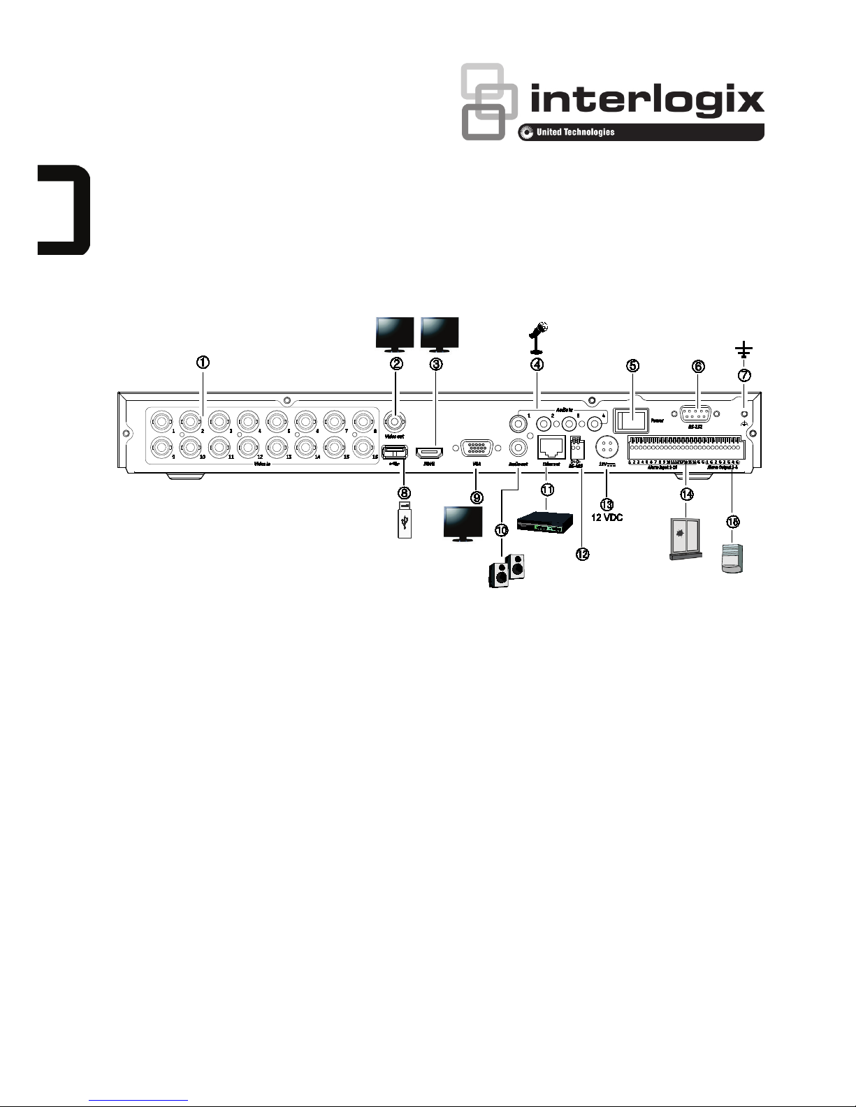
1: Back panel connections
1. Connect up to 16 analog cameras to BNC-type
connectors (depends on the recorder model).
2. Connect one CCTV monitor (BNC-type
connector).
3. Connect to a HDTV. The HDMI connection
supports both digital audio and video.
4. Connect four audio inputs to RCA connectors.
5. Power switch (on/off).
6. Connect to a RS-232 device.
7. Connect to ground.
8. Connect to an optional USB device such as a
mouse, CD/DVD burner or HDD.
9. Connect to a VGA monitor.
10. Connect to speakers for audio output.
11. Connect to a network.
12. Connect to a RS-485 device such as a PTZ
camera or a keypad.
13. Connect to the 12 VDC PSU (included).
14. Connect up to 16 alarm inputs.
15. Connect up to four alarm outputs.
Default IP address: 192.168.1.82
Page 2
2 TVR 15HD Quick Start Guide
Figure
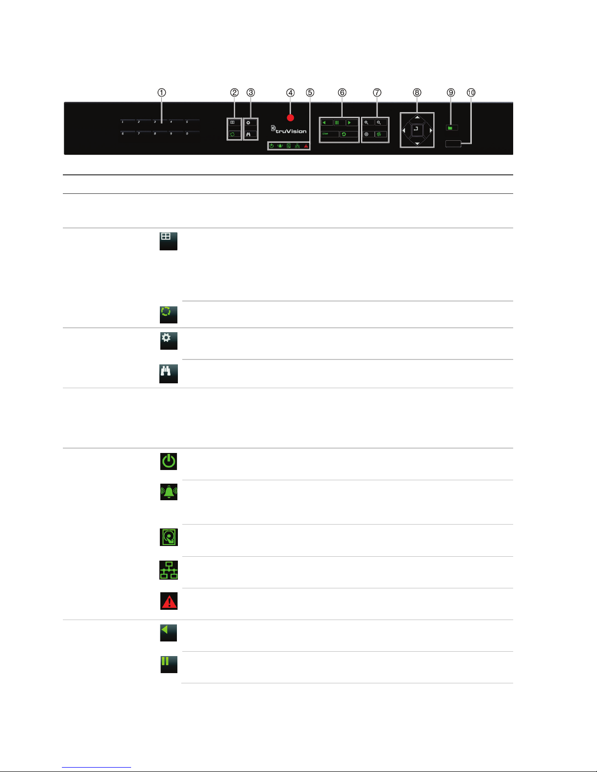
2: Front panel controls (8-channel model shown)
For detailed information on all the button functions, please
refer to the user manual.
Name Description
1
. Channel buttons Switch between different cameras in live, PTZ control or playback modes.
Use the soft keyboard to enter numerals 0 to 9.
2
. Display buttons
Display: In multiview mode, toggle through the various multiviews (full, quad,
1+5, 1+7, 9 and 16).
In HDD information mode and user management mode delete a selected item. In
PTZ mode, delete a selected key point. In Log Search mode, display the details
of a log file in Log Search result.
Seq: In Live View mode, start/stop sequencing cameras on the current monitor.
3
.
Menu and
Search buttons
Menu: Enter/exit the main menu.
Search: In live view, enter the advanced search menu.
4
. IR receiver Receiver for IR remote.
To connect the remote control to the recorder, press the Device button, enter the
device address, and press Enter. See “IR remote control” Error! Bookmark not
defined. for more information.
5
. Status LEDs
Power: A steady green light indicates the recorder is working correctly. Red
indicates a fault.
Event Alarm: A flashing red light indicates that there is a sensor Alarm In or
another alarm such as motion or tampering. No light indicates that there is no
alarm.
HDD: HDD indicator blinks red when data is being read from or written to the
HDD. A steady red light indicates an HDD exception or error.
Tx/Rx: Steady green indicates a normal network connection. No light indicates
that it is not connected to a network.
Technical Alarm: A steady red light indicates that there is a technical alarm from
the recorder. No light indicates that there is no alarm.
6
.
Playback
buttons
Reverse: In live view mode, use to play back the earliest video. In playback
mode, playback a camera in the reverse direction.
Pause: In live view, freeze the last image of the live display for all active cameras
displayed. In playback mode, stop playback.
Page 3
TVR 15HD Quick Start Guide 3
Name Description
Play: In live view mode, play all day playback of the current camera (upper-left
video tile if in multiview mode). In playback mode, play back a camera in the
forward direction. In search mode, play back a selected video or view a
snapshot. In PTZ mode, do an auto tour.
Live: Switch to live view mode.
Replay
: In playback mode, start playing the current file. Starts at the beginning of
the file.
7
. PTZ buttons
Zoom +/-: In live view mode, playback mode, and PTZ control mode use this
button to zoom in and out. Also use them to navigate within menus.
Preset: In PTZ Control mode, press Preset and a numeric button to call the
specified preset.
Also use to edit holiday mode, video search mode, HDD selection mode, user
management mode, bookmark management, and bookmark search.
Tour: In PTZ Control mode, press Tour and a numeric button to call the specified
shadow tour.
Also use to scroll between calendar months and to navigate in a text field.
8
. Direction
The DIRECTION buttons are used to navigate between different fields and items
in menus.
Enter button
The ENTER button is used to confirm selection in any of the menu modes.
9
. Archive button
Press once to enter quick archive mode. Press twice to start archiving. Indicator
blinks green when data is being written to backup device.
10
. USB Interface
Universal Serial Bus (USB) port for additional devices such as a USB mouse,
CD/DVD burner, or USB Hard Disk Drive (HDD).
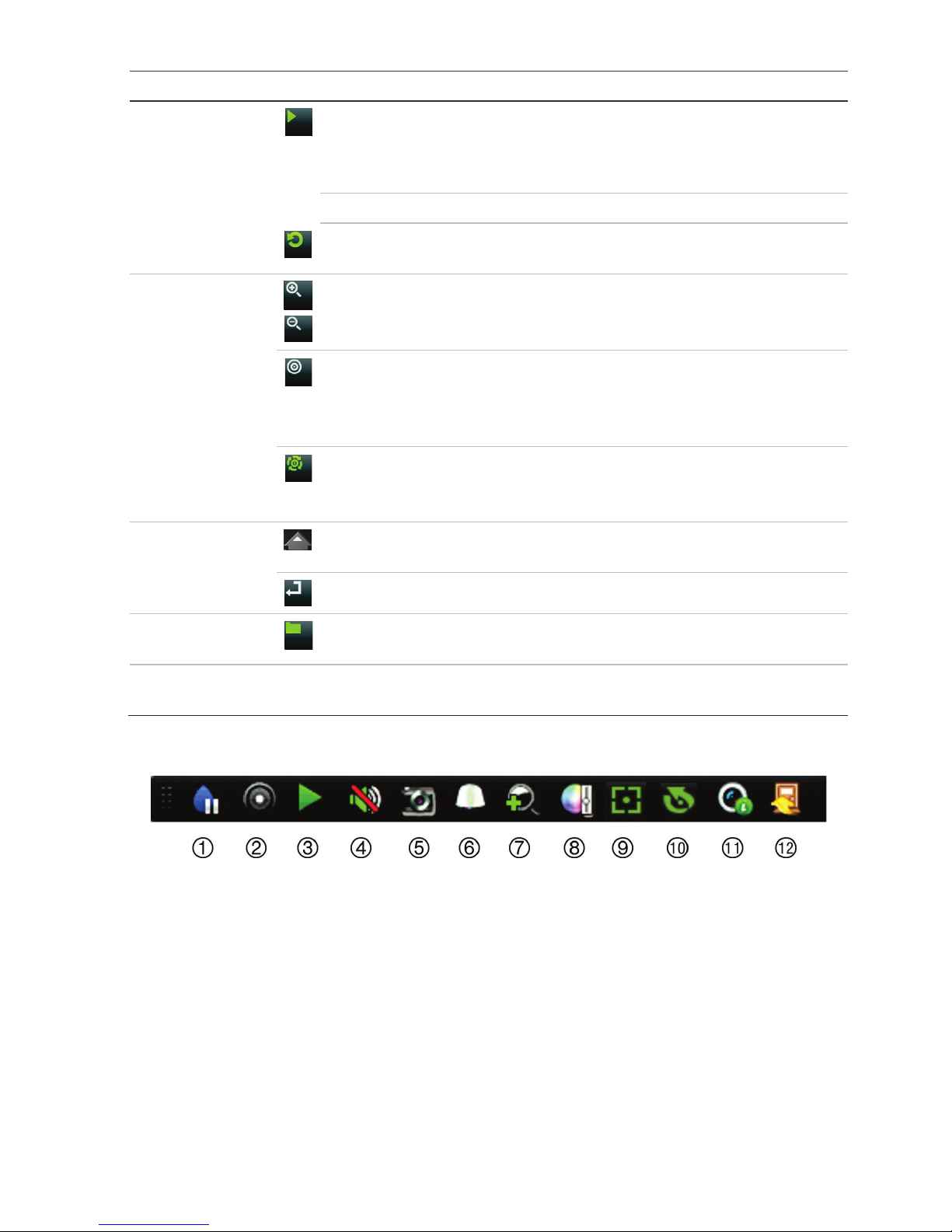
Figure
3: Live view toolbar
1. Pause: Freeze live image of the selected
camera.
2. Start Manual recording: Start/stop manual
recording.
3. Instant Playback: Play back the recorded
video from the last five minutes.
4. Audio On: Enable/disable audio output.
5. Snapshot: Capture a snapshot of a video
image.
6. PTZ Control: Enter PTZ control mode.
7. Digital Zoom: Enter digital zoom mode.
8. Image Settings: Modify the image lighting levels.
9. Auxiliary Focus: Automatically focus the camera
lens
10. Lens Initialization: Initialize the lens of a camera
with a motorized lens
11. Stream Information: Display the real-time frame
rate, bit rate, resolution and video compression.
12. Close: Close the toolbar.
Page 4

4 TVR 15HD Quick Start Guide
Package contents
The TruVision DVR 15HD (model TVR 15HD)
is shipped with the following items:
• IR (infrared) remote control
• Two AAA batteries for the remote control
• AC power cords
• 12 VDC PSU
• USB mouse
• DVR
• CD with software and manuals
• TruVision DVR 15HD Quick Start Guide
• TruVision DVR 15HD User Manual (on CD)
• TruVision Recorder Operator Guide (on
CD)
Installation environment
Refer to the user manual for detailed
information, but observe these important
requirements:
• Place the unit in a secure location.
• Ensure that the unit is in a well-ventilated
area.
• Do not expose the unit to rain or moisture.
Quick install
Recommended steps for setting up the
recorder:
1. Connect all the devices required to the
back panel of the recorder. See Figure 1
on page 1.
Basic connections:
Connect the cameras to the BNC camera
inputs and monitor A to the BNC, VGA or
HDMI output. Connect the mouse to the
USB port in the front panel.
Optional connections:
All the other connections shown are
optional and depend upon installation
requirements.
2. Connect the power supply to the unit and
turn on the power.
3. Set up the unit with the required settings
using the setup Wizard.
First-time use
The recorder has an express installation
wizard that lets you easily configure basic
recorder settings when first used. It configures
all cameras simultaneously. The configuration
can then be customized as required.
By default, the setup wizard will start once the
recorder has loaded. The wizard walks you
through some of the more important settings
of your recorder. Select the preferred
language for the system and then enter the
administrator password. You must define a
high-security admin password before you can
access the unit. There is no default password
provided.
The wizard will then guide you through the
menus to set the time and date, network
configuration, HDD management, and
recording configuration.
When all the required changes have been
entered, click Finish to exit the wizard. The
recorder is now ready to use. Recording starts
automatically.
Operating the recorder
There are several ways to control the unit:
• Front panel control
• IR remote control
• Mouse control
• Web browser control
• TVK-800 keypad
• Software (TruVision Navigator, TVRmobile)
Front panel
The buttons on the front panel control most
functions. See Figure 2 on page 2 for the
locations of the controls.
IR remote control
The IR remote control buttons are similar to
those on the front panel. Place the two AAA
batteries in the remote control.
Page 5
TVR 15HD Quick Start Guide 5
To connect the remote control to the
recorder:
1. Press Menu on the front panel or right-click
the mouse and select Menu. The main
menu screen appears.
2. Select Display mode settings > Monitor.
3. Check the recorder’s device address value.
The default value is 255. The device
address is valid for all IR controls.
4. On the remote control press the Device
button.
5. Enter the device address value. It must be
the same as that on the recorder.
6. Press OK on the remote control.
USB mouse
The USB mouse provided with the recorder
operates all the functions of the recorder,
unlike the front panel, which has limited
functionality. The mouse lets you navigate and
make changes to settings in the user
interface.
Connect the mouse to the recorder by
plugging the mouse USB connector into the
USB port on the back or front panel. The
mouse is immediately operational and the
pointer should appear.
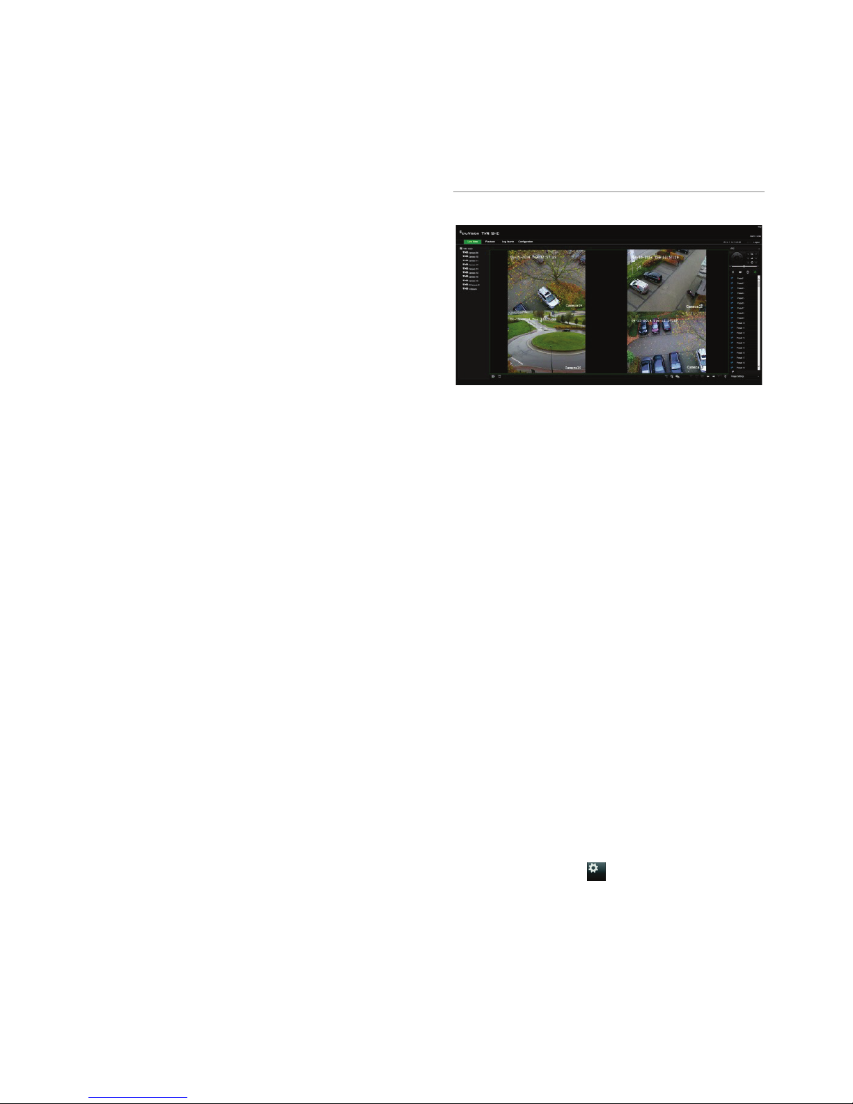
Web browser control
The recorder’s Web browser lets you view,
record, and play back videos as well as
manage all aspects of the recorder from any
PC with Internet access. The browser’s easyto-use controls give you quick access to all
recorder functions.
To access the unit, open a web browser and
enter the IP address assigned to the recorder
as a web address. In the logon screen, enter
the user ID and password:
The default values for recorder network
settings are:
• DHCP: Disabled by default.
• IP address - 192.168.1.82
• Subnet mask - 255.255.255.0
• Gateway address - 192.168.1.1
• Server Port: 8000
• HTTP Port: 80
• RTSP port: 554
Note: The following ports need to be
forwarded in the router in order to connect
properly: Server port and RTSP port.
Figure 4: Web browser interface
Live view mode
Live mode is the normal operating mode of the
unit where you watch live pictures from the
cameras.
Regularly used functions in live view can be
quickly accessed by clicking the left-button of
the mouse when its cursor is on the camera
image. The live view toolbar appears. See
Figure 3 on page 3 for a description of the
functions available.
Configuring the recorder
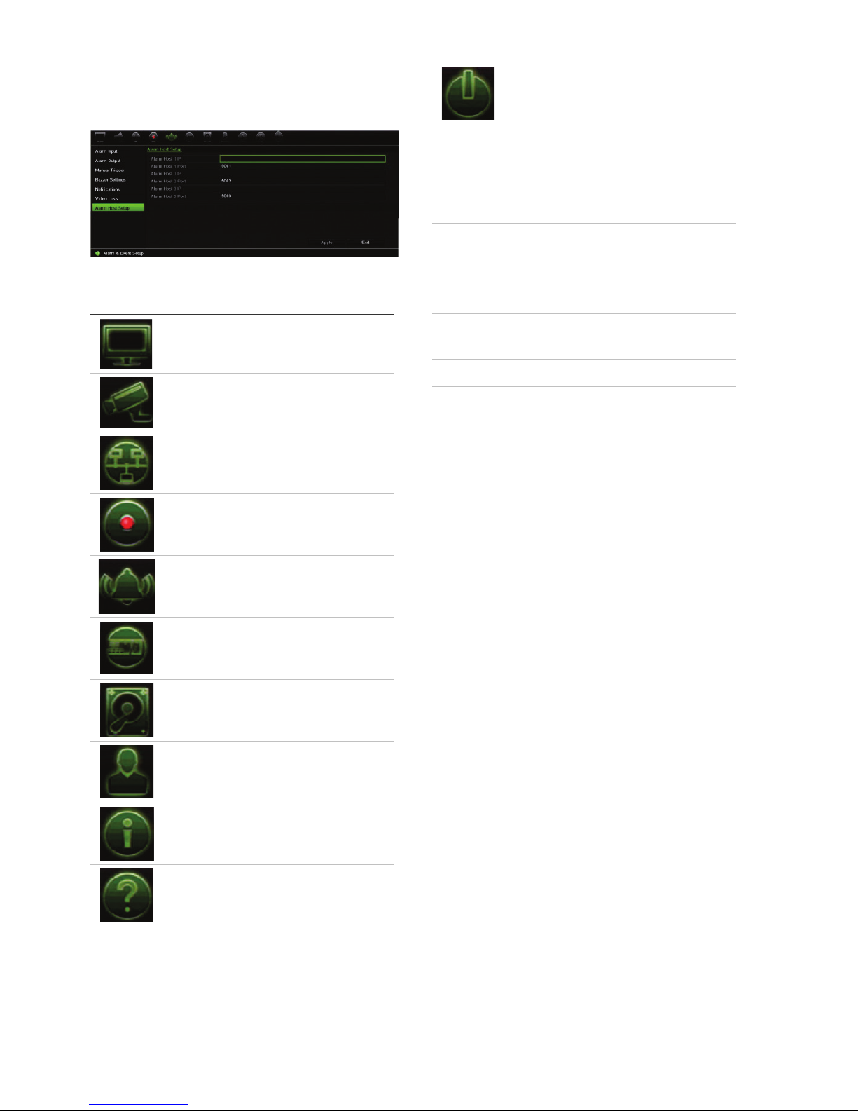
The recorder has an icon-driven menu
structure that allows you to configure the unit’s
parameters. Each command icon displays a
screen that lets you edit a group of settings.
Most menus are available only to system
administrators.
Refer to the recorder user manual for detailed
information on configuring the unit.
To access the main menu from live view:
• Press the Menu button on the remote
control or front panel.
- Or -
• Right-click the mouse and select Menu
from the pop-up menu.
Page 6
6 TVR 15HD Quick Start Guide
The main menu screen appears. Move the
mouse over a command icon in the menu
toolbar and click to select it.
Description of the command icons in the
menu toolbar:
Configures display settings.
Configures analog and IP
camera settings.
Configures standard network
settings.
Configures recording settings.
Configures alarm and event
settings.
Configures system settings.
Configures storage
management.
Configures user settings.
View system information.
Provides reference information
to the various toolbars and
menus within the interface.
Provides access to logout,
reboot and shutdown options.
Specifications
Power supply
: 12 VDC
Power consumption (without HDD
):
TVR 1504cHD
TVR 1508HD
TVR 1516HD
≤ 15 W
≤ 20 W
≤ 20 W
Operating
temperature
:
-10 to +55 ºC
(14 to 131 °F)
Relative humidity
: 10 to 90%
Dimensions (W x H x D)
:
TVR 1504cHD
315 × 242 × 45 mm
(12.4 × 9.5 × 1.8 in.)
TVR 1508HD
TVR 1516HD
380 × 320 × 48 mm
(15.0 × 12.6 × 1.9 in.)
Weight
(without HDD):
TVR 1504cHD ≤ 1.5 kg (3.3 lb.)
TVR 1508HD ≤ 2.5 kg (5.5 lb.)
TVR 1516HD ≤ 2.5 kg (5.5 lb.)
Page 7
TVR 15HD Quick Start Guide 7
Legal and Regulatory information
Copyright
©
2017 United Technologies Corporation. All rights reserved.
Interlogix is part of UTC Climate, Controls & Security, a unit of
United Technologies Corporation. All rights
reserved
Trademarks and patents
Trade names used in this document may be trademarks or registered tra
demarks of the manufacturers or
vendors of the respective products.
Manufacturer
Interlogix
2955 Red Hill Avenue, Costa Mesa, CA 92626
-5923, USA
Authorized EU manufacturing representative:
UTC Fire & Security B.V.
Kelvinstraat 7, 6003 DH Weert, The
Netherlands
FCC compliance
Class
B: This equipment has been tested and found to comply with the limits for a Class B digital device,
pursuant to part 15 of the FCC Rules. These limits are designed to provide reasonable protection against harmful
interference in a residential installation. This equipment generates, uses, and can radiate radio frequency energy
and, if not installed and used in accordance with the instructions, may cause harmful interference to radio
communications.
There is no guara
ntee that interference will not occur in a particular installation. If this equipment does cause
harmful interference to radio or television reception, which can be determined by turning the equipment off and
on, the user is encouraged to try to correct th
e interference by one or more of the following measures:
•
Reorient or relocate the receiving antenna.
•
Increase the separation between the equipment and receiver.
•
Connect the equipment into an outlet on a circuit different from that to which the receiver is connected.
•
Consult the dealer or an experienced radio/TV technician for help.
FCC
conditions
This device complies with Part 15 of the FCC Rules. Operation is subject to the following two conditions:
(1) This device may not cause harmful interfer
ence.
(2) This Device must accept any interference received, including interference that may cause undesired
operation.
Canada
This Class
B digital apparatus complies with CAN ICES-003 (B)/NMB-3 (B).
Cet appareil numérique de la classe
B est conforme à la norme CAN ICES-003 (B)/NMB-3 (B).
ACMA compliance
Notice!
This is a Class B
product. In a domestic environment this product may cause radio interference in which
case the user may be required to take adequate measures.
Certification
EU directives
This product and
- if applicable - the supplied accessories too are marked with "CE" and comply therefore with
the applicable harmonized European standards listed under the EMC Directive 2014/30/EU, the RoHS Directive
2011/65/EU.
2012/19/EU (WEEE directive): Products marked with this symbol cannot be disposed of as unsorted municipal
waste in the European Union. For proper recycling, return this product to your local supplier upon the purchase of
equivalent new equipment, or dispo
se of it at designated collection points. For more information see:
www.recyclethis.info.
2013/56/EU & 2006/66/EC (battery directive)
: This product contains a battery that cannot be disposed of as
unsorted municipal waste in the European Union. See the product documentation for specific battery information.
The battery is marked with this symbol, which may include lettering to indicate cadmium (Cd), lead (Pb), or
mercury (Hg). For proper recycling, return the battery to your supplier or to a designated
collection point. For
more information see: www.recyclethis.info.
Contact information
For contact information, see www.interlogix.com or www.utcfssecurityproducts.eu
Page 8

 Loading...