

Interlogix TVR-1108-2T, TVR-1104-500/EA, TVR-1116-2T, TVR-1116-4T, TVR-1104-1T/EA User Manual
...
TruVision DVR 11 and
DVR 11c User Manual
P/N 1072595B-EN • REV 1.0 • ISS 28JAN13

Copyright
©
2013 UTC Fire & Security Americas Corporation, Inc.
Interlogix is part of UTC Climate Controls & Security, a unit of United
Technologies Corporation. All right s reserved
Trademarks and patents
Th
e TruVision name and logo are trademarks of UTC Fire & Security.
Other trade names used in this document m ay be trademarks or registered
trademarks of the manufacturers or vendors of
the respective products.
Manufacturer
UTC Fire & Security Americas Corporation, Inc.
2955 Red Hill Avenue, Costa Mesa, CA 92626
-5923, USA
Authorized EU manufacturing representative:
UTC Fire & Security B.V.
Kelvinstraat 7, 6003 DH Weert, The Netherlands
Certification
N4131
FCC compliance
Class B:
This equipment has been tested and found to comply with the
limits for a Class B digital device, purs uant to part 15 of the FCC Rules.
These limits are designed to provide reasonable protection against harmful
interference in a residential inst all ation. T
his equipment generates, uses,
and can radiate radio frequency energy and, if not installed and used in
accordance with the instructions, may cause harmful interference to radio
communications.
There is no guarantee that interference will not occur in a pa
rticular
installation. If this equipment does cause harmful interference to r adi o or
television reception, which can be determined by turning the equipment off
and on, the user is encouraged to try to correct the interference by one or
more of the followin
g measures:
•
Reorient or relocate the receiving antenna.
•
Increase the separation between the equipment and receiver.
•
Connect the equipment into an outlet on a circuit different from that to
which the receiver is connected.
•
Consult the dealer or an experienced radio/TV technician for help.
European Union
directives
12004/108/EC (EMC directive):
Hereby, UTC Fire & Security declares t hat
this device is in compliance
or with the essential requirements and other
relevant provisions of Directive
2004/108/EC.
2002/96/EC (WEEE directive): Pr oduc ts marked with this symbol cannot be
disposed of as unsorted municipal wast e in the European Union. For proper
recycling, return this product to your local supplier upon the purchase of
equivalent new equ
ipment, or dispose of it at designated collection points.
For more information see: www.recyclethis.info.
2006/66/EC (battery directive):
This product contains a battery that cannot
be disposed of as unsorted municipal waste in the European Union. See
the
product documentation for specific battery information. The battery is
marked with this symbol, which may inc lude lettering to indicate cadmium
(Cd), lead (Pb), or mercury (Hg). For proper recycling, return the batter y to
your supplier or to a designat
ed collection point. For more inform ation see:
www.recyclethis.info.
Contact information
For contact information
, see www.utcfireandsecurity.com or
www.utcfssecurityproducts.eu

TruVision DVR 11 and DVR 11c User Manual i
Content
Chapter 1 Product introduction 1
Product overview 1
Chapter 2 Installation 3
Installation environment 3
Unpacking the DVR and its accessories 3
Back panel 4
Monitor connections 6
Audio inputs and output 6
RS-485 port 7
RS-232 port 7
PTZ dome camera set up 7
Connecting a KTD-405 keypad and dome camera to the
DVR 12
Brackets 13
Chapter 3 Getting started 15
Turning on and off the DVR 15
Using the setup wizard 16
Chapter 4 Recording 19
Initializing the recording settings 19
Defining a recording schedule 21
Daily schedules 22
Holiday schedules 23
Motion detection schedules 23
External alarm schedules 23
Protecting recorded files 24
Capturing text insertions 25
Chapter 5 Alarm settings 27
Description of alarm notification types 27
Setting up motion detection 27
Setting up external alarms 30
Triggering or clearing alarm outputs manually 32
Setting up system notifications 32
Detecting video loss 33
Detecting video tampering 34
Chapter 6 Network settings 35
Configuring general network settings 35
Configuring PPPoE 36
Configuring DDNS 37
Configuring an NTP server 38

ii TruVision DVR 11 and DVR 11c User Manual
Configuring email 38
Configuring SNMP 39
Configuring a remote alarm host 40
Configuring multicast 40
Configuring the server and HTTP ports 41
Configuring the RTSP service port 41
Checking network status 41
Exporting network packet data 43
Chapter 7 HDD management 45
Initializing HDDs 45
Setting the HDD quota 45
Setting the HDD property 46
Checking HDD status 46
Configuring HDD alarms 47
Checking the S.M.A.R.T. information 47
Chapter 8 Operating instructions 49
Controlling the DVR 49
Using the front panel 49
Using the mouse 51
Using the IR remote control 52
Menu overview 55
Chapter 9 Live view 59
Description of live view 59
Video output 60
Controlling live view 60
Single and multiview display formats 61
Sequencing cameras 62
Accessing frequently used commands 63
Configuring live view 65
Configuring time and date 67
General settings 68
V-stream encoding 71
Chapter 10 Controlling a PTZ camera 73
Configuring PTZ settings 73
Calling up presets, tours and shadow tours 74
Setting and calling up presets 75
Setting and calling up preset tours 77
Setting and calling up a shadow tour 79
Chapter 11 Playing back a recording 81
Overview of the playback window 81
Instant playback 83
All-day playback 84
Searching recorded video 85

TruVision DVR 11 and DVR 11c User Manual iii
Playing back recordings by time and video type 86
Playing back recordings by event 87
Slideshow of snapshots 88
Playing back recordings from the system log 88
Motion search 90
Playing back frame-by-frame 91
Digital zoom in playback 91
Chapter 12 Archiving recorded files 93
Archiving files 93
Creating and archiving video clips 95
Archiving snapshots 96
Managing backup devices 97
Playing back archived files on a PC 97
Chapter 13 DVR management 99
Configuring the RS-232 port 99
Updating system firmware 100
Restoring default settings 100
Viewing system information 101
Searching system logs for events 102
Chapter 14 Camera settings 105
Configuring the OSD settings 105
Setting up privacy masking 106
Adjusting video image settings 107
Chapter 15 User management 109
Adding a new user 109
Customizing a user’s access privileges 110
Deleting a user 112
Modifying a user 112
Changing the Admin password 112
Chapter 16 Using the web browser 113
Windows Vista and 7 users 113
Accessing the web browser 114
Web browser overview 114
Using the web browser to configure the device 116
Searching and playing back recorded video 117
Searching for event logs 119
Controlling a PTZ dome camera in the web browser 119
Capturing text insertions 120

iv TruVision DVR 11 and DVR 11c User Manual
Appendix A Specifications 123
Appendix B PTZ protocols 125
Appendix C KTD-405 keypad 127
Supported firmware 127
Wiring the keypad 127
Setting up the keypad to work with the TVR 11 128
Operating the keypad 130
Appendix D Maximum pre-recording times 135
Appendix E Supported PTZ commands 137
Appendix F Default menu settings 139
Glossary 147
Index 149

TruVision DVR 11 and DVR 11c User Manual 1
Chapter 1
Product introduction
Product overview
This is the TruVision DVR 11(TVR 11) and TruVision DVR 11c (TVR 11c) User
Manual for models:
Table 1: Product codes for TVR 11
Americas
Description
TVR
-1108-1T TruVision DVR 11, H.264, 8 ch, 1 TB Storage
TVR
-1108-2T TruVision DVR 11, H.264, 8 ch, 2 TB Storage
TVR
-1116-2T TruVision DVR 11, H.264, 16 ch, 2 TB Storage
TVR
-1116-4T TruVision DVR 11, H.264, 16 ch, 4 TB Storage
EMEA
TVR
-1104-500/EA TruVision DVR 11, H.264, 4 ch, 500 GB Storage
TVR
-1104-1T/EA TruVision DVR 11, H.264, 4 ch, 1 TB Storage
TVR
-1104-2T/EA TruVision DVR 11, H.264, 4 ch, 2 TB Storage
TVR
-1108-1T/EA TruVision DVR 11, H.264, 8 ch, 1 TB Storage
TVR
-1108-2T/EA TruVision DVR 11, H.264, 8 ch, 2 TB Storage
TVR
-1116-2T/EA TruVision DVR 11, H.264, 16 ch, 2 TB Storage
TVR
-1116-4T/EA TruVision DVR 11, H.264, 16 ch, 4 TB Storage
TVR
-1104D-500/EA TruVision DVR 11, H.264, 4 ch, DVD/CD, 500 GB St orage
TVR
-1104D-1T/EA TruVision DVR 11, H.264, 4 ch, DVD/CD, 1 TB St orage
TVR
-1104D-2T/EA TruVision DVR 11, H.264, 4 ch, DVD/CD, 2 TB St orage
TVR
-1108D-1T/EA TruVision DVR 11, H.264, 8 ch, DVD/CD, 1 TB St orage
TVR
-1108D-2T/EA TruVision DVR 11, H.264, 8 ch, DVD/CD, 2 TB St orage
TVR
-1116D-1T/EA TruVision DVR 11, H.264, 16 ch, DVD/CD, 1 TB Storage
TVR
-1116D-2T/EA TruVision DVR 11, H.264, 16 ch, DVD/CD, 2 TB Storage

0BChapter 1: Product introduction
2 TruVision DVR 11 and DVR 11c User Manual
Table 2: Product codes for TVR 11c
TVR
-1104c-500 TruVision DVR 11c, H.264, 4 ch, 500 GB Storage
TVR
-1104c-1T TruVision DVR 11c, H.264, 4 ch, 1 TB Storage
Note: Models are shipped with the power cords for their region.
For regions not listed in Table 1 or Table 2 above, please contact your local
supplier.
The TVR 11 and TVR 11c are versatile, user-friendly embedded digital video
recorders (DVR).
The TVR 11 allows end-users to record 4, 8 or 16 analog cameras at CIF in r eal
time (25/30 fps), while providing integration with the UTC portfolio of security
solutions, and offering a seamless product experience within the TruVision
brand.
The TVR11c is a four-channel version of the TVR11 that allows end users to
record four channel analog cameras at CIF in real time.
The dual streaming functionality allows the user to set up different settings for
recording and streaming video in live view mode.
Both DVRs can fully integrate with the license-free TruVision Navigator soft ware,
which is ideal for the most commercial applications. Their easy and intuitive-touse web browser interface enables remote configuration and secure viewing,
searching, and playing back of video from computers connected via the Internet.

TruVision DVR 11 and DVR 11c User Manual 3
Chapter 2
Installation
This section describes how to install the DVR unit.
Installation environment
When installing your product, consider these factors:
• Ventilation
• Temperature
• Moisture
• Chassis load
Ventilation: Do not block any ventilation openings. Install in accordance with the
manufacturer’s instructions. Ensure that the location planned for the installation
of the unit is well ventilated.
Temperature: Consider the unit’s operating temperature (-10 to +55 ºC, 14 to
131 °F) and noncondensing humidity specifications (10 to 90%) before choosing
an installation location. Extremes of heat or cold beyond the specified operating
temperature limits may reduce the life expectancy of the DVR. Do not install the
unit on top of other hot equipment. Leave 44 mm (1.75 in.) of space between
rack-mounted DVR units.
Moisture: Do not use the unit near water. Moisture can damage the internal
components. To reduce the risk of fire or electric shock, do not expose this unit to
rain or moisture.
Chassis: Equipment weighing less than 15.9 kg (35 lb.) may be placed on top of
the unit.
Unpacking the DVR and its accessories
When you receive the product, check the package and contents for damage, and
verify that all items are included. There is an item list included in the package. If
any of the items are damaged or missing, please contact your local supplier.

1BChapter 2: Installation
4 TruVision DVR 11 and DVR 11c User Manual
Items shipped with the product include:
• IR (infrared) remote control
• Two AAA batteries for the remote control
• AC power cords
• USB mouse
• DVR
• Video loop through cable (TVR 11 only)
• CD with software and manuals
• TruVision DVR 11 Quick Start Guide or TruVision DVR 11c Quick Start Guide
• TruVision DVR 11 User Manual or TruVision DVR 11c User Manual (on CD)
Back panel
The figures on the next page show the back panel connections and describe
each connector on typical TVR 11 and TVR 11c digital video recorders. Details
may vary for specific models.
Before powering up the DVR, connect the cameras and a main monitor for basic
operation. Once all required connections are done, enter the relevant data in the
setup wizard (see page 16).
1BChapter 2: Installation
TruVision DVR 11 and DVR 11c User Manual 5
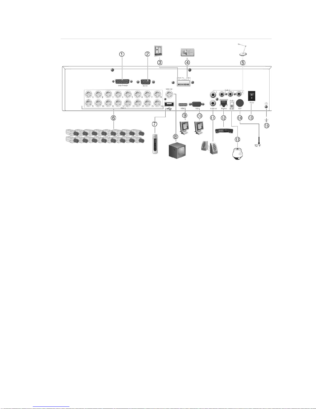
Figure 1: TVR 11 back panel connections (16-channel model shown)
1. Loop through for up to 16 analog cameras
(depends on DVR model).
2. Connect to a RS-232 device.
3. Connect up to four alarm input cables to
relay outputs.
4. Connect one alarm relay output.
5. Connect four audio inputs to RCA
connectors.
6. Connect up to 16 analog cameras to BNC
connectors (depends on model of DVR).
7. Connect to an optional USB device such as
a mouse, CD/DVD burner or HDD. The
DVR supports both a USB DVD and a USB
HD on the front and rear USB ports.
8. Connect one CCTV monitor (CVBS
connector).
9. Connect to a HDTV. The HDMI connection
supports both digital audio and video.
10. Connect to a VGA monitor.
11. Connect to speakers for audio output.
12. Connect to a network.
13. Connect to a RS-485 device such as a PTZ
camera or a keypad.
14. Connect to the PSU (12 VDC).
15. Power switch (on/off).
16. Connect to ground.
1BChapter 2: Installation
6 TruVision DVR 11 and DVR 11c User Manual
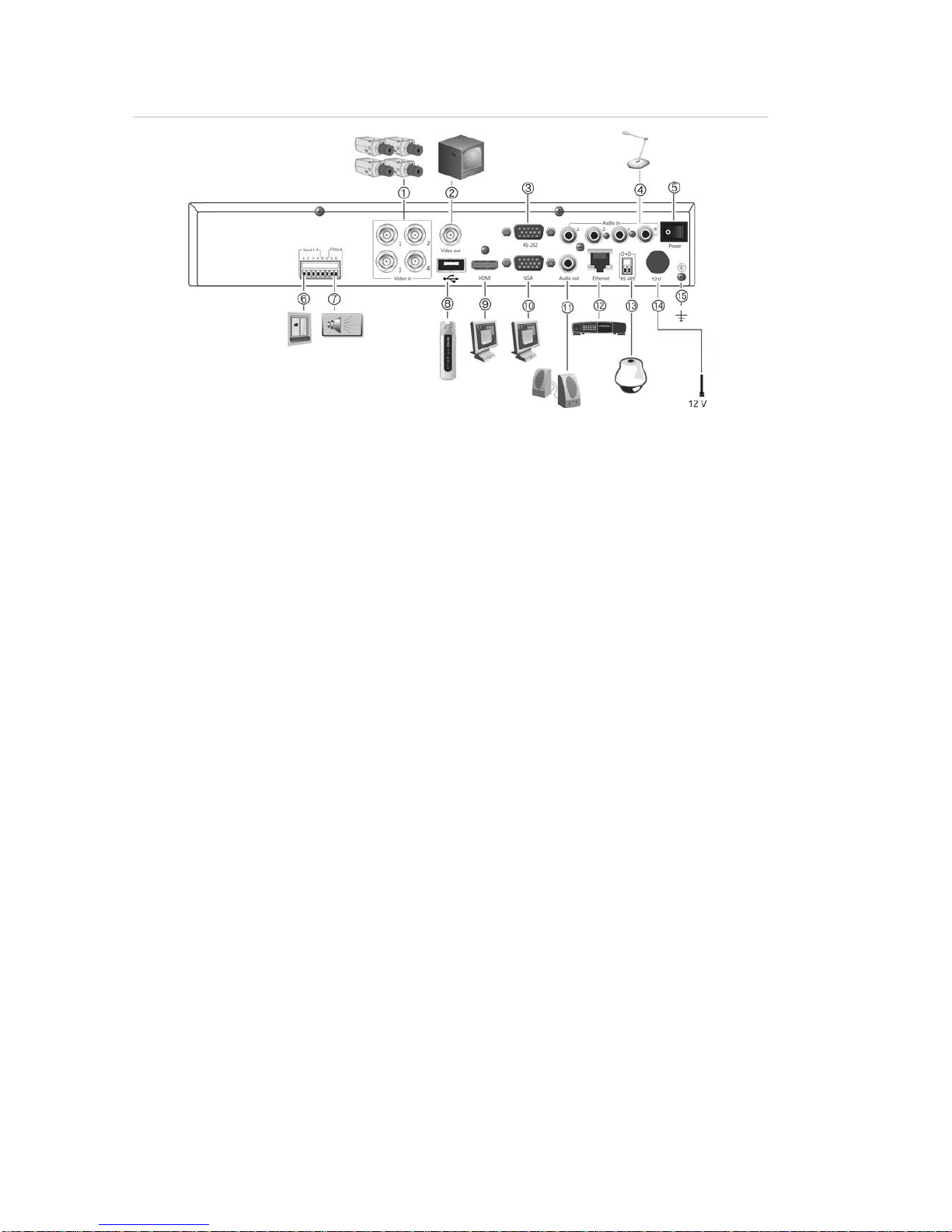
Figure 2: TVR 11c back panel connections
1. Connect up to 4 analog cameras to BNC
connectors.
2. Connect one CCTV monitor (CVBS
connector).
3. Connect to a RS-232 device.
4. Connect four audio inputs to RCA
connectors.
5. Power switch (on/off).
6. Connect up to four alarm input cables to
relay outputs.
7. Connect one alarm relay output.
8. Connect to an optional USB device such as
a mouse, CD/DVD burner or HDD. The
DVR supports both a USB DVD and a USB
HD on the front and rear USB ports.
9. Connect to a HDTV. The HDMI connection
supports both digital audio and video.
10. Connect to a VGA monitor.
11. Connect to speakers for audio output.
12. Connect to a network.
13. Connect to a RS-485 device such as a PTZ
camera or a keypad.
14. Connect to the PSU (12 VDC).
15. Connect to ground.
Monitor connections
Connect a monitor to one of the DVR’s outputs (BNC/VGA/HDMI). The DVR
provides a 1 Vp-p CVBS signal. See Figure 1 above for connecting a monitor t o a
DVR.
The DVR supports up to 1280 × 1024 / 60 Hz resolution in VGA. The monitor
resolution should be at least 800 × 600. Adjust your monitor accordingly to this
resolution.
Audio inputs and output
The unit is equipped with four audio inputs and one audio output. Both the audio
output and the audio inputs are line-level.

1BChapter 2: Installation
TruVision DVR 11 and DVR 11c User Manual 7
Audio i
nput RCA jack, 315 mV, 40 kohms. Unbalanced
Audio output
RCA jack, 315mV, 600 ohms. Unbalanced
Note: Line-level audio requires amplification.
RS-485 port
There is one RS-485 port on the back panel of the DVR to connect a PTZ dome
camera or keypad. See Figure 3 for the serial pin outs.
Figure 3: RS-485 pin outs
D+: Connect to the RS-485 A connection on the
dome camera or keypad.
D-: Connect to the RS-485 B connection on the
dome camera or keypad.
RS-232 port
Use the RS-232 port to connect CBR-PB3-POS (point-of-sale) and ATM devices
to the DVR such as the UTC ProBridge accessory. See “Configuring the RS-232
port” on page 99 for more information.
PTZ dome camera set up
Use the USB mouse provided or the optional keypad for local telemetry control. If
using the DVR over a network, use the web browser to control the PTZ dome
cameras or TruVision Navigator.
See Appendix B on page125 for the supported protocols, and Appendix E on
page 137 for the PTZ commands supported by each protocol.
Each PTZ camera must be set up individually. For information on configuring
PTZ dome camera settings, see Chapter 10, “Controlling a PTZ camera” on page
73.
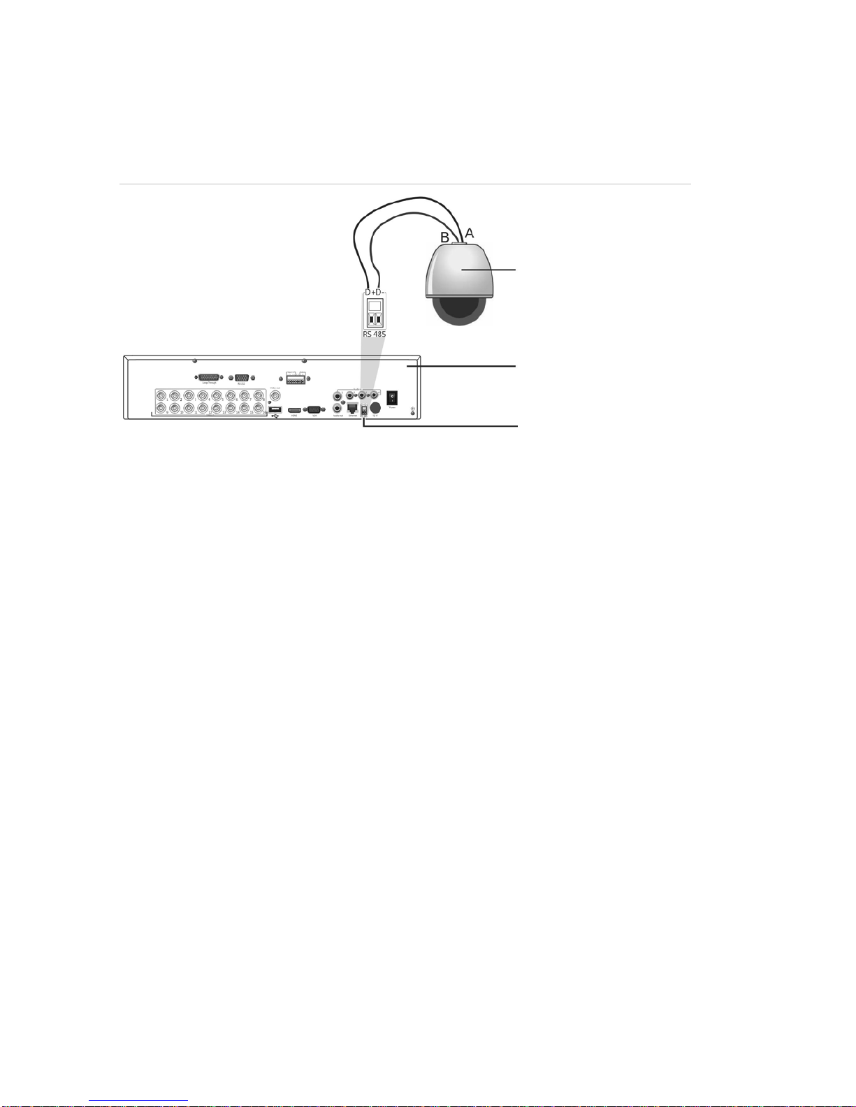
Connecting a PTZ dome camera
See Figure 4 below for how to connect a PTZ camera to the DVR. Any PTZ
dome camera can be controlled as the DVR is doing the PTZ protocol translation.
1BChapter 2: Installation
8 TruVision DVR 11 and DVR 11c User Manual
However, this setup provides only limited dome configuration (see Appendix B on
page 125 for the list of approved PTZ protocols).
Figure 4: Connecting a PTZ dome camera to the DVR for control over the network (TVR 11
back panel shown)
Dome camera
DVR back panel (TVR 11
shown)
RS-485 port
Configuring the PTZ protocols for Interlogix camera s
Before the PTZ dome cameras are assembled in their housings, set their
protocol and address DIP switches for the DVR. See Table 3 on page 9 for
different Interlogix PTZ dome camera settings.
If you are using PTZ dome cameras from another company, please refer to their
configuration instructions.
1BChapter 2: Installation
TruVision DVR 11 and DVR 11c User Manual 9
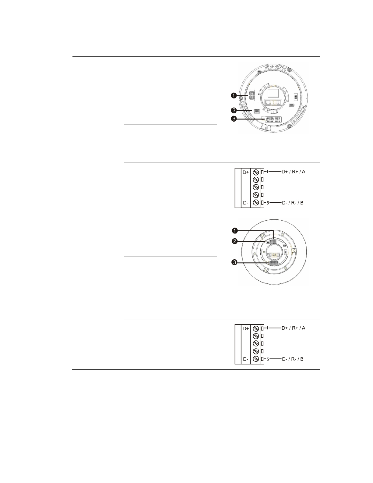
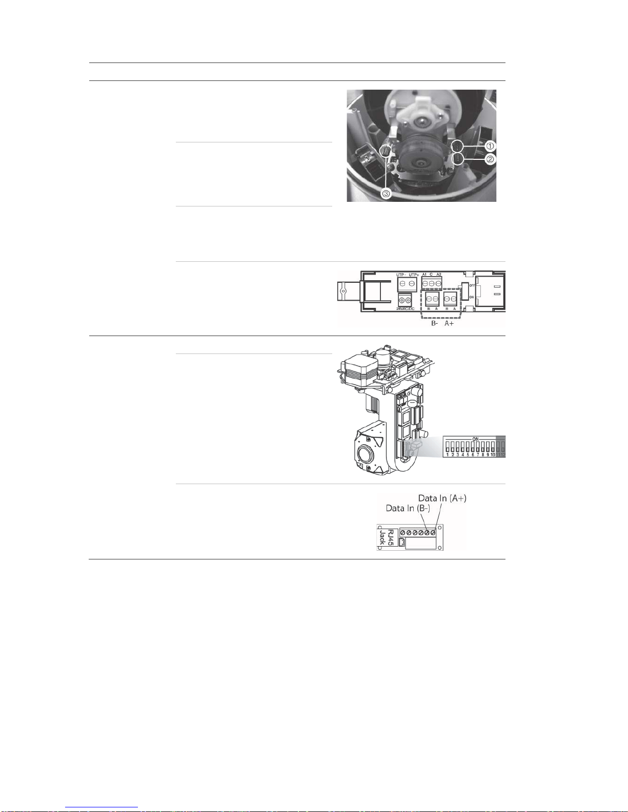
Table 3: PTZ protocols for Interlogix cameras
Camera
Switch setting
TruVision Mini PTZ
12X: Indoor Dome
Protocol DIP
switches:
• RS-485 (on DVR): 000000
1. Protocol DIP switches
2. RS-
485 communication DIP switches
3. Camera ID DIP switches
• RS-422 (on I/O
box):
100000
RS-485
communication DIP
switches:
110000
Camera ID DIP
switches:
Select the
camera ID
DIP switch
address as
required
RS-422/RS-485 data connector:
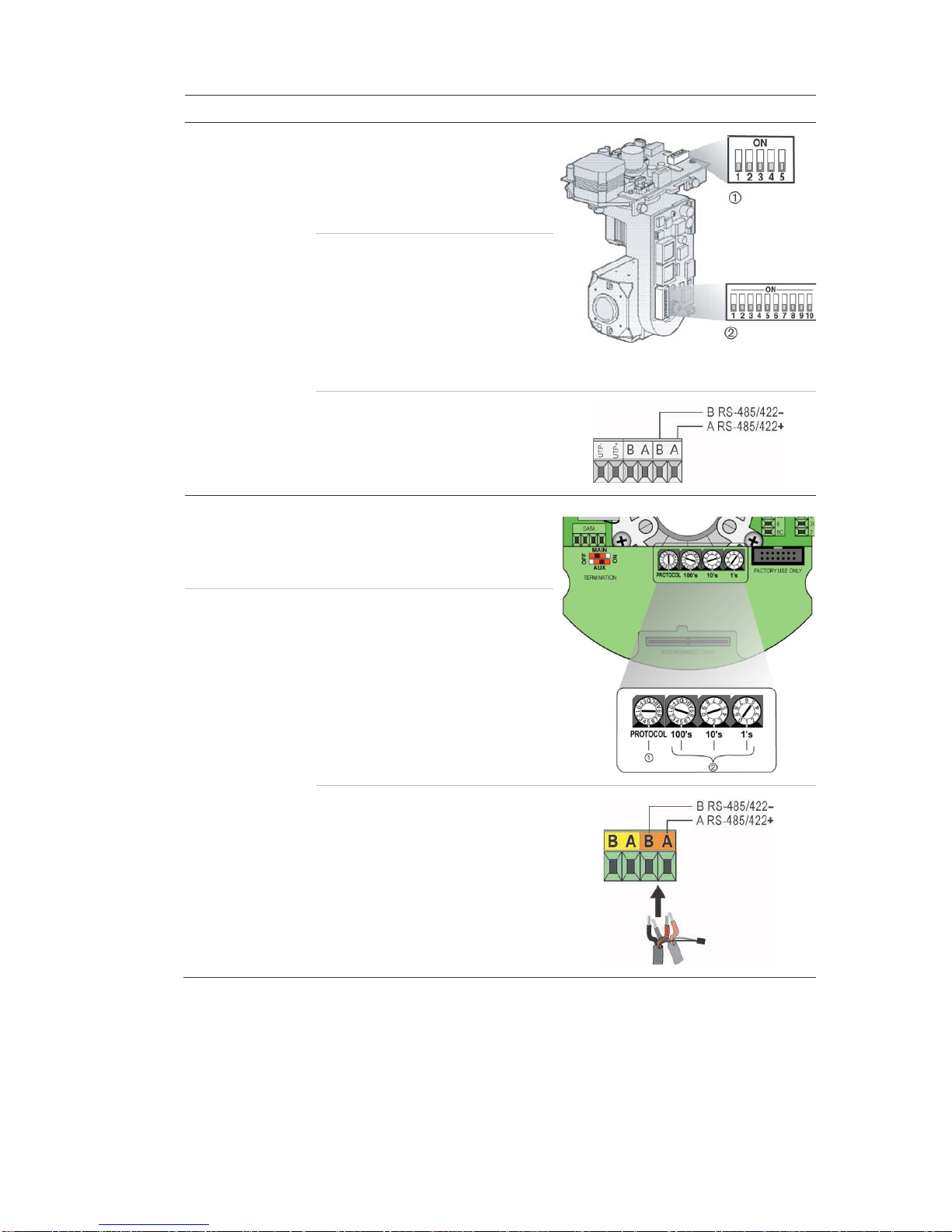
TruVision Mini PTZ
12X: Outdoor
Dome
Protocol DIP
switches:
• RS-485 (on DVR): 000000
1. Protocol DIP switches
2. RS-485 communication DIP
switches
3. Camera ID DIP switches
• RS-422 (on I/O
box):
100000
RS-485
communication DIP
switches:
110000
Camera ID DIP
switches:
Select the
camera ID
DIP switch
address as
required.
RS-422/RS-485 data connector:
1BChapter 2: Installation
10 TruVision DVR 11 and DVR 11c User Manual
Camera
Switch setting
TruVision Dome
16X PTZ
Protocol switches:
• RS-485 (on DVR):
0111
1. Address switches; 2. Baud switches;
3. Protocol switches
• RS-422 (on I/O
box):
1111
Address switches: Select the
camera ID
DIP switch
address as
required.
Baud rate: 0000 =
9600 bps
0011 =
4800 bps
RS-422/RS-485 data connector:
CyberDome
Protocol switches: NA
Address switches: Select the
camera ID
DIP switch
address as
required.
RS-485 data connector:
1BChapter 2: Installation
TruVision DVR 11 and DVR 11c User Manual 11
Camera
Switch setting
UltraView PTZ
Protocol switches:
• RS-485 (on
DVR): 01000
1. Protocol switches;
2. Address switches
• RS-422 (on I/O
box):
10000
Address switches: Select the
address
switch
address as
required.
RS-422/RS-485 data connector:
Legend
Protocol switches:
• RS-485 on DVR):
1
• RS-422 (on I/O
box):
0
Address switches: Select the
camera ID
DIP switch
address as
required.
RS-422/RS-485 data connector:
1BChapter 2: Installation
12 TruVision DVR 11 and DVR 11c User Manual
Connecting a KTD-405 keypad and dome
camera to the DVR
Use the input/output box that is supplied with the keypad to connect the KTD-405
keypad to the DVR. See Appendix C on page 127 for more information on wiring
and using the KTD-405 keypad.
As the KTD-405 keypad uses full duplex data communication, you cannot
connect the both keypad and a dome camera directly to the DVR from the RS485 port as this could cause problems on the bus. If both devices are required, it
is recommended that you use the keypad’s RS-422 connection to connect the
dome camera and the keypad’s RS-485 connection to connect the DVR. Se e
Figure 5 as well as Table 4 and Table 5 below.
Note: These connections only work with UTC PTZ protocols (see Appendix B on
page 125). If you are using another manufacturer’s PTZ protocol, it is not
possible to connect both a keypad and dome camera to the DVR.
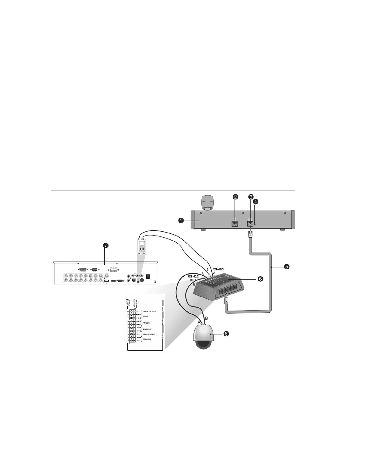
Figure 5: Connecting a PTZ dome camera and KTD-405 keypad to the DVR (TVR 11 shown)
1. KTD-405 keypad
2. RS-232 programming port
3. RS-485 and RS-422 in/out
4. RS-485 termination switch
5. RJ45 cable control (use the cable provided with
the equipment)
6. I/O box
7. DVR back panel
8. Dome camera
1BChapter 2: Installation
TruVision DVR 11 and DVR 11c User Manual 13
Table 4: UTC PTZ protocol settings
Dome: RS
-422 protocol TVR 11/TVR 11c: Interlogix RS-485
See Table 5 below for the bus addresses to consider when connecting a both
keypad and dome camera to the DVR.
Table 5: Bus addresses
DVR bus address
DVR video inputs PTZ address range
1 1-32 00-31
2 1-32 32-63
3 1-32 64-95
4 1-32 96-127
5 1-32 128-159
6 1-32 160-191
7 1-32 192-223
8 1-32 224-255
Brackets
The DVR is easily rack-mountable. The TVR 11 has a 1.5U chassis and the
TVR 11c has a 1U chassis. See Figure 6 below.
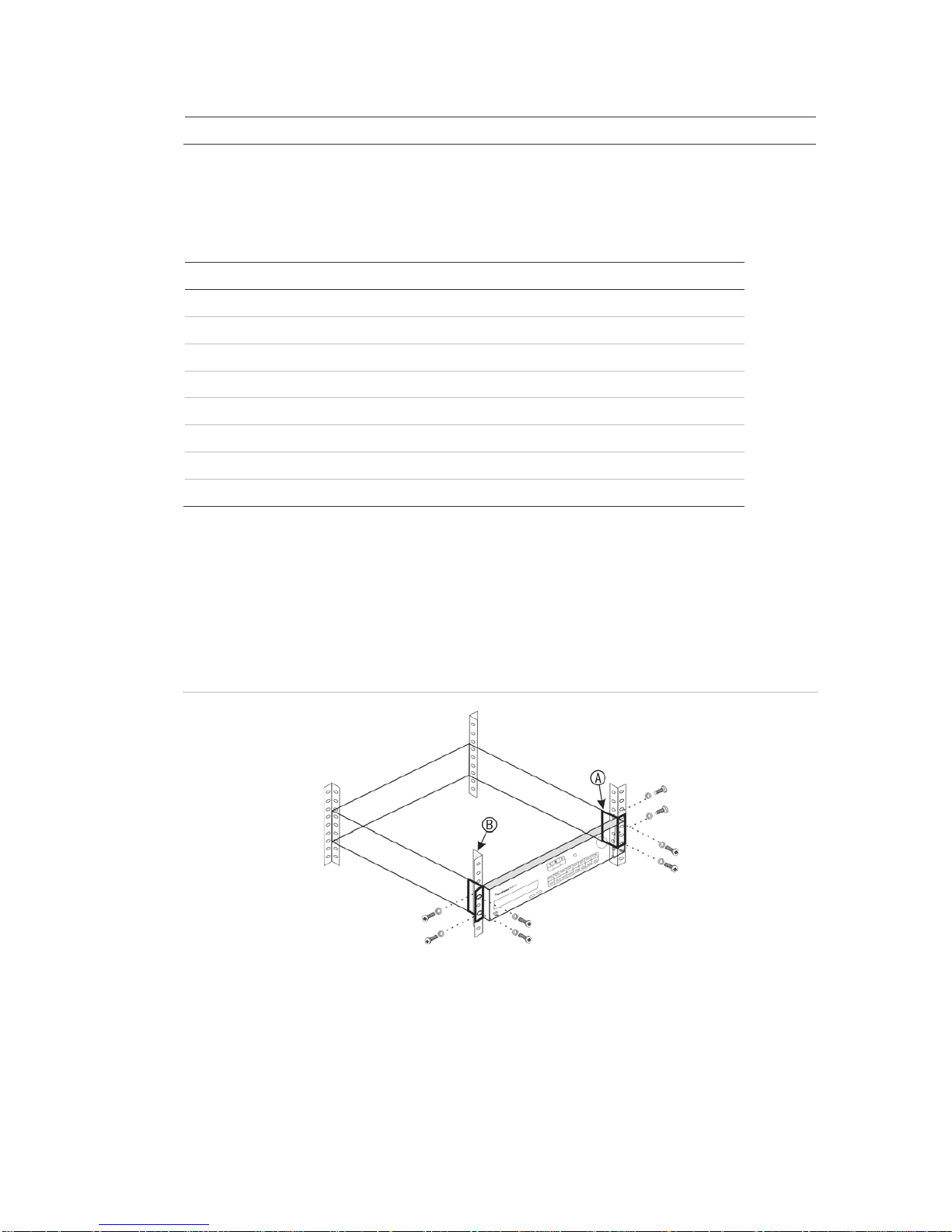
Figure 6: Rack-mount installation
To install the racks:
1. Attach the two small front-rack mount ears (A) to the DVR (supplied).
2. Attach the DVR to the front rails (B) (screws not supplied).

1BChapter 2: Installation
14 TruVision DVR 11 and DVR 11c User Manual

TruVision DVR 11 and DVR 11c User Manual 15
Chapter 3
Getting started
Turning on and off the DVR
Before starting the power up process, connect at least one monitor to the video
out or the VGA interface. Otherwise, you will not be able to see the user interface
and operate the device. Also connect at least one camera.
The DVR auto-detects the video mode (PAL or NTSC) on startup.
It comes equipped with a universal power supply that will auto-sense 110/240 V,
60/50 Hz.
Note: It is recommended that an uninterruptible power supply (UPS) is used in
conjunction with the device.
To turn on the DVR:
Turn on the DVR using the power switch on the back panel. Once it is powered
up, the status LEDs on the front panel will light up. All connected cameras are
displayed on-screen. The DVR automatically begins recording.
To turn off the DVR:
1. In live view mode, right-click the mouse and click Menu. The main menu
window appears.
2. Select the Power Manager icon.
3. In the Shutdown popup menu, select Shutdown. Click Yes to confirm
shutdown.
To reboot the DVR:
1. In live view mode, right-click the mouse and click Menu. The main menu
window appears.
2. Select the Power Manager icon.
3. In the Shutdown popup menu, select Reboot. Click Yes to confirm shutdown.

2BChapter 3: Getting started
16 TruVision DVR 11 and DVR 11c User Manual
Using the setup wizard
Both TVR 11 and TVR11c have an express installation wizard that lets you easily
configure basic DVR settings when first used. It configures all cameras
simultaneously. The configuration can then be customized as required.
By default the setup wizard will start once the DVR has loaded. It will walk you
through some of the more important settings of your DVR.
Any changes you make to a setup configuration page are saved when you exit
the page and return to the main wizard page.
Note: If you want to set up the DVR with default settings only, click Next in each
screen until the end.
To quickly set up the DVR:
1. Connect all the devices required to the back panel of the DVR. See Figure 1
on page 5.
2. Turn on the unit using the power switch on the front panel. After the boot up
screen, the DVR displays video images on screen.
3. Select the preferred language for the system from the dropdown list and then
click Next.
4. Enable or disable the option to start the wizard automatically when the DVR is
turned on. Click Next.
5. Administrator configuration:
Navigate to the Admin Password edit box and click the edit box with the
mouse, or press Enter on the front panel or remote control, to display the
virtual keyboard. Enter the default admin password, 1234.
Note: You must enter an admin password. To change the Admin password,
check New Admin password and enter the new password and confirm it.
Caution: It is strongly recommended that you change the password of the
administrator. Do not leave 1234 as the default password. Write it down in a
safe place so that you do not forget it.
If you should forget the password to your DVR, contact your supplier with the
serial number of your DVR to obtain a secure code to reset it.
Click Next.
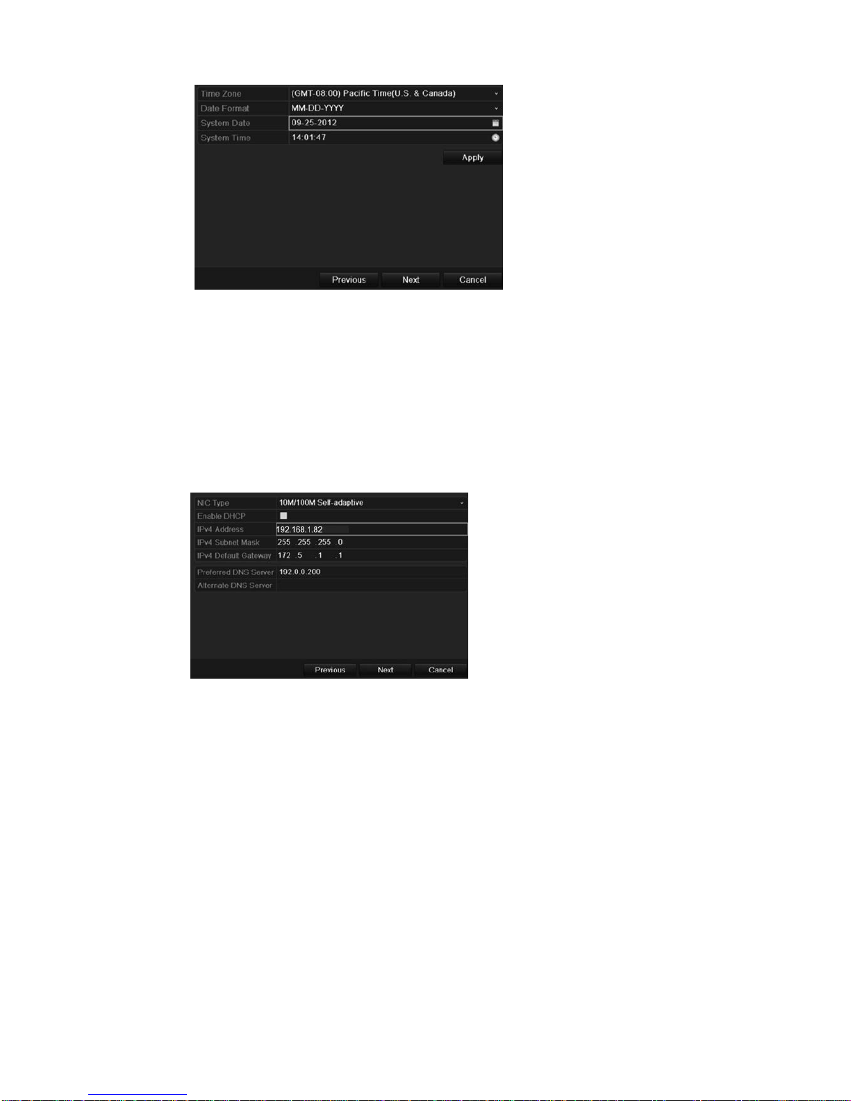
6. Time and date configuration:
Select the desired time zone, date format, system time, and system date.
Note: Daylight savings time (DST) cannot be configured from the Wizard. See
“Configuring time and date” on page 67 for more information on DST.
2BChapter 3: Getting started
TruVision DVR 11 and DVR 11c User Manual 17
Note: The system time and date are visible on screen. However, they do not
appear in recordings.
Click Next to move to the next page, or Previous to return to the previous
page.
7. Network configuration:
Configure your network settings such as the NIC type, IP address, subnet
mask, and default gateway. Enter the preferred DNS server address as well
as the alternate one to use.
Click Next to move to the next page, or Previous to return to the previous
page.
8. HDD management:
Configure your HDD settings as required.
After configuring your HDD settings, click Initialize and Next to move to the
next page, or Previous to return to the previous page.
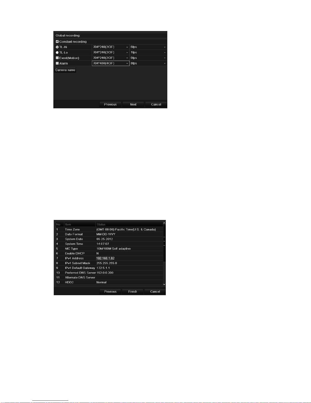
9. Recording configuration:
Configure your recording settings as required. The settings apply to all
cameras connected to the DVR.
2BChapter 3: Getting started
18 TruVision DVR 11 and DVR 11c User Manual
Check the Constant Recording checkbox for the DVR to record continuously
all day. If left unchecked, the DVR will not record.
Check the TL-Hi check box and select its image resolution and frame rate.
Check the TL-Lo check box and select its image resolution and frame rate.
To record motion detection events, check Event (Motion) and select the
image resolution and frame rate.
To record alarm events, check Alarm and select the image resolution and
frame rate.
Under Camera name enter the camera name. A soft keyboard will appear to
enter the characters.
10. When all the required changes have been entered, a page appears showing
all the settings.
Click Finish to exit the Wizard. The DVR is now ready to use.
For a description of the DVR main menu, see “Menu overview” on page 55.

3BChapter 4: Recording
TruVision DVR 11 and DVR 11c User Manual 19
Chapter 4
Recording
This chapter provides instructions on how to define the recording settings of your
DVR. This chapter covers how you can configure your initial recording settings,
schedule recordings, and protect your recorded files.
Enter menu mode by pressing the Menu button on the front panel or use the
mouse menu to select Menu (see “Controlling live view” on page 60 for further
information). See Menu overview on page 55 for a list of the menu icons.
Initializing the recording setting s
Before you can set up your DVR to begin recording, you must first configure
general recording settings for the analog cameras.
Ensure that the HDD has been installed and initialized before configuring the
recording settings. See Chapter 7 “HDD management” on page 45 for more
information.
To configure recording settings:
1. In menu mode, click the Video Schedule icon in the menu toolbar.
2. Select Encoding > Record.
3. Select the camera you want to configure.

3BChapter 4: Recording
20 TruVision DVR 11 and DVR 11c User Manual
4. Configure the following recording settings:
• Encoding parameters: Select one of the stream t y pes: M ain stream (TL-
Hi), Main stream (TL-Lo), Main stream (Event), Main stream (Alarm), or
Substream.
• Stream type: Select the type of stream to record, eit her v ideo or video
and audio.
• Resolution: Select the resolution of the recording. Options include: 4CIF,
2CIF, CIF, and QCIF.
• Bit rate type: Select Constant or Variable.
• Video quality: Select the quality at which to record. If “Constant” was
selected as the bit rate type, this option is unavailable.
• Frame rate: Select the rec or ding frame rate. The options available
depend on the resolution selected. Real time (25 fps PAL/30 fps NTSC) is
only available when the selected resolution is CIF and QCIF.
• Max bit rate mode: Select the general def ault or customized option.
• Max bit rate (kbps): If the customized maximum bit rate mode was
selected, enter the value here. It must be between 32 and 3172 kbps. It is
calculated from the frame rate and time required.
• Pre-record: This is the tim e the camera starts recording before the
scheduled time or event. Select the time in seconds to start pre-recording
before the scheduled time or event.
The maximum pre-recording times available depend on the constant bit
rate. See “Maximum pre-recording times” on page 135 for more
information.
• Post-record: This is the time the camera continues to record af ter the
scheduled time or event. Select the time in seconds to stop post-recording
after the scheduled time or event.
• Auto-delete (day): Select the number of days after which recorded video
from the specified camera is permanently deleted from the HDD. A “day”
is defined as the 24-hour period from when the auto delete mode (ADM)
was set.
The maximum number of days that can be set is 60. However, the actual
number of days permitted depends on the HDD capacity. If the value is set
to ‘0’, the option is disabled.
• Record audio: Select Yes t o r ecord sound wit h t he im ages .
5. Click Apply to save the settings.
6. If you want to save these parameters to another camera, click Copy and
select the camera in the pop-up window that appears. Click OK and return to
the main window.
3BChapter 4: Recording
TruVision DVR 11 and DVR 11c User Manual 21
7. Click the Capture tab and configure the settings for captured video, such as
snapshots. Click Apply to save the settings.
8. Click Back to return to live view.
Defining a recording schedul e
Defining a recording schedule lets you specify when the DVR records video and
under what circumstances. Each camera can be configured to have its own
recording schedule.
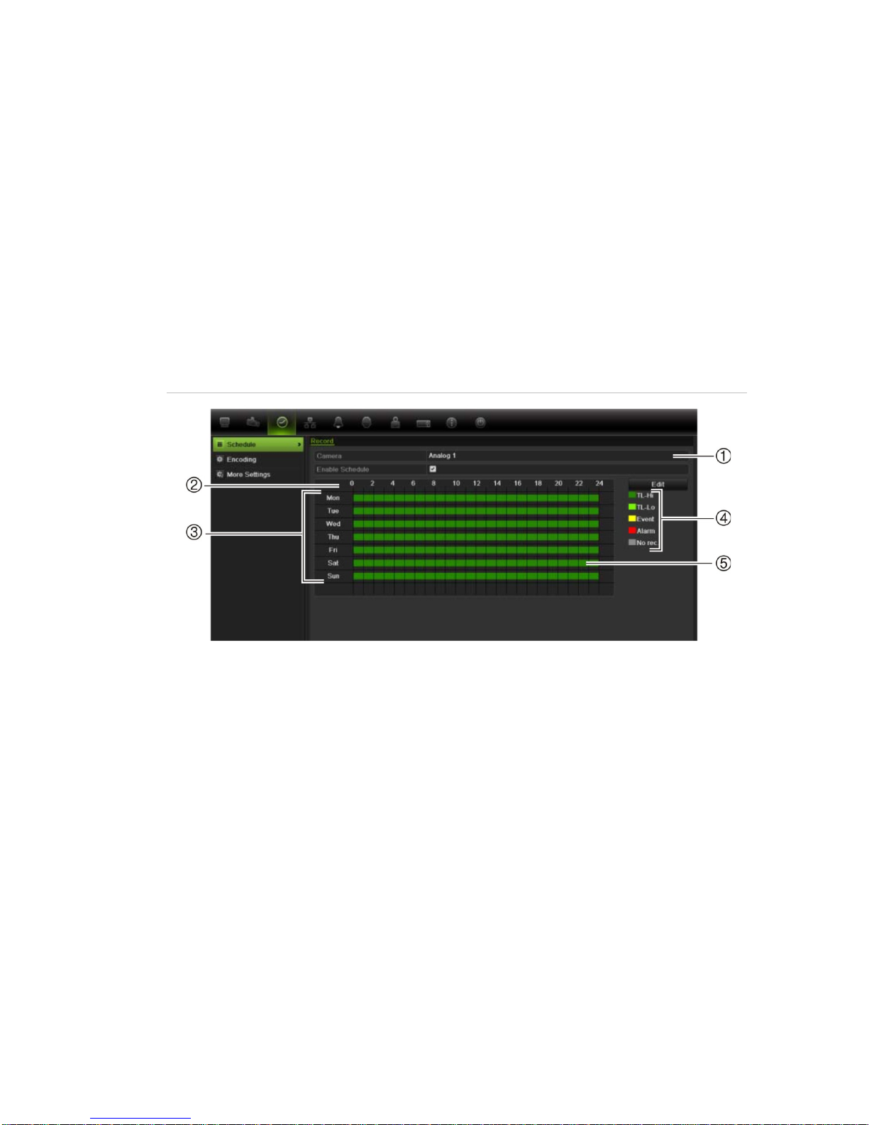
The schedules are visually presented on a map for easy reference. See Figure 7
below for an example.
Figure 7: Description of the schedule window
1. Camera. Select a camera.
2. Schedule time. Represents the 24-hour cycle during which a schedule is selected.
3. Schedule day. There are seven days to select: Sunday (Sun), Monday (Mon), Tuesday
(Tue), Wednesday (Wed), Thursday, (Thu), Friday (Fri), and Saturday (Sat).
4. Recording type. There are five recording types to select, which are color-coded:
TL Time lapse (Green squares): Record of a specific day. Each green square in the timeline
represents an hour in the 24-hour period.
TL-Hi (Dark green): High quality time l apse. Records high quality video.
TL-Lo (Bright green): Low quality time lapse. Records low quality video. This could be used,
for example, for night recordings when few event s or alarms are expected. Saving the
video in low quality helps save resources on the HDD.
Event (Yellow): Records only events, such as motion detection and POS/ATM text insertion.
Alarm (Red): Records only alarms.
None (Grey): No recording during this period.
5. Timeline. There is a 2 4-hour time line for each day. Up to eight recording periods can be
scheduled during the 24-hour period.
3BChapter 4: Recording
22 TruVision DVR 11 and DVR 11c User Manual
Daily schedules
To set up a daily recording schedule:
1. Click the Video Schedule icon in the menu toolbar and select Schedule.
2. Select a camera.
3. Check the Enable Schedule box.
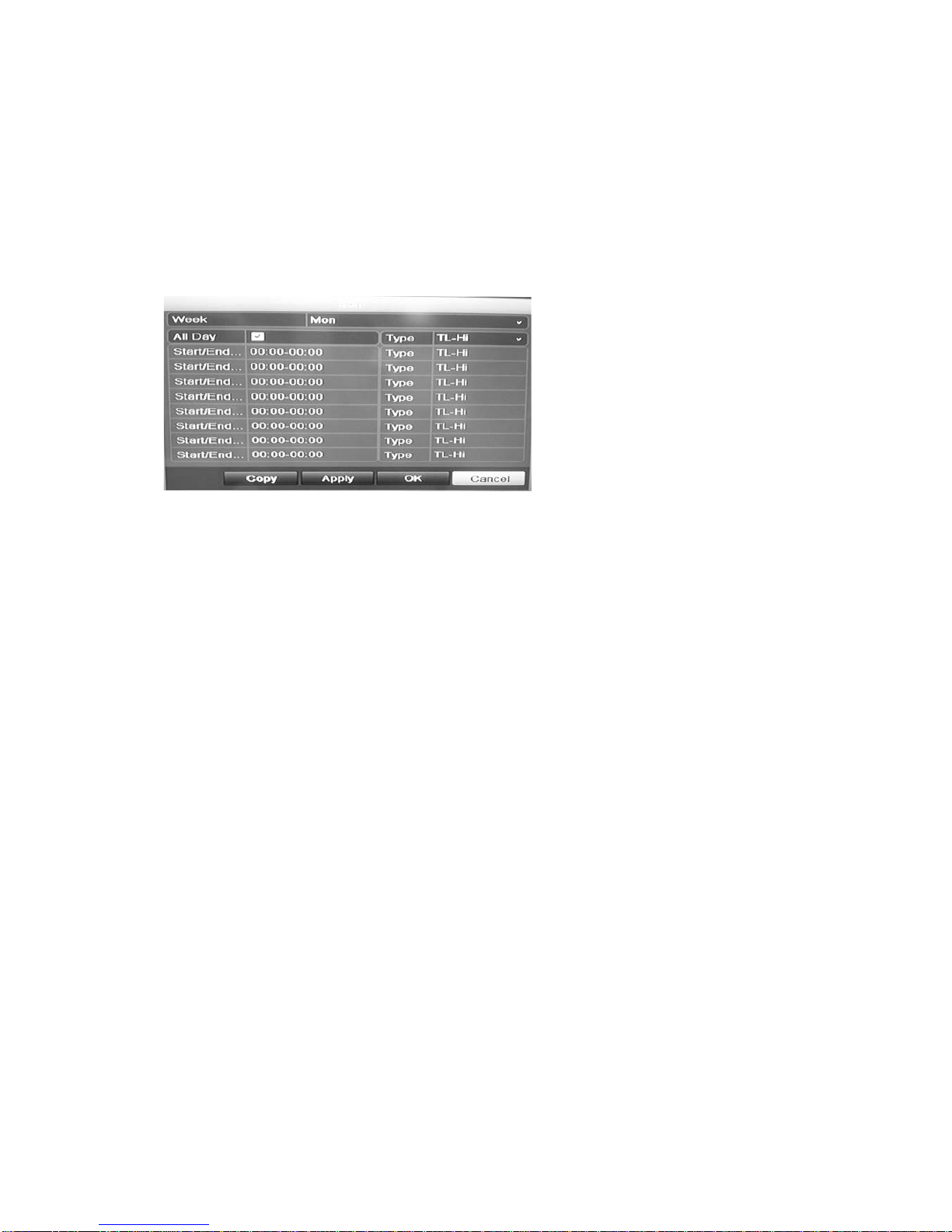
4. Click Edit. The following window is displayed:
5. Select the day of the week for which you want to set up the schedule.
You can define a different schedule for each day of the week.
6. Set the start and end time for recording.
Define a time period by entering a start (left column) and end (right column)
time. You can schedule up to eight time periods. Click All Day to record all
day.
Note: Time periods defined cannot overlap.
7. Select a recording type.
This setting instructs the DVR to begin recording when an alarm is triggered.
The recording type can be based on time and triggered by motion detection
and/or an alarm. If set to TimeLapse (TL-Hi or TL-Lo), the DVR records
continuously.
8. Click Apply to save settings
9. Repeat steps 4 to 8 for other days of the week or to copy the schedule
settings to another day.
To copy the current schedule settings to another day of the week, click Copy.
Select the number of the day of the week to which to copy the schedule. Click
OK to save changes and return to the Edit window.
10. Repeat steps 4 to 9 for other cameras.
11. Click Apply to save the settings and then OK to return to the schedule
window.
3BChapter 4: Recording
TruVision DVR 11 and DVR 11c User Manual 23
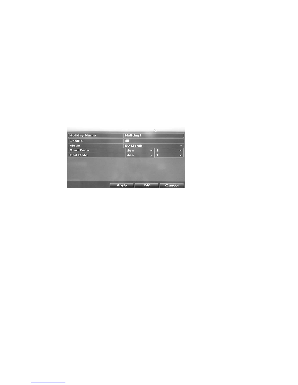
Holiday schedules
As well as being able to schedule when recordings occur during the week, you
can also schedule them for specific holidays in the year such as the first of
January, or the second Wednesday of every month, for example. You can
schedule up to 32 holiday periods.
A holiday period can be scheduled for a particular day or as a block of days.
To set up a holiday recording schedule:
1. Click the Display Mode Settings icon in the menu toolbar and select
Holidays.
2. Select a holiday period from the list and click Edit to modify the settings. The
Edit window appears.
3. Enter the name of the holiday period and click Enable.
4. Select whether the holiday period will be categorized by date, week, or month
and then enter the start and end dates.
5. Click Apply to save the settings and then OK to return to the Edit window.
6. Repeat steps 2 to 5 for other holiday periods.
7. Click Back to return to live view.
Motion detection schedules
You can set up both the schedule and areas sensitive to motion detection for
each camera individually or easily copy the settings of one camera to other
cameras.
For information on scheduling motion detections, see “Motion detection set up”
on page 28.
External alarm schedules
The DVR can be scheduled to record when an alarm is triggered by an external
alarm device such as a PIR detector or dry contacts. For information on
3BChapter 4: Recording
24 TruVision DVR 11 and DVR 11c User Manual
scheduling external alarms, see “Triggering or clearing alarm outputs manually”
on page 32.
Protecting recorded files
There are two methods to prevent recorded files from being inadvertently
overwritten or deleted off the HDD. We highly recommend that important
recorded events be protected from deletion. Recorded files can either be locked
or the HDD that the files reside on can be set to read only.
Locking and unlocking recorded files
Lock files to protect them against being overwritten or deleted.
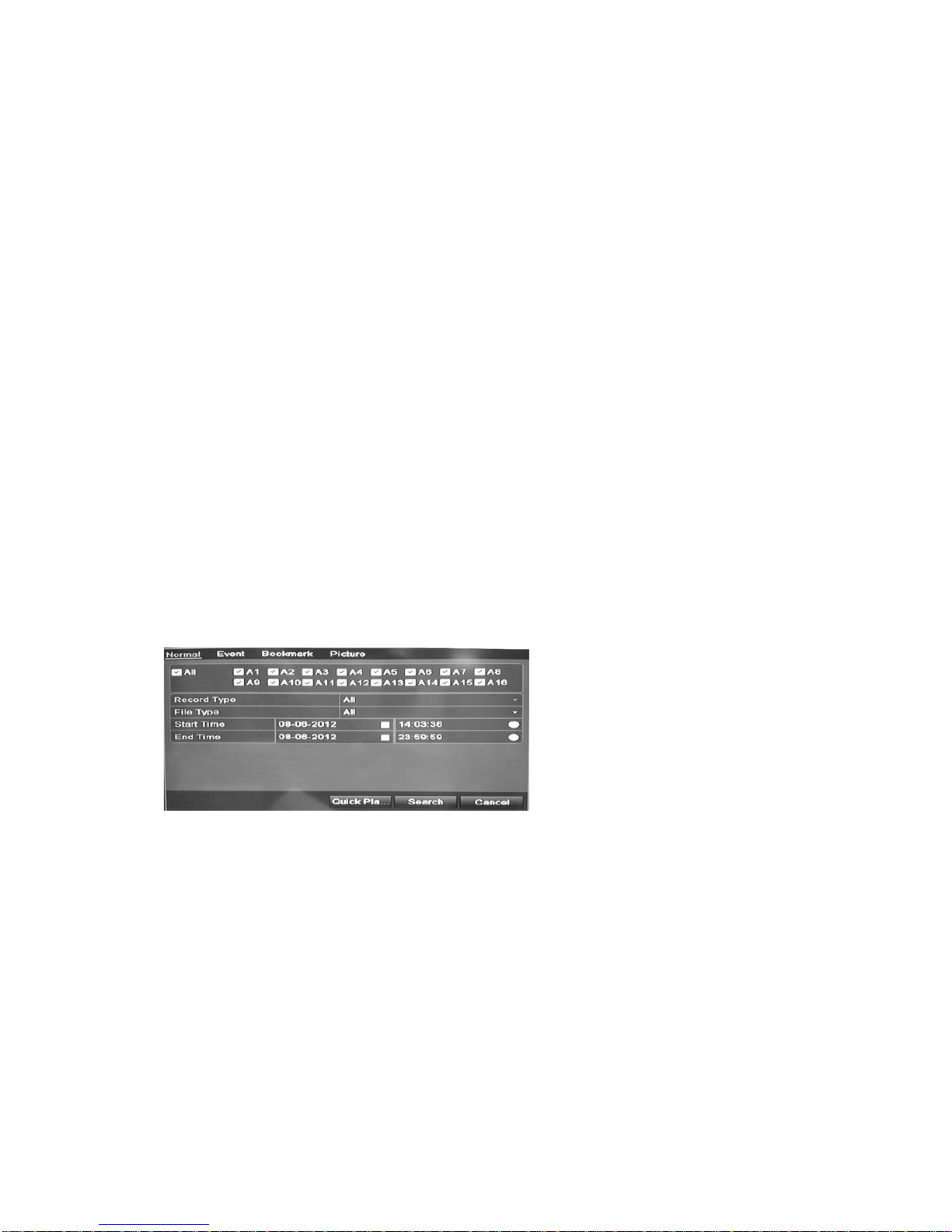
To lock or unlock a recorded file:
1. In live view enter the video search window by pressing the Search but t on on
the front panel or remote control, and then enter Advanced Search.
— Or —
In live view right-click the mouse to display the pop-up menu and select
Advanced Search.
The Search window appears by default for the Normal tab (TVR 11 is shown
below).
2. Search for the desired recording by entering the search parameters, which
include the camera number, record type, file type, and start time and end
time.
3. Click Search.
A list of recordings, similar to the figure below, matching the search
parameters is displayed.
 Loading...