

Page 1

TruVision DVR 10 User
Manual
P/N 1068258 • REV C • ISS 06APR12
Page 2

Copyright
© 201
Disclaimer
The information in this document is subject to change without notice.
(“
specif ically discl ai ms an y li abil i ti es , losses, or ris ks , p ersonal or oth er wise, incurred as a
consequence, dir ectly or indirec t l y, of th e use or application of any of th e c on t ents of t his
document. For the late
www.interlogix.com.
This publication may contain examples of screen captures and reports used in daily
operations. Examples may include fictitious names of individuals and companies. Any
s
Interlogix, TruVision names and logos are trademarks of UTC
Other trade names used in this document may be trademarks or re
the manufacturers or vendors of the r es p ec ti ve products .
UTC Fire & Security Americas Corporation, Inc.
2955 Red Hill Avenue, Costa Mesa, CA 92626
Authorized EU manufacturing representative:
UTC Fire & Securi
Kelvinstraat 7, 6003 DH Weert, The Netherlands
Use this product only for the purpose it was designed for; refer to the data sheet and user
documentation for details. For the latest product information, contact your
visit us on li n e at www .interlog ix.com.
Class B:
digital d evice, purs u ant to part 15 of the FCC ru l es. Th es e limits are d esi gned to provid e
r
residen tial environ m en t . This eq uipment g en er at es ,
energy an d, if not install ed and used in acc or d ance with the ins t ruc tion manual ,
harmful i nterf
Changes or modifications not expressly approved by the party responsible for compliance
could void t h e us er’s authority to operat e th e eq ui pm en t .
2004/108/EC (EMC directive
compli ance with the essential requiremen ts and other rel evan t provisions of Directive
2004/108/EC
2002/96/EC (WEEE directive):
unso
to your loc al su pplier upon th e pur c h as e of equival ent new eq uip m ent, or dispos e of it at
designated collection points. For more information see: www.recyclethis.info.
2006/66/EC (battery directive):
as unsorted municipal waste in the European Union. See the product documentation for
specific battery information. The battery is marked with this symbol, which ma
lettering to indicate cadmium (Cd), lead (Pb), or mercury (Hg). For proper recycling, return
the battery to your supplier or to a designated collection point. For more information see:
www.recyclethis.info.
CAUTION:
of used batt er i es according t o the ins tructions .
www.utcfireandsecurity.com
Trademarks and patents
Manufacturer
Certification
2 UTC Fire & Security. All rights reserved.
UTC Fire & Security.
UTC Fire & Security”) assumes no responsibility for inaccur ac ies or omiss i ons and
st doc u m ent at i on , c ontact your loc al s up pl i er o r visi t us onli ne at
imilarit y t o nam es an d ad dresses of act u al bus i n esses or pers ons is entirely coinc i d ental.
Fire & Security.
gistered trademarks of
-5923, USA
ty B.V.
Intended use
FCC compliance
European Union directives
Contact inform ation
This equipment has been tested and found to comply with the limits for a Class B
easonabl e pr otection ag ains t harmful int er ferenc e when t h e equ ip m ent is operated in a
uses, and can radiate radio frequency
erence to radio communications.
): Hereby, UTC Fire & Security declares that this device is in
Product s m ark ed wit h thi s s ymbol cannot b e dis p os ed of as
rted municipal waste in the European Union. For proper recycling, return this product
This product cont ains a b attery that cannot be disp os ed of
Ther e is risk of explos i on if batteries are replaced by an i ncorrect t yp e. D is p os e
or www.interlogix.com
local supplier or
may cause
y include
Page 3

Content
Chapter 1 Product introduction 1
Product overview 1
Features 1
Chapter 2 Installation 5
Installation environment 5
Unpacking the TVR 10 and its accessories 6
HDD capacity 6
Back panel overview 7
Connection diagram 8
Chapter 3 Operating instructions 9
Control interfaces 9
Controlling the TVR 10 9
Front panel overview 10
Using the mouse 11
Using the IR remote control 13
Using the Web browser 15
Main menu overview 18
Chapter 4 Basic operation 23
Turning on the TVR 10 23
Live mode 23
Connecting the spot monitor 25
Logging on 25
Controlling a PTZ camera 26
Manual recording 28
Playing back video 30
Archiving recorded files 35
Turning off the TVR 10 37
Chapter 5 Advanced setup 39
User settings 39
Camera settings 45
Display settings 57
Recording settings 61
Alarm settings 65
Network settings 70
PTZ settings 74
TruVision DVR 10 User Manual i
Page 4

Chapter 6 Utilities settings 81
Modifying the device name 81
Restoring to factory defaults 82
Managing the hard drive 83
Acknowledging an alarm 84
Rebooting the TVR 10 84
Viewing logs 84
Chapter 7 Upgrading the firmware 87
Upgrade methods 87
Upgrading with a USB flash memory 87
Upgrading through the Web browser 88
Setting up the wftp32 FTP server 89
Upgrading using the FTP server 89
Appendix A Mouse control function 91
Display interface 91
PTZ interface 91
Camera name position configure interface 92
Area configure interface 92
Text input interface 92
Playlist interface 93
User interface 93
Appendix B Specifications 95
Appendix C Troubleshooting 97
Appendix D PTZ protocols 99
Appendix E Factory defaults 100
Menu defaults 100
Network defaults 100
Index 103
ii TruVision DVR 10 User Manual
Page 5

Chapter 1
Product int roducti on
Product overview
This is the TruVision DVR 10 User Manual for models:
• TVR-1004-250
• TVR-1004-500
• TVR-1004-1T
The TruVision DVR 10 (TVR 10) is a network digital video record er deve loped for
digital surveillance. The TVR 10 uses an embedded microcontroller unit with the
Linux operating system, combining the most advanced technology in video and
audio encoding/decoding, hard drive recording, and TCP/IP communication. The
TVR 10’s firmware is stored directly into the memory, making it more stable and
reliable.
The TVR 10 includes the features of both a digital video recorder (DVR) and
digital video server ( DVS). The device can be used as a standalone system or to
build a surveillance network such as those widely used in the retail, education,
banking, telecommunications, transportation, manufacturing, warehouse, and
irrigation industries.
Features
This section describes the available TruVision DVR 10 features.
Compression
The TVR 10 supports the following video features:
• H.264 video compression algorithm and each channel can be CIF real-time
(PAL: 25FPS, NTSC: 30FPS), 4CIF, DCIF, 2CIF, QCIF
TruVision DVR 10 User Manual 1
Page 6

Chapter 1: Product introduction
• Multiple area motion detection
• Privacy masking
• Tampering alarm view
• Video signal loss alarm
• Changeable OSD position
• Both variable and constant bit rate
• Dual-stream, and the substream can support CIF/QCIF resolution
Storage
The TVR 10 supports the following storage features:
• One SATA interface and HDD up to 1 TB memory
• HDD S.M.A.R.T. technology
• FAT32 file system
• Multiple record modes: schedule record, motion detection record, external
alarm record, motion and alarm record, motion or alarm record, manual
record
• Overwrite and nonoverwrite record mode
• USB flash drive, USB hard drive, and USB CD-RW/DVD-RW to backup
Preview and playback
The TVR 10 supports the following preview and playback features:
• One main composite video output (for monitor A) and an additional composite
video output (for monitor B)
• One VGA output with 1024 x 768 resolution
Note: VGA has precedence over the main composite video output and both
cannot be used at the same time.
• Play forward, backward, pause, frame-by-frame, etc.
• User-defined preview layout
• One playback channel
Network
The TVR 10 supports the following network features:
• TCP, UDP, Multicast, DHCP, etc.
• RTP
2 TruVision DVR 10 User Manual
Page 7

Chapter 1: Product intr oduct ion
• ADSL (PPPoE) dialup function
• Programming and setup through browser interface
• Remote download and playback the recorded files
• Remote upgrade of TVR 10 firmware
• PTZ control using Web browser
• IE for network control
• Remote access to log file
Other features
The TVR 10 supports the following additional features:
• Bidirectional audio
• Watermarks
• Local and remote PTZ control
• Multilevel user management
• Local and remote log searching function
TruVision DVR 10 User Manual 3
Page 8

Page 9

Chapter 2
Installation
Installa tion environment
When installing your product, consider these factors:
• Ventilation
• Temperature
• Moisture
• Chassis load
Ventilation: Do not block any ventilation openings. Install in accordance with the
manufacturer’s instructions. Ensure that the location planned for the installation
of the unit is well ventilated.
Temperature: Consider the TVR 10’s operating temperature (14 to 122°F, −10
to 50°C) and noncondensing humidity specifications (10 to 90%) before choosing
an installation location. Extremes of heat or cold beyond the specified operating
temperature limits may reduce the life expectancy of the TVR 10. Do not install
the TVR 10 on top of other hot equipment. Leave 1.75 in. (44 mm) of space
between rack mounted TVR 10 units.
Moisture: Do not use the unit near water. Moisture can damage the internal
components. To reduce the risk of fire or electric shock, do not expose this unit to
rain or moisture.
Chassis: Equipment weighing less than 35 lb. (15.9 kg) may be placed on top of
the TVR 10.
TruVision DVR 10 User Manual 5
Page 10

Chapter 2: Installation
Model number
TVR
TVR
TVR
Unpacking the TVR 10 and its accessories
When you receive the product, check the package and contents for damage, and
verify that all items are included. There is an item list included in the package. If
any of the items are damaged or missing, please contact your local supplier.
Items shipped with the product include:
• IR (infrared) remote control
• Two AAA batteries for the remote control
• USB mouse
• Power supply
• AC power cord
• TruVision DVR 10 Quick Start Guide
• TruVision DVR 10 User Manual (on CD)
HDD capacity
Storage capacity for the TruVision DVR 10 varies depending on the model. Refer
to Table 1 below for more information.
Table 1: TruVision DVR 10 model types
Description
-1004-250 TruVision DVR Model 10, 4 ch, 250 GB
-1004-500 TruVision DVR Model 10, 4 ch, 500 GB
-1004-1T TruVision DVR Model 10, 4 ch, 1 TB
6 TruVision DVR 10 User Manual
Page 11
Chapter 2: Installation
1 3
42
VIN VOUT
1
2
AIN AOUT
ETHERNET
VGA
RS-485
ALARM IN
OUT
POWER
+12V
T+T-R+R-
1 G
1234GG
1 2 3 4
5 6
7 8
9 10 1211
1.
2.
3.
4.
5.
6. Powe r switch
7.
8.
9.
10.
11.
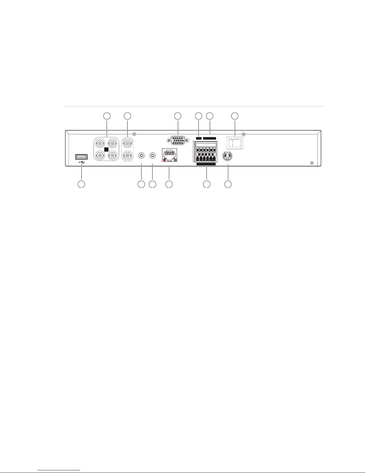
12. +12 VDC power supply input
Back panel overview
Figure 1 below shows the back panel controls and connectors on a typical
TruVision series network digital video recorder. Details may vary for specific
models.
Figure 1: Back panel
Video in
Video ou t
VGA interface
Alarm out
RS-485 T+ T− R+ R−
USB interface
Audio in
Audi o out
Ethernet port
Al arm i n
TruVision DVR 10 User Manual 7
Page 12
Chapter 2: Installation
1 3
42
VIN VOUT
1
2
AIN AOUT
ETHERNET
VGA
RS-485
ALARM IN
OUT
POWER
+12V
T+T-R+R-1 G
1234GG
Power
Link/Act
100
FD/Col
1 2 3 4 5 6 7 8
1. Connect up to four cameras
2.
3.
4.
5.
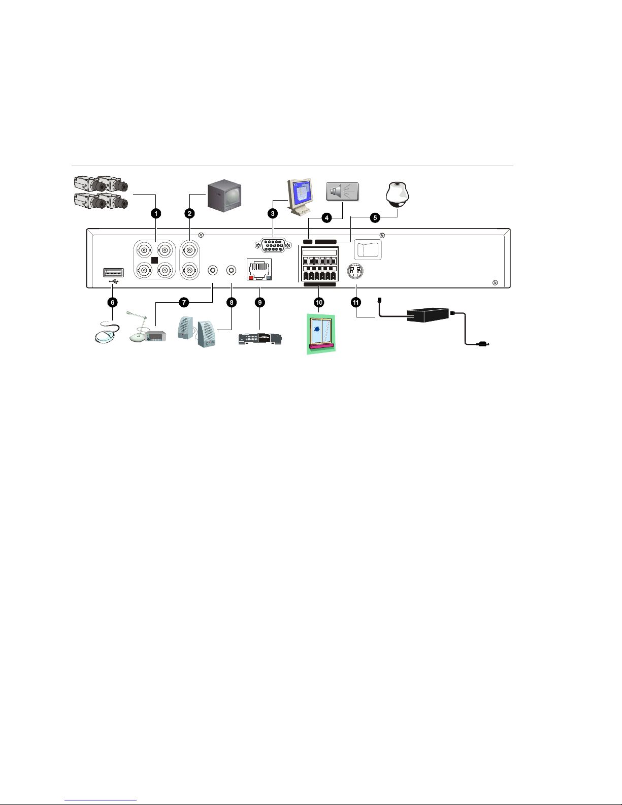
6. Con nect to a U SB m ouse
7.
8.
9.
10.
11. Connect to the power supply
Connection diagram
Use Figure 2 below as a visual guide to connect the various peripherals to the
TVR 10.
Figure 2: Rear panel connection diagram
Connect up to two CCTV monitors (one for main,
two for spot)
Conn ect t o a VGA monitor
Alarm output
Connect to a PTZ control
Connect t o audio input
Connect to speakers
C onn ect t o network d e v ic es
Connect to alarm input cables
8 TruVision DVR 10 User Manual
Page 13

Chapter 3
Operating instructions
Control interfaces
The TVR 10 has three control interfaces:
• Built-in interface
• Display interface
• Web browser interface
Built-in interface. The built-in interface is displayed on the VBA monitor. It
consists of a main menu and several dialog screens that let you configure and
control the device. You can invoke the built-in interface using the front panel,
remote control, or mouse.
Display interface. The display interface consists of various toolboxes that
appear on top of the VBA monitor image. These let you control live or playback
video while in PTZ or playback mode. You can invoke the display interface from
the built-in interface screens or from the mouse menu. The controls in any
toolbox can be operated using the front panel, remote control, and mouse.
Web browser. The Web browser interface uses Internet Explorer to simulate the
display and control functions of the VGA monitor on a remote PC. The Web
browser interface can only be invoked by a PC with Internet access.
Controlling the TVR 10
You can control the TVR 10 using:
• Front panel control
• IR remote control
• Mouse control
TruVision DVR 10 User Manual 9
Page 14
Chapter 3: Operating instructions
Item
1
Blinking red i ndic ates that video is being recorded. Solid red
2
3
4
1
MENU
Disp
Srch
PTZ
Live
Rec
Esc
Power
HDD
Tx/Rx
TVR10
2
1
3
2
3
41MENU
Disp
Srch
PTZ
Live
RecEsc
Power
HDD
Tx/Rx
TVR10
2
1 3
Front panel control. Use the directional arrow buttons to select a command,
option, or button on a screen. Use the ENTER button to confirm a selection.
IR remote control. Use the directional arrow buttons to select a command,
option, or button on a screen. Use the OK button to confirm a selection.
Mouse. Move the pointer to a command, option, or button on a screen. Click
(with the left mouse button) to confirm a selection.
You can use your preferred control method for any procedure, but in most cases
we describe procedures using mouse terminology. Optional control methods are
given only when they differ substantially from mouse control methods.
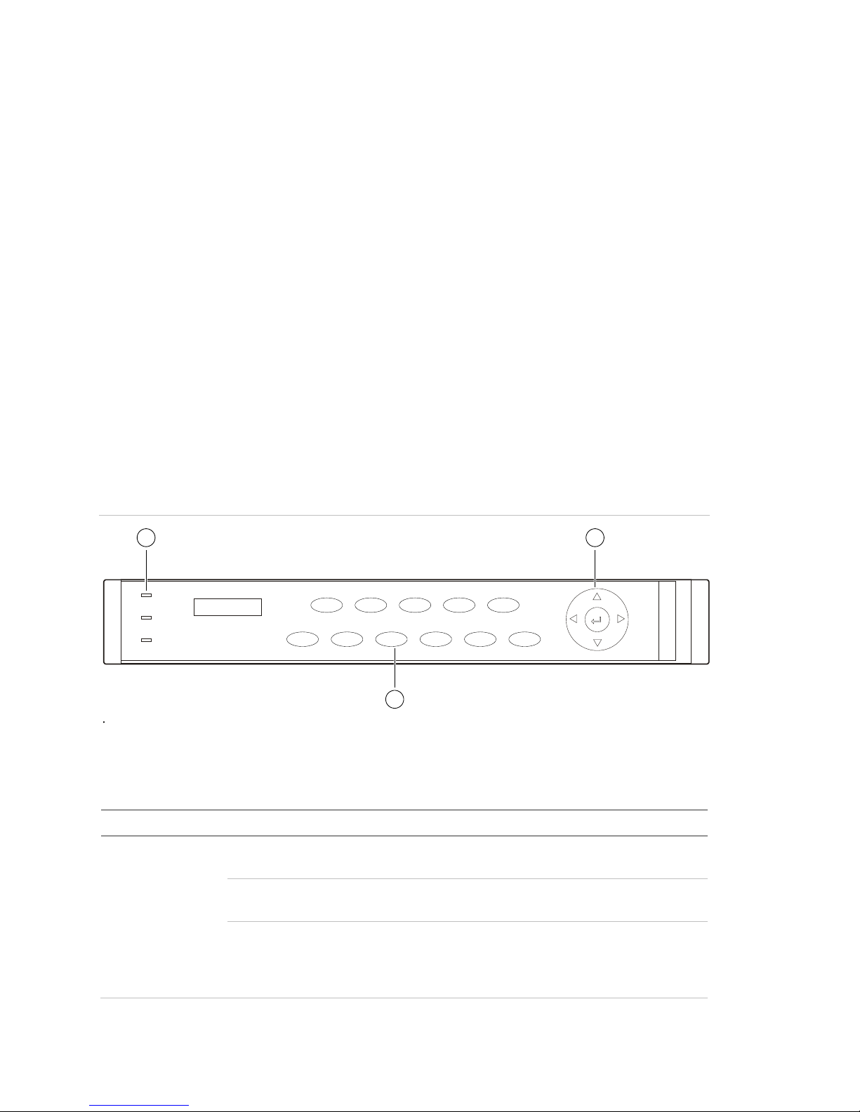
Front panel overview
The buttons on the front panel control all DVR functions. The LED indicators light
up or flash to alert you of various conditions. See Table 2 below for more
information.
Figure 3: Front panel introduction
Table 2: Fr ont panel legend
Type Name Description
Status
LEDs
HDD
Power Green indicat es the DV R is working. No light indicates the
DVR is powered off.
indicates that the hard drive has an error.
Tx/Rx Solid green indic ates that the DVR is being accessed by
Internet Ex plor er or Cli ent Soft ware. B linking green
indicates that data is being transferred between the DVR
and Internet Ex plor er or Cli ent Soft ware.
10 TruVision DVR 10 User Manual
Page 15

Chapter 3: Op erating instruc tions
Item
2
3
to select
Type Name Description
Numeric
buttons
MENU Switches out of di spl ay mode to display the main menu.
Function
buttons
SRCH Displays the Search screen t o search for and play back
REC Displays the Manual Record screen and options.
PTZ Enters PTZ control m ode.
DISP Multiple screens display .
LIVE Displays Camera 1 in liv e mode.
Directiona
l controls
ENTER
1 to 4 Enter numbers from 1 to 4.
ESC Cancels the current c hanges and ret ur ns to the previous
screen or main menu.
recorded video.
Switch from the main menu to live mode.
, , ,
(arrow
buttons)
(central
button)
In menu mode, use the Left or Right Ar r ow butt ons
and the Up or Down Arrow buttons to edit .
PTZ direction cont r ol.
Playback speed contr ol.
Confirms menu selections.
Enters or × to enable or disable options.
Pauses playback.
Using the mouse
Use the USB mouse provided with the TVR 10 to carry out the same oper ations
as the front panel and remote control. The USB mouse lets you navigate and
make changes to settings in the user interface.
Connect the mouse to the TVR 10 by plugging the mouse USB connector into
the USB port on the back panel. The mouse is immediately operational. You can
replace the standard mouse with a wireless mouse. However, the unit may not
support all types of wireless mouse.
To use the mouse in live view:
1. Scroll forward and backward between cameras.
When in full-screen view, use the scroll button on the mouse to scroll forward
and backward through the cameras.
2. Double-click to toggle between full-screen and multiview.
When in multiview, double-click a camera to display its image in full-screen
view. Double-click again to return to multiview.
TruVision DVR 10 User Manual 11
Page 16
Chapter 3: Operating instructions
Command
Main Menu
Camera
Multi
screen
PTZ Control
Search
Manual Record
Open/Close Status
Spot Channel
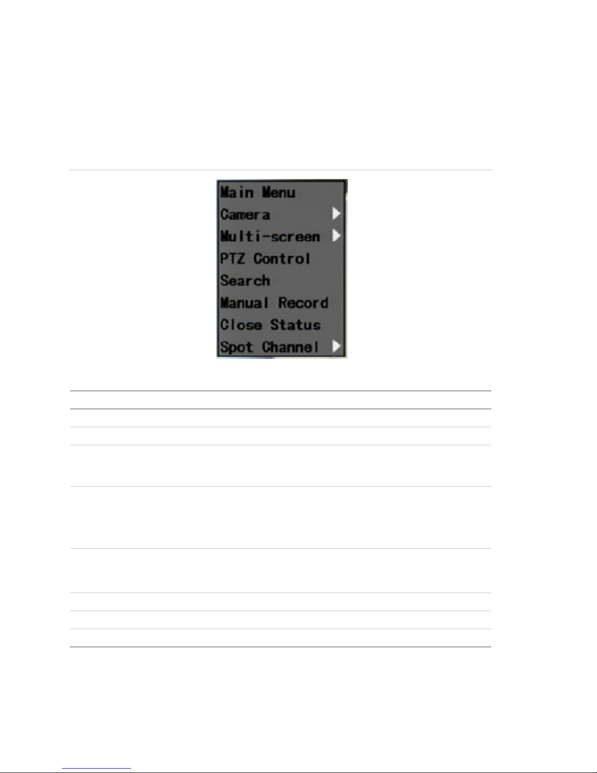
Mouse shortcut menu
To display the mouse control menu, right-click while in live view. The commands
on this shortcut menu are shown in Figure 4 below. Table 3 below describes the
commands.
Figure 4: Mouse shortcut menu
Table 3: Mouse shortcut menu commands
Description
Displays the main menu.
Selects an indiv idual c am er a.
-screen Selects multiview. The multiv iew options vary based on the number of
cameras connected to the TVR 10. You can choose either a fouror single screen displ ay .
Contr ols a PTZ camera. Right-click to view the following options:
Channel: Sel ects the c am er a to control
Preset: Selects a preset number to use
Exit: Returns to di spl ay mode
Displays the Pl ay Back screen. Lets you search for recordings using
specific crit eri a such as by camer a, type of event, time, and text.
Right-click to return to display mode.
Displays the Manual Recor d screen.
Toggles the on-screen status bar on and off.
Controls the spot monitor.
12 TruVision DVR 10 User Manual
Page 17
Chapter 3: Op erating instruc tions
Item
1
2
3
4
5
6
7
8
9
3
6
9
1
4
7
2
5
8
0
POWER
ABC
DEF
GHI JKL MNO
PQRS TUV WXYZ
OK
INFO
PTZ
ESC MENU
+
-
F
O
C
U
S
+
-
PLAY REC VOIP/MON PREV
DEL
#
1
2
3
4
5
6
7
8
9
10
15
14
13
12
11
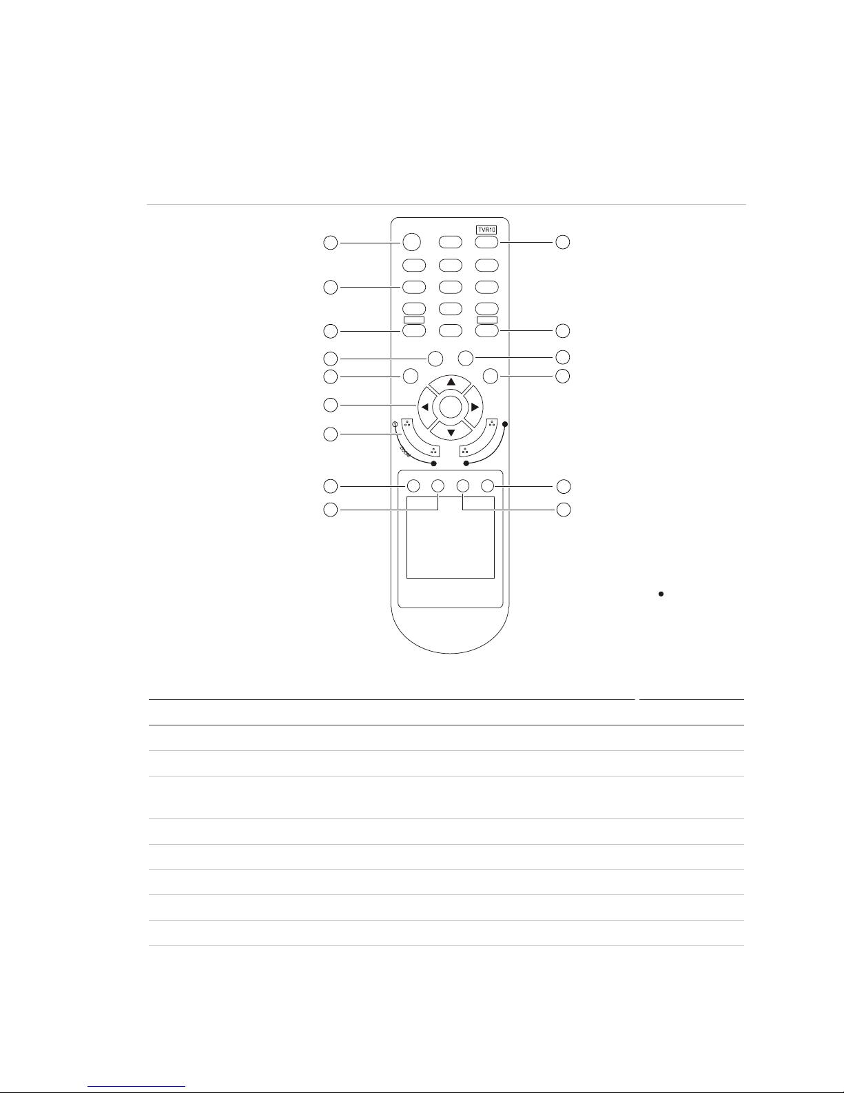
Using the IR rem o te control
Use the IR remote control to carry out functions similar to the front panel buttons.
Figure 5: Controls on the IR remote
Table 4: IR remote control legend
Name Description
POWER Turns off t he devic e.
TVR 10 Enables the IR remote control to control the TVR 10.
Numeric butt ons Enter numbers, lower case or upper case letters, and
DEL Deletes an entry in edit m ode.
# Toggles between video inputs or video channels.
INFO Reserved for future use.
ESC Cancels and returns to the m ain m enu.
PTZ Enters PT Z control mode.
sym bols in edit mode.
MENU Switches from live mode to menu mode and displays the
main menu.
TruVision DVR 10 User Manual 13
Page 18

Chapter 3: Operating instructions
Item
10
commands or options; t he Up or Down Arrow buttons edit or
11
12
13
14
15
Name Description
, , , (arrow
buttons)
OK (central butt on)
Lens control FOCUS and ZOOM cont r ol for c am er a lens.
SRCH Displays the Search screen to search for and play back
REC Displays the Manual Record screen.
DISP Displays multi screen. Switches to live mode.
LIVE Displays Camera 1 in liv e mode.
In menu mode, the Left or Right Arr ow butt ons select
select values. OK enters the selection or value.
PTZ direction control.
Playback speed contr ol.
recorded video.
To place batteries into the IR remote control:
1. Remove the battery cover.
2. Insert the batteries. Make sure that the positive (+) and negative (−) poles are
correctly placed.
3. Replace the battery cover.
To connect the remote control to the TVR 10:
1. Turn on the TVR 10 and wait for the live video to appear.
2. On the remote control, press and release the Power button. The remote
control is now operational.
To turn off the IR remote control:
1. Press the TVR 10 button while the IR remote control is still controlling the
TVR 10.
To turn the TVR 10 off with the remote control:
1. Press and hold the POWER button for several seconds. A power off prompt
displays.
2. Enter a password, if requir ed.
3. Select Confirm then switch off the manual power located on the back panel.
Troubleshooting the remote control
If the IR remote control is not functioning properly, perform the following tests:
• Check the battery polarity.
14 TruVision DVR 10 User Manual
Page 19
Chapter 3: Op erating instruc tions
Item
1
2
3
4
a to set
• Check the remaining charge in the batteries.
• Check that the IR remote control sensor is not masked.
If the problem still exists, please contact your administrator.
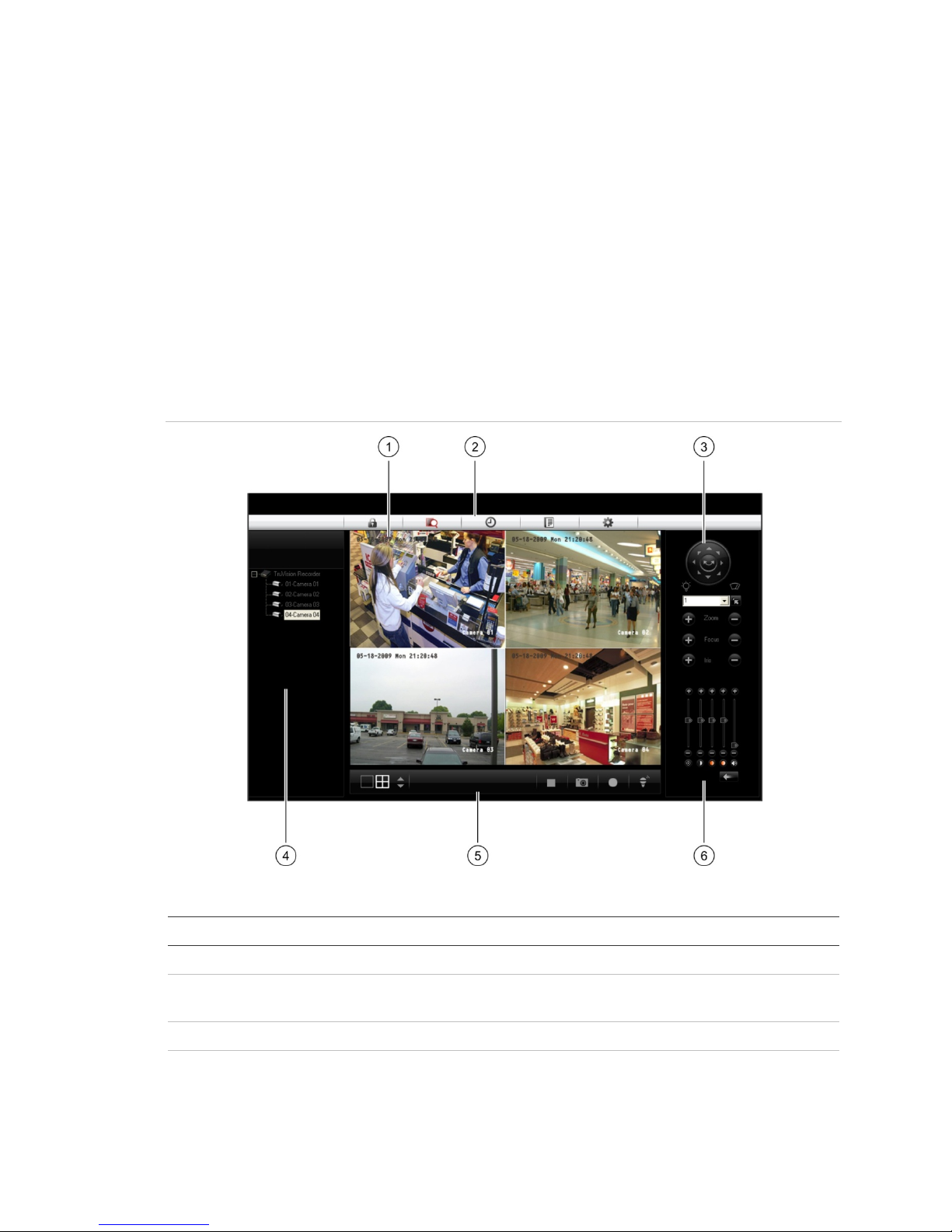
Using the Web browser
The TVR 10 Web browser lets you view, record, and play back videos as well as
manage all aspects of the TVR 10 from any PC connected to your network. The
browser’s easy-to-use controls give you quick access to all TVR 10 functions.
Figure 6: TVR 10 Web browser
Table 5: Web browser interface layout
Name Description
Viewer View live or playback vi deo.
Navigati on bar Logs you out of the interface. Accesses live or playback video.
PTZ control Controls the PTZ functions of camera in live mode.
Navigator View video of the selected camera. Right-click the camer
TruVision DVR 10 User Manual 15
Displays the TVR 10 logs. Configures the unit remotely.
the viewing stream type (main stream or sub-stream).
Page 20

Chapter 3: Operating instructions
Item
5
microphone to a speaker connect ed to the TVR 10 (bidirectional
6
Name Description
Taskbar Displays singl e or four-screen views. Selects multi screen.
Captures screen. Arc hives video. Lets you talk through a
audio).
Video adjust Adjusts video image such as brightness, saturation, hue, and
audio volume. Restores default settings.
To access the TVR 10, open a Web browser and enter the IP address assigned
to the TVR 10 as a Web address. In the login screen, enter the default user ID
and password.
User ID: admin
Password: 1234
The Web browser uses the following ports:
Video Port: 8000
HTTP Port: 80
Searching recorded video for playback
To search for recorded video for playback, click the Playback button on the
navigation bar. The Search screen displays. Select a play type and a file type in
the appropriate boxes and specify a time range. Click the Search button
(displayed as a magnifying glass) to start your search.
Search results display below your specified search criteria and are arranged by
start time. Double-click a result item to play back video.
Playing back recorded video
Use the playback control bar, shown in Figure 7 below, to control playback video.
The playback control bar lets you do the following:
• Control playback speed (fast forward, slow forward, and stop)
• Capture a screen image of the playback video
• Save a video segment onto your desktop
• Download recorded video to your hard drive
Figure 7: Playback control bar
16 TruVision DVR 10 User Manual
Page 21

Chapter 3: Op erating instruc tions
To quickly archive a segment of a video you are playing back, click the Save
button to begin archiving and click again to stop archiving. The resulting video file
is saved on your desktop.
Click the Download button to download that video file into your hard drive.
Viewing logs
To view logs using the Web browser interface, click the Log button on the
navigation bar. The Log screen displays. Use the filter boxes, located on the right
of the screen, to narrow the list of logs by defining the event type and date range.
Click the Search button (displayed as a magnifying glass) to begin your search.
Use the Save button, located at the bottom right of the screen, to save the log
files on your hard drive.
Using the Web browser to configure the device
The Web browser lets you to configure the TVR 10 remotely using your PC. Click
the Configure button to display the Remote Configuration screen. This screen
lets you configure the server, network, cameras, alarms, and upgrade the
firmware.
Setting the stream type
Video stream refers to the flow of network data between the device and the Web
browser interface. The higher the stream type specified in the Web browser, the
higher the video quality being viewed and recorded. When viewing video in a
four-screen layout, data is being transferred into four different streams, which can
overload a system with low bandwidth. We strongly recommend that you set your
stream type to Sub-stream to avoid overloading your network.
To configure the stream type to sub-stream:
1. Click Configure on the navigation bar to display the Remote Configuration
screen.
2. Click the Channel Configuration tab.
3. Select Sub-stream in the Type box.
4. Change the appropriate video quality settings.
Note: We recommend that you do not change the frame type and iframe.
5. Click Save to save your changes.
TruVision DVR 10 User Manual 17
Page 22
Chapter 3: Operating instructions
Viewing video in sub-stream
To view video in sub-stream, right-click a camera in the Navigator and select
Sub-stream. The camera displays video in sub-stream.
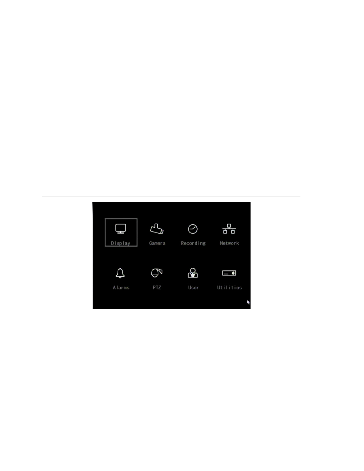
Main menu overview
The built-in interface includes a main menu with eight command buttons. Each
command displays a screen that lets you edit a group of TVR 10 settings. The
main menu is shown in Figure 8 below. Access to different option screens varies
depending on your access privileges. Most screens are available only to system
administrators.
The white frame surrounding a command button or option shows that the item is
currently selected.
Figure 8: Main menu
Main menu commands options
Table 6 on page 19 provides a list of controls and options availab le on each
screen that you can access from the main menu.
18 TruVision DVR 10 User Manual
Page 23

Chapter 3: Op erating instruc tions
Main menu
command
Display
Recording
Alarms
User
Table 6: Menu commands and screen options
Dialog scr e e n options Main menu
Device ID
Require password
Menu timeout
Video standard
Enable scaler
Menu transparency
Date and Time
Multi-Screen
Recor d mode
Camera
Stream type
Resolution
Frame rate
Bit rate
Record schedule
Pre-event time
Post-event time
Copy to camera
Alarm input
Input type
Alarm handli ng, policy, and
PTZ linkage
Alarm rules / PTZ
Copy to alarm in
Alarm out
Duration
Alarm out time
Copy to alarm out
Notifications
Dialog scr e e n options
command
Camera Camera
Camera title position
Adjust video
Time and date display
Motion detection
Advanced settings
Copy to camera
Network IP address
Subnet mask
Gateway
Port
HTTP port
Advanced settings
PPPoE
DDNS
PTZ Camera
Baud rate
Data bits
Stop bits
Parity
Flow control
Protocol
PTZ address
Preset
Preset tour
Shadow tour
Copy to camera
Add/Delete
Password/Verify
Default priv ileges
Set Privil eges
Using the main menu
Click a command on the main menu to display the related screen. Alternatively,
you can use the Up or Down Arrow buttons to select a menu co mmand or screen
option, and then press the ENTER or OK button to confirm the selection.
TruVision DVR 10 User Manual 19
Utilities System information
View log
Alarm output
Hard disk
Firmware upgrade
Factory defaul ts
Reboot
Power off
Page 24

Chapter 3: Operating instructions
Button
MENU
SRCH
REC
PTZ
Table 7 below shows the front panel buttons you can use to display the main
menu or various dialog screens.
Table 7: Main menu display
Action
Di spl ay the TVR 10 main menu
Display the Play Back screen
Display the Manual Rec or d screen
Display the PTZ interface
Note: You must enter a user name and password to display the main menu. The
default user name is “admin” with a password of “1234”.
Navigating through dialog screens
Each dialog screen includes various options and buttons as seen in Figure 9
below. The frame surrounding an option or button indicates that this option is
currently selected.
Use the mouse to select any option or button on the screen. You can also use
the directional arrow buttons (Up, Down, Left, or Right) to navigate through the
options. Changes to screen settings can be entered in various ways as shown in
Table 8 on page 21.
Figure 9: Camera input adjustment
20 TruVision DVR 10 User Manual
Page 25

Chapter 3: Op erating instruc tions
Control
Check box
List box
Provides more than two values for the option. Only one of them can be selected.
Edit box
Command
button
that are unavail able ar e displ ay ed in gray. They must be enabled before you can
Table 8: Types of control on the screen
Description
Provides two values: indicates enabled and × indicates disabl ed. You can
click the check box or use the ENTER or OK button to switch between values.
Click the scroll arr ows at the right-hand side of the box to scroll through t he
possible values. You can also use the Up or Down Arrow buttons to select a
value. For example, t he Cam er a option is a list box that lets you select the
camera you want to work with.
Lets you enter character s. For more information, see “Using an edit box” below.
Triggers a special f unc tion or lets you display another screen. For example, click
the Rules button t o displ ay the Rules screen. Click the Confirm button to sav e
your settings and ret ur n to the main menu. Click the Cancel button to abandon
any changes made on the screen and ret ur n to main menu. Command buttons
click them.
Using an edit box
An edit box lets you type characters to set the value of an option, such as a
camera name. You must be in edit mode before you can enter a value.
Note: A full range of alphanumeric characters is only available when using the
mouse or remote control.
To enter text in an edit box using the mouse:
1. Click anywhere within the edit box to enter the edit mode and display a virtual
keyboard.
2. Click to enter the desired characters into the edit box.
3. When you’re finished, click the edit box to accept the value you’ve entered.
To enter text in an edit box using the remote control:
1. Press OK to enter the edit mode.
2. Press # to select the format and type of character you want to enter.
While in edit mode, the status bar on the bottom left of the screen displays
which type of character will be entered. For exampl e, the figure below
indicates that characters will be entered in uppercase.
Options include number, uppercase, lowercase, or symbols. There are 24
different symbols to select. Press 0 to scroll between four pages of symbols.
3. Enter your characters.
TruVision DVR 10 User Manual 21
Page 26

Chapter 3: Operating instructions
Use the numeric buttons on the remote control to enter characters. Press the
numeric buttons repeatedly to cycle through different characters available for
that button. The character format and type depends on the value you selected
in step 2. Use the Left or Right Arrow buttons to move the cursor within the
edit box. Use the DEL button in the remote control to delete the character left
of the cursor.
4. Press OK to accept the value you’ve entered, or ESC to exit from the edit box
without saving any changes you’ve made.
Exiting the m ain menu
Right-click and then cli ck Camera or Multiview to exit the main menu and return
to live mode. Press ESC on the front panel or remote control to exit the main
menu and return to live mode.
22 TruVision DVR 10 User Manual
Page 27

Chapter 4
Basic oper ation
Turning on the TVR 10
Before turning the TVR 10 power on, make sure that the power supply matches
that of the TVR 10 and the AC adapter is connected correctly. Connect at least
one monitor to the video out or the VGA interface. Otherwise, you will not be able
to see the user interface and operate the device.
To turn the TVR 10 power o n:
1. Connect power supply correctly.
2. Switch on the manual power button on the back panel. Once the TVR 10 is
powered, the POWER LED should light up in green.
Live mode
The TVR 10 automatically enters into live mode once powered on. On the display
screen, you can see date, time, and camera name. To change the camera name,
refer to “Camera name” on page 45. To set system the date and time refer to
“System date and time” on page 58.
While in live mode, the TVR 10 also displays the status icon of each camera as
shown in Figure 10 on page 24.
TruVision DVR 10 User Manual 23
Page 28
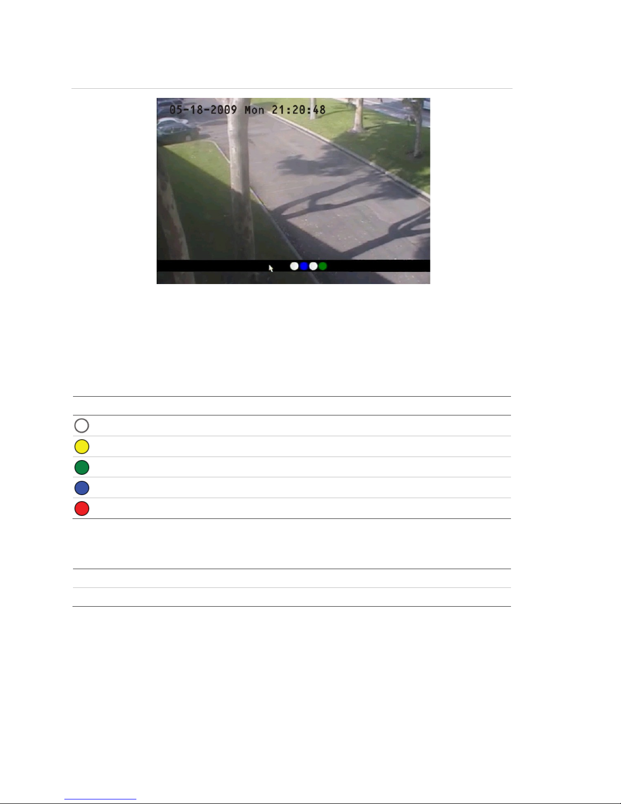
Chapter 4: Basic op er at ion
Icon
Mouse
Front panel/remote control
Figure 10: Recording status
Camera status
Each icon represents a camera. The icon color shows the camera status. Table 9
below gives the status color code..
Table 9: Camera status
Color Status description
White No video signal
Yellow Standby r ec or ding (when recording upon alarm and/or m otion)
Green Recording
Blue Motion detection
Red Alarm
Activating/deactivating the on-screen status bar
Right-click to open t he m ouse menu, and then click Status Bar.
Press # to activate or deactivate the status bar.
Cycling through camera vi ews
Right-click and then cli ck Camera or press the numeric buttons to switch to an
individual camera display. For example, you can press 2 to view the second
camera.
24 TruVision DVR 10 User Manual
Page 29

Chapter 4: Basic ope ration
Mouse
Front panel/remote control
Press DISP to manually toggle through single camera and four-screen views .
The single camer a display reverts back to camera 1 when switching to single
view. You can set the auto live mode on the Display menu.
Viewing in multiscreen
Right-click to open t he m ouse menu, and then click Multi
Screen. Select the desir ed display layout. You can select either
a four-screen or single screen view.
Press DISP to switch to m ultiscreen display viewing.
Connecting the spot monitor
To connect the spot monitor:
1. Connect Video out 2 with the spot monitor by a cable.
2. While in live mode, right-click and click Spot Channel.
3. You now have access to the secondary monitor.
Note: Make sure that there is video signal input; otherwise the spot monitor
will only show a blue screen.
Logging on
The TVR 10 is shipped with one predefined user for the system administrator.
The default system administrator log on uses “admin” as a user name with a
password of 1234. You can modify the admin password but not the admin user
name. We recommend that you change the admin password once you have
completed the installation and setup to protect against unauthorized access. The
administrator can create up to 15 users and define their privileges. For more
information, see “User settings” on page 39.
TruVision DVR 10 User Manual 25
Page 30
Chapter 4: Basic op er at ion
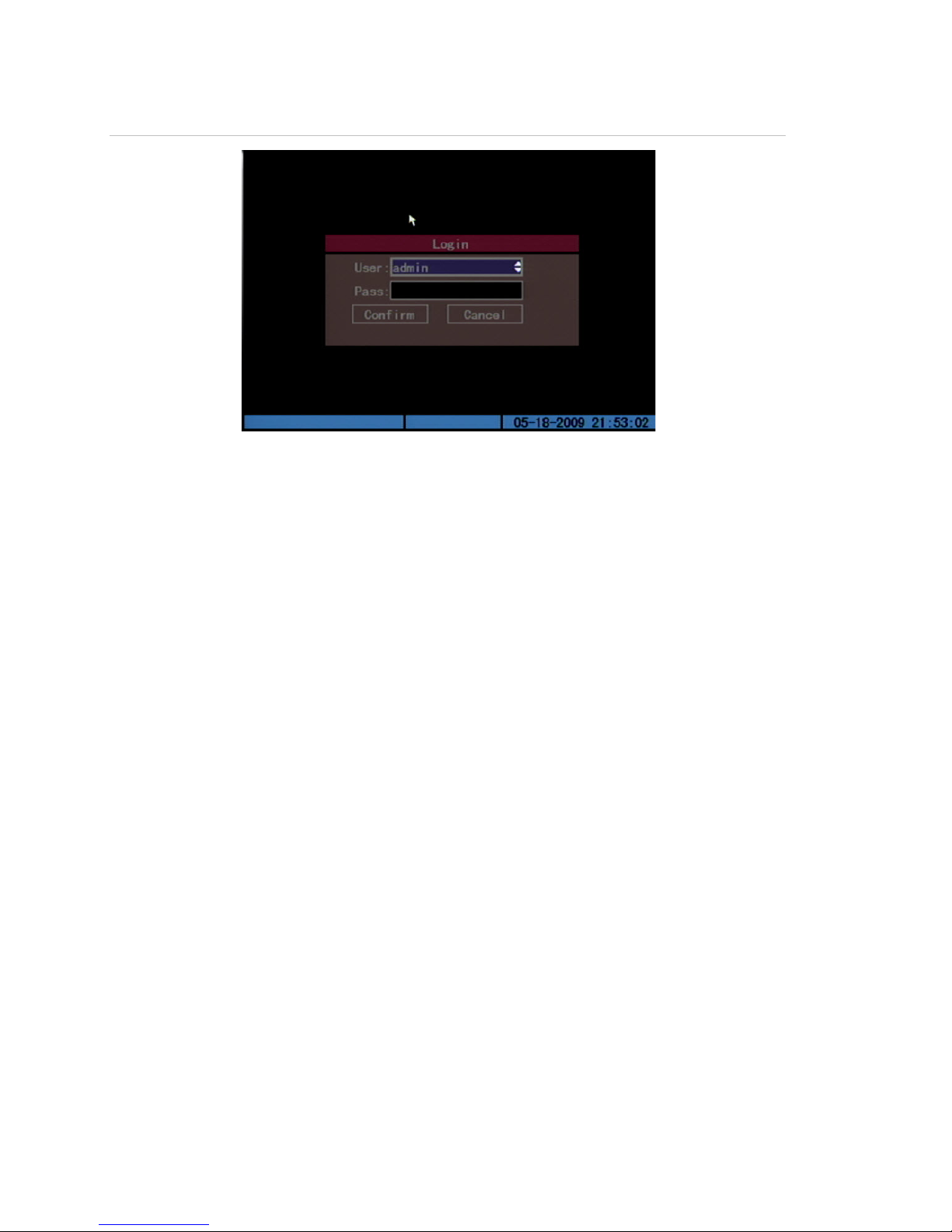
Figure 11: Login screen
To log on to the TVR 10 user interface:
1. In the User box, select a user.
2. Enter the corresponding password in the Password edit box.
3. Click Confirm to enter the main menu.
If there is no response, it means the user name and password are not
matched. The TVR 10 will enter the live mode if you enter unmatched logon
credentials three times.
Controlling a PTZ camera
The PTZ control interface lets you control the PTZ operation of the cameras
within the TVR 10 user interface. You can control PTZ cameras using the buttons
on the front panel and IR remote control as well as utilizing the PTZ contro l icons
accessed with the mouse. To display the PTZ control interface, the user must
have PTZ control access privileges.
Displaying the PTZ control interface
While in menu mode, right-click and then click PTZ control to display the PTZ
control interface directly. Select a user name and type the correct password in
the Login screen. The PTZ control interface displays as shown in Figure 12 on
page 27. You can adjust the position of the current camera display on the screen.
26 TruVision DVR 10 User Manual
Page 31

Chapter 4: Basic ope ration
Button
Up, Down, Left, Right Arrow
buttons
ZOOM+,
FOCUS+, FOCUS
IRIS+, IRIS
REC/SHOT
PLAY/AUTO
Figure 12: PTZ control interface
Selecting a camera
When in PTZ control mode, press the numeric buttons to select a camera. For
example, press the number 2 button to select the second camera PTZ.
After selecting the camera PTZ, you can use the control buttons to control the
PTZ.
PTZ control buttons description
Table 10 below provides descriptions of the PTZ control buttons.
Table 10: PTZ control buttons description
Description
Pans left and right. Tilt s up and down.
ZOOM- Zooms in and out.
- Focuses in and out.
- Opens and closes the iri s cont r ols.
Calls up a preset position. This feat ur e is camer a and protoc ol-
specific.
Calls up auto panni ng.
Calling up a preset PTZ position
There are several ways to call up a preset position.
TruVision DVR 10 User Manual 27
Page 32

Chapter 4: Basic op er at ion
Front panel
Remote control
Mouse
PTZ preset numbers are prepr ogr ammed.
Press PTZ to enter PTZ mode. Press REC and enter a preprogr am med
three-digit pr eset num ber . Preset starts immediately.
If you enter a one or two-digit number, depending on your TVR 10
model, you will change the selected camera.
This function is onl y available if the mouse is not connected to the TVR
10.
Press PTZ to enter PTZ mode. Press SHOT and enter a
preprogrammed three-digit preset number. Preset start s immediately.
If you enter a one or two-digit number , depending on your TVR 10
model, you will change the selected camera.
This function is onl y available if the mouse is not connected to the TVR
10.
Right-click and sel ec t PTZ cont r ol to enter PTZ mode. Right-click again
and select Preset. S elec t one of the preset numbers listed.
When you exit PTZ control mode, the camera stays at the current position.
Note: The PTZ preset position must already be configured. Refer to “PTZ
settings” on page 74 for more information. You can define up to 128 preset
positions.
Exiting PTZ control mo de
Press ESC or ENTER to exit and return to the live mode.
Manual recording
When a camera is recording, its corresponding LED on the front panel lights up
in green. This green LED is also lit when recording manually. Start or stop a
camera recording by pressing the REC button and entering the Manual Record
menu.
Note: You must have access privileges to enter the Manual Record dialog
screen.
Manual Record screen
To enter the Manual Record screen while in live mode, press REC and enter
your user name and password if requested.
28 TruVision DVR 10 User Manual
Page 33

Chapter 4: Basic ope ration
Option
Camera
Status
Start/Stop
Start All
Stop All
Figure 13: Manual Record screen
The controls and options available on the Manual Record screen are described in
Table 10 below.
Table 11: Manual Record controls and options
Description
Lists the number of cam er as the TVR 10 has.
Camera work status has four v alues:
• Gray indicates the cam er a is i dle.
• Green indicat es the c hannel is recording (including real time recording,
alarm recording, motion detection recording).
• Red indicates network transmission.
• Orange indicat es both r ec or ding and network transmission.
The chec kmark indicates you can start recording on the corresponding
channel . The X mark means you can stop recording.
Starts recording on all channel s.
Stops recording on all channels.
Manually starting or stoppi ng a recording
This section describes how to manual ly start or stop a recording.
To manually start or stop a recording:
1. Right-click and then click Manual Record to display the Manual Record
screen. Alternatively, press the REC button on the front panel or remote
control.
2. Enter your user name and password if requested.
TruVision DVR 10 User Manual 29
Page 34

Chapter 4: Basic op er at ion
The Manual Record screen displays listing all cameras. The camera status
line shows which cameras are currently recording.
3. Click the camera’s Start/Stop line to begin the recording. A checkmark
appears on that camera’s Start/Stop box.
4. Select the next camera you want to start or stop recording. Repeat step 3.
5. To select all cameras for recording, click Start All.
All camera status LEDs on the front panel and the on-screen camera status
icons on the status bar turns green.
6. Click Stop All to stop recording for all cameras.
7. Right-click or press ESC to save changes and return to the live mode.
Playing back video
The TVR 10 lets you play back recorded video. This section describes the
features and methods in playing back video.
Play Back screen
The Play back screen lets you search and view recorded video. You must be in
live mode to view video. Search for recorded video using different criteria
including:
• Motion detection, alarm, or manually recorded files
• Start and end time of recording
Note: You must have access privileges to enter the Play Back screen.
See Table 12 on page 31 for a description of the Play Back screen controls and
options.
30 TruVision DVR 10 User Manual
Page 35

Chapter 4: Basic ope ration
Option
Cam
Search for
Time
Search
Play
Page No.
File list box
Media
Archive
Archive Today
Figure 14: Play Back screen
Table 12: Play Back controls and options
Description
Selects a specifi c camer a.
Specifies a recorded fil e type. The file type options include: All, All Time,
Motion Detect, Alarm, and Manual.
Specifies a start and end date/t im e to conduct a search based on a
recording period.
Begins your search. If t her e ar e no files that match your search criteri a, a
corresponding screen displays.
Plays back the recorded stream directly based on the time section.
Selects a page. In the file list box, each page can only display eight files. If
more than eight files mat c h, you c an sel ec t a page t o list other files. 500
pages (4,000 fil es) can be searched at one time. You can use numeric
buttons or the Up or Down Arrow buttons to selec t page.
Lists the matched files. File start ed time and size are displayed in the list
box. You can use the Up or Down Arrow buttons to mov e the scroll bar to
select a file.
Selects a device (m edia) to back up y our recorded files. You can select USB
flash, USB HDD, or USB CD/DVD drive to back up the files or clips.
Starts backup.
Backs up all recorded files from today.
Searching for a recorded video
Prior to playing back a recorded video, you must first search for the video files
you want to play.
TruVision DVR 10 User Manual 31
Page 36

Chapter 4: Basic op er at ion
To search for recorded video:
1. Right-click and click Search in live mode or press PLAY on the front panel or
the remote control.
2. If requested, enter your user name and password. The Play Back screen
displays.
3. Select the camera you want to search video from in the Camera list box.
4. Select the file type of recorded video you want in the Search For list box.
5. For recording periods, enter the start and end dates as well as times in the
Time edit boxes.
6. Click Search to begin the search.
A list of files displays once the search is completed. The list may extend to
several pages. The files are listed by date, with the most recent file listed first.
7. Right-click or press ESC to quit playback and return to live mode.
Searching for motion detection video
When searching for motion detection video, if you select Always on the Rec Type
box in the Recording Schedule screen, you will not receive any motion detection
results. To search for motion detection video, select Motion, Motion or Alarm, or
Motion and Alarm on the Rec Type box in the Recording Schedule screen. For
more information, see “Defining a recording schedule” on page 63.
Playing back a recorded file
Once you have found the video files using the Play Back screen, you can view
video in several different ways:
• Click the Play button. The system starts playing each listed file.
— or —
• Click a video file in the File List box or select the file and press the ENTER
button. Only the selected file is played.
While playing back a video, an information bar displays the following information
as shown in Figure 15 on page 34:
• Volume
• Play progress
• Play speed
• Played time
• File total time
32 TruVision DVR 10 User Manual
Page 37

Chapter 4: Basic ope ration
Option
MENU
PLAY
Right or Left Arrow button
Up or Down Arrow butto
ENTER
PTZ Press once to copy the segment and again to stop. You will need an
ESC
SRCH
REC
ESC
MENU
REC
PTZ
Table 13: Playback interface options
Description
Di spl ay s or hides the information bar.
Turns the sound on or off.
Adjusts the play pr ogr ess by percent age ( %) .
n Adjusts the play speed: Normal speed is “1x.” Use the Up Arrow
button to increase pl ay speed (2X, 4X). Use the Down A r r ow butt on
to decrease play speed (1/2X, 1/ 4X, 1/8X and single)
Paus es or continues playback. If playing video in frame by frame,
use this option to play one fram e.
external back up dev ic e to store the segment in.
Exits the interface.
Mutes audio.
Zooms video.
Note: Performance of playback speed may decrease depending on how much
information the TVR 10 is processing.
Exiting play ba ck
There are several ways to exit the playback interface depending on the screen or
operating mode you want to access afterwards.
Takes you to live mode
Takes you to the main menu
Tak es you t o the Manual Record screen
Takes you to PTZ control mode
Playing back video with a mouse
Playing back video with a mouse provides you with an additional playback control
bar as shown in Figure 15 on page 34.
TruVision DVR 10 User Manual 33
Page 38

Chapter 4: Basic op er at ion
Control
ay speed
Figure 15: Playback control interface
Table 14: Playback control bar description
Name Description
Skip reverse/forward Skips backward or forward 3% each time.
Fast forward/ Slow
forward
Adjusts the play speed: Normal speed is “1x.”
Use the Up Arrow button to increase pl
(2X, 4X). Use the Down Arrow button to
decrease play speed (1/2X, 1/4X, 1/8X and
single)
Pause Pauses the video.
Audio Toggles between mute and sound. Click once
to mute the video. Click again to recover the
sound.
Copy Copies a video segment . Click once to start the
copy. Click agai n to stop.
Hide Status Hides the control bar. Right-click your mouse
and click display to display the control bar
again.
Search Triggers a rect angle ar ea on the screen to
zoom into. Use the left mouse butt on to drag a
rectangle around the area, and then doubleclick to zoom into that area. Click again to
return to the playback interface.
Toggle camera Switches to the next or pr ev ious pl ay bac k
34 TruVision DVR 10 User Manual
cameras. These options are irrelevant if you
only recorded usi ng one c am er a at t hat time.
Page 39

Chapter 4: Basic ope ration
Archi ving recorded files
Archive recorded files using an external device. You can also archive specific
incidents in a file. You must be in live mode to play back a recorded file.
You can insert a mini-USB hub to the USB port to attach a mouse for navigation
and a USB drive for archiving. However, the unit may not support all types of
USB hubs.
Note: You must have playback privileges to play back recorded files. Avoid
moving the external recording device when backing up information onto it.
Archiving the day’s recorded files
Use the Archive Today option on the Play Back screen to archive all the day’s
recordings. A dialog box displays the backup status.
If the external device is not connected correctly or the TVR 10 does not detect
the external device, an alert dialog displays. Please alert the administrator if this
occurs.
Archiving recorded files from a file list
You can also archive recorded files displayed in the File List box.
To archive files from the File List box:
1. Search for recorded files.
For more information on searching for recorded files, see “Search ing for a
recorded video” on page 31.
2. Select the files that you want to back up.
In the file list box, click the file you want to archive. The checkmark symbol
indicates a selected file. Select additional files you want to archive. You can
use the Up and Down Arrow buttons to move through the files as shown in
the figure below. Press ENTER to select the file you want to archive.
TruVision DVR 10 User Manual 35
Page 40

Chapter 4: Basic op er at ion
3. Use the Media box to select the backup device you want to use.
4. Click Archive to start the archiving process.
When the archiving starts, a corresponding message box displays, indicating
the status. If the selected files exceed the capacity of your storage device, an
error message displays.
Archiving a video segment
While playing back a recorded file, the TVR 10 lets you archive a specific
segment of the video you are watching.
To back up image segments during playback:
1. Enter the playback interface by selecting a recorded file. For more
information, see “Playing back a recorded file” on page 32.
2. While the video is playing, press PTZ to begin recording the video, and press
PTZ again to stop recording. A video segment is created.
3. You can repeat step 2 to create additional segments. You can generate up to
30 additional segments.
4. After all segments have been created, press ESC. A confirmation message
window displays. Press Confirm to begin archiving the selected segments.
Press Cancel to abort the archive process.
Playing back the archived files
Use the standard file player softwar e to play back the video segment on your PC.
36 TruVision DVR 10 User Manual
Page 41

Chapter 4: Basic ope ration
Turning off the TVR 10
To turn off the TVR 10:
1. On the main menu, click Utilities, and then click Power Off.
— or —
Press and hold the Power button on the remote control for at least five
seconds. Enter a user name and password if required.
2. Wait 10 seconds then turn off the power switch located on the back of the
unit.
TruVision DVR 10 User Manual 37
Page 42

Page 43

Chapter 5
Advanced s etup
This chapter covers the advanced setup of your TVR 10. Only users with
appropriate access privileges can define and modify advanced configurations.
When the following settings are modified and saved, you will be prompted to
reboot the TVR 10 in order for the new settings to take effect. You do not need to
reboot the device for any other configurations.
• Any network configurations
• Resolution and record schedule
• External alarm sensor type
• View tampering alarm schedule
• Video loss alarm schedule
• Motion detection alarm schedule
• External alarm schedule
• Alarm output schedule
User settings
The TVR 10 is shipped with one predefined user for the system administrator.
The default system administrator log on uses admin as a user name with a
default password of 1234. You can modify the admin password but not the admin
user name.
The administrator can create up 15 users and define their privileges. When new
users are added to the list, the administrator can define individual passwords or
each user can use a default password.
TruVision DVR 10 User Manual 39
Page 44

Chapter 5: Advanced setup
Modifying your password
Passwords limit access to the TVR 10 and the same password can be used by
several users. When creating a new user, the default password is 0000. Each
standard user can modify his or her own password. However, only an
administrator can assign or unassign a password to a user. Specify an admin
password of up to four digits, ranging from 1 to 4, to allow you access to the
system from the front panel and without using the remote control or mouse.
Note: Keep the admin password in a safe place. If you should forget the
password, you must return the unit to a service center to be reconfigured.
To modify your password using the mouse or remote control:
1. Log on to the main menu.
2. Click User to display the User screen.
3. Select the target user name.
Click on a user or use the Up or Down Arrow buttons to select a user as
shown in the figure below. Click the Password edit box to enter into edit
mode.
4. Enter the new password.
Use numeric buttons to enter the new password. Passwords can be up to 16
numeric characters. T he password edit box can be left b lank. This indicates
that the selected user does not have a password.
5. Verify the new password.
Click the Verify edit box, and enter the new password again to verify the
change. In the edit box, use the Left or Right Arrow button to move the cursor
and press DEL to delete the numer al in front of the cursor.
6. Click Confirm to accept the change and return to the main menu.
40 TruVision DVR 10 User Manual
Page 45

Chapter 5: Advanced setup
If the initial and verify passwords entered are identical, the password is saved
and becomes effective immediately. However, if both passwords do not
match, a warning message appears as shown in the figure below. Press
ENTER to confirm and you are returned to the password edit box to the new
password again.
Adding a new user
Only the system administrator can add or delete users. Up to 15 users can be
created.
To add a new user:
1. Click User on the main menu to display the User screen.
2. Click Add to display the Add screen as shown in the figure below.
3. Enter a new user name using alphanumeric character s.
TruVision DVR 10 User Manual 41
Page 46

Chapter 5: Advanced setup
4. Click Confirm (or press ENTER) to confirm. The User screen displays with the
new user name listed.
After adding a new user, the password field remains blank. You can leave the
password field blank, or you can assign the user a password. For more
information, see “Modifying your password” on page 40.
Assigning access privileges
All new users must be granted user privileges as privileges are not automati cally
defined by the system. Users can be given local privileges to do playback,
remote playback, and view logs. You can also grant them more extensive
privileges that cover both local and remote privileges. For more information, see
“Access privileges” on page 43.
To assign access privileges to a user:
1. Click User on the main menu to display the User screen.
2. In the User Box, select a user to whom you want to assign access privileges.
3. Click Default Privileges to assign default privileges to the user. Default
privileges include local playback, remote playback, and viewing logs.
4. Click Set Privileges to allocate more detailed access privileges. The Set
Privileges screen displays as shown in the figure below.
5. Assign local and/or remote access privileges to the user.
Check each item to select it. This enables or disables that item. Users can be
given both local and remote access privileges. For more information, see
“Access privileges” on page 43.
6. Click Confirm to save the changes and return to the main menu.
42 TruVision DVR 10 User Manual
Page 47

Chapter 5: Adv anced setup
Option
PTZ control
Record
Set parameters Set up
Log
Utilities
Option
PTZ C
Record
Set parameters Set up
Log
Utilities
Talk
Alarm
Local Video Out
Com Control
Access privileges
Access privileges define what areas in the system a user can access. The TVR
10 access privileges are categorized into two different areas: local and remote.
Local
Local privileges are for local operation, such as the operating the unit using the
front panel, IR remote control, and RS-485 interface.
Table 15: Local privileges
Description
Locally contr ols PTZ
Manual starts or stops recording
Locally sets up the TVR 10 parameters
Locally vi ews the log on TVR 10
Locally upgrades fi rmware, formats the HDD, reboots the
TVR 10, and shuts down the TVR 10, etc.
Remote
Remote privileges allow users to use the TVR 10 through a network.
Table 16: User privileges for remote operation
Description
ontrol Remote control PTZ
Remote manual start/ stop r ec or ding
Remote setup the T VR 10 parameters
Remote view the log on T V R 10
Remote upgrade fi rmware, format HDD, reboot TV R 10, and
shut down TVR 10, etc .
Client talks with TVR 10
Remote control TVR 10 alarm output
Remote control TVR 10 video output
TVR 10 RS-232
TruVision DVR 10 User Manual 43
Page 48

Chapter 5: Advanced setup
Setting up the MAC address
Setting up a user with a MAC address from the user’s computer prohibits access
to the TVR 10 from other computers.
To set up a MAC address:
1. At the PC DOS prompt, use the “ipconfig” command to obtain the MAC
address of that PC (in 6 bytes).
2. On the TVR 10 User screen, cli ck Set Privileges to display the Set Privileges
screen.
3. Click the MAC address edit box. Use the virtual keyboard with the mouse or
the number buttons on the IR remote control to enter the MAC address. Press
ENTER to accept the entry.
4. Click Confirm to retur n to the User screen.
5. Click Confirm again to return to the main menu.
Deleting users
Only the system administrator can add or delete users.
To delete a user:
1. On the User screen, select the user you want to delete.
2. Click Del to delete that user. A confirmation dialog displays as shown below.
3. Click Confirm to delete the user and return to the User screen.
4. On the User screen, click Confirm to save the changes and return to the main
menu.
44 TruVision DVR 10 User Manual
Page 49

Chapter 5: Adv anced setup
Camera settings
This section describes how to change camera settings from the Camera
Configuration screen. Camera options that you can configure are listed below.
You can change these settings in any order. The options are:
• Name of each camera
• Camera name position on screen
• Camera brightness, contrast, saturation, and hue
• Display properties of each camera
• Area on screen to be masked
• When to view a tamper al arm
• Video loss alarm
• Motion detection alarm
All changes made on the Camera Configuration screen apply only to the selected
camera. You can easily copy the camera settings of one camera to another.
Figure 16: Camera configuration screen
Camera name
Each camera can be assigned a camera name which must be unique. If you do
not assign a camera name, a default prenumbered camera name is applied.
To change a camera name:
1. Click Camera on the main menu to display the Camera Configuration screen.
TruVision DVR 10 User Manual 45
Page 50

Chapter 5: Advanced setup
2. Select a camer a from the Camera box.
3. Enter the new camera name in the Camera Name edit box.
Click the Camer a Name edit box to enter the edit mode. You can enter
numerals, uppercase and lowercase letters (see “Using an edit box” on page
21 for more information). The camera name can support 32 characters. Press
ENTER to exit the edit mode.
4. Click Confirm to save your changes. Click Cancel or press ESC to abort.
Camera name position
You can position the camera name anywhere on screen. If you do not want to
display the camera name, clear the check box next to the Camera Name edit
box. You can copy the position settings to any other camera.
To edit a camera’s position:
1. Click Camera on the main menu to display the Camera Configuration screen.
2. Select a camera from the Camera box.
3. Enter the Camera Name Position Setup interface.
Check the check box on the right side of the camera name, then click Position
to enter the Camera Name Position Setup screen.
4. Position the camera name.
The interface displays a grid with the camera name in the bottom right corner.
Drag the camera name or use the directional arrow buttons (Up, Down, Left,
or Right) to move the camera name position. When satisfied with the onscreen position, press ENTER to return the Camera Configuration screen.
5. Click Confirm to save the camera position.
On-screen date and time position
In addition to the camera name, the TVR 10 also displays the system date and
time on screen. You can modify the on-screen display position (also referred to
as OSD) of the system date and time on the Camera Configuration screen.
To position the camera name on screen:
1. Display the Camera Configuration screen and select a camera.
2. Select a display mode for the camera from the Date & Time OSD list box.
Display modes include:
• Solid black
46 TruVision DVR 10 User Manual
Page 51

Chapter 5: Adv anced setup
• Solid white
• Not displayed
3. Enter the Date and Time Position Setup interface.
Click the Date & Time OSD Position button to enter the Date and Time
Position Setup interface as shown in the figure below.
4. Position the on-screen date and time.
The interface displays a grid with the date and time at the top center of the
screen. Drag the date and time grid or use the directional arrow buttons (Up,
Down, left, or Right) to move the date and time position. When you are
satisfied with the on-screen position, press ENTER to return the Camera
Configuration screen.
5. Click Confirm to save the camera position.
Adjusting the video image
In order to get the best image quality when capturing video, you may need to
adjust the video image settings including brightness, saturation, contrast, and
hue. Use the Adjust screen (as shown in Figure 17 on page 48) on the Camera
Configuration screen to modify these settings.
You can set up the video adjustments individually, and copy the video
adjustments of one camera to another.
TruVision DVR 10 User Manual 47
Page 52

Chapter 5: Advanced setup
Figure 17: Adjust video screen
To adjust the video image:
1. Display the Camera Configuration screen and select a camera.
2. Click the Adjust Video Setup button to display the Adjust Video screen.
3. Make the appropriate video image adjustments.
You can adjust the video image’s brightness, contrast, hue, and saturation by
clicking the corresponding Adjust button. Click the corresponding Adjust
button to display the Adjust screen. The screen displays the camera view with
a scroll bar at the bottom of the screen. Use the scroll mouse button or the Up
or Down Arrow buttons in the interface to make your adjustments. As you
make your adjustments, the camera view displays the corresponding
adjustment.
4. When satisfied, click anywhere in the screen to r eturn to the Adjust Video
screen.
5. Click Confirm to save your changes.
Privacy masking
The TVR 10 lets you define an area on screen that can remain hidden from vi ew.
For example, you can choose to block the view of a camera when overlooking
residential premises. This hidden ar ea is referred to as privacy masking. Privacy
masking cannot be viewed live or recorded, and appears as a blank screen on
display.
Figure 18 on page 49 provides an example of the privacy masking function.
48 TruVision DVR 10 User Manual
Page 53

Chapter 5: Adv anced setup
Figure 18: Area masked
To define privacy masking:
1. Display the Camera Configuration screen and select a camera.
2. Click Advanced Settings Setup to display the Advanced Settings screen.
3. Select the Enable the Privacy Masking check box to enable privacy masking.
4. Click Privacy Masking Zone to enter the Mask Area Setup interface.
The setup interface displays a grid (22 x 18 panes for PAL, 22 x 15 for
NTSC). A single pane in yellow is displayed at the top left corner. The yellow
pane indicates the area to be masked.
5. Select the areas to be masked.
Move the pointer and click or use the directional arrow buttons (Up, Down,
Left, or Right) to move the yellow pane to the zone you want to mask. Click
the mouse again to select that area for privacy masking. The yellow panes
turn red, indicating that this area will be hidden from view. Drag the mouse or
use the directional arrow buttons to extend or shrink privacy masking as
shown in the figure below.
TruVision DVR 10 User Manual 49
Page 54

Chapter 5: Advanced setup
6. Click the mouse to save that area for privacy masking.
7. Press ENTER to return to the Advanced Settings screen.
8. Repeat steps 4 to 7 for additional areas for privacy masking. You can set up
four masked areas on a screen.
9. Click Confirm on the Advanced Settings screen to save your changes and
return to the main menu.
Note: The cancel privacy masking, disable the Privacy Masking option on the
Advanced Settings scr een.
Camera tamper alarm
The TVR 10 lets you define camera tamper alarms. A camera tamper alarm
refers to an alarm triggered when a camera view is blocked (either deliberately or
accidentally). For example, the system can trigger an alarm if someone spray
paints the camera lens. The alarm displays on the status bar of the scr een.
Use the Rules screen (shown in Figure 19 on page 51) to specify a part of the
display screen that can detect a tamper that eventually triggers the alarm. In
addition, you can define how the system alerts you of the tamper alarm.
50 TruVision DVR 10 User Manual
Page 55

Chapter 5: Adv anced setup
Figure 19: View Tampering Handle screen
Defining a camera tamper alarm requires the following tasks:
1. Specify the detection sens itivity le v el.
2. Define the on-screen area that can trigger a camera tamper alarm.
3. Configure the tamper alarm response.
Note: These tasks define a camer a tamper alarm for only a single camera. You
will need to perform these tasks for every camera that requires a tamper alarm.
To specify the detection sensitivity level:
1. Display the Camera Configuration screen and select a camera.
2. Click Advanced Settings to display the Advanced Settings screen.
3. Set the detection sensitivity level.
Select a camera tampering option in the Camera Tampering list box. Values
include: Off, Normal, High. If Normal or High is selected, the Area and Rules
buttons become available.
To define the on screen area that can trigger a camera tamper alarm:
1. In the Advanced Settings screen, click Camera Tampering Area to display the
Camera Tampering Area screen.
2. Define the area for camera tampering.
Defining an area for camera tampering is similar to masking an area for
privacy. See steps 4 to 7 on page 49 for further instructions.
3. When finished, right-click and then click OK to confirm your changes.
Note: Only one tam pering area can be defined for each camera.
TruVision DVR 10 User Manual 51
Page 56

Chapter 5: Advanced setup
To define the tamper alarm response:
1. In the Advanced Settings screen, click Camera Tamper Area to display the
Camera Tamper Rules screen.
2. Define an alarm schedule.
The system’s handling of a camera tamper alarm depends on the alarm
schedule. In the Rules screen, select the day of the week in the Alarm
Schedule list box for which you want to set the response time schedule. Enter
the time period for the r esponse in the Period edit boxes. You can enter up to
four time periods for each day of the week.
3. Select a response method.
Check a response method for the system when a camer a tamper alarm is
triggered. You can check one or more response methods including:
Full Screen. Displays the alarm on the screen.
Buzzer. An audible alarm sounds.
Upload to Client. This feature is currently not supported.
Alarm Out. Triggers an alarm output. Up to four alarm outputs can be
enabled.
Check or use the Up or Down Arrow buttons and the ENTER button to enable
or disable these options.
4. Click Confirm on the Rules screen to save your setup.
Note: The TVR 10 will prompt you to reboot in order for the schedule to take
effect.
Video loss alarm
The TVR 10 lets you define video loss alarms. A video loss alarm refers to an
alarm triggered when a video signal is lost or corrupt due to power failure, video
cable failure, bad connection, and more. The video loss alarm triggers only if the
video loss occurs during a programmed time schedule. The Video Loss screen
lets you define video loss alarms as shown in Figure 20 on page 53. The alarm
displays on the status bar of the screen.
52 TruVision DVR 10 User Manual
Page 57

Chapter 5: Adv anced setup
Figure 20: Video signal loss handle screen
To define a video loss alarm:
1. Display the Camera Configuration screen and select a camera.
2. Click Advanced Settings to display the Advanced Settings screen.
3. Click Video Loss option. The Rules option becomes active.
4. Define the video loss alarm schedule.
The system’s handling of a video loss alarm depends on the alarm schedule.
In the Rules screen, select the day of the week in the Alarm Schedule list box
for which you want to set the response time schedule. Enter the time period
for the response in the Period edit boxes. You can enter up to four time
periods for each day of the week.
5. Select a response method.
Check a response method for the system when a camer a tamper alarm is
triggered. You can check one or more response methods, including:
Full Screen. Displays the alarm on the screen.
Buzzer. An audible alarm sounds.
Upload to Client. This feature is currently not supported.
Alarm Out. Triggers an alarm output. Up to four alarm outputs can be
enabled.
Check the check box or use the Up or Down Arrow buttons and the ENTER
button to enable or disable these options.
6. Click Confirm on the Rules screen to save your setup.
Note: The TVR 10 will prompt you to reboot in order for the schedule to take
effect.
TruVision DVR 10 User Manual 53
Page 58

Chapter 5: Advanced setup
Button
Up, Down, Left, Right Arrow
buttons
Right Arrow button
Left Arrow button
Down Arrow button
Up Arrow button
PTZ
#
ENT
ESC
7. Repeat steps 2 to 6 for additional cameras.
Motion detection alarm
The TVR 10 lets you define motion detection alarms. A motion detection alarm
refers to an alarm triggered when a camera detects a motion. The alarm displays
on the status bar of the screen.
You can define the level of sensitivity to motion, the area on screen where the
motion is detected, and specify which cameras can record the motion when a
motion alarm is detected.
If you enable this function, the TVR 10 will display the alarm on the status bar on
the screen when motion is detected.
Use the following PTZ buttons to define motion detection areas.
Description
Moves the yellow pane to any posit ion
Increases the motion detection area si z e from the ri ght
Decreases the motion detection area size from the left
Increases the motion detection area size downwards
Decreases the moti on detection area size upwards
Selects the whole screen as a m otion detection area
Clears all motion detection areas
ER Saves changes and returns to the Camera Configurati on screen
Cancels the setup and returns to the Camera Configuration
screen
To define motion detection areas:
1. Display the Camera Configuration screen and select a camera.
2. Set the motion detection sensitivity level.
Select a level from 0 (lowest sensitivity) to 6 (highest sensitivity), as well as
the Off option in the Motion Detection list box. Selecting an option other than
Off activates the Motion Area and Motion Rules options.
3. Display the Motion Detection Area setup interface.
The setup interface displays a grid (22 x 18 panes for PAL, 22 x 15 for
NTSC). A single pane in yellow is displayed in the top left corner. T he yellow
pane indicates the area for motion detection.
54 TruVision DVR 10 User Manual
Page 59

Chapter 5: Adv anced setup
4. Define the motion detection area.
Move the pointer or use the directional arrow buttons (Up, Down, Left, or
Right) to move the yellow pane to the zone you want to mask. Click to select
that area for motion detection. The yellow panes turn red, indicating an alarm
will trigger if motion is detected within this area. Drag the mouse or use the
directional arrow buttons to extend or shrink the motion detection area.
5. Click in the red area to save that ar ea for motion detection and return to the
yellow pane to continue defining areas as shown in the figure below.
6. Repeat steps 4 to 6 for additional motion detection areas. You can set up four
masked areas on a screen.
7. To clear part of a motion detection area, move the yellow pane to the motion
detection area you want to delete and press REC. To clear all motion
detection zones, press #.
8. Click the mouse to return to the Camera Configuration screen.
To define the motion alarm response rules:
1. Display the Motion Detection Alarm Rules screen.
Click Motion Detection Rules to display the Motion Rules dialog screen as
shown in the figure below.
TruVision DVR 10 User Manual 55
Page 60

Chapter 5: Advanced setup
2. Select the cameras you want to record for motion detection.
Select the cameras you want to begin recording when the system receives a
motion detection alarm. Check one of the camera boxes to select that
camera. Click again to deselect. You can select more than one camera.
Note: For cameras to be able to record for a moti on detection alarm, you
must first configure them for motion recording. See “Defining a recording
schedule” on page 63 for more information.
3. Define an alarm schedule.
The system’s handling of a motion detection alarm depends on the alarm
schedule. On the Motion Detection Alarm Rules screen, select the day of the
week in the Alarm Schedule list box for which you want to set the response
time schedule. Enter the time period for the response in the Period 1 edit
boxes. You can enter up to four time periods for each day of the week. The
four daily time periods cannot overlap.
Use the Copy option to copy the same periods to a different weekday.
Note: You will be prompted to reboot the TVR 10 in order for the schedule to
take effect.
4. Select a response method.
Check a response method for the system when a motion detection alarm is
triggered. You can check one or more response methods including:
Full Screen. Displays the alarm on the screen.
Buzzer. An audible alarm sounds.
Upload to Client. This feature is currently not supported.
Alarm Out. Triggers an alarm output. Up to four alarm outputs can be
enabled.
56 TruVision DVR 10 User Manual
Page 61

Chapter 5: Adv anced setup
Check the check box or use the Up or Down Arrow buttons and the ENTER
button to enable or disable these options.
5. To copy the alarm rules to another day, select a day in the Copy to list box
and click Copy.
6. Click Confirm on the Rules screen to save your setup.
Note: The TVR 10 will prompt you to reboot in order for the schedule to take
effect.
Display settings
Use the Display screen to configure how information is displayed on screen. The
following options can be configured:
• Device ID
• Password requirement option
• Video output standard
• Video scaling
• Menu transparency
• System time and date
• Multiscreen
Device ID
The device ID provides a means for an IR remote control to connect to the TVR
10. If there is mor e than one TVR 10 in a setting, you must define a different
device ID for each TVR 10. Otherwise, the IR remote control will control all TVR
10s with the same device ID at the same time. The default device ID is 01.
TruVision DVR 10 User Manual 57
Page 62

Chapter 5: Advanced setup
To change the device ID:
1. Click Display on the main menu to open the Display screen as shown in the
figure below.
2. Click the Device ID edit box to enter into edit mode.
3. Enter the new device ID. The device ID value ranges from 1 to 255.
4. Click Confirm to save your changes.
Video output standard
The TVR 10 can support NTSC or PAL video output. NTSC is the default format.
To modify the video output standard:
1. Click Display on the main menu to open the Display screen.
2. Select a either PAL or NTSC video output in the Video Standard list box.
3. Click Confirm to save your changes.
System date and time
Configure the TVR 10 system date and time in the Date & Time screen as shown
in Figure 21 on page 59. You can also enable Daylight Saving Time (DST) and
date format in this screen. The date and time configured on this screen appears
on the video display.
58 TruVision DVR 10 User Manual
Page 63

Chapter 5: Adv anced setup
Figure 21: Date & time screen
To configure the TVR 10 system date and time:
1. Select Display in the main menu to display the Display Configuration screen.
2. Click Date & Time Setup to display the Date & Time screen.
3. Specify a date format using the Date Display Mode list box.
The following are available formats:
• MM DD YY
• DD MM YY
• YY MM DD
4. Enter a date.
Click the Date edit box to enter into edit mode. Use the number buttons to
enter a date.
5. Enter the time.
Click the Time edit box to enter into edit mode. Use the number buttons to
enter the time.
6. Check Daylight Saving Time (if applicable).
Check the Enable DST check box to enable Daylight Saving Time. Select the
month, date and time when Daylight Savings starts and stops using the From
and To list boxes.
7. Click Confirm to save your changes.
TruVision DVR 10 User Manual 59
Page 64

Chapter 5: Advanced setup
Button
DISP
Numeric buttons (1
Multi-screen l ayout
When you turn on the TVR 10, the system automatically enters into the live
mode. Use the following buttons to toggle between different display options:
Function
Toggles between a single screen display to a four screen display
-4) Swit c h between cameras on a single screen
The Multi-Screen screen, displayed in Figure 22 below, lets you configure the
display properties when in live mode. T o display the Multi-Screen screen, click
Display on the main menu, and then cli ck Multi-Screen. Click Confirm to save
your changes and return to the Display Configuration screen.
Figure 22: Multi-screen screen
Display mode
The Display Mode list box lets you specify how many screens appear during live
mode. Use the Up or Down Arrow buttons to select between options. You can
select a single screen or four screens.
Dwell time
The Dwell time list box lets you specify amount of time a screen is displayed
before moving into a different screen. Use the Up or Down Arrow buttons to
select one of the following options:
• 5 seconds
• 10 seconds
• 20 seconds
• 30 seconds
60 TruVision DVR 10 User Manual
Page 65

Chapter 5: Adv anced setup
• 1 minute
• 2 minutes
• 5 minutes
• Never
Audio preview
Check the Audio Preview check box if you want the TVR 10 to play the audio of
the camera when displaying a single camera.
Display layout setup
Use this option to define the order of the cameras to be displayed when in live
mode. If you have selected a four-screen display mode, the video frame should
display four panels. Select a panel and press a numeric button corresponding to
the camera number you want to display in that panel. Continue for each camera.
The preview order is displayed on a status bar below the preview frame as
shown in Figure 22 on page 60.
Saving the display setup
Click Confirm to save your setup.
Recording settings
Use the Recording Configuration screen, shown in Figure 23 on page 62, to
define how the TVR 10 records video. The following options can be configured:
• Handling of information when the HDD is full
• Audio and/or video recorded
• Bit rate
• Frame rate
• Camera resolution
• Recording schedule of a camera
• Pre and post recording times for alarm recordings
TruVision DVR 10 User Manual 61
Page 66

Chapter 5: Advanced setup
Option
Stream Type
Resolution
Bit rate
Figure 23: Recording channel configuration
Record mode
This option lets you specify how the TVR 10 responds when the HDD becomes
full. Select Stop Recording to trigger a Hard Disk Full exception. Recording will
not continue if the HDD is full and you have the Stop recording option selected.
Select Overwrite to overwrite the earliest recorded files when the HDD is full to
continue recording.
Camera recording
This option lets you specify the camera for which you want to define the
recording configuration. Use the Up or Down Arrow buttons to select a camera.
Table 17 below lists the recording options you can configure for your camera.
Table 17: Camera recording options
Description
Specifies the stream type you wish to record. Sel ect Video to r ec or d v ideo
stream only. Sel ect A udio& Vi deo to record both video and audio streams.
Specifies the recor ding r esol ution. A higher image resolution pr ov ides a
higher image quality but also requires a higher bit rate. The cam er a
resolution ranges from QCIF (lowest) up to 4CIF (highest).
If you make changes to this option, you must reboot the TVR 10 to
implement the changes.
Specifies the maximum bit rate. Recommended bit rate depends on the
camera resolution.
62 TruVision DVR 10 User Manual
Page 67

Chapter 5: Adv anced setup
Option
Fra
Pre
event time to 5 seconds, the
Post
Record
Schedule
Description
me Rate Specifi es the frame rate for the selected resolution.
Options incl ude: 25 (P A L)/30 ( NTSC) 22, 20, 18, 16, 15 , 12, 10, 8, 6, 4, 2,
and 1.
-Event Time This option i s used if you have the motion detection and/or external alarms
enabled. Pre-event time refers to the time recorded before a motion or
external alarm is tri gger ed and includes the alarm data. If a motion or
external alarm occurs and you have set the preTVR 10 will record and save up to 5 seconds prior to the alarm ev ent. Preevent time options i ncl ude: No Prerecord, 5 (default), 10, 15, 20, 25, 30
seconds, and Max Prerecor d. Max Prerecord lets you save all data in the
Prerecord buff er .
Pre-event time relates to the bit rat e in that the lower the bit rate, the longer
the actual pre-event time.
-Event Time This option is used if you have the motion detection and/or external alarms
enabled. When an external or motion alarm is cleared, the T VR 10 will
continue recor ding based on the value specified in this option. Opti ons
include: 5 (def ault), 10, 30 seconds, 1, 2, 5, and 10 minutes.
Enables or disables recording for the selec ted camera.
Def ines a recording schedule when you enable cam er a r ec or ding.
When you modify the camer a recording schedule, you must reboot TVR 10
to implement the changes.
Defining a recording schedule
When enabling a camera for recording, you can define a recording schedule for
the selected cameras. You will be prompted to reboot the TVR 10 after making
any schedule modifications. Use the Recording Schedule screen to define a
schedule as shown in Figure 24 on page 64.
TruVision DVR 10 User Manual 63
Page 68

Chapter 5: Advanced setup
Figure 24: Recording schedule screen
To define a recording schedule:
1. Display the Schedule screen.
On the Recording Channel Configuration screen, click Record to enable
recording. Then click Schedule to display the Schedule screen.
2. Select a day of the week for which you want to set the recording schedule.
Select a day of the week using the Day list box to define specific periods for
recording during that day. If you want to the TVR 10 to record the entire day,
check All Day to enable All Day recording.
3. Set the start and end time for recording.
Click the Start Time edit box and enter a time you want the TVR 10 to begin
recording. Click the End Time edit box option to specify an end time.
4. Select a recording type.
Select one of the recording types:
• Always
• Motion
• Alarm
• Motion or alarm
• Motion and alarm
• Command
If you checked the All Day recording check box, this box is automatically set
to Always. To be able to search for motion detection video, select Motion,
64 TruVision DVR 10 User Manual
Page 69

Chapter 5: Adv anced setup
Motion or Alarm, or Motion and Alarm in this box. For more information, see
“Searching for motion detection video” on page 32.
5. Repeat steps 3 to 4 for additional periods.
Note: The four daily time periods cannot overlap.
6. Set the schedule periods for the other days of the week as required.
Use the Copy To option to copy the scheduled periods to another day of the
week.
7. Save your changes
Click Confirm to return to the Recording screen. Click Confirm again to save
your changes and return to the main menu.
Notes
• The TVR 10 will prompt you to reboot in order for the schedule to take effect.
• If you set your record type to Motion or other related types, you must define
the Motion Detection alarm in order to trigger motion recording. See “Motion
detection alarm” on page 54 for more information.
• If record type is Alarm or other related types, you must define alarms to
trigger alarm recording. See “Alarm settings” below for more information.
Alarm settings
Use the Alarms screen to define how the TVR 10 handles alarms. You can select
how the alarm settings should be handled such as:
• An external alarm input
• An internal alarm i nput
• Notification settings
Click Alarms on the main menu to display the Alarms screen as shown in
Figure 25 on page 66.
TruVision DVR 10 User Manual 65
Page 70

Chapter 5: Advanced setup
Figure 25: Alarms screen
To set up an external alarm input:
1. Select an alarm input in the Alarm Input box.
2. Select an input type in the Input Type box.
Alarm input type refers to the sensor type. You can select Normal Open or
Normal Close according to the sensor type.
3. Enable the alarm input.
Select the Alarm check box to enable that alarm input. The Rules and PTZ
Rules options become active.
4. Select your cameras for alarm handling.
Click Rules to display the Alarm In Handling screen as shown below.
Check the cameras from which you want to record an alarm input in the
Record Camera check boxes to enable or disable the camera channel.
66 TruVision DVR 10 User Manual
Page 71

Chapter 5: Adv anced setup
Note: In order for a camera to record an alarm, the recording option and type
must be enabled on the Schedule screen. See “Defin ing a recording
schedule” on page 63 for more information.
5. Define your alarm handling schedule.
In the Alarm Schedule section of the Alarm In Handling screen, define a
schedule for when the TVR 10 will respond to an external alarm. Select the
day of the week and under Period 1 enter the start and end time periods for
the selected day.
6. Specify your response method.
Select how you want to be notified of an external alarm. Check one or more of
the following response methods:
Full Screen. Displays the alarm on the screen.
Buzzer. An audible alarm sounds.
Upload to Client. This feature is currently not supported.
Alarm Out. Triggers an alarm output. Up to four alarm outputs can be
enabled.
7. Click Confirm to save your settings and return to the Alarms screen.
Note: The TVR 10 prompts you to reboot in order for the schedule to take
effect.
8. Set a PTZ link to the alarm.
In the Alarms screen, click PTZ Rules to display the PTZ Rules screen, as
shown in the figure be low .
Select a camera, and then click one or more of following PTZ linkages:
Preset, Preset tour, Enable Cruise (shadow tour). When an option is enabled,
TruVision DVR 10 User Manual 67
Page 72

Chapter 5: Advanced setup
enter the number for the PTZ preset to be used. See “PTZ settings” on page
74 for more information on defining PTZ presets.
Note: Make sure that the PTZ you are using can suppor t preset, preset tour,
and shadow tour functions. An external alarm input can trigger a camera’s
PTZ linkage.
9. Click Confirm to save and return to the Alarms screen.
10. To copy the alarm input parameters to another alarm input, select the new
alarm input from the Copy to Alarm In list box, and then click Copy.
11. Click Confirm on the Alarms screen to save your changes and return to the
main menu.
To set up an alarm relay output:
1. Select an alarm output in the Alarm Out box.
2. Select the alarm output duration.
The alarm output duration is the length of time that an alarm output displays
before stopping. Options include: 5, 10, and 30 seconds, 1,2, 5, and 10
minutes, and Manual Stop. Manual Stop indicates the alarm output will not
stop until you specify Stop in the Alarm Output option on the Utilities screen.
See “Acknowledg ing an alarm” on page 84 for more information.
3. Define an alarm out schedule.
Click Alarm Out Time Schedule on the Alarms screen to enter the AlarmOut
schedule as shown in the figure below. Select the day of the week and under
Period 1 and enter the start and end time periods for the selected day. Each
day can have up to four time periods.
Repeat for each day of the week. If the desired times for this alarm output are
identical to those for other days, click Copy To and specify the day of the
68 TruVision DVR 10 User Manual
Page 73

Chapter 5: Adv anced setup
Condition
HDD full
Hard disk error
Illegal access
IP address confli ct
Network fail ur e
NTSC/PAL mismatch
week to which you want to copy this schedule. Select All if the same schedule
is used all week. Click Copy.
4. Click Confirm to save your settings and return to the Alarms screen.
5. Copy the alarm output settings to another alarm output if required.
To copy the settings to another alarm output, select an alarm output on the
Copy to Alarm Out list box then click Copy. A confirmation message displays.
Select OK to accept.
6. Click Confirm on the Alarms screen to save your alarm output settings.
Note: The TVR 10 will prompt you to reboot in order for the schedule to take
effect.
Notifications
Notifications refer to internal errors that occur within the system. Table 18 below
provides a list of these exceptions.
Table 18: List of exceptions
When alarm occurs
Hard driv es are f ull. Notification only occurs if you disabl e ov er wri te.
An error occurred in the hard drive.
Log on f ailed on the unit.
T wo dev ices on the network have the same IP address.
Network connection was l ost.
The input and output have a different video format.
Use the Notification screen (displayed in Figure 26 on page 70) to define how
you want to be notified of these exceptions. To display the Notification screen,
click Notification Setup on the Alarms screen.
TruVision DVR 10 User Manual 69
Page 74

Chapter 5: Advanced setup
Figure 26: Notification screen
Use the Exception list box to select an exception, and then check one or more of
the following notification methods:
Buzzer. An audible alarm sounds.
Upload to Client. This feature is curre ntly not supported.
Trigger Alarm Out. T riggers an alarm output.
Alarm Out. Triggers an alarm output. Up to four alarm outputs can be enabled.
When finished, click Confirm to save your settings and return to the Alarms
screen.
Network settings
Accessing the TVR 10 through a network requires that you define certain network
settings. Use the Network screen to define the network settings of the TVR 10.
The following options can be configured:
• IP address and settings
• Subnet mask
• Gateway IP
• Network communication port
• HTTP port
• PPPoE (Point-to-Point Protocol over Ethernet)
• DDNS (Dynamic Domain Name System)
70 TruVision DVR 10 User Manual
Page 75

Chapter 5: Adv anced setup
Option
IP address
. In
Port
Mask
Gateway
Http Port
Note: When a network parameter is modified, the TVR 10 will prompt you to
save and reboot the unit.
To display the Networ k screen, click Network. The Network screen displays as
shown in Figure 27 below.
Figure 27: Network setup
Network settings
Table 19 below describes the Network screen options.
Table 19: Network screen options
Description
Specifies the network’s IP address. The IP address configured here must
not conflict with another IP address. If there is a DHCP server within the
network, you can set the I P as “0.0. 0.0” then save and reboot the TVR 10
the reboot process, the T V R 10 searches the DHCP server and retrieves
one dynamic IP address. This value displays as the dynamic IP address. If
the TVR 10 is utilizing the PPPoE function, the TVR 10 al so connects to the
Internet and t his value displays as the dynamic internet IP address. Default
value is 192.168.111.111.
Specifies the net work acc ess port number. This value must be greater than
2000.
Specifies the subnet mask. Default value is 255.255.255.0.
Specifies the gateway IP address. The gateway IP is used to communicate
in different net work segm ents.
Specifies the port used for the Internet Explor er (IE ) browser. The default
TruVision DVR 10 User Manual 71
value is 80. This value c an be modified.
Page 76

Chapter 5: Advanced setup
Option
Advanced settings
Option
Mac
NIC type
IP server address
ic IP address. If you define t he DNS IP with one
Multicast IP
Remote Host IP and Port
Description
Specifies the advanced IP settings. See “Advanced IP settings” below for
more information.
Advanced IP settings
Table 20 below describes the advanced IP settings.
Table 20: Advanced IP settings
Description
Specifies the physi c al addr ess of the device. This value can not be
overwritten.
Specifies the NI C type. Def ault is 10M/100M Auto. Other options
include: 10M Half -Dup, 10M Full-Dup, 100M Half-Dup and 100M
Full-Dup.
Use this option if the TVR 10 is utilizing the PPPoE function, and
retrieves one dynam
fixed Internet I P address, the TVR 10 sends information such as
TRV10 name, serial num ber , and cur r ent I P address to that fixed IP
address. The fixed IP address is referred to as the DNS IP. The
DNS server with that fixed Internet IP address can receive the TVR
10 information and be used to resolve the TRVR10 dynamic IP
address. This IP server is a uni que software and does not fall into
the normal domain nam e server . You c an use the S DK provided to
develop thi s DNS soft ware.
Specifies a D-class IP address between 224.0.0.0 to
239.255.255.255. Y ou do not need to specify this option if you ar e
not using the multic ast function. Some routers prohibit the use of
multicast f unction in case of a network storm.
If an alarm and exception occur, the TVR 10 sends information to
the host IP you specify in this option. The site that has this IP can
remotely receive the alarm and exception information from the TVR
10.
PPPoE s e t up
Use the PPPoE Setup screen (shown in Figure 28 on page 73) to define settings
for the PPPoE function.
72 TruVision DVR 10 User Manual
Page 77

Chapter 5: Adv anced setup
Figure 28: PPP oE setup
To use the PPPoE function:
1. Click Advanced Settings on the Network screen to display the Network
Advanced Settings scr een.
2. Select an NIC type. Press Confirm to save and return to the Network screen.
3. Enter a port number.
In the Port edit box, use numeric keys to enter the port number. The port
number must be higher than 2000.
4. Enter the IP Server address.
Display the Advanced Settings screen. Enter a fixed Internet IP address
where the IP analyst software (IP Server) is run in the IP Server edit option.
5. Display the PPPoE Setup screen and enter the PPPoE settings.
To display the PPPoE Setup screen, click PPPoE Setup on the Network
screen. This enables PPPoE function. Enter the PPPoE username, password
and verify password that ISP provided.
6. Save your settings.
Click Confirm to save your settings and return to the Network screen. Click
Confirm on the Network screen to retur n to the main menu. The TVR 10
prompts you to reboot to implement your network changes. In the reboot
process, the TVR 10 starts the dialup using the PPPoE function. If the TVR
10 dialup Internet connection is successful, the TVR 10 displays the dynamic
Internet IP address on the Network screen.
TruVision DVR 10 User Manual 73
Page 78

Chapter 5: Advanced setup
DDNS setup
Use the DDNS setup screen (shown in Figure 29 below) to define the settings for
the DDNS function. Before you can configure the DDNS settings, you must first
create an account through the DynDNS Web site (www.dyndns.com).
Figure 29: DDNS setup
To define the DDNS settings:
1. Click DDNS Setup on the Network screen to display the DDNS Setup screen.
2. Ensure that the protocol is set to DynDns.
3. Enter the server address and server por t.
4. Enter the host name as created through the DynDns Web site.
5. Enter the user name for the account you created through the DynDns Web
site.
6. Enter the password for the account.
7. Enter the password on the Verify field to verify your password.
8. Click Confirm to save your settings. The TVR 10 prompts you to reboot.
PTZ settings
Use the PTZ screen, shown as Figure 30 on page 75, to define PTZ functions for
cameras connected to your TVR 10. An RS-485 port is available at the TVR 10
back panel for PTZ control. You can define RS-485 settings to match your PTZ
protocol such as:
74 TruVision DVR 10 User Manual
Page 79

Chapter 5: Adv anced setup
Option
Select camera
PTZ parameters
PTZ address
PTZ type
on page
• PTZ parameters (including baud rate, data bits, stop bits, parity, and flow
control)
• PTZ protocol
• PTZ address
• Preset parameters
• Preset tour
• Shadow tour
To display the PTZ screen, click PTZ on the main menu.
Figure 30: PTZ screen
PTZ screen options
Table 21 below describes the PTZ screen options.
Table 21: PTZ screen options
Description
Selects a PTZ camera.
Param eters i ncl ude: baud rate, data bit, stop bit, pari ty, and fl ow
control. These parameters must be the same as the PTZ protocols.
Specifies the PTZ address. E ac h PTZ has a different address.
Specifies the PTZ prot oc ols. See Appendix D “PTZ protocols”
99 for a list of PTZ types.
Note: If you select t he Pel c o-P protoc ol, defi ne the PTZ address
plus or minus 1 the Camera ID. For example, if the camera ID is 2,
the TVR 10 P TZ addr ess should be set as 3.
TruVision DVR 10 User Manual 75
Page 80

Chapter 5: Advanced setup
Option
Preset setup
Preset tour setup
Shadow tour setup
Camera
TruVision
Dome 16 PTZ
Cyberdome
CyberDome II
Description
Displays the P r eset S etup screen.
Displays the Preset Tour Setup screen.
Displays the Shadow Tour Setup screen.
PTZ types
For a list of support PTZ types, see Appendix D “PTZ protocols” on page 99.
Configuring the PTZ protocols for Interlogix cameras
Before the PTZ cameras are assembled in their housings, set their protocol and
address DIP switches for the TVR 10. for the different Interlogix’s PTZ camera
configurations. See Table 22 below for different Interlogix PTZ camera settings.
If you are using PTZ cameras from another company, please refer to their
configuration instruct ions.
Table 22: Configuring Interlogix PTZ cameras
Switch setting
Protocol switches 1011
Address switches 0000
Baud rate 0000
Protoc ol switc hes Auto
Address switches 0000000000
Address
switches
Baud
switches
Protocol switches
P r otocol switches 0000
76 TruVision DVR 10 User Manual
Page 81

Chapter 5: Adv anced setup
Camera
Legend
Switch setting
Address switches 0000
Protocol switches 5
Address switches 0000
Preset position
Preset position represents the camera’s position, zoom, focus, and iris. You can
save up to 128 preset positions. Make sure your PTZ supports the preset
function before you configure your presets.
To display the Preset Setup screen, click Preset Setup on the PTZ screen.
Note: The instructions below do not cover all PTZs.
To define a PTZ preset position:
1. Click Preset Setup on the PTZ screen to display the Preset Setup screen.
2. Enter a preset number (from 1 to 128) in the Preset edit box.
3. Click Edit to display the PTZ control interface.
4. Use directional arrow buttons to adjust the PTZ position.
5. Use the IRIS±, FOCUS±, and ZOOM± buttons to adjust the iris, focus, and
zoom.
6. When finished adjusting, click Save to save that preset number.
7. Repeat steps 2 to 6 for additional presets.
8. Click Return to return to the PTZ screen.
9. Click Confirm on the PTZ screen to save all changes.
To delete a PTZ preset position:
1. Select a preset number on the Preset Setup screen.
TruVision DVR 10 User Manual 77
Page 82

Chapter 5: Advanced setup
2. Click Delete.
3. Repeat steps 1 to 2 for additional presets you want to delete.
4. Click Return to return to the PTZ screen.
5. Click Confirm on the PTZ screen to save all changes.
Preset tour setup
Each preset tour is made up of several preset points. A preset point includes:
• A preset position.
• A dwell time. This is the time duration when the PTZ camera stays at the
preset position.
• A dwell speed. This is the speed at which the PTZ moves to the preset
position.
You can save up to 16 preset tour sequences. Make sure your PTZ supports the
preset tour function before you configure your preset tours.
Note: The TVR 10 does not support preset tours for Interlogix domes.
To display the Preset Tour Setup screen, click Preset Tour Setup on the PTZ
screen. The Preset Tour Setup screen displays as shown in Figure 31 below.
Note: The instructions below do not cover all PTZs.
Figure 31: Preset sequence screen
To define a preset tour sequence:
1. Click Preset Tour Setup on the PTZ screen to open the Preset Tour Setup
screen.
78 TruVision DVR 10 User Manual
Page 83

Chapter 5: Adv anced setup
2. Enter a Tour Number.
You can define up to 16 different preset tour sequences. Each preset tour
sequence is comprised of preset points, and each preset point includes a
preset position, dwell, time, and speed.
3. Define a preset point.
For each preset point, enter a cruise point number, preset number, dwell time,
and dwell speed. Select Add to create that new cruise point.
4. Click Confirm to save that preset point into the sequence.
5. Repeat steps 3 to 4 for additional preset points.
6. Click StartSeq to check the tour sequence. The preset tour sequence r uns To
stop the preset from running, click Stop.
7. To delete a preset point, specify the preset point number on the Delete Preset
section of the screen and click Delete.
8. When finished defining a preset tour sequence, click Return to return to the
PTZ screen.
9. Click Confirm on the PTZ screen to save your changes.
Shadow tour
The shadow tour function recalls the PTZ movement track. Make sure your PTZ
supports the shadow tour function before you configure your shadow tours.
Use the Shadow Tour Setup screen to define shadow tours. To display the
Shadow Tour screen, click Shadow Tour Setup
Note: The instructions below do not cover all PTZs.
To define a shadow tour:
1. Click Shadow Tour Setup on the PTZ screen to display the Shadow Tour
Setup screen.
2. Click Rec to display the PTZ control interface.
3. Use the directional arrow buttons to control the PTZ camera movement.
4. Click anywhere in the screen to save the operation track and return to the
Shadow Tour Setup screen.
5. Click Start to view the PTZ movement track. Click Stop to stop the preview.
6. Click Return to return to the PTZ screen.
7. Click Confirm on the PTZ screen to save your changes.
TruVision DVR 10 User Manual 79
Page 84

Page 85

Chapter 6
Utilities settings
The Utilities Configuration screen lets you configure the following system
settings:
• Modify system information
• View logs
• Acknowledge an alarm
• Manage HDD
• Upgrade the firmware
• Restore factory defaults
• Reboot the TVR 10
• Power off
Modifying the d evice name
The system information provides reference information about your TVR 10 such
as the unit name, serial number, firmware version, and device model. Only the
unit name can be modified in the system information. The unit name provides a
description of the device for reference.
To modify the device’s unit name:
1. Click Utilities on the main menu to display the System Configuration screen.
2. Click System Information on the Utilities Configuration screen. The System
Info dialog screen displays as shown in the figure below.
TruVision DVR 10 User Manual 81
Page 86

Chapter 6: Utilities settings
3. The default unit name is “TruVision Recorder.” Click the Unit Name edit box
to enter into edit mode.
4. Enter the new unit name.
See “Using an edit box” on page 21 for more information on entering text.
5. Click the edit box to exit the edit mode.
6. Click Confirm to save your changes.
Restoring to factory defaults
Use the Factory Defaults Restore button on the Utilities screen to restore the
TVR 10 to its factory settings. Click Confirm at the prompt to confirm your
changes, as shown in Figure 32 below, and the system will automatically reboot.
Figure 32: Restore parameters
82 TruVision DVR 10 User Manual
Page 87

Chapter 6: Utilities settings
Managing the hard dr ive
Use the Hard Disk screen, as shown in Figure 33 below, to manage your hard
drive. To display the Hard Disk screen, click Hard Disk Manage on the Utilities
screen.
Figure 33: Hard Disk screen
Checking the HDD status
Select the HDD (hard disk drive) required in the Select HD list box. The following
information appears:
• Capacity
• Free space
• Idle
• Status
Formatting the HDD
Before formatting the HDD, stop all recording. Once formatting is completed,
reboot the TVR 10. Otherwise, the unit will not function properly.
To format the HDD:
1. Click Hard Disk Manage on the Utilities screen to display the Hard Disk
screen.
2. Select the HDD you want to format in the Select HD list box.
3. Click Format. A screen appear s showing the formatting status.
TruVision DVR 10 User Manual 83
Page 88

Chapter 6: Utilities settings
4. When formatting is completed, click OK. The Hard Disk screen displays.
5. Click Return to the return to the Utilities screen.
Acknowledgi n g an alarm
Click Alarm Output Stop on the Utilities screen to acknowledge an alarm. This
command only applies if the Alarm Output has been set to manual. See “Alarm
settings” on page 65 for more information.
Rebooting the TVR 10
To reboot the TVR 10, click Reboot Start on the Utilities screen.
Viewing logs
Up to 2,000 recorded logs can be stored in the TVR 10. When this capacity is
reached, the system starts deleting older logs. To view recorded logs based on
default options, click View Log on the Utilities screen. The View Log screen
displays as shown in Figure 34 below.
Figure 34: View log
Searching for logs
You can also search for r ecorded logs by the following:
84 TruVision DVR 10 User Manual
Page 89

Chapter 6: Utilities settings
Main information type
All
Alarm
Notification
Operation
Net Get
Options. There are four log options: All, Category and Time, Time, and
Category.
Main information types. There are four main information types: All, Alarm,
Notification, and Operation.
Sub information types. There are several different types of sub information
depending on the main type selected. See Table 23 below for more information.
Date and time. Logs can be search by date as well as start and end recording
times.
Table 23: Sub information type by main type
Sub information type by main information type
All
E x ternal Alarm In, External Alarm Out, Motion Detect Start, Motion
Detect Stop, View Tamper Star t, and Vi ew Tamper Stop
Video Signal Loss, Illegal Access, Hard Disk Error, Hard Disk Full, IP
Conflict, and DCD Lost
Power On, Shut Down, Abnormal S hut, P anel Login, Panel Logout,
Panel Config, Panel File Play, Panel Time Play, Local Start Record,
Local Stop Record, P anel PTZ, P anel P r ev iew, Panel Set Time, Local
Upgrade, Net Login, Net Logout, Net Start Record, Net Stop Record,
Net Start Transparent Channel , Net Stop Transparent Channel,
Parameter, Net Confi g, Net get Status, Net Alert On, Net Alert Off, Net
Reboot, BiComSt art ( Star t Voice Talk), BiComStop (Stop Voice Talk),
Net Upgrade, Net Fil e Pl ay, Net Time Play, Net PTZ
To search logs by type:
1. Display the View Log screen.
2. Select one of the four search criteria in the Search By list box: All, Category
and Time, Time, and Category.
If the All or Time criteria is selected, the main and sub type options are not
available.
3. Select one of the types listed in the Main Type list box.
4. Select one of the types listed in the Sub Type list box.
5. Click Search Log to start your search.
6. If you want further information on the logs, click More Info .
7. Click Return to the return to the mai n menu.
TruVision DVR 10 User Manual 85
Page 90

Chapter 6: Utilities settings
To search logs by date and time:
1. Display the View Log screen.
2. Enter a start time using the Start Time edit box.
3. Enter an end time using the End Time edit box.
4. Click Search Log to start your search.
5. If you want further information on the logs, click More Info .
6. Click Return to the return to the mai n menu.
86 TruVision DVR 10 User Manual
Page 91

Chapter 7
Upgradi ng the firmware
The TVR 10 firmware is stored in the flash memory. Use the upgrade function to
write the firmware file ( digicap.DAV) into the flash memory.
You need to upgrade firmware when it has become outdated.
Upgrade methods
There are several ways to upgrade your firmware:
• Use the USB function of the Upgrade screen on the Utilities screen. Make
sure the firmwar e file is placed under root directory of USB flash memory.
• Use the client software to upgrade the firmware file.
• Use the FTP function of the Upgrade screen on the Utili ties screen. You need
one host PC to run the FTP server software and place the firmware file. Make
sure the TVR 10 and PC are in the same subnet.
We strongly recommend that you upgrade the firmware using the client software
or the USB function.
Upgrading with a USB flash memory
Use the Firmware Upgrade button on the Utilities screen to upgrade your
firmware. When upgrading your firmware, you retain all your existing settings.
Only new features are added with their default settings.
To upgrade the firmware:
1. Click Firmware Upgrade on the Utilities screen. The Upgrade dialog appears
as shown in the figure below.
TruVision DVR 10 User Manual 87
Page 92

Chapter 7: Upgrading the firmware
2. Select the USB upgrade mode.
Connect a USB flash memory to the TVR 10 and confirm that the firmware file
is in the root directory. Click USB to start the upgrade.
Note: The firmware must be downloaded to the USB main directory and the
file named “digicap.”
3. When finished, right-click or press ESC to return to the main menu.
4. Reboot the TVR 10.
Upgrading through the Web browser
You can log in to the TVR 10 Web browser to perform a firmware upgrade. Prior
to upgrade, ensure that you have the digicap.DAV file in the workstation you are
accessing the TVR 10 from.
To upgrade the firmware through the Web browser:
1. Log in to the TVR 10 Web browser.
2. Select the Configure button.
3. Select the Others tab.
You will need to scroll right through several tabs to locate the Others tab.
4. Click Remote Upgrading.
5. Click Explore and locate the digicap.DAV file in your workstation.
6. Click Upgrade. You will receive a prompt asking you to reboot the TVR 10.
7. Click Reboot to reboot the TVR 10.
88 TruVision DVR 10 User Manual
Page 93

Chapter 7: Upgrading th e firmware
Note: The TVR 10’s on-screen display will not provide any status indication
prior to rebooting.
Setting up the wftp32 FTP server
This section describes how to configure your FTP server.
To set up the wftp32 FTP server:
1. Start the wftp32 pr ogr am.
2. Display the User/Rights Security screen by clicking Security and User/Rights.
3. Set the user and its rights.
a. Click New User.
b. Create a user named “target” and set its password.
c. Choose the target user in the User Name list.
d. Enter the path where the firmware is placed in the Home Directory box,
and then click Done to finish the configuration.
An example of the compl eted screen is shown below.
Upgrading using the FTP server
To upgrade using the FTP server:
1. Display the Utilities screen of the main menu.
2. Display the Firmware upgrade screen.
3. Select the FTP upgrade mode.
4. Enter the FTP Server’s IP Address (The IP of the computer where wfp32
runs) and click anywher e in the screen to confirm. The TVR 10 will connect to
the FTP server through the network and download the firmware file. Click
Confirm at the prompt to begin the upgrade process.
TruVision DVR 10 User Manual 89
Page 94

Chapter 7: Upgrading the firmware
5. When finished, the system needs to reboot. Click Confirm to start the reboot
or press Cancel to reboot later. The new firmware will start to work after
rebooting.
90 TruVision DVR 10 User Manual
Page 95

Mouse control
Double
Scroll wheel forward
Scroll wheel backward
Right
Mouse control
Double
Drag
Click
Scroll wheel forward
Scroll wheel backward
[1] Using the mouse can only c all the fi r st 96 of t he 128 presets.
Appendix A
Mouse control funct i on
Display interface
Table 24: Display interface
Function
-click Toggles between single camera to multiscreen views. Displays
single camera view of cam er a you doubl e-cl icked on from the
multiscreen view
Switches to previous screen
Switches to the next screen
-click Displays the mouse m enu
PTZ interface
Table 25: PTZ interface
Function
-click Moves to the center of the screen (for SAE\YAAN protocol)
Selects an area to zoom in (for SAE\YAAN pr otocol)
If you select an area for zoomi ng in this action, which will save the
poison as No.60 and zoom in the ar ea (for SAE\YAAN protocol)
S witches to previous channel
Switches to the next channel [1]
TruVision DVR 10 User Manual 91
Page 96

Appendix A: Mouse control function
Mouse control
Drag
Right
Mouse control
Right
Drag
Pointer
Mouse control
Click
Right
Scroll wheel
Camera name position configure interface
Table 26: Channel name or OSD position configure interface
Function
Camera name position follows the pointer.
-click Displays menu with these commands:
• Confirm
• Cancel
• Style (for OSD only)
Area configure interface
Table 27: Area configure interface
Function
-click Displays menu with these commands:
• Confirm
• Cancel
• Clear
• Full (appears only for m otion detect area configuration)
Extends or shrinks an area
The primary grid follows with the pointer
Text input interface
Table 28: Test input interface
Function
Displays virtual keyboard, input text, and save and exit
-click Cancels the text and exit the edit ion
Cursor goes to the previous or next character
92 TruVision DVR 10 User Manual
Page 97

Appendi x A: Mouse control fu nction
Mouse control
Click
Scroll wheel forward
Scroll wheel backward
Right
Double
Mouse control
Do
Right
Scroll wheel forward
Scroll wheel backward
Playlist interface
Table 29: Playlist interface
Function
Selects the fil e to copy or canc el
Selects the previous file
Selects the next file
-click Cancels and returns back to the Display interface.
-click Play s the sel ec ted file
User interface
Table 30: User interface
Function
uble-click Enters the selected user’s privileges setting
interface
-click Cancels the operations you did and back to
previous interface
Selects previous user
Selects next user
TruVision DVR 10 User Manual 93
Page 98

Page 99

Model
Video compression
Display resoluti on
Playback resolution
Video input
Main output
Spot output
Frame rate (per channel)
Audio compression
Audio input
Audio output
Stream type
Support dual stream
Bit rate
HDD interface
Communication
USB interface
VGA interface
Appendix B
Specifications
TVR 10
H.264
PAL: 704 × 576, NTSC: 704 × 480, VGA: 1024 x
768
QCIF/CIF/2CIF/DCIF/4CIF
4 channels, BNC (1.0 Vp-p, 75 Ω)
1 channel, BNC (1.0 Vp-p, 75 Ω)
1 channel, BNC (1.0 Vp-p, 75 Ω)
4CIF: 6 fps
DCIF: 12 fps
2CIF: 15 fps
CIF: 25(P)/30(N) fps
OggVorbis, 16 Kbps
1 channel, RCA (2.0~2. 4 V p-p, 1 KΩ)
1 channel, RCA (2.0~2. 4 V p-p, 600 Ω)
Video/Video&Audio
Yes
32 Kbps ~ 2 Mbps, user-defined
1 SATA interface can support 1 SATA HDD up to
1 TB
interface 1 RJ45 10M/100M self-adaptive Ethernet
Interface
1 RS-485 interface
1 USB interface can support USB disk, US B
1 VGA interf ac e can support resol ution:
TruVision DVR 10 User Manual 95
HDD, USB CD-RW, and DVD-RW
1024 x 768/60 Hz
Page 100

Appendix B: Specifications
Model
External alarm in
Relay output
Voice talk
Support B
Power supply
Power consumption
Operating temperature
Relativ e humidity
Dimensions (W x H x D)
Weight
PAL: 176×144(QCIF), 352×288(CIF), 704×288(2CIF) , 528×384(DCIF), 704×576(4CI F);
NTSC: 176×120(QCIF) , 352×240(CIF), 704×240(2CIF), 528×320(DCIF), 704×480(4CIF ) .
TVR 10
4
1
1 channel (using audi o in)
uzzer Yes
12 VDC
40 W
14 to 131°F (−10 to 55°C)
10% to 90%
12.36 x 1.77 x 8.88 in (314 x 45 x 225 mm)
Approx. 3.5 lb. (1.6 kg) with 1 HDD
Battery removal
The TVR 10 unit contains one 3 V Lithium battery. This battery can only be
removed by a recycling or service technician. The remote control comes with two
AAA alkaline batteries.
To remove the remote control batteries:
1. Detach the remote control’s back cover.
2. Replace the batteries with any standard AAA batteries.
3. Reattach the cover.
4. Dispose of the batteries as required by local ordinances or regulations.
96 TruVision DVR 10 User Manual
 Loading...