

Page 1
© 2018 United Technologies Corporation. P/N 1053528-EN • REV A • ISS 16JUL18
Interlogix is part of UTC Climate, Controls & Security, a unit of United Technologies Corporation. All rights reserved.
TVP-SAM TruVision PTZ Swing Arm Mount
Installation Instructions
Introduction
These instructions help you to install the mounting accessory
that you are using with your Interlogix PTZ. Complete these
instructions first, then return to the PTZ installation manual to
finish installing the PTZ.
The swing arm mount is used to mount a PTZ to a roof
parapet. It swings the PTZ out from a building and in above a
roof for a broader range of surveillance coverage and safer,
easier servicing.
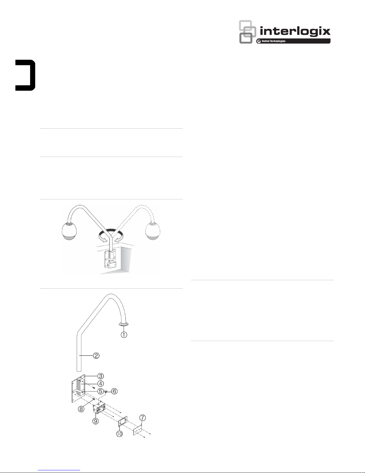
Figure 1: Mount positions out from a building and in above a roof
Figure 2: Package contents
1. Collar
2. Swing arm
3. Mounting plate
(fasteners not provided)
4. Mounting socket
5. Safety U bracket
6. Chase nipple (0.75 in.
conduit)
7. Junction box cover
(fasteners provided)
8. Pivot locking screws
9. Junction box (fasteners
provided)
10. Gasket
Product contents
• The swing arm
• Mounting plate (fasteners not provided)
• Safety U bracket
• Junction box (fasteners provided)
• Chase nipple (3/4 in. conduit)
• Gasket
• Junction box cover (fasteners provided)
Installation
Installation involves installing the mounting plate, installing the
swing arm, feeding the interconnect cables through the mount,
and installing the junction box.
Caution: For all installations, heed these cautions:
• Complete all installation steps before supplying power to
the PTZ.
• To ensure proper operation of a PTZ, install the mount
level.
• For safety, the mounting surface, hardware, and
procedure used for securing the PTZ must support the
weight of the PTZ, mount, cables, and any structural or
environmental vibration according to local codes.
Installing the mounting plate
1. Remove the junction box from the mounting plate
(Figure 2 above).
2. Using the mounting plate as a template, place it level
against the mounting surface and mark the position of the
mounting holes (Figure 3 on page 2). Use all six mounting
holes, if extra support is needed for your installation.
Page 2
2 / 3 P/N 1053528-EN • REV A • ISS 16JUL18
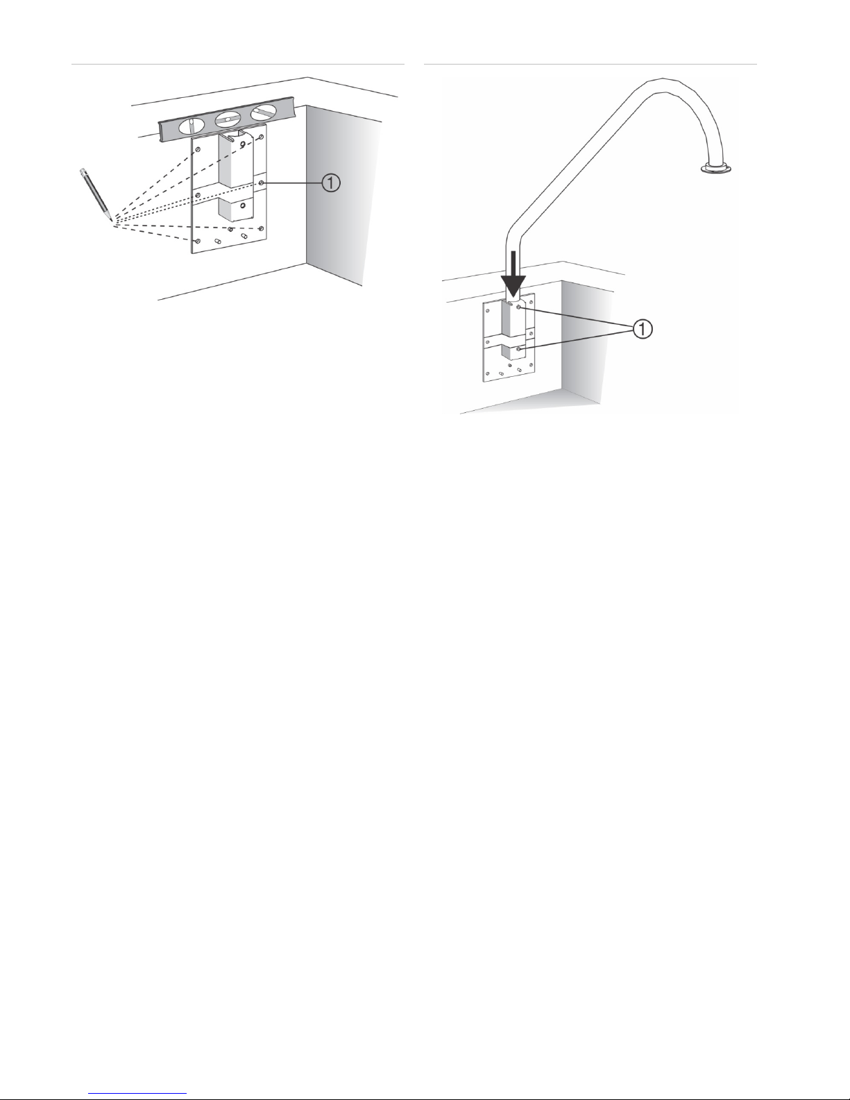
Figure 3: Marking the mounting holes
1. Middle holes are for
extra support.
2. Following all local codes, drill and prepare the mounting
holes.
3. Orient the mounting plate such that the socket is up and
the junction box is down (Figure 1 on page 1).
4. Securely fasten the mounting plate to the mounting
surface with the appropriate fasteners. Before installing
anchors into the middle holes, place the safety U bracket
on top of the mounting socket, aligning the holes in the
safety U bracket with the middle holes on the mounting
plate.
5. If needed, seal all mounting holes so that no moisture can
leak into the mounting surface.
Installing the swing arm
See Figure 4 below and do the following:
1. Slide the swing arm down into the mounting socket of the
mounting plate.
2. Position the arm such that the collar is accessible from the
rooftop for mounting the housing.
3. Temporarily tighten the pivot locking screws on the arm,
while you continue installing the mount.
Figure 4: Installing the swing arm
1. Pivot locking screws
Installing the interconnect cables and
junction box
1. Feed the interconnect cables through the junction box, the
chase nipple of the junction box, and up through the swing
arm (Figure 5 on page 3).
• Pull enough extra cable to make connections. You
can always cut off unneeded length later.
• Do not terminate the cables yet. Otherwise, they will
not fit through the dust seal of the housing.
2. Ensure that the parallel sides of the chase nipple are
aligned with the front and back of the top of the junction
box (Figure 5 on page 3). Otherwise, the chase nipple
may catch on the lower lip of the mounting socket.
Page 3

P/N 1053528-EN • REV A • ISS 16JUL18 3 / 3
Figure 5: Feeding the interconnect cables through the mount
1. Mounting plate
2. Mounting socket
3. Chase nipple
4. Junction box
5. Interconnect cables
6. Chase nipple
7. Attach the junction box to the mounting plate using the
fasteners provided (Figure 6 below).
Figure 6: Attaching the junction box to the mounting plate
8. Fit the gasket into the junction box cover and attach them
both to the junction box using the fasteners provided
(Figure 2 on page 1). Ensure that the gasket is properly
positioned. Otherwise, it will not seal the junction box.
9. Return to the PTZ installation manual, complete the
installation of the PTZ, and when done, loosen the pivot
locking screws, swing the arm to the desired position, and
securely tighten the pivot screws.
Legal and regulatory information
Trademarks and
patents
The trade names used in this document may be
trademarks or registered trademarks of the
manufacturers or vendors of the respective
products.
Manufacturer
Interlogix.
2955 Red Hill Avenue, Costa Mesa, CA 92626
5923, USA
Authorized EU manufacturing representative:
UTC Fire & Security B.V.
Kelvinstraat 7, 6003 DH Weert, The Netherlands
Certification
Product warnings
and disclaimers
THESE PRODUCTS ARE INTENDED FOR
SALE TO AND INSTALLATION BY QUALIFIED
PROFESSIONALS. UTC FIRE & SECURITY
CANNOT PROVIDE ANY ASSURANCE THAT
ANY PERSON OR ENTITY BUYING ITS
PRODUCTS, INCLUDING ANY “AUTHORIZED
DEALER” OR “AUTHORIZED RESELLER”, IS
PROPERLY TRAINED OR EXPERIENCED TO
CORRECTLY INSTALL FIRE AND SECURITY
RELATED PRODUCTS.
For more information on warranty disclaimers and
product safety information, please check
www.firesecurityproducts.com/policy/productwarning/ or scan the following code:
Contact
information and
manuals
/ tools /
firmware
For contact information and to download the
latest manuals, tools, and firmware, go to the web
site of your region.
Americas: www.interlogix.com
EMEA: www.firesecurityproducts.com
Manuals are available in several languages.
Australia/New Zealand: www.utcfs.com.au
 Loading...