

Interlogix TVP-6102, TVP-6101, TVP-6103 Installation Manual

TruVision
HD-TVI PTZ
Camera (TVP
-6101/
TVP
-6102/ TVP-6103)
Installation Guide
P/N 1073485-EN • REV B • ISS 08OCT18
Copyright
© 2018 United Technologies Corporation,
Interlogix is part of UTC Climate, Controls & Security, a unit
of United Technologies Corporation. All rights reserved.
Disclaimer
Information in this document is subject to change without
notice. No part of this document may be reproduced or
transmitted in any form or by any means, electronic or
mechanical, for any purpose, without the express written
permission of UTC Fire & Security Americas Corporation, Inc.
Trademarks and
patents
Trade names used in this document may be trademarks or
registered trademarks of the manufacturers or vendors of the
respective products.
Manufacturer
Interlogix
2955 Red Hill Avenue, Costa Mesa, CA 92626-5923, USA
Authorized EU manufacturing representative:
UTC Fire & Security B.V.
Kelvinstraat 7, 6003 DH Weert, The Netherlands
Certification
FCC compliance
Class A: This equipment has been tested and found to
comply with the limits for a Class A digital device, pursuant to
part 15 of the FCC Rules. These limits are designed to
provide reasonable protection against harmful interference
when the equipment is operated in a commercial
environment. This equipment generates, uses, and can
radiate radio frequency energy and, if not installed and used
in accordance with the instruction manual, may cause
harmful interference to radio communications. Operation of
this equipment in a residential area is likely to cause harmful
interference in which case the user will be required to correct
the interference at his own expense.
FCC conditions
This device complies with Part 15 of the FCC Rules.
Operation is subject to the following two conditions:
(1) This device may not cause harmful interference.
(2) This Device must accept any interference received,
including interference that may cause undesired operation.
ACMA compliance
Notice! This is a Class A product. In a domestic environment
this product may cause radio interference in which case the
user may be required to take adequate measures.
Canada
This Class A digital apparatus complies with CAN ICES-003
(A)/NMB-3 (A).
Cet appareil numérique de la classe A est conforme à la
norme CAN ICES-003 (A)/NMB-3 (A).
European Union
directives
This product and - if applicable - the supplied accessories
too are marked with "CE" and comply therefore with the
applicable harmonized European standards listed under
the EMC Directive 2014/30/EU, the RoHS Directive
2011/65/EU.
2012/19/EU (WEEE directive): Products marked with this
symbol cannot be disposed of as unsorted municipal
waste in the European Union. For proper recycling, return
this product to your local supplier upon the purchase of
equivalent new equipment, or dispose of it at designated
collection points. For more information see:
www.recyclethis.info.
2013/56/EU & 2006/66/EC (battery directive): This
product contains a battery that cannot be disposed of as
unsorted municipal waste in the European Union. See the
product documentation for specific battery information. The
battery is marked with this symbol, which may include
lettering to indicate cadmium (Cd), lead (Pb), or mercury
(Hg). For proper recycling, return the battery to your
supplier or to a designated collection point. For more
information see: www.recyclethis.info.
Product warnings
and disclaimers
THESE PRODUCTS ARE INTENDED FOR SALE TO AND
INSTALLATION BY QUALIFIED PROFESSIONALS. UTC
FIRE & SECURITY CANNOT PROVIDE ANY
ASSURANCE THAT ANY PERSON OR ENTITY BUYING
ITS PRODUCTS, INCLUDING ANY “AUTHORIZED
DEALER” OR “AUTHORIZED RESELLER”, IS
PROPERLY TRAINED OR EXPERIENCED TO
CORRECTLY INSTALL FIRE AND SECURITY RELATED
PRODUCTS.
For more information on warranty disclaimers and product
safety information, please check
www.firesecurityproducts.com/policy/product-warning/
or
scan the following code:

Contact information
and manuals/ tools/
firmware
For contact information and to download the latest
manuals, tools, and firmware, go to the web site of your
region.
Americas: www.interlogix.com
EMEA: www.firesecurityproducts.com
Manuals are available in several languages.
Australia/New Zealand: www.utcfs.com.au

Installation Guide 1
Content
Introduction 3
Product overview 3
HD-TVI 1080P PTZ Cameras 3
HD-TVI 1080P IR PTZ Cameras 3
Contact information and manuals/tools/firmware 3
Installation 4
Installation environment 4
Package contents 5
Pendant/Wall HD-TVI PTZ 5
Surface/Flush HD-TVI PTZ 7
Pendant/Wall IR HD-TVI PTZ 10
Cable requirements 11
DIP switch settings including selecting HD-TVI or Analog
output 12
HD-TVI PTZ 12
IR pendant/wall mount HD-TVI PTZ 16
Termination resistor settings 32
Camera description 35
IR illuminators 38
Mounting the outdoor HD-TVI PTZ 38
Mount the wall mount on the wall 38
Mount the camera on the wall mount 40
Flush mount the camera 42
Surface mount the camera 45

2 Installation Guide
Using the camera with a TruVision recorder or another
system 50
Programming 50
Change the video format (NTSC/PAL) 51
Menu tree 51
Specifications 53
TruVision Pendant/Wall HD-TVI PTZ Camera (TVP-6101) 53
TruVision Surface/Flush HD-TVI PTZ (TVP-6102) 53
TruVision Pendant/Wall IR HD-TVI PTZ (TVP-6103) 54

Installation Guide 3
Introduction
Product overview
This is the installation guide for TruVision HD-TVI PTZ
Camera (TVP-6101/ TVP-6102/ TVP-6103) models:
HD-TVI 1080P PTZ Cameras
TVP-6101 (32X, Pendant/Wall mount)
TVP-6102 (32X, Surface/Flush mount)
HD-TVI 1080P IR PTZ Cameras
TVP-6103 (32X, Pendant/Wall mount, IR)
The installation guide and configuration manual are available
on our web site.
Contact information and
manuals/tools/firmware
For contact information and to download the latest manuals,
tools, and firmware, go to the web site of your region.
Americas: www.interlogix.com
EMEA: www.firesecurityproducts.com
Manuals are available in several
languages.
Australia/
New Zealand:
www.utcfs.com.au

4 Installation Guide
Installation
This section provides information on how to install the
cameras.
Installation environment
When installing your product, consider these factors:
• Electrical: Install electrical wiring carefully. It should be
done by qualified service personnel. Always use a CE
certified power supply (24VAC) to power the camera. Do
not overload the power cord or adapter.
• Ventilation: Ensure that the location planned for the
installation of the camera is well ventilated.
• Temperature: Do not operate the camera beyond the
specified temperature, humidity or power source ratings.
Humidity is below 90%. For the outdoor cameras that
feature built-in heaters, the operating temperature range
is -30 to 65°C (-22 to149°F)
• Moisture: Do not expose the camera to rain or moisture
or try to operate it in wet areas. Turn the power off
immediately if the camera is wet and ask a qualified
service person for servicing. Moisture can damage the
camera and also create the danger of electric shock.
• Servicing: Do not attempt to service this camera
yourself. Any attempt to dismantle or remove the covers
from this product will invalidate the warranty and may
also result in serious injury. Refer all servicing to qualified
service personnel.
• Cleaning: Do not touch the sensor modules with fingers.
If cleaning is necessary, use a clean cloth with some
ethanol and wipe the camera gently. If the camera will not
Installation Guide 5
be used for an extended period of time, put on the lens
cap to protect the sensors from dirt.
Package contents
Check the package and contents for visible damage. If any
components are damaged or missing, do not attempt to use
the unit; contact the supplier immediately. If the unit is
returned, it must be shipped back in its original packaging.
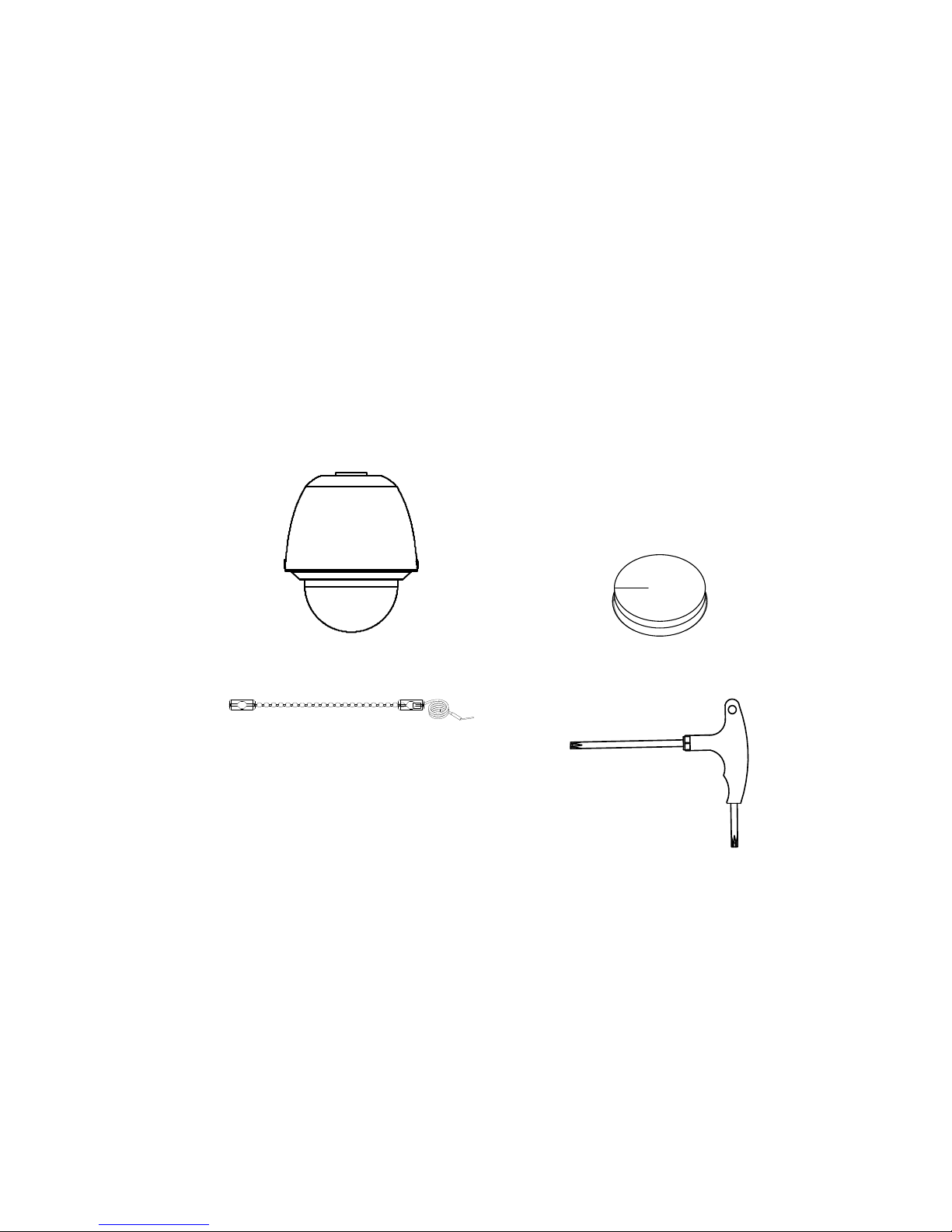
Pendant/Wall HD-TVI PTZ
• Camera
• Foam pad (3 pcs)
(Place it at the top of
the housing where the
harness exits).
• Safety lanyard
• Wrench (T20)
6 Installation Guide
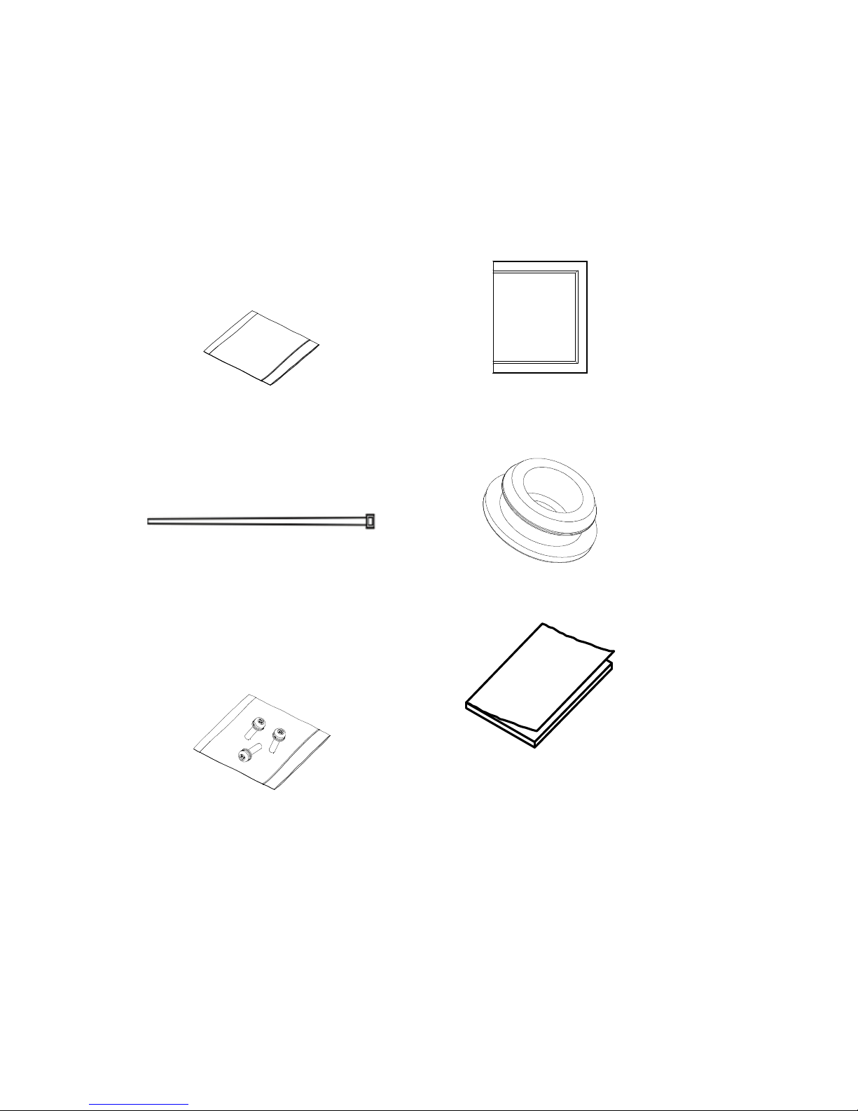
• Desiccant 1
(Two small bags.
Used as the spare
desiccant for the PTZ.
To use this desiccant,
place it inside the cup
base and tie it with the
zip tie below.)
• Desiccant 2
(One large bag. Used
to keep the two bags
of desiccant away
from moisture prior to
use).
• Zip tie (2 pcs)
(Used to tie the
desiccant 1 bags
inside the PTZ)
• Spare rubber plugs (2
pcs)
• Screws (3 pcs)
(Used to attach the
PTZ to the wall mount
bracket)
• Installation guide
Installation Guide 7
• Equipment Disposal
and Battery Disposal
documents
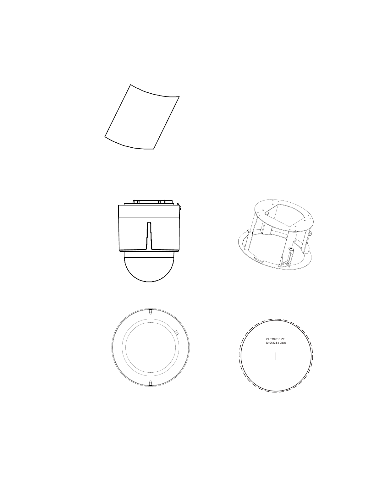
Surface/Flush HD-TVI PTZ
• Camera
• Housing ring
• Trim ring
• Drill template
(224 mm/8.82 in.)
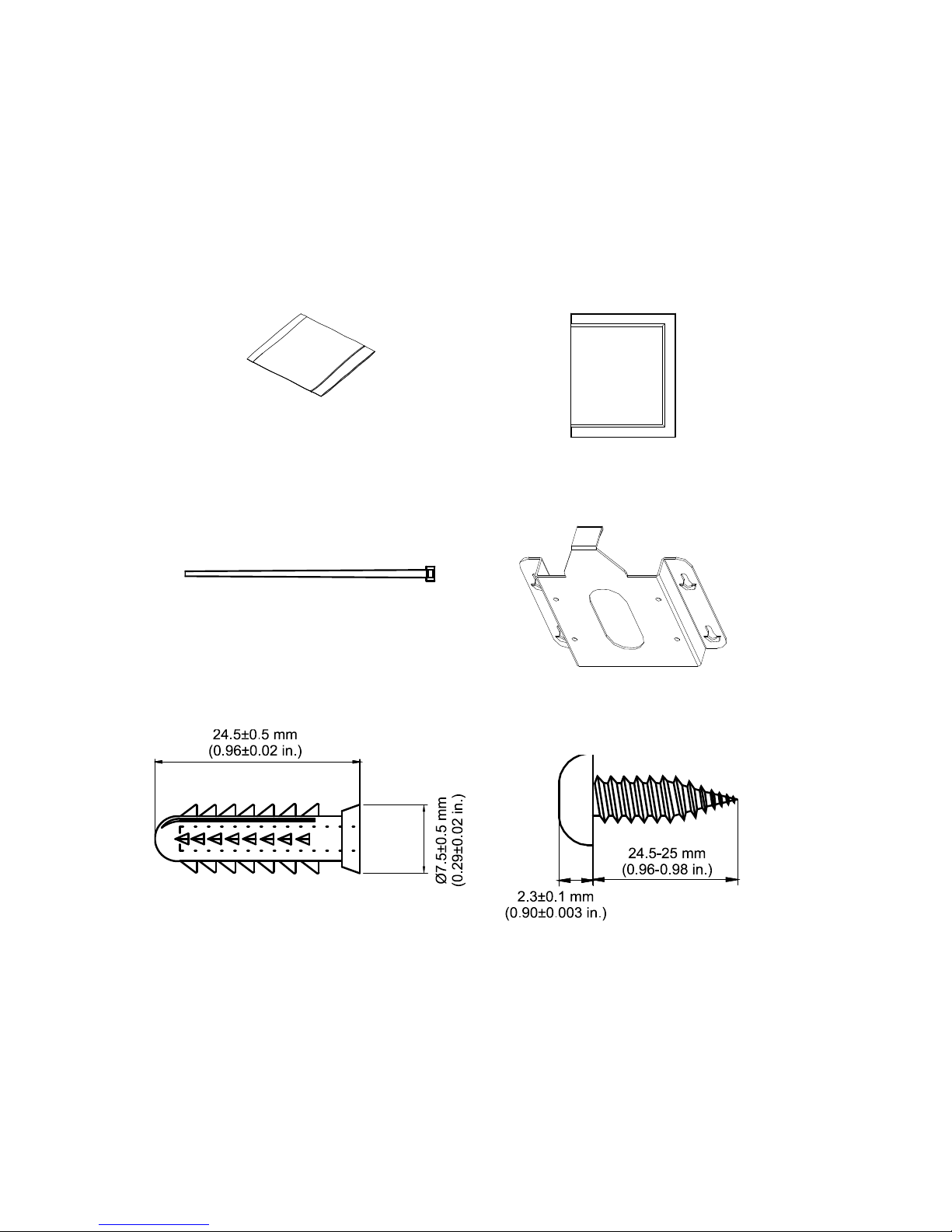
8 Installation Guide
• Desiccant 1
(Two small bags. Used as
the spare desiccant for the
PTZ. To use this
desiccant, place it inside
the cup base and tie it with
the zip tie below.)
• Desiccant 2
(One large bag.
Used to keep the
two bags of
desiccant away
from moisture prior
to use.)
• Zip tie (2 pcs)
(Used to tie the desiccant
1 bags inside the PTZ)
• Metal mounting
base
• Drywall anchors (4 pcs)
• Phillips screws (4
pcs)
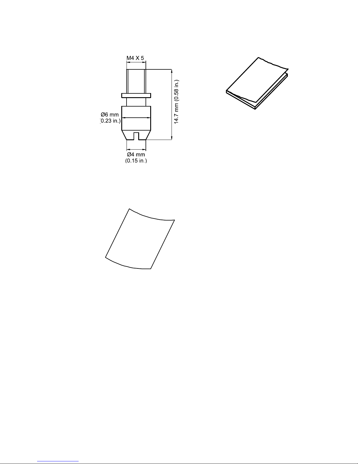
Installation Guide 9
• Fixation pin (4 pcs)
• Installation guide
• Equipment Disposal and
Battery Disposal
documents
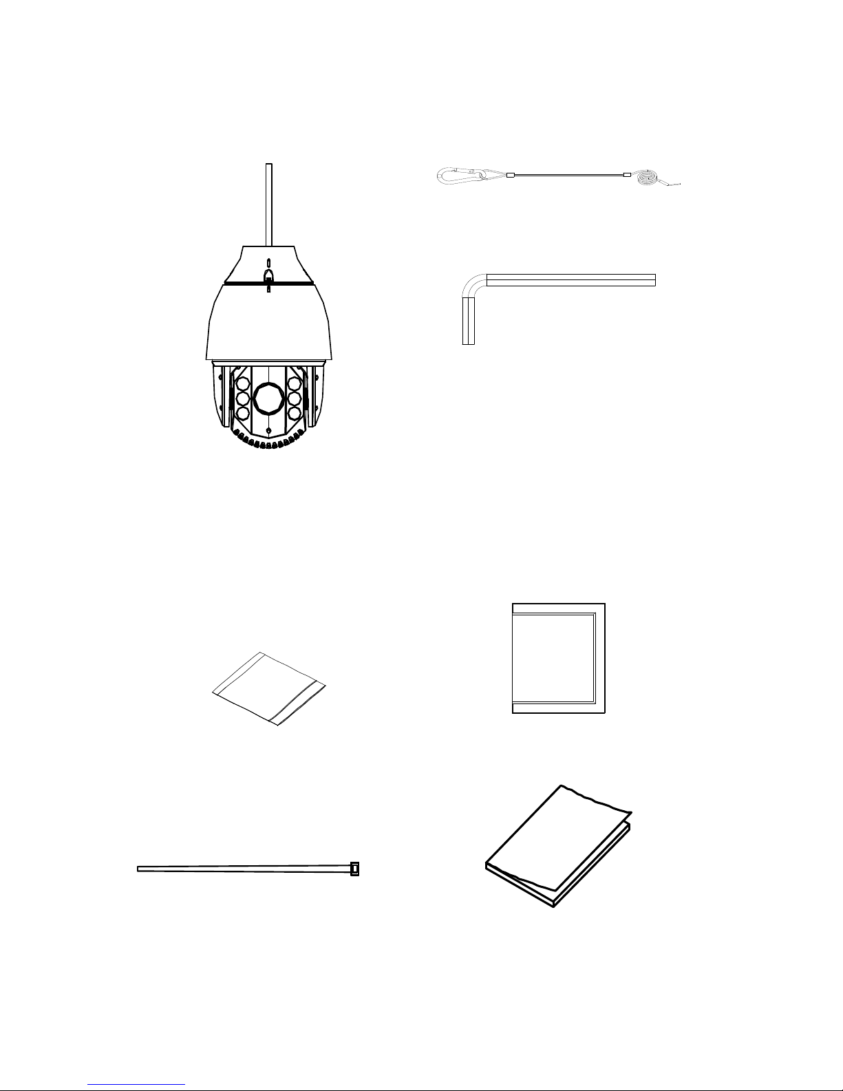
10 Installation Guide
Pendant/Wall IR HD-TVI PTZ
• Camera
• Safety lanyard
• Wrench (M4)
• Desiccant 1
(Two small bags. Used
as the spare desiccant
for the PTZ. To use this
desiccant, place it inside
the cup base and tie it
with the zip tie below.)
• Desiccant 2
(One large bag. Used
to keep the two bags of
desiccant away from
moisture prior to use).
• Zip tie (2 pcs)
(Used to tie the
desiccant 1 bags inside
the PTZ)
• Installation manual

Installation Guide 11
• Equipment Disposal and
Battery Disposal
documents
CAUTION: Use direct plug-in UL listed power supplies
marked Class 2/CE certified or LPS (limited power source) of
the required output rating as listed on the unit.
CAUTION: Risk of explosion if the battery is replaced by an
incorrect type. Dispose of used batteries according to the
instructions.
Cable requirements
Choose the video cable according to the transmission
distance. The minimum requirements for the coaxial video
cable are:
75Ω impedance
100% copper core conducting wire
95% weaving copper shield
RS-485 communication cable
24 VAC power cable
12 Installation Guide
DIP switch settings including selecting
HD-TVI or Analog output
HD-TVI PTZ
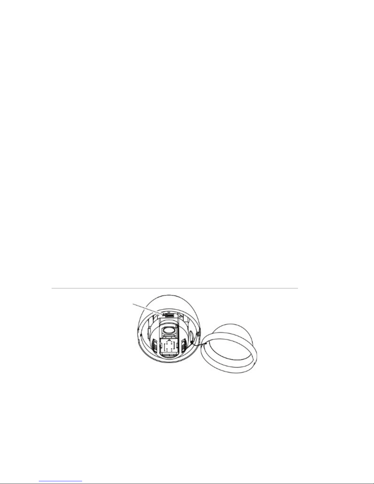
For pendant/wall PTZ cameras, access the DIP switch by
removing the rubber plugs on the two sides of the PTZ
housing and unscrewing the two screws inside. Then open the
bubble assembly, remove all three foam inserts and the plastic
protective lens cover (see Figure 1).
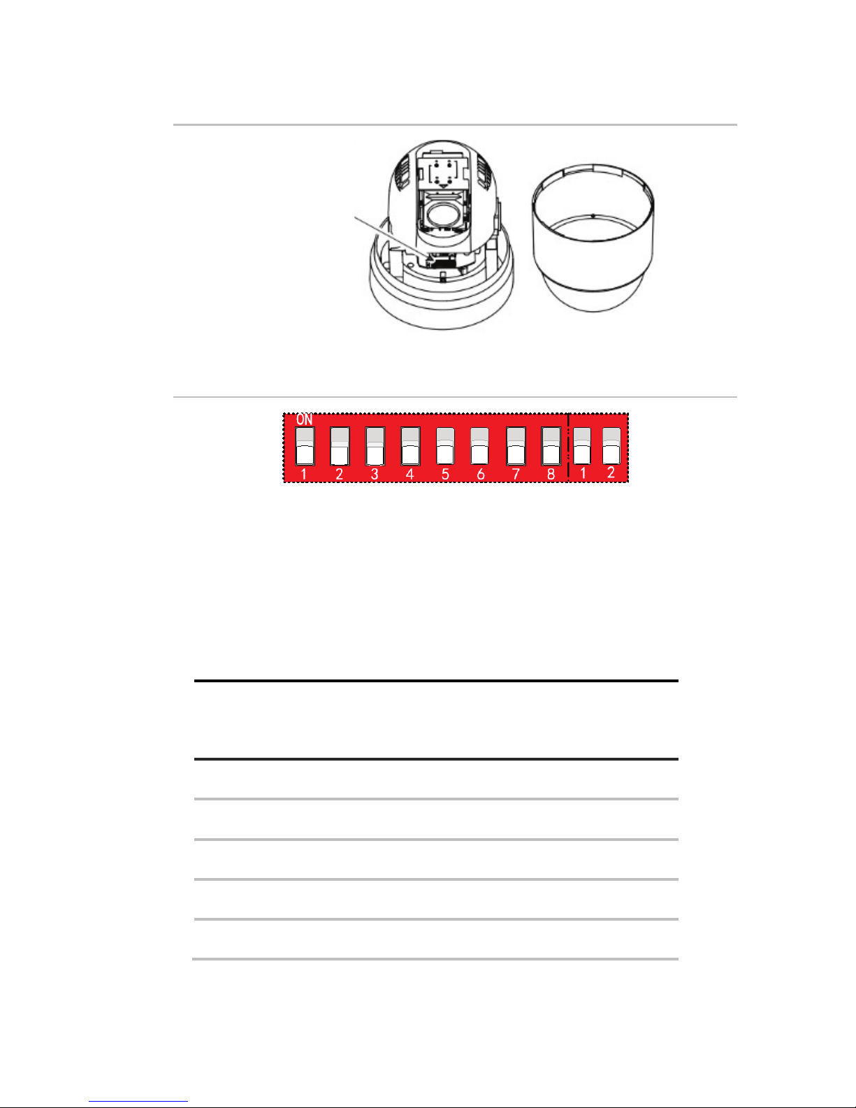
For surface/flush PTZ cameras, access the DIP switches by
rotating the housing (see Figure 2).
Use the DIP switch to set the address and baud rate for the
PTZ. Value ON=1 and OFF=0.
Use the SW1 switches from the first to the eighth positions to
set the address. Use the SW2 switches to set the baud rate.
Note: The default dome address is 0. The default baud rate is
2400.
Figure 1: DIP switch location for pendant/wall mount PTZ
DIP switch
Installation Guide 13
Figure 2: DIP switch location for surface/flush mount PTZ
DIP switch
Figure 3: Enlarged view of the DIP switch
Address settings
Use the SW1 switches from 1 to 4 to set the PTZ address.
Refer to Table 1 on setting the PTZ address to a specific
number.
Table 1: Set the dome address between 0 and 15
Dome
address
Switch no.
1 2 3 4
0 OFF OFF OFF OFF
1 ON OFF OFF OFF
2 OFF ON OFF OFF
3 ON ON OFF OFF
4 OFF OFF ON OFF

14 Installation Guide
Dome
address
Switch no.
1 2 3 4
5 ON OFF ON OFF
6 OFF ON ON OFF
7 ON ON ON OFF
8 OFF OFF OFF ON
9 ON OFF OFF ON
10 OFF ON OFF ON
11 ON ON OFF ON
12 OFF OFF ON ON
13 ON OFF ON ON
14 OFF ON ON ON
15 ON ON ON ON
Protocol settings
Use SW1 switches 5, 6 and 7 to set the PTZ protocol. Refer to
Table 2 below:
 Loading...