

Page 1

TVE-DEC12 User Manual
P/N 1073627-EN • REV C • ISS 27JUN19
Page 2

Copyright
©
2019 United Technologies Corporation.
Interlogix is part of UTC
Technologies Corporation.
Trademarks and
patents
T
trademarks of the manufacturers or vendors of the respective products.
Disclaimer
Information in this document is subject to change without
this document may be reproduced or transmitted in any form or by any
means, electronic or mechanical, for any purpose, without the express
written permission of UTC Fire & Security Americas Corporation, Inc.
Certification
Manufacturer
Interlogix
2955 Red Hill Avenue, Costa Mesa, CA 92626
Authorized EU manufacturing representative:
UTC Fire & Security B.V.
Kelvinstraat 7, 6003 DH Weert, The Netherlands
FCC compliance
Class B:
limits for a Class B digital device, pursuant to part 15 of the FCC Rules.
These limits are designed to provide reasonable protection against harmful
interference in a residential installation. T
and can radiate radio frequency energy and, if not installed and used in
accordance with the instructions, may cause harmful interference to radio
communications.
There is no guarantee that interference will not occur in a pa
installation. If this equipment does cause harmful interference to radio or
television reception, which can be determined by turning the equipment off
and on, the user is encouraged to try to correct the interference by one or
more of the followin
•
•
•
•
FCC conditions
This device complies with Part 15 of the FCC Rules. Operation is subject to
the following two conditions:
(1) This device may not cause harmful interference.
(2) This Device must accept any interf
interference that may cause undesired operation.
European Union
directives
12004/108/EC (EMC directive):
Corporation, Inc
essential requirements and other relevant provisions of Directive
2004/108/EC
2012/19/EU
be disposed of as unsorted municipal waste in
proper recycling, return this product to your local supplier upon the
purchase of equivalent new equipment, or dispose of it at designated
collection points. For more information see: www.recyclethis.info.
Climate, Controls & Security, a unit of United
All rights reserved.
rade names used in this document may be trademarks or registered
notice. No part of
-5923, USA
This equipment has been tested and found to comply with the
his equipment generates, uses,
g measures:
Reorient or relocate the receiving antenna.
Increase the separation between the equipment and receiver.
Connect the equipment into an outlet on a circuit different from that to
which the receiver is connected.
Consult the dealer or an experienced radio/TV technician for help.
., declares that this device is in compliance or with the
(WEEE directive): Products marked with this symbol cannot
rticular
erence received, including
Hereby, UTC Fire & Security Americas
the European Union. For
Page 3

Product warnings and
disclaimers
THESE PRODUCTS ARE INTENDED FOR SALE TO AND
INSTALLATION BY QUALIFIED PROFESSIONALS. UTC FIRE &
SECURITY CANNOT PROVIDE ANY ASSURANCE THAT ANY PERSON
OR ENTITY BUYING ITS PRODUCTS, INCLUDING ANY “AUTHORIZED
DEALER” OR “AUTHORIZED RESELLER”, IS
EXPERIENCED TO CORRECTLY INSTALL FIRE AND SECURITY
RELATED PRODUCTS
For more information on warranty disclaimers and product safety
information, please check www.firesecurityproducts.com/policy/product
warning/ or scan the following c
Contact information
and manuals
For contact information and to download the latest manuals, tools, and
firmware, go to the web site of your region.
Americas: www.interlogix.com
EMEA: www.firesecurit ypr o duct s.c om
Manuals are available in several
Australia/New Zealand: www.utcfs.com.au
PROPERLY TRAINED OR
.
-
ode:
languages.
Page 4

Page 5

Content
Important information 3
Limitation of liability 3
Advisory messages 3
Introduction 4
Package contents 4
Key features 4
First-time use 4
Default network settings 5
Tips on creating a strong password: 5
Accessing the web browser 5
Device manager network settings 6
Product description 7
Hardware 7
Video wall description 8
Configuration menu tree 9
System configuration 10
System settings 10
Maintenance 11
User management 12
Network configuration 14
TCP/IP settings 14
DDNS settings 15
HTTPS settings 16
Decoding configuration 18
Stream configuration 18
Transparent channel 18
Synchronous Output S etti ng s 19
Display options 20
Security control 21
Configuring the video wall 22
Video wall layout 22
Monitor resolutions 23
Add, modify or delete video streams 24
Using the decoder 28
Add device streams in the monitor s 28
Adjust the size of a stream tile 28
Select a predefined layout 29
Freely position a video tile 30
TVE-DEC12 User Manual 1
Page 6

Set up scenes 31
Manage the decoding of a video tile 33
Set up a sequence of streams in a tile 33
Appendix: Supported devices 34
2 TVE-DEC12 User Manual
Page 7

Important information
Limitation of liability
To the maximum extent permitted by applicable law, in no event will UTCFS be liable
for any lost profits or business opportunities, loss of use, business interruption, loss of
data, or any other indirect, special, incidental, or consequential damages under any
theory of liability, whether based in contract, tort, negligence, product liability, or
otherwise. Because some jurisdictions do not allow the exclusion or limitation of liability
for consequential or incidental damages the preceding limitation may not apply to you.
In any event the total liability of UTCFS shall not exceed the purchase price of the
product. The foregoing limitation will apply to the maximum extent permitted by
applicable law, regardless of whether UTCFS has been advised of the possibility of
such damages and regardless of whether any remedy fails of its essential purpose.
Installation in accordance with this manual, applicable codes, and the instructions of the
authority having jurisdiction is mandatory.
While every precaution has been taken during the prepar ati on of this man ual t o ensur e
the accuracy of its contents, UTCFS assumes no responsibility for errors or omissions.
Advisory messages
Advisory messages alert you to conditions or practices that can cause unwanted
results. The advisory messages used in this document are shown and described below.
WARNING: Warning messages advise you of hazards that could result in injury or loss
of life. They tell you which actions to take or to avoid in order to prevent the injury or
loss of life.
Caution: Caution messages advise you of possible equipment damage. They tell you
which actions to take or to avoid in order to prevent the damage.
Note: Note messages advise you of the possible loss of time or effort. They describe
how to avoid the loss. Notes are also used to point out important information that you
should read.
TVE-DEC12 User Manual 3
Page 8

Introduction
The TruVision TVE-DEC12 is a H.264/H.265 IP video decoder that decodes IP video
streams and shows them on the connected monitors.
Based on a powerful DSP and a stable embedded system design, the TVE-DEC12
decoder provides a high resolution decoding function for live view from TruVision IP
cameras, digital video recorders, network video recorders and encoders.
Package contents
The TruVision TVE-DEC12 IP video decoder is shipped with the following items:
• TVE-DEC12 decoder
• Power adaptor
• Power cable
• Quick start guide
• User manual (available from our web sites)
Key features
The following key features are supported by the TVE decoder:
• Supports H.264 and H.265 compression
• Powerful decoding cap abil i ty:
2-channel video stream at 12MPX resolution, or
4-channel video stream at 8MPX resolution, or
10-channel video stream at 3MPX resolution, or
16-channel video stream at 1080P resolution
• Can simultaneously decode up to a maximum of 16 video streams
• Multiple video display outputs: You can decode different cameras on HDMI, VGA
and BNC outputs
• Compatible with Interlogix TruVision IP cameras, TruVision recorders and TruVision
encoders
• Supports ONVIF and RTSP strea ms
• Can be used as video wall with a HDMI, VGA and BNC monitors
• Integrated in TruVision Navigator (version 8.1 SP2)
First-time use
The decoder does not have an OSD display. All configuration and control is done via
the webpage.
4 TVE-DEC12 User Manual
Page 9
Default network settings
The default network settings are:
• IP address - 192.168.1.70
• Subnet mask - 255.255.255.0
• Gateway address - 192.168.1.1
• HTTP port: 80
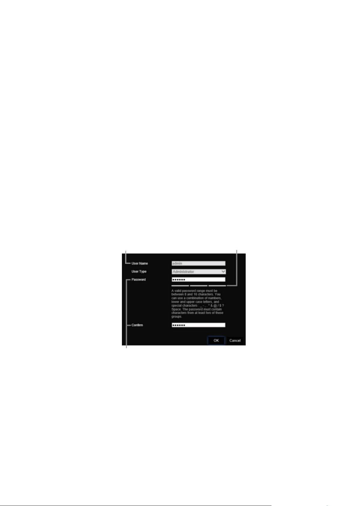
When you first start up the unit, the Activation window appears. You must define a high
security admin password before you can access the unit. There is no default password
provided.
Tips on creating a strong password:
• A valid password range must be between 8 and 16 characters. You can use a
combination of numbers, lower and upper case letters, and special characters: _ - , *
& @ / $ ? Space. The password must contain characters from at least two of these
groups.
• The password is case-sensitive so use a mixture of upper and lower case letters.
• Do not use personal information or common words as a password
User Name: It is always “admin”. It cannot
be changed. The bar showing password strength
Enter the new admin password and confirm it.
Accessing the web browser
The on-screen display menus are available in English and 10 other languages.
To access the web browser: (Internet Explorer only)
1. Open the web browser and select your language.
2. Enter the IP address of the decoder (for example, http://192.168.1.70). Press the
Enter key on the computer. The system displays the login window.
TVE-DEC12 User Manual 5
Page 10

3. Enter the user name (default: admin) and password to log into the system. The
decoder’s main page appears, which by default is Video Wall (see Figure 3 on page
8).
Device manager network settings
Use TruVision Device Manag er to fi nd and co n fig ur e the IP address and other
parameters of the device. This tool automatically identifies TruVision devices that
support “auto-discovery” anywhere on the network, even in different subnets.
To use the TruVision Device Manager:
1. Download the tool from our website.
2. Double-click the shortcut icon to open the tool. Click Device Manager to begin the
discovery process. The list of TruVision devices located on your network appears.
Note: The TruVision Device Manager can only detect devices that are on the same
LAN. The tool cannot detect devices placed on a VLAN.
3. Change the device settings as required. Click X on the top right corner when
completed.
6 TVE-DEC12 User Manual
Page 11
Link
Tx/Rx
HDMI
VGA
Audio out
Video out
Name
1.
2.
3
4
5.
6.
7.
8.
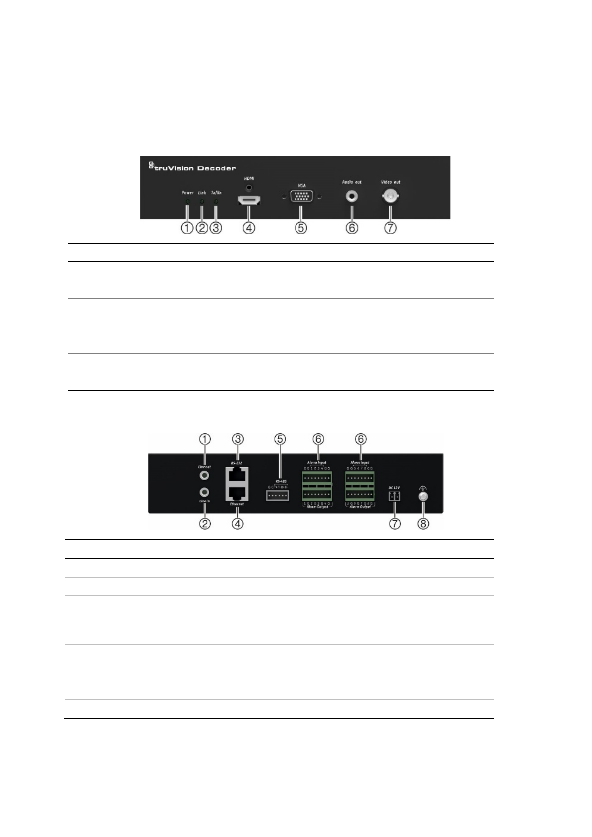
Product description
Hardware
Figure 1: Front panel
LED indicator Description
1. Power Power LED
2.
3.
4.
5.
6.
7.
Figure 2: Back panel
Line out Audio output, 3.5mm connector.
Network connection LED
Data transmitting/receiving status LED
HDMI output
VGA output
RCA Audio output
BNC decoding output
Description
Line in Audio input, 3.5 mm connector.
. RS-232 Connect to an RS-232 device, such as a computer.
. Ethernet Connect the 10M/100M/1000Mbps self-adap ti ve UT P
Ethernet port to a network.
RS-485 Connect to RS-485 serial port.
Alarm Input/Output Not applicable.
DC 12V Connect a 12 V power supply via a PSU.
GND Connect to ground.
TVE-DEC12 User Manual 7
Page 12
1.
2.
resolution and layout (number of rows and columns)
3.
4.
5.
6.
defined layouts with their streams so that they
7.
8
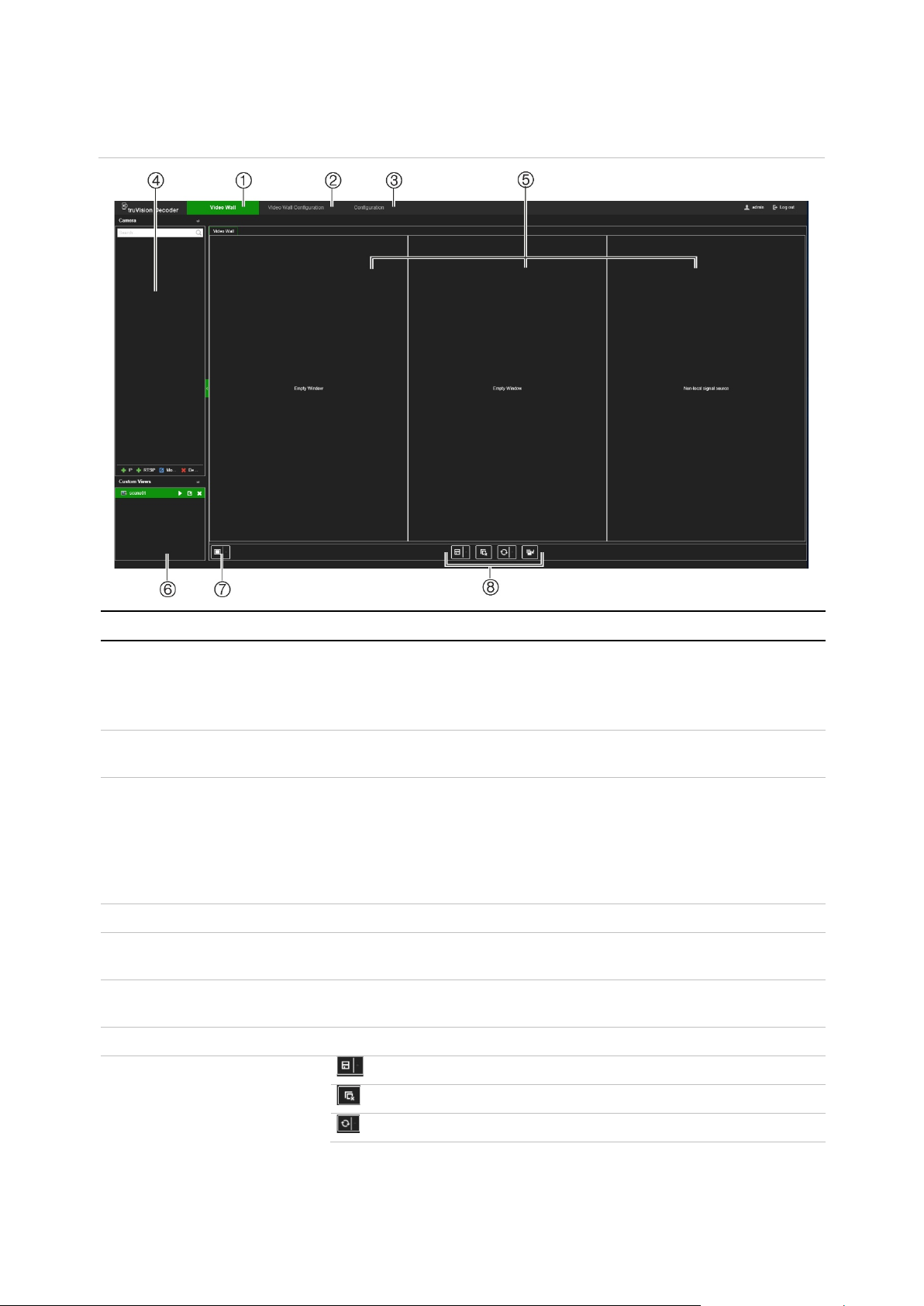
Video wall description
Figure 3: Video Wall webpage
Name Description
Video Wall menu Set up how you want the video wall to appear. Lets you select which
device is displayed on which monitor. Drag and drop devices from the
device tree to a monitor.
Note: Video images cannot be seen on the decoder webpage.
Video Wall Configuration
menu
Configuration menu Configure the general settings of the decoder. See Figure 4 on page 9
Device tree List of devices connected to the decoder.
Monitors The decoder can be used with HDMI, VGA and BNC monitors
Scene list Create a list of stored pre
Define the monitor
on the wall.
for a description of its menu tree.
For further information on configuring the decoder, see “System
configuration” on page 10, “Network configuration” on page 14,
“Decoding configuration” on page 18, and “Security control” on page
21.
simultaneously. Up to three monitors can be used.
can be quickly called up when needed.
Multiview Select the desired multiview.
. Shortcut toolbar Save the selected scene.
Delete all windows.
Refresh the screen.
8 TVE-DEC12 User Manual
Page 13

Name Description
The Send to Back button lets you switch the positions of
overlapping video tiles. Using the mouse, you can position the
streaming tiles to overlap. By clicking the ‘Send to the back layer’
button, the two tiles swap positions: the tile in the front moves to
the background and the tile in the background, moves to the
front.
Note: The Send to Back function is not available for a scene.
Configuration menu tree
Figure 4 below shows the structure of the Configuration menu tree.
Figure 4: Configuration menu tree
TVE-DEC12 User Manual 9
Page 14

System configuration
Log in and go to the Configuration menu to configure the general settings of the
decoder. The System men u has three main menus:
• System settings
• Maintenance
• User management
System settings
Use this menu to:
• Set and view the system Information, such as set the decoder name, and view the
version of the firmware and decoder.
• Set the parameters of the RS-232 communication port.
• Set the parameters of the RS-485 communication port.
To set up the system settings of the decoder:
1. Go to Configuration > System > System Settings.
2. To set up the decoder name and view the decoder’s system information, click the
System Information tab. Enter the decoder name, if desired.
3. To set up the RS-232 parameters, click the RS-232 tab. Select the desired RS-232
port, baud rate, data bit, stop bit, parity, flow control, and working mode parameters.
4. To set up the RS-485 parameters, click the RS-485 tab. Select the desired RS-485
camera number, baud rate, data bit, stop bit, parity, and flow control parameters.
5. Click the Save to save the changes.
10 TVE-DEC12 User Manual
Page 15

Maintenance
Use this menu to:
• Reboot the decoder: The administrator can reboot the decoder.
• Restore/Default the decoder: The administrator can reset the decoder to the
factory default settings. Network information such as IP address, subnet mask, and
gateway are not restored to factory default settings.
Note: Only the administrator can restore factory default settings.
• Import/Export configuration settings: The administrator can also export and
import configuration settings from the decoder. This is useful if you want to copy the
configuration settings to another device, or if you want to make a backup of the
settings.
• Update the decoder firmware: The administrator can update the decoder firmware
via the decoder web browser. Non-admin users can also upgrade the firmware if
they have upgrade permission. The decoder fi r mware can be updated using
TruVision Navigator (version 8.1 SP2). For further information, refer to the TruVisi o n
Navigator user manual . The firmware upgrade file is labeled tvedec12.dav.
Figure 5: Maintenance menu
To reboot the decoder:
1. Go to Configuration > System > Maintenance.
2. Click the Reboot button.
3. In the pop-up window, enter your admin password and click OK.
The system reboots.
To restore parameters to default factory settings:
1. Go to Configuration > System > Maintenance.
TVE-DEC12 User Manual 11
Page 16

2. To restore all parameters, except network settings, to default factory settings:
Click the Restore button. Enter the Admin password, click OK, and then click Yes to
confirm that you want to restore all parameters except network settings to default.
-orTo restore all parameters to default factory settings: Click the Default button.
Enter the Admin password, click OK, and then click Yes to confirm that you want to
restore all parameters to default.
The changes appear immediately.
To import and export files to and from the decoder:
1. Go to Configuration > System > Maintenance
2. To export the decoder’s configuration parameters to the PC, click the Export button.
To import configuration parameters from the PC, enter the location of the file to
select it and click Import.
To update the system firmware using the browser:
1. Download the latest firmware from our web site at:
Americas: www.interlogix.com
EMEA: www.firesecurityproducts.com
2. Go to Configuration > System > Maintenance
3. Select the firmware file and click Upgrade. Click Yes to begin the upgrade process.
4. When the upgrade process is completed, the decoder will reboot automatically.
User management
This menu allows you to create extra users and assign user access privileges. The
access privileges can be customized for each user’s needs.
Only an administrator can create and allocate access privileges to users.
To create a new user:
1. Go to Configuration > System > User Management.
12 TVE-DEC12 User Manual
Page 17

2. Click the Add button to add a new user.
3. Enter the user name and the Admin password.
4. Assign the user rights to this user for the operations that they can do remotely.
Select one or more of the following rights:
• Select All: Select all the options.
• Remote Parameter Set ti ng s: Remotely configure parameters and import
configuration.
• Remote Upgrade: Remotely upgrade the decoder firmware.
• Remote Reboot: Remotely reboot the recorder.
When no options are selected, the user cannot change any configuration setting, but
can drag/drop streams from the tree to the monitors in the Video Wall screen.
5. Click OK.
To modify a user:
1. Go to Configuration > System > User Management.
2. Click the Modify button.
3. Make the desired changes, such as change the password user rights.
4. Click OK.
To delete a user:
1. Go to Configuration > System > User Management.
2. Select the desired user and click the Delete button.
3. Confirm your choice and click OK.
TVE-DEC12 User Manual 13
Page 18

Network configuration
The Network menu allows you to manage all network related aspects of the decoder
including general network settings, DDNS, NTP synchronization, email setup, UPnP
settings, FTP server setup, and IP a ddr es s filter.
TCP/IP settings
To configure the general network settings:
1. Go to Configuration > Network > TCP/IP.
2. Enter the required settings:
Enable DHCP: DHCP (Dynamic Host Configuration Protocol) is a protocol for
assigning an IP address dynamically to a device each time it connects to a network.
Select this check box if you have a DHCP server running and want your decoder to
automatically obtain an IP address and other network settings from that server. The
DHCP server is typically available in your router.
Default value is Disable.
IPv4 Address: Enter the address of the decoder. This is the LAN IP address of the
decoder. Default value is 192.168.1.70
IPv4 Subnet Mask: Enter the subnet mask for your network so the decoder will be
recognized within the network. Default value is 255.255.255.0.
IPv4 Gateway: Enter the IP address of your network gateway so the decoder will be
recognized within the network. This is typically the IP address of your router.
Consult your router user manual or contact your ISP to get the required information
on your gateway. Default value is 192.168.1.1.
Preferred DNS server: Enter the preferred domain name server to use with the
decoder. It must match the DNS server information of your router. Check your
router’s browser interface or contact your ISP for the information.
Alternate DNS server: Enter the alternate domain name server to use with the
decoder.
3. Click Save to save the settings.
14 TVE-DEC12 User Manual
Page 19

DDNS settings
DDNS servers allow you to connect to your decoder using a dynamic address. This
dynamic address needs to be registered with a DNS service. The DDNS setup menu
allows you to enable or disable DDNS and to configure it using ezDDNS, No-IP or
DynDNS.
Note: Some service providers block the default RTSP streaming port 554 used for
video streaming. So if you are not receiving video images over the internet, you may
need to change it to another value.
There are three ways to set up a DDNS account:
• ezDDNS: A free-of-charge service included with your decoder and fully managed
within the decoder interface. It is exclusive to TruVision products.
• DynDNS: A third-party service where users need to apply for a DynDNS account on
the Dyn.com website.
• No-IP: A third-party service where users need to apply for a no-IP account on the
no-ip.com website.
Caution: If you use the services of DynDNS or No-IP, your account user name and
password for these services will be sent to them in clear text format when you set up
your connection in the decoder.
To configure the DDNS settings:
1. Go to Configuration > Network > DDNS.
2. Select the Enable DDNS checkbox to enable this feature.
3. Select one of the DDNS types listed:
ezDDNS: Click the Get URL button. The URL address to access the unit is
displayed. If no host name is specified, the DDNS will allocate one automatically.
The maximum length for the host name field is 64 characters. This limit does not
include tvn-ddns.net. An example of a host name could be max 64c hars.tvnddns.net.
- or –
TVE-DEC12 User Manual 15
Page 20

DynDNS: Select DynDNS and enter the server address for DynDNS. In the decoder
domain name field, enter the do main nam e obtai n ed from the DynDNS web site.
Then enter your user name and password registered in the DynDNS network.
For example:
Server address: member s.dyndns.org
Domain: mycompany dv r . dyndns .or g
User name: myname
Password: mypassword
- or -
NO-IP: Enter server address (for example, dynupdate.no-ip.com). In the host name
field, enter the host obtained from the NO-IP web site. Then enter the user name
and password that are registered with the No-IP network.
4. Ask your ISP service provider for your DNS server address or look it up in the
browser interface settings of your router.
Go to Network and enter the preferred and alternate DNS server addresses as well
as the default gateway address.
5. Click Save to save the settings.
HTTPS settings
Using HTTPS (Hypertext Transfer Protocol Secure) is a secure protocol that provides
authenticated and encrypted communication. It ensures that there is a secure private
channel between the decoder and the PC.
You can create self-signed server certificates as well as request certified server
certificates to ensure your network security. For larger companies, a corporate
certificate might be available with the IT department.
Note: You must run Microsoft Internet Explorer as administrator.
To create a server certificate:
1. Go to Configuration > Network > HTTPS.
16 TVE-DEC12 User Manual
Page 21

2. Check Enable HTTPS.
Note: This only works if you have entered the address in the browser as HTTPS (as
in https://192.168.1.70)
3. Select the type of certificate you want:
• Create a self-sign ed cert if icate:
a) Select Create Self-Signed certificate.
b) Click Create. The Create pop-up window appears.
c) Enter the country, hostname/IP address, and days of validity (there are more
parameters, but you do not need to add anything to them) and click OK.
d) A screen appears showing certificate information. Click Save.
- or –
• Create a certificate request and continue with the certificate installation:
a) Select Create the certificat e request first and continue the installation.
b) Click Create to create the certificate request and then click Download. Click
Save to save the certificate in the desired folder and then submit it to a
trusted certificate authority for signature.
c) When you receive the signed certificate, upload it to the decoder. Click
Browse to locate the certificate file and then click Install.
- or –
• If you already have a certified certificate:
a) Select Signed certificate is available, start the installation directly.
b) Click Browse to locate the certificate file and then click Install.
4. Click Save to save the settings.
TVE-DEC12 User Manual 17
Page 22

Decoding configuration
This menu contains settings that influence the decoding behavior, such as
automatically switching between main and substream, configuring transparent
channels, synchronizing video outputs, and defining what appears on the monitors
when decoding stops.
Stream configuration
The stream configuration setting allows the decoder to switch automatically between
main and substream when the resource limit of the decoder is reached.
To set up the stream configuration:
1. Go to Configuration > Decoding Configuration > Stream Configuration
2. Select the checkbox Auto-Switc h Stream Type to enable auto swit ching between
main stream and substream
3. Click Save to save the settings.
Transparent channel
The transparent channel needs to be configured to allow the data to be transmitted
between the encoder and decoder.
To configure the transparent channel
1. Go to Configuration > Decoding Configuration > Transparent Channel.
18 TVE-DEC12 User Manual
Page 23

2. Select the desired transparent channel from the list to configure.
3. Click Modify to modify the parameters of the selected transparent channel.
4. Under Local Serial Port and Remote Serial Port select either RS-485 or RS-232.
Local Serial Port: The serial port used as the transparent channel by the decoder.
Remote Serial Port: The serial port used as the transparent channel by the
encoding device.
5. Click Save to save the settings.
Synchronous Output Settings
Use this menu to synchronize all video outputs of the decoder.
To configure Synchronous Output Settings
1. Go to Configuration > Decoding Configuration > Synchronous Output
Settings.
TVE-DEC12 User Manual 19
Page 24

2. Click Enable Sync Out to enable the synchronization of all outputs. A message box
pops up saying that all outputs will be synchronized after the screen goes black
momentarily.
3. Click OK to confirm the settings.
Display options
Use the Display Options menu to define what appears on the monitors when decoding
stops.
To set up the display options:
1. Go to Configuration > Decoding Configuration > Display Options.
2. Select Blank Screen or Last Frame to be display ed w hen decodi ng ends .
Blank Screen: If selected, the screen becomes blank when the decoding ends.
Last Frame: If selected, the screen will show the last frame when the decoding
ends.
3. Select No Network Signal or Last Frame to be displayed when streaming fails .
No Network Signal: If selected and streaming fai ls, the screen will show a message
stating that there is no network signal .
Last Frame: If selected, the screen will show the last frame when streaming fails.
4. Click Save to save the settings.
20 TVE-DEC12 User Manual
Page 25

Security control
Use the Security Control menu to enable/disable SSH, HTTPS, network discovery and
the webpage time out.
To set up the Security Control:
1. Go to Configuration > Decoding Configuration > Securit y Control.
2. Make the necessary changes to the settings:
SSH: It can be enabled and disabled.
Multicast discovery: Enable/disable multicast discovery. This feature allows you to
enable/disable the discovery of the decoder on the LAN network by TruVision
Device Manager.
Webpage time out: Enable/disable webpage time out. Enabling this feature will
automatically log out the user after five minutes of inactivity.
TVE-DEC12 User Manual 21
Page 26

Configuring the video wall
The decoder can be used with HDMI, VGA and BNC monitors simultaneously, allowing
you to create a vi deo wall. A video wall allows camera images (video tiles) to be
displayed on more than one monitor.
See Figure 3 on page 8 for a description of the video wall.
Video wall layout
You need to define the layout of the video wall depending on the physical setup of the
three monitors.
To setup the video wall layout:
1. Go to Video Wall Configuration.
2. Click the layout icon . The configuration window appears.
Enter the number of monitors installed horizontally (row) and vertically (column).
Click OK.
3. Assign each monitor to a position on the video wall layout.
From the tree on the left of the screen, drag and drop the selected monitor into the
desired monitor position.
22 TVE-DEC12 User Manual
Page 27

Monitor resolutions
You must define the resolution of every monitor.
Note: Output configuration mode is not used in this version of the decoder.
To setup the resolution for the VGA monitor:
1. Go to Configuration > Video Wall Configuration.
2. Right-click the VGA monitor and select Resolution Configuration.
Select one of the following VGA resolutions:
1024 x 768 @ 60Hz (XGA) 1920 x 1080@ 60Hz (1080P)
1280 x 1024 @ 60Hz (SXGA) 1920 x 1080@ 50Hz (1080P)
1280 x 720 @ 50Hz (720P) 1690 x 1050 @ 60Hz (WSXGA)
To setup the resolution for the HDMI monitor:
1. Go to Configuration > Video Wall Configuration.
2. Right-click the HDMI monitor and select Resolution Configuration.
TVE-DEC12 User Manual 23
Page 28

Select one the following HDMI resolutions:
1024 x 768 @ 60Hz (XGA) 1920 x 1080 @ 50Hz (1080P)
1280 x 1024 @ 60Hz (SXGA) 1600 x 1200 @ 60 Hz (UXGA)
1280 x 720 @ 50Hz (720P) 1690 x 1050 @ 60Hz (WSXGA)
1280 x 720 @ 60Hz (720P) 3840 x 2160 @ 30Hz (4K)
1920 x 1080 @ 60Hz (1080P)
If the HDMI monitor is a LED monitor, select LED and the resolution, and define th e
width and height.
To setup the resolution for the BNC monitor:
1. Go to Configuration > Video Wall Configuration.
2. Right-click the BNC monitor and select Resolution Configuration.
Add, modify or delete video streams
The decoder does not have a discovery tool for finding cameras, encoders, or recorders
on the network. The channel information needs to be entered manually.
Note: The decoder can simultaneously decode up to a maximum 16 video streams.
To add a stream to the decoder:
1. Go to Video Wall. (See Figure 3 on page 8 for an example of this window.)
2. Click + IP to add a TruVision IP camera, an ONVIF camera, an encoder channel, or
a recorder channel.
24 TVE-DEC12 User Manual
Page 29

3. Click + RTSP to add a RTSP stream of a device.
To add a TruVision IP camera, ONVIF camera, or encoder/recorder channel:
1. Click in the Video Wall window. The +IP Add window appears:
2. Enter the information for the device:
• Device Name: Enter a meaningful name for the stream. The text box cannot be
left empty.
• IP Address: Enter the IP address for the device.
• Port: Enter the command port the device (default: 8000); for ONVIF devices,
enter port 80
• User Name: Enter the user name to access the device
• Password: Enter the password to access the device
• Transmission Protocol: Select the appropriate transmission protocol (TCP or
UDP)
• Stream Type: Select the desired stream type (main stream, substream, or third
stream (if available)).
• Area Name: Every device needs to be assigned to an area. An area can be the
logical group to which this device belongs (For example: a site name, a floor
number,…). To create an Area, click the + button, enter the area name, and
then click Save.
• Device Manufacturer: Select TruVision or ON VIF .
• Channel Number: Enter the highest channel number o f the dev i c e.
For a normal camera, the channel number will be 1.
For an encoder or recorder; enter the highest channel number of the device.
When using a hybrid recorder with both analog and IP cameras: When
adding a hybrid recorder, such as TVR 15HD, TVR 45HD or TVR 46, that has
both analog and IP cameras connected, the number of channels entered in this
field is not the highest channel number of the recorder. You must enter the sum
TVE-DEC12 User Manual 25
Page 30

of the total number of analog cameras that could be connected to the recorder
and the actual number of IP cameras connected.
For example, this is the window for adding a 16-channel TVR 15HD recorder
with 12 analog cameras and 4 IP cameras to the decoder. The channel number
to enter is 20 (16 is the maximum number of analog cameras that could be
connected plus 4 IP cameras ac tu al l y connected):
3. Click Next to continue.
4. The available channels window of the device appears. Select the channel numbers
that you want to add to the decoder and click OK.
The selected channels will then be added to the decoder and show up on the tree.
26 TVE-DEC12 User Manual
Page 31

To modify a TruVision IP camera, ONVIF camera, or encoder/recorder channel:
1. Click in the Video Wall webpage. The +IP Modify window appears. Change
the desired information and click OK.
To delete a TruVision IP camera, ONVIF camera, or encoder/recorder channel:
1. Click in the Video Wall webpage. The +IP Delete window appears. Confirm
that you want to delete the stream and click OK.
To add a RTSP stream:
1. Click +RTSP in the Video Wall webpage.
2. Enter the information for the stream
• Device Name: use a meaningful name for the stream
• URL: enter the valid RTSP URL stream for the device, includi ng the user na me
and password
• Area Name: select an area na me fro m the drop-down list or create a new area
name (see above)
Check the documentation of the device for the correct RTSP URL.
TVE-DEC12 User Manual 27
Page 32

Using the decoder
Once you have set up the devices/streams on the monitors (see “Configuring the video
wall” on page 22), you can then adjust where and how the video tiles appear on screen.
Add device streams in the monitors
You can easily add device streams to the monitors.
To add device streams to the monitors:
1. Go to Video Wall.
2. Drag and drop a device from the tree on to the desired monitor. By default, the
stream will be displayed in full screen mode.
Note: You cannot add more than three streams in full screen mode to one monitor.
If needed, resize the stream tile to be able to add more str ea ms.
Note: Video images cannot be seen on the decoder window. Only the name of the
stream will appear.
3. Adjust the size of the stream tile as required. See the next section for instructions.
Adjust the size of a stream tile
When you click on a stream, the selected video tile is framed by a red rectangle. You
can change the size of the rectangle by pressing the left mouse button on the rectangle
and then dragging the mouse until the tile is the desired size (see Figure 6 on page 29).
28 TVE-DEC12 User Manual
Page 33

Figure 6: Resizing a video tile
One of the features of the video wall is that you can show one stream spread over
different monitors. To do this, extend the size of the rectangle over the two monitors
(see Figure 7 below).
Figure 7: Extending a video tile over two monitors
Select a predefined layout
There are some predefined layouts av ai l abl e that y ou can s elec t for eac h mo nit or. The
following layouts are available:
• Full screen
• 1x2
• 2x2
• 1+5
TVE-DEC12 User Manual 29
• 1+7
• 3x3
• 3x4
• 4x4
Page 34
To select a predefined layout:
1. Go to Video Wall.
2. Add a stream to a monitor. By default, the stream will be displayed in full screen
mode.
3. Select the stream so that you see the red rectangle.
4. Click the multiview button and select the desired layout.
Note: The maxim um number of streams that can be shown simultaneously on all
monitors is 16.
5. Once the desired layout is selected, you can assign streams to each video tile in the
layout.
Freely position a video tile
The decoder lets you freely position a video tile anywhere on another monitor screen.
This can be useful if, for example, you have two monitors located far apart. This
decoder feature lets you drag one or more video tiles from one monit or to the oth er
monitor so that you can easily observe the selected roaming tile on the other monitor.
See Figure 8 below for an example of the result.
Note: The roaming tile feature is not available for BNC monitors. It can only be used
with the HDMI and VGA monitors.
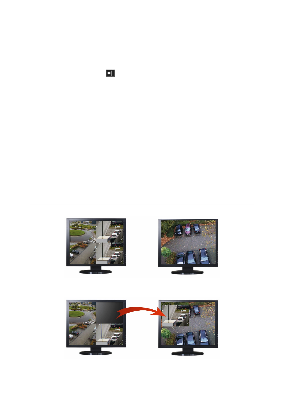
Figure 8: Example of using the roaming tile feature
Two monitors (HDMI and VGA) located far apart. One screen has multiview.
In the decoder, drag a nd dr op a video tile of one monitor to the other monitor. The result will look like this
on the monitors:
30 TVE-DEC12 User Manual
Page 35

To set up a roaming tile:
1. Go to Video Wall.
2. If you have not already done so, configure the video wall layout and add the
devices, such as camera or recorder streams. Define the multiview layout of the
selected video monitor .
3. Drag the desired tile from one of the monitor windows and place it anywhere on a
monitor window.
Note: By default the roaming tile is on top of the other tiles. To place it underneath,
click the ”Send to back layer” button.
4. Double-click the roaming tile to zoom in or out of the til e.
Set up scenes
A Scene is a custom view of the decoder. This feature allows you to store predefined
layouts with streams so that it is easy to call them up when needed. The output type is
not stored when storing a scene.
By default, Scene1 is always available and cannot be deleted. When first using the
decoder, Scene 1 is empty. There are no streams yet assigned to it.
You can configure up to a maximum of eight scenes.
Example:
Streams have been assigned to the monitors (in this example a multiview layout on the
left monitor and two full-screen recorder streams on the other monitors). See Figure 9
on page 32.
TVE-DEC12 User Manual 31
Page 36

Figure 9: Example of scenes assigned to three monitors
To save a scene:
1. Go to Video Wall.
2. To save this layout as a scene, click the Save/Save As button.
3. Enter the name of the scene to be sav ed and click OK.
The layout with streams is then saved as a scene:
To play, rename, or delete a scene:
1. Go to Video Wall.
2. To play a predefined scene, click the play button for the desired scene.
3. To rename a predefined scene, click the rename button for the desired scene
and enter the new name.
4. To delete a predefined scene, c l ick the delete button for the desired scene.
32 TVE-DEC12 User Manual
Page 37

Manage the decoding of a video tile
Right-click a stream tile to show the available commands for that tile. The list of options
displayed will depend on the device selected. The options available are:
• Stop decoding: Start/stop decoding.
• Show the decoding status: Show the decoding information for the selected
stream.
When you click More, a separate webpage will open and you can see the decoding
status of all streams.
• Turn on/off audio for the stream
• Decoding delay: Use this function to prioritize the quality or the fluency of the
stream. Select one of the options from the drop-down list:
• Enable Smart Information: with this function you can show the VCA information for
an IP camera in the stream.
Set up a sequence of streams in a tile
You can set up a sequence of streams on the monitor.
To set up a sequence:
1. Go to Video Wall.
2. Select a tile in the monitor (red rectangle will be seen around the tile).
3. Right-click the area name in the device tree and select Start Auto-Switch.
4. Setup the dwell time.
5. The sequence will start of all cameras of the area.
6. A small icon in the selected video tile on the webpage shows that the sequence is
running on the monitor.
It is a known limitation that the actual status of the sequence will not be displayed in the
webpage.
TVE-DEC12 User Manual 33
Page 38

Appendix: Supported devices
Cameras
Legacy TruVision IP cameras (TVx-Mx2xx)
Series 1 PTZ and fixed cameras
Series 2
Series 3
Series 4
Series 4 Stainless Steel
Encoders
TVE-400
TVE-800
TVE-1600
TVE-110
Series 5 (fixed and PTZ)
Series 6
360° cameras (TVF)
Panoramic wedge
Residential cameras (RS-xxxx)
Thermal cameras
TVE-410
TVE-810
TVE-1610
Recorders
TVR 41 series
TVR 42 series
TVR 11 series
TVR 12 series
TVR 12HD series
TVR 15HD series
TVR 44HD series
TVR 45HD series
TVR 46 series
TVN 10 series
TVN 11 series
TVN 21 series
TVN 22 series
TVN 70 series
TVN 71 series
34 TVE-DEC12 User Manual
 Loading...