

Page 1
TVE-DEC12 IP Video Decoder Quick
Link
Tx/Rx
HDMI
VGA
Audio out
Video out
Name
1.
2.
3
device, such as a computer.
4
5.
6.
7.
8.
Start Guide
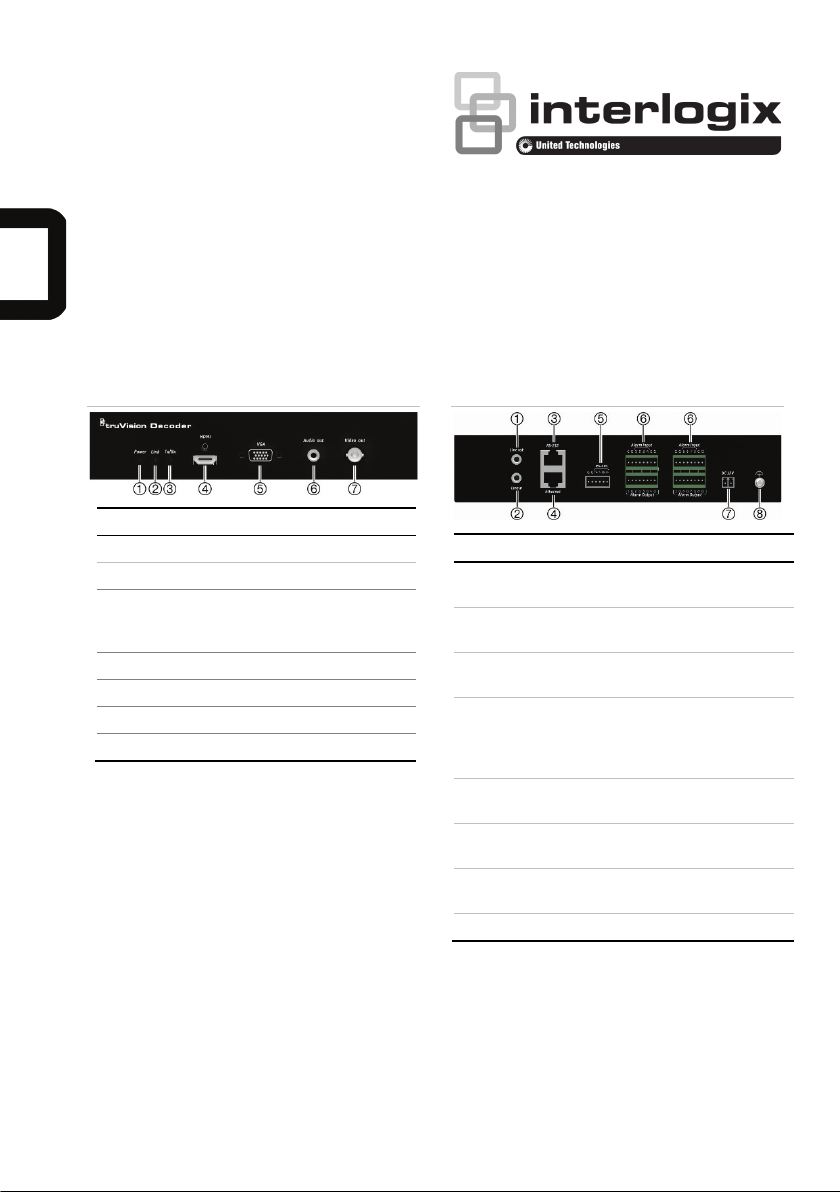
Figure 1: Front panel
LED indicator Description
1. Power Power LED
2.
Network connection LED
3.
4.
5.
6.
7.
HDMI output
VGA output
RCA Audio output
BNC decoding output
Data
transmitting/receiving
status LED
Figure 2: Back panel
Description
Line out Audio output, 3.5mm
Line in Audio input, 3.5mm
. RS-232 Connect to an RS-232
. Ethernet Connect the
RS-485 Connect to RS-485 serial
Alarm
Input/Output
DC 12V Connect a 12 V power
GND Connect to ground.
connector.
connector.
10M/100M/1000Mbps selfadaptive UTP Ethernet port
to a network.
port.
Not applicable.
supply via a PSU.
P/N 1073628-EN • REV A • ISS 08APR19 1
Page 2
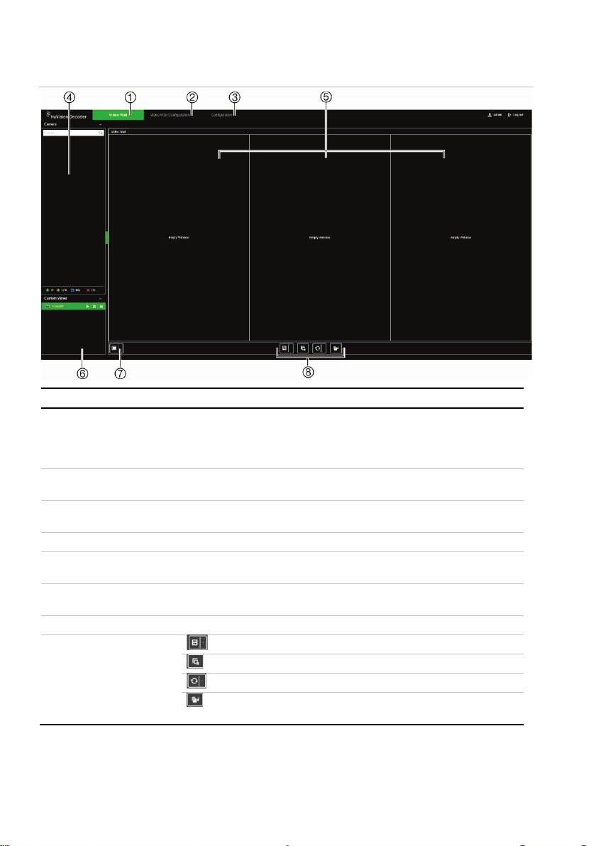
Figure 3: TVE Video Wall web page
1.
2.
3.
4.
5.
6.
7.
8
Name Description
Video Wall webpage Set up how you want the video wall to appear. Lets you select which device
Video Wall Configuration
webpage
Configuration webpage Configure the general settings of the decoder. See “Configuration” on page
Device tree List of devices connected to the decoder by their IP address or URL.
Monitors The decoder can be used with HDMI, VGA and BNC monitors
Scene list Create a list of stored pre-defined layouts with their streams so that they can
Multiview Select the desired multiview.
. Shortcut toolbar Save the scenes.
Stop decoding for all streams.
Refresh the screen.
The Send to Back button lets you switch the positions of overlapping
is displayed on which monitor. Drag and drop devices from the device tree to
a monitor.
Note: Video images cannot be seen on the decoder web page.
Define the monitor resolution and layout (number of rows and columns) on
the wall.
4.
simultaneously. Up to three monitors can be used.
be quickly called up when needed.
video tiles.
2 P/N 1073628-EN • REV A • ISS 08APR19
Page 3

Package contents
The TruVision TVE H.264 IP video decoder is
shipped with the following items:
• TVE-DEC12 decoder
• Power adaptor
• Power cable
• Quick start guide
Note: The Quick Start Guide and User
manual are available on our web sites:
Americas: www.interlogix.com
EMEA: www.firesecurityproducts.com
The manuals are available in several
languages.
Australia/New Zealand: www.utcfs.com.au
Activate the admin password
When you first start up the unit, the Activation
window appears. You must define a highsecurity admin password before you can
access the unit. There is no default password
provided.
A message will appear on-screen when the
unit has been activated.
Figure 4: Password activation window
User Name: It is always
“admin”. It cannot be
changed.
The bar showing
password strength
Tips on creating a strong password:
A valid password range must be
between 8 and 16 characters. You can
use a combination of numbers, lower
and upper case letters, and special
characters: _ - , * & @ / $? Space. The
password must contain characters from
at least two of these groups.
The password is case-sensitive so use a
mixture of upper and lower case letters.
The password must have between 8 and
16 characters.
Do not use personal information or
common words as a password.
Note: If you should forget your admin
password, please contact Technical Support
to reactivate the unit with a new password.
Network settings
Use TruVision Device Manager to find and
configure the IP address and other
parameters of the device. This tool
automatically identifies TruVision devices that
support “auto-discovery” anywhere on the
network, even in different subnets.
To use the TruVision Device Manager:
1. Download the tool from our website.
2. Double-click the shortcut icon to open
the tool. Click Device Manager to begin
the discovery process. The list of
TruVision devices located on your
network appears.
Note: The TruVision Device Manager
can only detect devices that are on the
same LAN. The tool cannot detect
devices placed on a VLAN.
3. Change the device settings as required.
Click X on the top right corner when
completed.
Enter the new admin password and confirm it.
P/N 1073628-EN • REV A • ISS 08APR19 3
Page 4

Before you start
Before accessing the browser, you need to
configure the network settings of the decoder.
Connect the decoder to the LAN, and connect
a computer to the same LAN as the decoder.
The decoder’s factory default user name is
admin. The decoder’s factory default IP
address is 192.168.1.70.
Accessing the web browser
The on-screen display menus are available in
English and 10 other languages.
To access the web browser:
1. Open the web browser and select your
language.
2. Enter the IP address of the decoder (for
example, http://192.168.1.70). Press the
Enter key on the computer. The system
displays the login window.
3. Enter the user name (default: admin) and
password to log into the system. The
decoder’s main page appears, which is
Video Wall by default (see Figure 3).
Restore the decoder
Import and export files
Upgrade the system firmware
User Management
Create extra users and assign user rights.
Network
Configure the network parameters, such as IP
address, DDNS and HTTPS settings.
Decoding Configuration
Stream configuration: Set up so the decoder
can automatically switch between main stream
and substream.
Transparent Channel: Define how to transfer
data between the encoder and decoder.
Synchronous Output Settings: Synchronize all
video outputs of the decoder.
Display Options: Define what appears on the
monitor screen when decoding stops.
Security Control
Enable/disable SSH, HTTPS, network
discovery, and the webpage time out.
Specifications
Configuration
Log in and go to the Configuration menu to
configure the general settings of the decoder.
It has four branches:
System
System settings
System Information: Displays the decoder
version.
Time Settings
RS-232: RS-232 communication port
parameters.
RS-485: RS-485 communication port
parameters.
Maintenance
Restart the decoder
Power supply 12 VDC
Consumption Max. 15W
Operating temperature
Operating humidity 10% to 90%
Dimensions
(W ×D × H)
Weight 1.12 kg (2.47 lbs.)
-10 to +55°C (14 to
131°F)
220 × 180 × 45 mm
(8.66 × 7.09 × 1.77
in.)
4 P/N 1073628-EN • REV A • ISS 08APR19
Page 5

Legal information
Copyright
Trademarks and
patents
Disclaimer
form or by any means, electronic or
Certification
European Union
directives
with this symbol, which may
include lettering to indicate
mercury (Hg). For proper recycling,
Product
warnings and
disclaimers
ANY “AUTHORIZED DEALER” OR
Contact
information and
manuals/ tools/
firmware
download the latest manuals, tools,
© 2019 United Technologies
Information in this document is
P/N 1073628-EN • REV A • ISS 08APR19 5
Corporation.
Interlogix is part of UTC Climate,
Controls & Security, a unit of
United Technologies
Corporation. All rights reserved.
The trade names used in this
document may be trademarks or
registered trademarks of the
manufacturers or vendors of the
respective products.
subject to change without notice.
No part of this document may be
reproduced or transmitted in any
mechanical, for any purpose,
without the express written
permission of UTC Fire & Security
Americas Corporation, Inc.
This product and - if applicable the supplied accessories too are
marked with "CE" and comply
therefore with the applicable
harmonized European standards
listed under the EMC Directive
2014/30/EU, the RoHS Directive
2011/65/EU.
2012/19/EU (WEEE directive):
Products marked with this symbol
cannot be disposed of as unsorted
municipal waste in the European
Union. For proper recycling, return
this product to your local supplier
upon the purchase of equivalent
new equipment, or dispose of it at
designated collection points. For
more information see:
www.recyclethis.info.
2013/56/EU & 2006/66/EC (battery
directive): This product contains a
battery that cannot be disposed of
as unsorted municipal waste in the
European Union. See the product
documentation for specific battery
information. The battery is marked
cadmium (Cd), lead (Pb), or
return the battery to your supplier
or to a designated collection point.
For more information see:
www.recyclethis.info.
THESE PRODUCTS ARE
INTENDED FOR SALE TO AND
INSTALLATION BY QUALIFIED
PROFESSIONALS. UTC FIRE &
SECURITY CANNOT PROVIDE
ANY ASSURANCE THAT ANY
PERSON OR ENTITY BUYING
ITS PRODUCTS, INCLUDING
“AUTHORIZED RESELLER”, IS
PROPERLY TRAINED OR
EXPERIENCED TO CORRECTLY
INSTALL FIRE AND SECURITY
RELATED PRODUCTS.
For more information on warranty
disclaimers and product safety
information, please check
www.firesecurityproducts.com/polic
y/product-warning/ or scan the
following code:
For contact information and to
and firmware, go to the web site of
your region.
Americas: www.interlogix.com
EMEA:
www.firesecurityproducts.com
Manuals are available in several
languages.
Australia/New Zealand:
www.utcfs.com.au
Page 6

 Loading...