


TVE-DEC11 IP Video Decoder Quick Start
LED indicator
P
Link
Tx/Rx
HDMI
VGA
Audio out
Video out
Item
1.
2.
3.
-
4.
232 device, such as a
5.
6.
7.
8.
Guide
• Quick start guide
Description
Figure 1: Front panel
Item
1.
2.
3.
4.
5.
6.
7.
Figure 2: Rear panel
ower The power LED
Network connection LED
Data transmitting/receiving status LED
HDMI output
VGA output
RCA Audio output
BNC decoding output
Description
• CD (includes the user manual and TruVision Device
Manager)
Network settings
Use TruVision Device Manager to find and configure the IP
address and other parameters of the device. This tool
automatically identifies TruVision devices that support “autodiscovery” anywhere on the network, even in different subnets.
The TruVision Device Manager tool can be found on the CD
shipped with the decoder.
To install the TruVision Device Manager:
1. Insert the CD in the computer’s CD/DVD drive.
2. Browse to the folder Tools and double-click the Setup file
located in the folder.
3. Following the instructions, select the folder where setup
will install the files then click Next.
4. The program requires a utility called WinPcap to be
installed on the computer. If it is already installed, go to
step 5. If the program is not installed, the WinPcap window
appears. Follow the on-screen instructions.
Name Description
Line out Audio output, 3.5mm connector.
Line in Audio input, 3.5mm connector.
Ethernet
RS-232
RS-485 Connect to RS-485 serial port.
Alarm Input Connect up to four alarm relay inputs.
Alarm Output Connect up to four alarm relay outputs.
DC 12V Connect a 12 V power supply via a PSU.
GND Connect to ground.
Connect the 10M/100M/1000Mbps self
adaptive UTP Ethernet port to a network.
Connect to an RScomputer.
Package contents
The TruVision TVE H.264 IP video decoder is shipped with the
following items:
• TVE-DEC11 decoder
• Power adaptor
• Power cable
5. The TruVision Device Manager Wizard appears. Click
Finish to complete its installation. The shortcut icon
appears on your desktop.
To use the TruVision Device Manager:
1. Double-click the shortcut icon to open the tool. Click
Device Manager to begin the discovery process. The list
of TruVision devices located on your network appears.
Note: The TruVision Device Manager can only detect
devices that are on the same LAN. The tool cannot detect
devices placed on a VLAN.
2. Change the device settings as required. Click X on the top
right corner when completed.
Before you start
Before accessing the browser, you need to configure the
network settings of the decoder. Connect the decoder to the
LAN, and connect a computer to the same LAN as the
decoder.
The decoder’s factory default user name is admin and the
password is 1234. The decoder’s factory default IP address is
192.168.1.70.
© 2015 United Technologies Corporation. All rights reserved. P/N 1072900A-EN • REV 1.0 • ISS 27JAN15
Interlogix is part of UTC Building & Industrial Systems, a unit of United Technologies Corporation. All rights reserved.
Accessing the web browser
Decoding Operation
Decode Mode
Decode Control
Decoding Status
Transparent Channel
Connection Status
Decoding Channel
Display Channel
Ch Enable/Disable
Picture Overlay
Dynamic Decoding
Sequence Decoding
Remote Playback
Display Control
Configuration
Device Properties
Time Settings
Network Settings
Serial Port Settings
Alarm Settings
Arming Time
User Management
Config File Import
/Export
RS-232 Port
RS-485 Port
Alarm Input
Alarm Output
General
DDNS
Telnet
The on-screen display menus are available in English and
Chinese.
To access the web browser:
1. Open the web browser and enter the IP address of the
decoder (for example, http://192.168.1.70). Press the
Enter key on the computer. The system displays the login
window.
2. Enter the user name (default: admin) and password
(default: 1234) to log into the system. The main page of
the decoder appears, which is Decoding Operation by
default (see Figure 3).
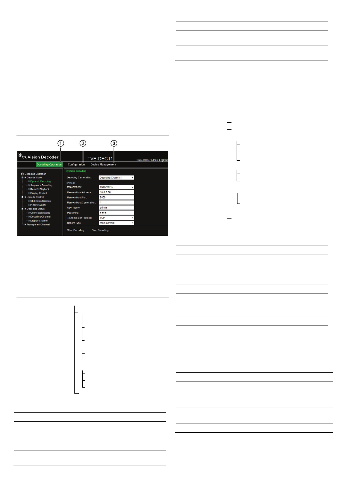
Figure 3: TVE decoder main page
Function Description
Decoding
Status
Transparent
Channel
Display the decoding channel status and video
output status.
Set up transparent data transmission between the
encoder and decoder.
Configuration
Use these menus to configure the decoder.
Figure 5: Menu tree of Configuration
1. Decoding Operation: Configures decoding resource, decoding
mode and video output.
2. Configuration: Configures device settings, network parameters,
alarm and user account.
3. Device management: Upgrades firmware, restores factory
default settings, and reboots the decoder.
Figure 4: Menu tree of the Decoding Operation
Table 2: Description of the Configuration menu tree
Function Description
Define the decoder name.
Device Properties
Time Settings Define the device time
Network Properties Define network settings.
Serial Port Settings Define the serial port properties.
Alarm Settings
Arming Time Define alarm schedules.
User Management
Config File Import/Export Import/export configuration files.
Display the decoder serial number and
firmware version.
Configure alarm input/output settings
and notification method.
Create, modify or delete users and
allocate user permissions.
Specifications
Power supply 12 VDC
Table 1: Description of the Decoding Operation menus
Function Description
Decode
Mode
Decode
Control
2 P/N 1072900A-EN • REV 1.0 • ISS 27JAN15
Select decoding channels and sequence.
• Configure playback on recorded files.
• Configure display channel, video format, output
resolution and display mode.
Enable/disable a decoding channel, scale video
output image, and configure picture overlay.
Consumption Max. 15W
Operating temperature -10 to +55 °C (14 to 131 °F)
Operating humidity 10% to 90%
Dimensions
(W ×D × H)
Weight 1.12 kg (2.47lbs)
220 × 180 × 45 mm
(8.66 × 7.09 × 1.77 in.)
Contact information
For contact information, see www.interlogix.com or
www.utcfssecurityproducts.eu.
 Loading...