

Page 1
TVE-DEC10 IP Video Decoder Quick Start
Guide
Description
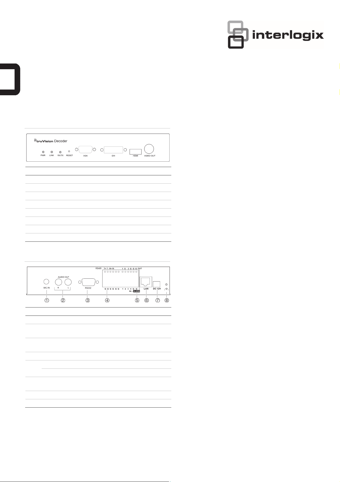
Figure 1: Front panel
LED indicator Description
PWR The power LED
LINK Network connection LED
RX/TX Data transmitting/receiving status LED
RESET Reset to factory default settings
VGA VGA decoding output
DVI DVI decoding output
HDMI HDMI decoding output
VIDEO OUT BNC decoding output
Figure 2: Back panel
Package contents
The TruVision TVE H.264 IP video decoder is shipped with the
following items: TVE-DEC10 decoder, power adaptor, power
cable, and CD (includes the user manual and TruVision Device
Finder).
Network settings
Use TruVision Device Finder to find and configure the IP
address and other parameters of the device. This tool
automatically identifies TruVision devices that support “autodiscovery” anywhere on the network, even in different subnets.
The TruVision Device Finder tool can be found on the CD
shipped with the decoder.
To install the TruVision Device Finder:
1. Insert the CD in the computer’s CD/DVD drive.
2. Browse to the folder TruVision Device Finder and doubleclick the Setup file located in the folder.
3. Following the instructions, select the folder where setup
will install the files then click Next.
4. The program requires a utility called WinPcap to be
installed on the computer. If it is already installed, go to
step 5. If the program is not installed, the WinPcap window
appears. Follow the on-screen instructions.
Item Name Description
1. MIC In Microphone input.
2. Audio Out Connect to an audio output device. R is right
channel, L is left channel.
3. RS-232 Connect to an RS-232 device, such as a
computer.
4. RS-485 Connect to RS-485 serial port.
5. Alarm Out Connect up to two alarm relay outputs.
Alarm In Connect up to four alarm relay inputs.
6. LAN Connect the 10M/100M/1000Mbps selfadaptive UTP Ethernet port to a network.
7. 12 VDC Connect a 12 V power supply via a PSU.
8. GND Connect to ground.
5. The TruVision Device Finder Wizard appears. Click Finish
to complete its installation. The shortcut icon appears on
your desktop.
Using the TruVision Device Finder
1. Double-click the shortcut icon to open the tool. Click Start
in the Start window to begin the discovery process. The
list of TruVision devices located on your network appears.
Note: The TruVision Device Finder can only detect
devices that are on the same LAN. The tool cannot detect
devices placed on a VLAN.
2. Change the device settings as required. Click Exit when
completed.
Note: You must reboot to activate the new IP address or
subnet mask.
Before you start
Before accessing the browser, you need to configure the
network settings of the decoder.
Connect the decoder to the LAN, and connect a computer to
the same LAN as the decoder.
© 2012 UTC Fire & Security Americas Corporation, Inc. 1 / 2 P/N 1072584B • REV 1.0 • ISS 16OCT12
Page 2
The decoder’s factory default user name is admin and the
A
A
A
p
Conf
g
password is 1234. The decoder’s factory default IP address is
192.168.1.70.
Accessing the web browser
The on-screen display menus are in English only.
To access the web browser:
1. Open the web browser and enter the IP address of TVE
decoder (for example, http://192.168.1.70). Press the
Enter key on the computer. The system displays the login
window.
2. Enter the user name (default: admin) and password
(default: 1234) to log into the system. The main page of
the TVE decoder appears.
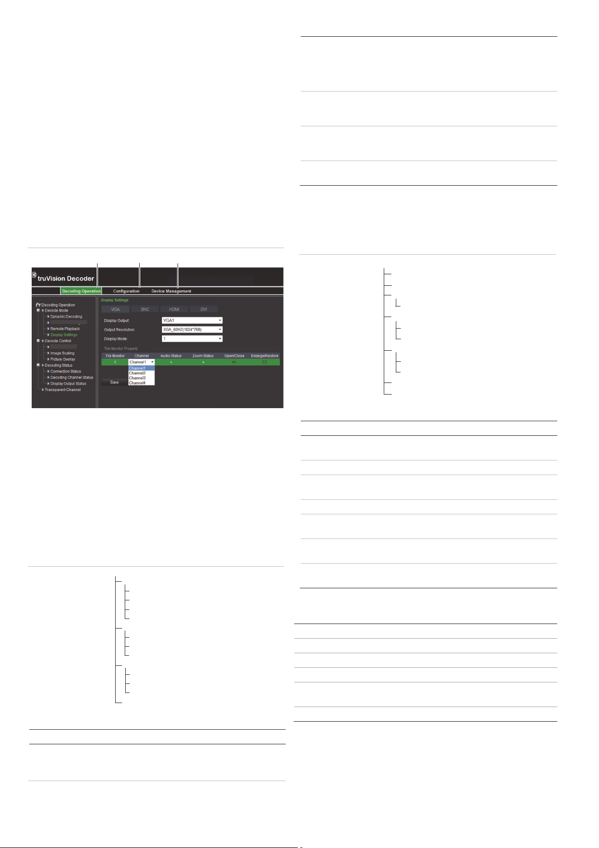
Figure 3: TVE decoder main page
Sequence Decoding
Ch Enable/Disable
1. Decoding Operation: Configures decoding resource, decoding
mode and video output.
2. Configuration: Configures device settings, network parameters,
alarm and user account.
3. Device management: Upgrades firmware, restores factory
default settings, and reboots the decoder.
TVE-DEC10
Decoder operation
Use these menus to define how the decoder operates. See
Figure 4 below.
Figure 4: Menu tree of Decoding Operation
Decoding Operation
Decode Mode
Dynamic Decoding
Sequence Decoding
Remote Playback
Display Settings
Decode Control
Ch Enable/Disable
Image Scaling
Picture Overlay
Decoding Status
Connection Status
Decoding Channel Status
Display Output Status
Trans
arent Channel
Table 1: Description of the Decoding Operation menu tree
Function Description
Decode mode Defines the parameters for:
- The channels to be decoded and their
sequencing mode.
- The encoder to be accessed to playback
recorded files as well as the name and playback
time of the recorded file.
- The display channel, video format, output
resolution and display mode
Decode control Defines the parameters for enabling/disabling a
decoding channel, scaling the video output
image, and overlaying a picture on the image.
Decoding status Defines the channel to be used for decoding as
well as view the decoding channel’s status and
configuration information.
Transparent channel Defines the parameters to transmit transparent
data between the encoder and decoder.
Configuration
Use these menus to configure the decoder.
Figure 5: Menu tree of Configuration
iguration
Device Properties
Time Settings
Network Parameters
Basic Network Settings
Serial Port Parameters
RS-232 Settings
RS-485 Settings
Alarm Parameters
Alarm Input Settings
Alarm Output Settings
Arming Time
Account Mana
Table 2: Description of the Configuration menu tree
Function Description
Device properties Defines the decoder name. Displays the
decoder serial number and firmware version.
Time settings Defines the time used by the decoder.
Network properties Defines the basic network settings of the
decoder.
Serial port settings Defines the serial port settings of the decoder.
larm parameters Defines the external alarm inputs/outputs and
notification method.
rming time Schedules when alarm inputs and outputs are
armed.
ccount management Creates, modifies or deletes users as well as
allocates user permissions.
ement
Specifications
Power supply 12 VDC
Current 2 A max.
Operating temperature -10 C to +55 °C (14 °F to 131 °F)
Operating humidity 10% to 90%
Dimensions
(W ×D × H)
198 × 123 × 39 mm
(7.79 × 4.84 × 1.53 in.)
Weight 1.5 kg (3.3 lb.)
Contact information
For contact information, see www.interlogix.com or
www.utcfssecurityproducts.eu.
2 / 2 P/N 1072584B • REV 1.0 • ISS 16OCT12
 Loading...