

Page 1

TVE-120-420-820-1620
Encoder User Manual
P/N 1073658-EN • REV D • ISS 25NOV19
Page 2

Copyright
©
2019 United Technologies Corporation.
Interlogix is part of UTC
Technologies Corporation.
Trademarks and
patents
T
trademarks of the manufacturers or vendors of the respective products.
Disclaimer
Information in this document is subject to change without notice. No part of
this document may be reproduced or
means, electronic or mechanical, for any purpose, without the express
written permission of UTC Fire & Security Americas Corporation, Inc.
Manufacturer
Interlogix
2955 Red Hill Avenue, Costa Mesa, CA 92626
Auth
UTC Fire & Security B.V.
Kelvinstraat 7, 6003 DH Weert, The Netherlands
Certification
FCC conditions
This device complies with Part 15 of the FCC Rules. Operation is subject to
the following two conditions:
(1) This device may not cause harmful interference.
(2) This Device must accept any interference received, including
interference that may cause unde
FCC compliance
Class A:
limits for a Class A digital device, pursuant to part 15 of the FCC Rules.
These limits are designed to provide reasonable protection against harmful
interference when the equipment is operated i
This equipment generates, uses, and can radiate radio frequency energy
and, if not installed and used in accordance with the instruction manual,
may cause harmful interference to radio communications. Operation of this
equipment
which case the user will be required to correct the interference at his own
expense.
Notice!
may cause rad
take adequate measures.
cUL
Safety Instructions:
Improper use or replacement of the battery may result in explosion hazard.
Replace with the same or equivalent type only. Dispose of used batteries in
conformance with the local codes.
Instructions de sécurité :
L’utilisation ou le remplacement inadéquats de la pile peuvent entraîner un
risque d’explosion. Remplacez
même type seulement. Jetez les piles usagées c
directives fournies par le fabricant de la pile.
European Union
directives
This product and
with "CE" and comply therefore with the applicable harmonized European
standards listed
2011/65/EU.
2012/19/EU (WEEE directive):
be disposed of as unsorted municipal waste in the European Union. For
proper recycling, return this product to your
purchase of equivalent new equipment, or dispose of it at designated
collection points. For more information see: www.recyclethis.info.
Climate, Controls & Security, a unit of United
All rights reserved.
rade names used in this document may be trademarks or registered
transmitted in any form or by any
-5923, USA
orized EU manufacturing representative:
sired operation.
ACMA compliance
This equipment has been tested and found to comply with the
n a commercial environment.
in a residential area is likely to cause harmful interference in
This is a Class A product. In a domestic environment this product
io interference in which case the user may be required to
-la par le même type ou l’équivalent du
onformément aux
- if applicable - the supplied accessories too are marked
under the EMC Directive 2014/30/EU, the RoHS Directive
Products marked with this symbol cannot
local supplier upon the
Page 3

2013/56/EU & 2006/66/EC (battery directive):
This product contains a
battery that cannot be
European Union. See the product documentation for specific battery
information. The battery is marked with this symbol, which may include
lettering to indicate cadmium (Cd), lead (Pb), or mercury (Hg). For pro
recycling, return the battery to your supplier or to a designated collection
point. For more information see: www.recyclethis.info.
Product warnings and
disclaimers
THESE PRODUCTS ARE INTENDED FOR SALE TO AND
INSTALLATION BY QUALIFIED PROFESSIONALS.
SECURITY CANNOT PROVIDE ANY ASSURANCE THAT ANY PERSON
OR ENTITY BUYING ITS PRODUCTS, INCLUDING ANY “AUTHORIZED
DEALER” OR “AUTHORIZED RESELLER”, IS PROPERLY TRAINED OR
EXPERIENCED TO CORRECTLY INSTALL FIRE AND SECURITY
RELATED PRODUCTS.
For more
information, please check www.firesecurityproducts.com/policy/product
warning/ or scan the following code:
Contact information
and manuals
For contact information and to download the latest manua
firmware, go to the web site of your region.
Americas: www.interlogix.com
EMEA: www.firesecurit ypr o duct s.c om
Manuals are available in several languages.
Australia/New Zealand: www.utcfs.com.au
disposed of as unsorted municipal waste in the
UTC FIRE &
information on warranty disclaimers and product safety
per
-
ls, tools, and
Page 4

Page 5

Content
Important information 3
Limitation of liability 3
Advisory messages 3
Introduction 4
Package contents 4
Key features 4
Product description 5
Connections 7
Getting started 8
Default network settings 8
Tips on creating a strong password: 8
Accessing the web browser 9
Device manager network settings 9
Menu tree 10
Alarm connections 7
Browser configuration 11
Live view 13
Description of live view 13
Capture a snapshot 14
PTZ control 15
Connecting the PTZ camera to the encoder 15
Presets 15
Playback 17
Camera configuration 19
Camera recording settings 19
Camera OSD 20
Image adjustment 21
Motion detection 22
Privacy masking 25
Camera tamper 26
Text overlay 28
PTZ setup 29
VCA settings 31
Audio input exception 31
Cross line detection 32
Intrusion detection 34
Sudden scene change 36
TVE-120-420-820-1620 Encoder User Manual 1
Page 6

Network settings 38
Network settings 38
PPPoE settings 40
DDNS settings 40
NTP settings 41
QoS settings 41
Email settings 41
802.1X settings 42
FTP settings 44
SNMP settings 44
Network storage 45
UPnP settings 45
HTTPS settings 46
IP address filter settings 46
Recording settings 48
Alarm and event settings 50
Alarm input settings 50
Alarm output settings 51
Manual trigger 53
Notifications 53
Video loss 54
Alarm host setup 56
Device management 58
Time and date settings 58
General settings 59
Import/export configuration files, restart device and restore default
settings 60
Upgrade the system firmware 61
Holiday settings 62
RS-232 settings 63
System communication 63
Storage management 65
User management 66
System information 68
System log 72
Specifications 74
Appendix: Supported devices 78
Cameras 78
Decoders 78
Recorders 78
2 TVE-120-420-820-1620 Encoder User Manual
Page 7

Important information
Limitation of liability
To the maximum extent permitted by applicable law, in no event will UTCFS be liable
for any lost profits or business opportunities, loss of use, business interruption, loss of
data, or any other indirect, special, incidental, or consequential damages under any
theory of liability, whether based in contract, tort, negligence, product liability, or
otherwise. Because some jurisdictions do not allow the exclusion or limitation of liability
for consequential or incidental damages the preceding limitation may not apply to you.
In any event the total liability of UTCFS shall not exceed the purchase price of the
product. The foregoing limitation will apply to the maximum extent permitted by
applicable law, regardless of whether UTCFS has been advised of the possibility of
such damages and regardless of whether any remedy fails of its essential purpose.
Installation in accordance with this manual, applicable codes, and the instructions of the
authority having jurisdiction is mandatory.
While every precaution has been taken during the prepar ati on of this man ual t o ensur e
the accuracy of its contents, UTCFS assumes no responsibility for errors or omissions.
Advisory messages
Advisory messages alert you to conditions or practices that can cause unwanted
results. The advisory messages used in this document are shown and described below.
WARNING: Warning messages advise you of hazards that could result in injury or loss
of life. They tell you which actions to take or to avoid in order to prevent the injury or
loss of life.
Caution: Caution messages advise you of possible equipment damage. They tell you
which actions to take or to avoid in order to prevent the damage.
Note: Note messages advise you of the possible loss of time or effort. They describe
how to avoid the loss. Notes are also used to point out important information that you
should read.
TVE-120-420-820-1620 Encoder User Manual 3
Page 8

Introduction
The TruVision TVE H.264 IP video encoder converts the analog camera signal to
compressed IP video streams. These streams are transited to TruVision network video
recorders (NVR) or digital video recorders (DVR) for remote storage, live-view and
playback purpose.
This user manual provides basic information on setting up and using the TVE-120,
TVE-420, TVE-820 and TVE-1620 models.
The encoder is shipped with web browser menus in 12 languages: English, Simplified
Chinese, Dutch, Finnish, French, German, Italian, Polish, Portuguese, Russian,
Spanish, and Turkish.
Package contents
The TruVision TVE-xx20 IP video encoder is shipped with the following items:
• TVE encoder
• Power adaptor (8-ch and 16-ch encoder models only)
• Power cable (8-ch and 16-ch encoder mo del s only)
• 19” rack brackets (8-ch and 16-ch encoder models only)
• Quick start guide
The user manual and quick start guide are available from our web sites. They are
available in several languages.
Key features
The following key features are supported by TVE encoders:
• 1/4/8/16-channel H.264 encoding with dual stream output
• Multiple resolution options: 960H, 4CIF, 2CIF, CIF and QCIF
• Support audio & video compounded stream
• Device-configurable remote recording on NAS (Network Attached Storage)
• Flexible and powerful recording mechanism when used in combination with a
network storage device (NAS): Scheduled, event triggered, alarm triggered, cycle
recording, pre and post recording
• Bi-directional audio
• PTZ control via RS-485 port
• Alarm input and output
• Support ONVIF, PSIA and CGI communication
• Discoverable via the TruVision Device Manager Tool
4 TVE-120-420-820-1620 Encoder User Manual
Page 9

POWER
TX/RX
Product description
Figure 1: Front panel
1-channel:
4-channel:
8-channel and 16-channel:
1.
2.
The LED lights up RED when the device is working. It is not lit when the
The LED is not lit when there is no network connection.
device is powered down.
It lights up green and flashes when data is being transmitted/received.
TVE-120-420-820-1620 Encoder User Manual 5
Page 10
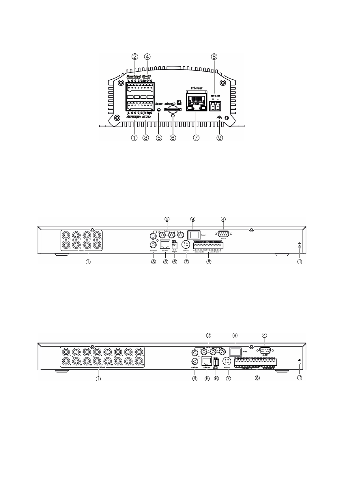
Figure 2: Back panel
1-channel and 4-channel:
1. Alarm In
2. Alarm Out / Audio In, RCA connector
3. RS-232 serial interface
4. RS-485 serial interface
5. Reset button
6. Micro SD card slot
7. LAN network interface
8. 12 VDC power input
9. GND
8-channel:
1. Video In
2. Audio In, RCA connector
3. Audio Out, RCA connector
4. RS-232 serial interface
5. LAN network interface
16-channel:
6. RS-485 serial interface
7. 12 VDC power input
8. Alarm In/Out
9. Power switch
10. GND
1. Video In
2. Audio In, RCA connector
3. Audio Out, RCA connector
4. RS-232 serial interface
5. LAN network interface
6 TVE-120-420-820-1620 Encoder User Manual
6. RS-485 serial interface
7. 12 VDC power input
8. Alarm In/Out
9. Power switch
10. GND
Page 11
1
2
3
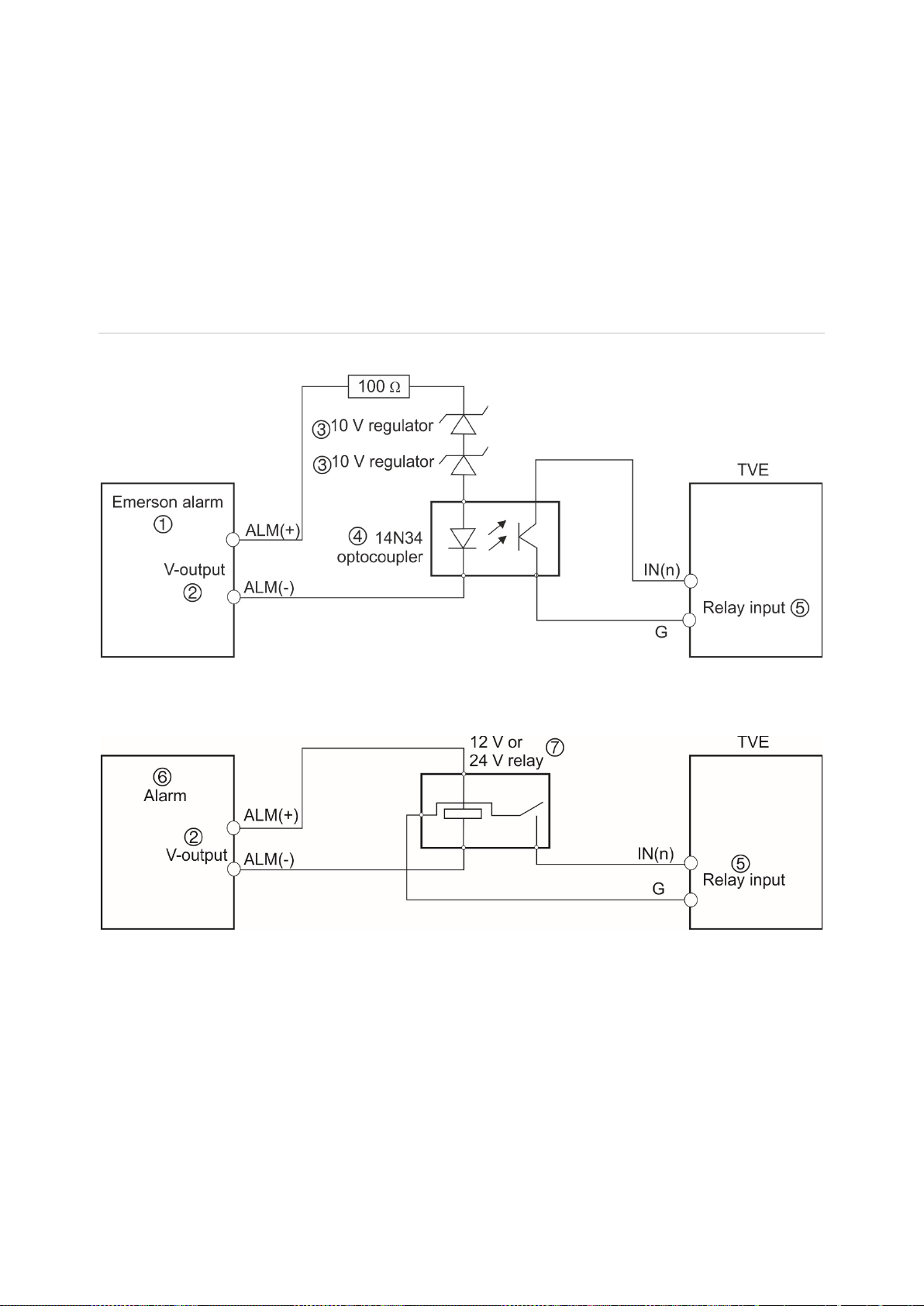
7. 12 V or 24 V relay
Connections
See Figure 2 on page 6 for information on connecting the power, camera, audio, and
network cables.
Alarm connections
The TVE encoder supports the open/close relay input as the alarm input mode. When
the alarm input signal not in open/close relay signal mode, please follow the
connections shown below.
Figure 3: Alarm input connections
Alarm input connections for Emerson alarm:
Alarm input connections for normal alarm:
. Emerson alarm
. V output
. 10 V regulator
4. 4N35 optocoupler
5. Relay output
6. Normal alarm
The alarm input can be selected to NO or NC. Different alarm output connection
methods are applied to the AC or DC load. See Figure 3.
TVE-120-420-820-1620 Encoder User Manual 7
Page 12
Getting started
All encoder configuration and control is done via the webpage. Before you start using
the encoder, you must first activate the device by setting up a strong password.
Default network settings
The default network settings are:
• IP address - 192.168.1.70
• Subnet mask - 255.255.255.0
• Gateway address - 192.168.1.1
• HTTP port: 80
• Server: 8000
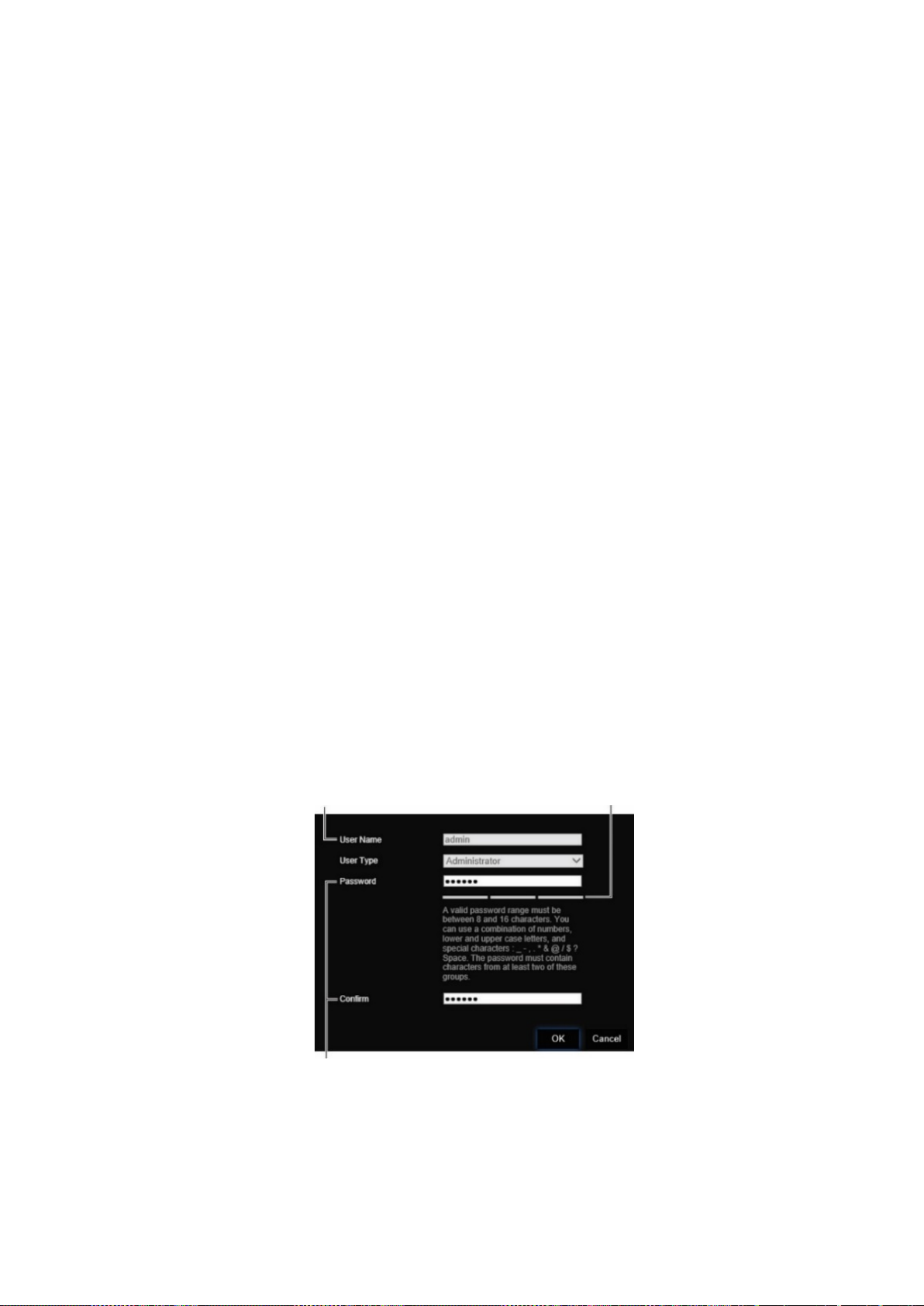
When you f irst start up the device, the Activation window appears. You must define a
high security admin password before you can access the device. There is no default
password provided.
Tips on creating a strong password:
• A valid password range must be between 8 and 16 characters. You can use a
combination of numbers, lower and upper case letters, and special characters: _ - , *
& @ / $ ? Space. The password must contain characters from at least two of these
groups.
• The password is case-sensitive so use a mixture of upper and lower case letters.
• Do not use personal information or common words as a password
User Name: It is always “admin”. It cannot
be changed. The bar showing password strength
Enter the new admin password and confirm it.
8 TVE-120-420-820-1620 Encoder User Manual
Page 13

Accessing the web browser
The browser menus are available in English and 10 other languages.
To access the web browser: (Internet Explorer only)
1. Open the web browser and select your language.
2. Enter the IP address of the encoder (for example, http://192.168.1.70). Press the
Enter key on the computer. The system displays the login window.
3. Enter the user name (default: admin) and password to log into the system. The
encoder’s main page appears, which by default is Live View (see page 11).
Device manager network settings
Use TruVision Device M anag er to find and configure the IP address and other
parameters of the device. This tool automatically identifies TruVision devices that
support “auto-discovery” anywhere on the network, even in different subnets.
To use the TruVision Device Manager:
1. Download the tool from our website.
2. Double-click the shortcut icon to open the tool. Click Device Manager to begin the
discovery process. The list of TruVision devices located on your network appears.
Note: The TruVision Device Manager can only detect devices that are on the same
LAN. The tool cannot detect devices placed on a VLAN.
3. Change the device settings as required. Click X on the top right corner when
completed.
TVE-120-420-820-1620 Encoder User Manual 9
Page 14
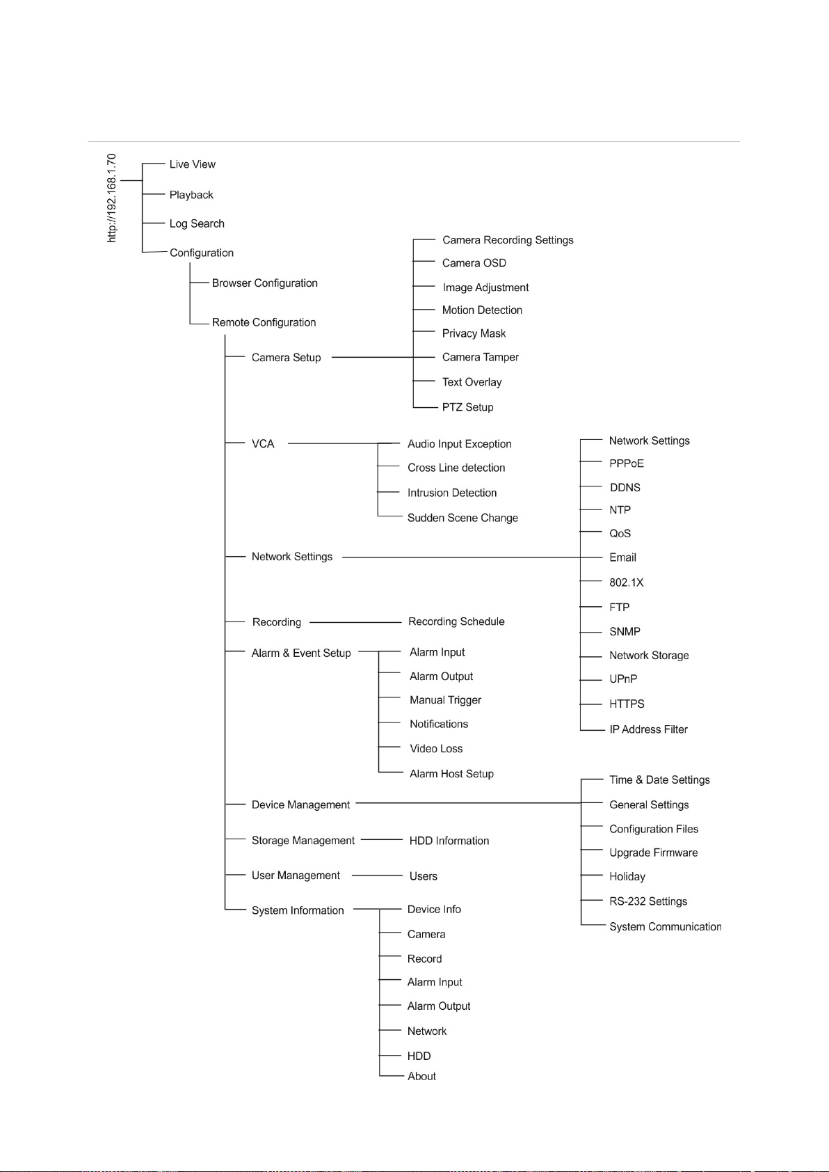
Menu tree
Figure 4: Encoder menu tree
10 TVE-120-420-820-1620 Encoder User Manual
Page 15
Protocol
Stream Type
Multiscreen Display
Video File Size
Latency
Auto
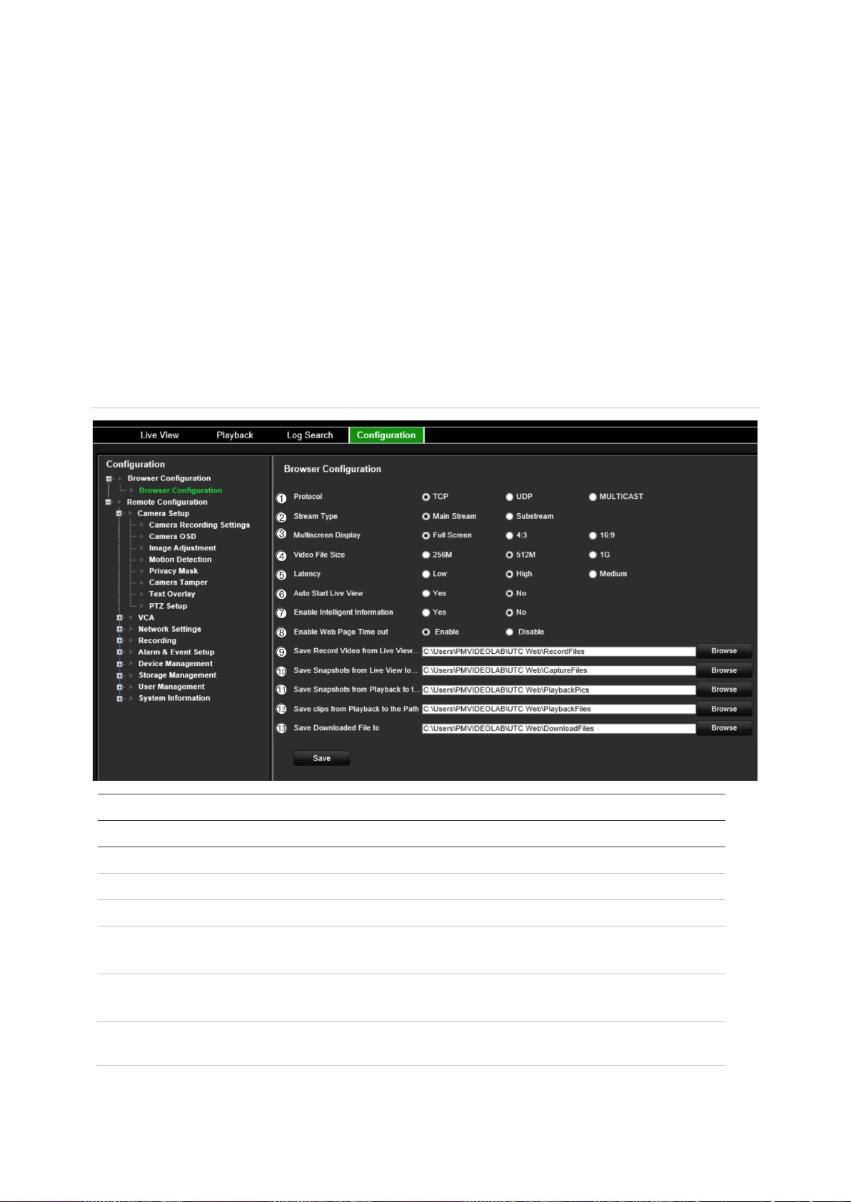
Browser configuration
There are two main configuration menus in the in the menu toolbar:
Browser Configuration
Remote Configuration
Use the Browser Configuration menu to manage the protocol type, live view
performance and local storage paths. In the Configuration panel, click Browser
Configuration to display the browser configuration window. See Figure 5 below for
descriptions of the diff er ent me nu par a met ers.
Use the Remote Configuration menu to configure the camera, VCA, network settings,
recording, alarm and events setup, device management, user management, and to see
system information. These functions are described in the subsequent chapters.
Figure 5: Browser configuration window
Parameters Description
Live View Parameters
1.
2.
3.
4.
5.
6.
TVE-120-420-820-1620 Encoder User Manual 11
Specify the network protocol used: TCP, UDP or MULTICAST.
Select the type of stream: Mainstream or Substream.
Select the monitor display: Full screen, 4:3, or 16:9.
Specify the maximum file size.
Options include: 256 MB, 512 MB and 1G.
Specify the transmission speed.
Options include: Shortest Delay, Auto or Fluent.
Start Live View If enabled, automatically start all the live views when the users
navigate to Live View tab.
Page 16

Enable Intelligent
Information
Enable Web Page Time
Out
mouse has not been moved for more than 5 minutes, no matter
Save
Live View
Save
View
Save
Playback
Save Clips from Playback
to
Save
Parameters Description
7.
8.
File Saved Location Settings
9.
Record Videos from
to the Path
10.
Snapshots From Live
to the Path
11.
Snapshots from
to the Path
12.
the Path
13.
Downloaded Files to Specify the directory for downloaded files.
If enabled, display the rules for VCA features such as lines and
areas, in live view.
If enabled, the web page will time out after 5 minutes if the
whether user is in li ve vie w or playbac k.
Specify the directory for recorded files.
Specify the directory for saving sna pshots in live v ie w m ode.
Specify the directory for saving snapshots in playback mode.
Specify the directory for saving video c lips in pl a yback m ode.
12 TVE-120-420-820-1620 Encoder User Manual
Page 17
1
2
3
4
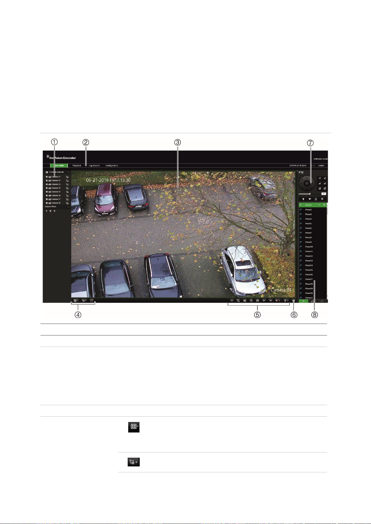
Live view
Live view mode is the normal operating mode of the device where you watch live
images from the cameras. The encoder automatically enters into live mode once
powered up. On the viewer, you can see the current date and time, as well as the
camera name.
Description of live view
Figure 6: Live view
Name Description
. Device list Display the encoder and its channels.
. Menu toolbar Lets you do the following:
• View live video
• Play back video
• Search for event logs
• Configure settings
• Exit the interface
. Viewer View live video.
. Display format
Define how you want video to be displayed in the viewer; single
screen, 2X2, 3X3 or 4X4.
When in multiview mode, double-click a video tile to get fullscreen mode. Double-click again to return to multiview mode.
Switch between main stream and substream.
TVE-120-420-820-1620 Encoder User Manual 13
Page 18
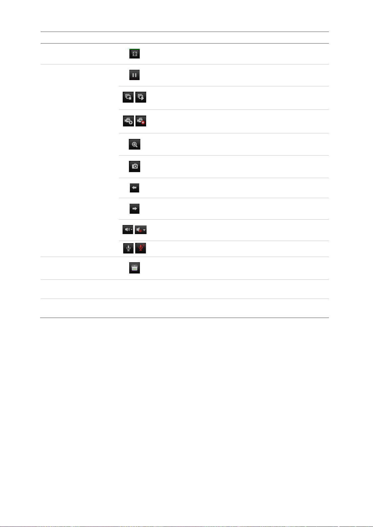
5
6
7
8
Name Description
Click to switch to full screen mode.
. Video function
toolbar
/
/
/
/
Pause
Click to start/stop all viewing.
Click to manually start/stop recording video. The recording is
saved on the computer.
Enable e-PTZ (must be supported by the connected camera).
Click to capture a snapshot of a video image. The image is
saved on the computer.
Click to display the previous camera view.
Click to display the next camera view.
Click to turn audio on/off.
Start/Stop bi-directional audio.
. Alarm Trigger Output
. PTZ control panel Control PTZ of the currently selected camera, adjust the speed of PTZ
movement and turn on/off the camera light and wiper.
. Preset setup /
selection
Set up and select presets.
Turn Alarm Output on/off.
To see live view:
1. Open the encoder’s web browser screen. See Figure 6.
2. Double-click a camera from the device list to select a camera to view.
3. Click the Display Format button to view multiple video tiles.
Capture a snapshot
In live view mode, click the snapshot button on the video function toolbar to capture live
pictures. A pop-up message will appear on screen to confirm that the capture was
successful. The image is saved as a JPEG file on the computer.
Note: Configure where the snapshots are saved on your computer in the Configuration
> Browser Configuration menu on page 11.
14 TVE-120-420-820-1620 Encoder User Manual
Page 19
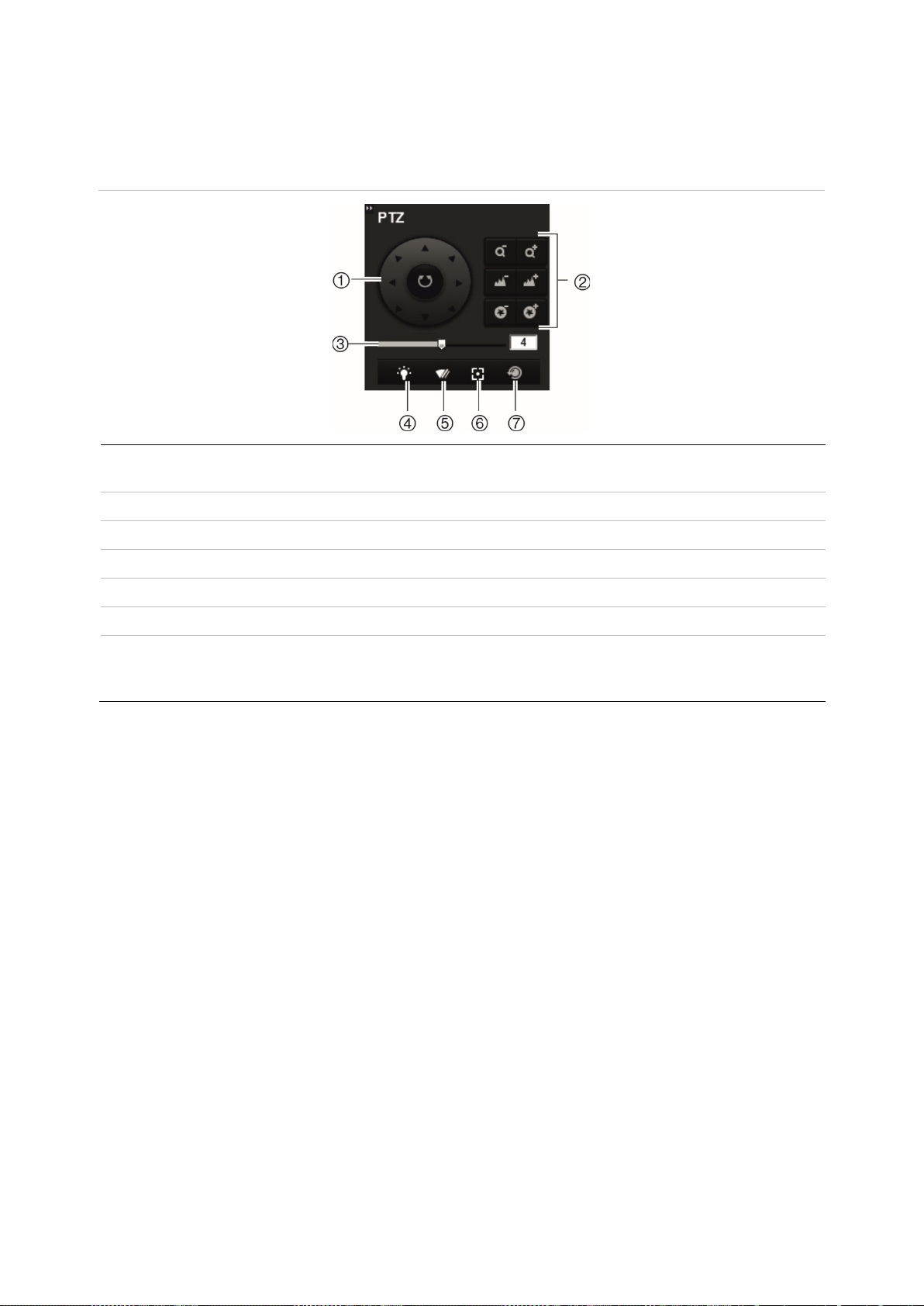
PTZ control
You can control PTZ cameras from the encoder in live view mode.
Figure 7: PTZ control
1. Directional pad/auto-scan
buttons
2. Zoom, focus, and iris Adjusts zoom, focus and iris.
3. PTZ movement Adjust the speed of the pan and tilt movement.
4. Camera light Turns on/off camera light (when available).
5. Camera wiper Turns on/off camera wiper (when avai lab le).
6. Auxiliary focus Automatically focus the camera lens for the sharpest picture.
7. Lens initialization Initialize the lens of a camera with a motorized lens, such as PTZ
Controls the movements and directions of the PTZ. The center
button is used to start auto-pan by the PTZ dome camera.
or IP cameras. This function helps to maintain lens focus accuracy
over prolong periods of time.
Connecting the PTZ camera to the encoder
Ensure that the PTZ dome cameras are correctly connected to the RS-485 port on the
encoder back panel. Connect the R- and R+ terminals of the PTZ camera or PTZ
dome to the RS-485 T- and RS-485 T+ terminals respectively.
Configure the RS-485 parameters in the Configuration > Remote Configuration >
Serial Port Settings > 485 Serial Port menu.
Presets
Presets are previously defined locations of a PTZ dome camera. They allow you to
quickly move the PTZ dome camera to a desired position. Up to 256 presets can be
configured.
To set up a preset:
1. In live view mode, select a preset from the preset list.
TVE-120-420-820-1620 Encoder User Manual 15
Page 20
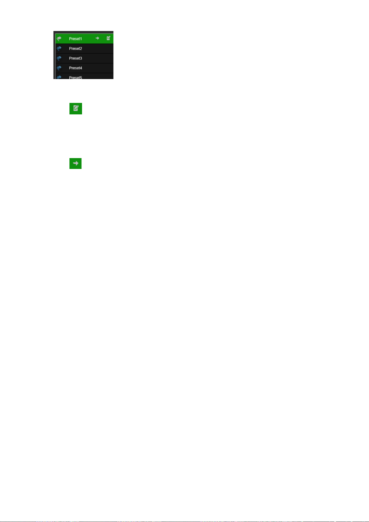
2. Use the directional, zoom, focus and iris buttons to position the camera in the
desired preset locatio n .
3. Click to save the position.
To call up a preset:
1. In live view mode, select a camera.
2. Select a preset from the preset list.
3. Click . The camera immediately moves to that preset position.
16 TVE-120-420-820-1620 Encoder User Manual
Page 21
Name
1
2
3
4
5
6
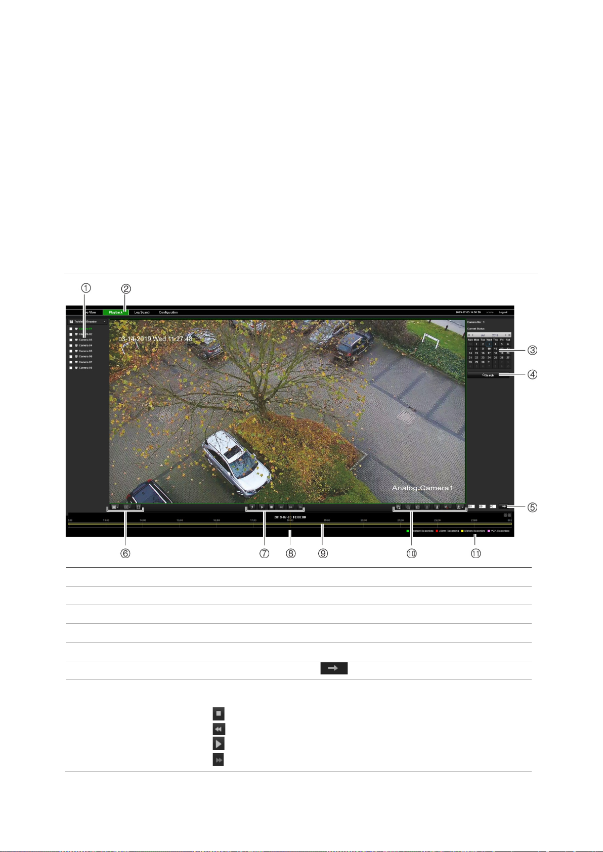
Playback
This feature is availabl e for the one- and four-channel encoders with SD card as well as
encoders with NAS storage set up.
You can easily search and play back recorded video in the playback interface.
Note: You must insert an SD card in the encoder (1 and 4-ch encoders only) or use a
NAS to be able to use the playback functions .
To search recorded video stored on the camera’s storage device for playback, click
Playback on the menu toolbar. The Playback window displays. See Figure 8 below.
Note: You must have playback permission to play back recorded images. See “User
management” on page 66 for more information.
Figure 8: Playback window
Description
. Cameras Available cameras.
. Playback button Click to open the Playback window.
. Search calendar Click the day required to search.
. Search Start search.
. Set playback time Input the time and click to locate the playback point.
. Control playback Click to control how the selected file is played back: play, stop, slow
and fast forward playback.
Stop
Speed down
Play
Speed up
TVE-120-420-820-1620 Encoder User Manual 17
Page 22

Name
Playback by frame
7
8
9
10
11
12
Download video files.
13
Description
. Archive functions Click these buttons for the following archive actions:
Capture and download a snapshot image of the playback video.
Start/Stop clipping video files.
. Digital zoom Click to enable digital zoom.
. Audio control Control level of audio. Drag to adjust the volume.
. Time moment Vertical bar shows where you are in the playback recording. The
current time and date are also displayed.
. Timeline bar The timeline bar displays the 24-hour period of the day being played
back. It moves left (oldest) to right (newest). The bar is color-coded to
display the type of recording.
Click a location on the timeline to move the cursor to where you want
playback to start. The timeline can also be scrolled to earlier or later
periods for play back.
Click to zoom out/in the timeline bar.
. Download functions
. Recording type The color code displays the recording type. Recording types are
Continuous recording (blue), Alarm recording (red), and manual
recording (yellow).
The recording type name is also displayed in the current status
window.
To play back recordings:
1. Click Playback on the menu bar to enter the playback interface.
2. Select the date in the calendar and click Search.
3. Click to play the video files found on this date.
Use the toolbar on the bottom of playback interface to control the playing process.
See Figure 8 above for information on what the icons mean.
Note: You can choose the file paths locally for downloaded playback video files and
snapshots under Local Configuration.
To play back from a specific time, enter the time and click to locate the
playback point.
4. Click a location on the timeline to move the cursor to where you want playback to
start. The timeline can also be scrolled to earlier or later periods for play back. Click
to zoom out/in of the timeline bar.
5. To download video files, click .
18 TVE-120-420-820-1620 Encoder User Manual
Page 23
Camera configuration
Use the Camera Setup menu under Remote Configuration to configure analog
cameras. You can also configure the camera OSD, recording settings, image quality,
motion detection, privacy masking, camera tampering, text overlay, and PTZ
configuration.
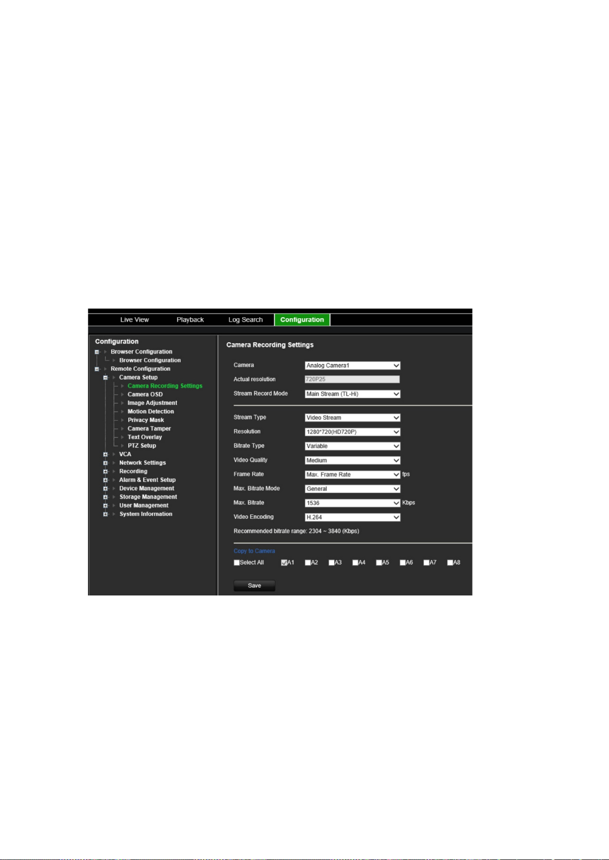
Camera recording settings
You can adjust the video streaming parameters to obtain the image quality and file size
best suited to your needs.
To configure video settings:
1. From the menu toolbar, click Configuration and then Remote Configuration >
Camera Setup > Camera Recording Settings. The Camera Recording Settings
window appears.
2. Select a camera from the drop-down list.
3. Select the Stream Record Mode of the camera: Main Stream (TL-Hi), Main Stream
(TL-Lo), Main Stream (Event), Main Stream (Alarm), or Substream.
The main stream is usually for recording and live viewing with good bandwidth, and
the substream can be used for live viewing when the bandwidth is low. Refer to
“Browser configuration” on page 11 on how to change main strea m t o subs tr ea m for
live viewing.
4. You can customize the following parameters for the selected Main Stream or
Substream:
TVE-120-420-820-1620 Encoder User Manual 19
Page 24

Stream Type: Select the video type to video stream, or video & audio composite
stream. The audio signal will be recorded only when the video type is Video &
Audio.
Resolution: Select the resolution of the video input.
Bitrate Type: Select the bitrate type to constant or variable. When Variable is
selected, six levels of video quality can be configured.
Video Quality: Select the video quality level. Default is Medium.
Frame Rate: Select the recording frame rate.
The frame rate used to describe the frequency at which a video stream is updated is
measured in frames per second (fps). A higher frame rate is advantageous when
there is movement in the video stream, as it maintains image quality throughout.
Max. Bitrate Mode: Select the general (Default) or customized option.
Max. Bitrate: Set the maximum bitrate between 32 and 8192 Kbps .
Video Encoding: Select the video encoding standard to H.264 or H.265.
6. If you want to copy the display settings of the current camera to other cameras, go
to the Copy to Camera panel and select the camera(s) to copy, or click Select All
to select all cameras.
7. Click Save to save the settings.
Camera OSD
You can configure which information is displayed on-screen. The on-screen display
(OSD) settings appear in live view and recording modes and include the camera name,
time and date. You can also adjust the transparency of the OSD relative to the
background so that it is easier to read or is less prominent on screen.
To configure the OSD settings:
1. From the menu toolbar, click Configuration and then Remote Configuration >
Camera Setup > Camera OSD. The Camera OSD window appears.
20 TVE-120-420-820-1620 Encoder User Manual
Page 25
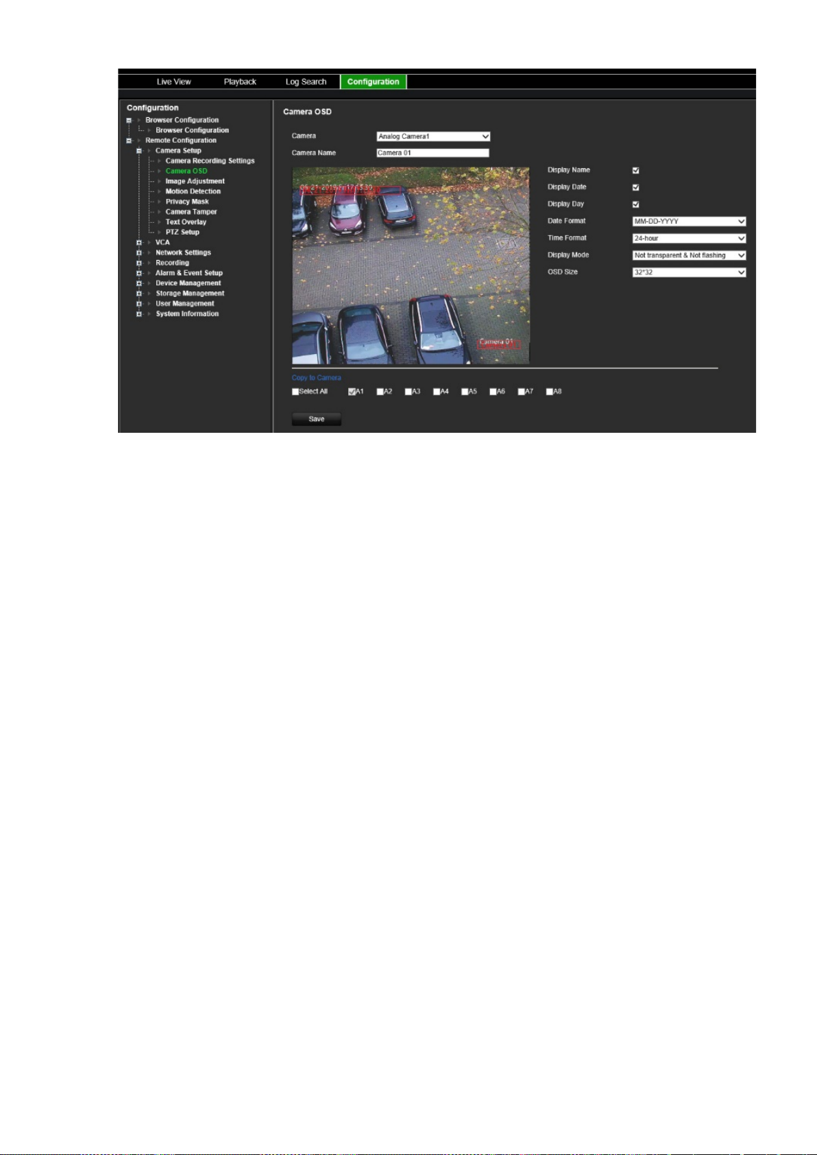
2. Select a camera from the drop-down list.
3. Edit the camera name in Camera Name.
4. Select to display the camera name as well as the date and/or day.
5. Select the date format, time format, and OSD display mode. The default OSD
display mode is Not Transparent & Not Flashing.
6. On the live image, you can adjust the OSD text location on screen by moving the
red text frames.
7. If you want to copy the display settings of the current camera to other cameras, go
to the Copy to Camera panel and select the camera(s) to copy, or click Select All
to select all cameras.
8. Click Save to save the settings.
Image adjustment
You can manually adjust the brightness, contrast, saturation, hue, sharpness and digital
noise reduction values of the camera image to get the best image quality.
To configure the image settings:
1. From the menu toolbar, click Configuration and then Remote Configuration >
Camera Setup > Image Adjustment. The Image Adjustm ent window appears.
2. Select a camera from the drop-down list.
TVE-120-420-820-1620 Encoder User Manual 21
Page 26

3. Select the type of scene: Standard, Indoor, Outdoor, or Dim Light.
4. Move the slider to adjust the brightness, contrast, saturation, hue, sharpness, and
digital noise reduction.
5. Click Save to save the settings.
Motion detection
The encoder can be set up to trigger an alarm if it detects motion, which can then be
recorded, for example on a network storage device. You can then search these
recorded motion activities for specific incidents.
Select the level of sensitivity to motion so that only objects that could be of interest can
trigger a motion recording. For example, recording is triggered by the movement of a
person but not that of a cat.
To configure motion detection:
1. From the menu toolbar, click Configuration and then Remote Configuration >
Camera Setup > Motion Detection. The Motion Detection window appears.
22 TVE-120-420-820-1620 Encoder User Manual
Page 27

2. Select a camera from the drop-down list. Each camera must be set up individually.
3. Select Enable Motion Detection.
4. Select the Enable Dynamic Analysis check box. When enabled, the motion
detection triggered frame (green) of the moving targets in the motion detection area
will be displayed on the live video.
5. Select the area sensitive to motion and its sensitivity level.
Select the Area Settings tab. Click Start Draw. Click and drag the mouse cursor
across the screen. The area selected appears as a red grid. Areas covered by the
red grid are sensitive to motion detection. Up to eight areas can be dr awn. Click
Stop Draw when completed. Click Erase to deselect an area. Click Clear to clear
the screen.
Drag the Sensitivity scroll bar to the desired sensitivity level.
Click Save to save the settings.
6. If you want to copy the motion detection settings of the current camera to other
cameras, under Copy to Camera select the camera(s) to copy, or click Select All to
select all cameras.
7. Select the recor di ng schedules for motion detection.
Click the Arming schedule tab.
TVE-120-420-820-1620 Encoder User Manual 23
Page 28

Enter the start time (hour and
minutes)
Enter the end time (hour and minutes)
Click the timeline of the desired day. A pop-up appears that lets you enter the start
and end times of the arming schedule for that day. Alternatively, you can also
manually modify the length of the green timeline to the desired times.
Click to copy the schedule to other days or to the whole week.
You can schedule only one time period in a day. Default is 24 hours. Note that when
motion detection is enabled, motion events will always trigger event recording,
regardless of the arming schedule.
8. Select the response method to motion detection.
Click the Actions tab.
24 TVE-120-420-820-1620 Encoder User Manual
Page 29

Under Alarm Linking, check one of more of the desired res ponse methods:
- Enable Alarm Audio: Enable the buzzer.
- Notify Alarm Host: Send a notification or alarm signal to remote alarm host
when an event occurs. The alarm host refers to the computer installed with
remote client software
- Send Email: Send an email with alarm information to a user or users when an
event occurs.
- Upload Snapshot to FTP: Capture the image when an alarm is triggered and
upload the picture to a FTP server.
Under Trigger Alarm Output select one of more alarm outputs to trigger an
external alarm when a motion detection event occurs. See “Alarm output settings”
on page 51 on how to set up an external alarm output.
Under Trigger Channel, select one or more channels to trigger recording when a
motion detection event occurs.
9. If you want to copy the motion detection settings of the current camera to other
cameras, under Copy to Camera select the camera(s) to copy, or click Select All to
select all cameras.
10. Click Save to save settings.
Privacy masking
You can define an area on screen to remain hidden from view. For example, you can
choose to block the view of a camera when overlooking residential premises. This
hidden area is referred to as privacy masking. Privacy masking cannot be viewed in live
view or recorded mode, and appears as a blank area on the video image.
TVE-120-420-820-1620 Encoder User Manual 25
Page 30

To configure a privacy mask:
1. From the menu toolbar, click Configuration and then Configuration > Remote
Configuration > Camera Setup > Privacy Mask. The Privacy Mask window
appears.
2. Select a camera from the drop-down list. Each camera must be set up individually.
3. Select the Enable Privacy Mask check box.
4. Click the Draw Area button to start drawing a block on an area.
5. Using the mouse, click and drag a privacy-mask box in the camera view screen over
the desired area. You can set up to four areas for privacy masking.
6. Click Stop Draw when completed. Click Clear to clear the screen.
7. If you want to copy the privacy mask settings of the current camera to other
cameras, under Copy to Camera select the camera(s) to copy, or click Select All to
select all cameras.
8. Click Save to save the settings.
Camera tamper
Video tampering, such as moving a camera to a different position, can also be detected
and set to trigger an action on the enco der .
Note: It is strongly recommended not to configure for video tampering when using PTZ
dome cameras.
To configure tamper-proof detection:
1. From the menu toolbar, click Configuration and then Remote Configuration >
Camera Setup > Camera Tamper. The Camera Tamper window appears.
26 TVE-120-420-820-1620 Encoder User Manual
Page 31

2. Select a camera from the drop-down list. Each camera must be set up individually.
3. Select the Enable Camera Tamper check box.
4. Under the Area Settings tab, the whole screen is set for tamper-proof detection by
default. This cannot be chang ed . Drag the Sensitivity scroll bar to the desired
sensitivity level.
5. Select the Arming Schedule tab to modify the arming schedule for video loss
detection. The configuration is the same as that for motion detection (see “Motion
detection” on page 22).
You can schedule only one time period in a day. Default is 24 hours.
6. Click the Actions tab.
TVE-120-420-820-1620 Encoder User Manual 27
Page 32

Under Alarm Linking, check one of more of the desir ed res ponse method:
- Enable Alarm Audio: Enable the buzzer.
- Notify Alarm Host: Send a notification or alarm signal to remote alarm host
when an event occurs. The alarm host refers to the computer installed with
remote client software
- Send Email: Send an email with alarm information to a user or users when an
event occurs.
Under Trigger Alarm Output select one of more alarm outputs to trigger an
external alarm when a motion detection event occurs. See “Alarm output settings”
on page 51 on how to set up an external alarm output.
7. If you want to copy the tamper settings of the current camera to other cameras,
under Copy to Camera select the camera(s) to copy, or click Select All to select all
cameras.
8. Click Save to save the settings.
Text overlay
You can add up to eight lines of text on screen. This option can be used, for example,
to display emergency contact details.
To add a text overlay:
1. From the menu toolbar, click Configuration and then Remote Configuration >
Camera Setup > Text Overlay. The Text Overlay window appears.
2. Select a camera from the drop-down list.
3. Enter the user-defined text content. Up to six character strings can be edited.
28 TVE-120-420-820-1620 Encoder User Manual
Page 33

Select the check box alongside a text box for the text to be displayed on screen.
4. In the preview image you can adjust the text location on screen by moving the red
text fram e.
5. If you want to copy the text overlay settings of the current camera to other cameras,
under Copy to Camera select the camera(s) to copy, or click Select All to select all
cameras.
6. Click Save to save the settings.
PTZ setup
Use the PTZ Setup menu to configure analog PTZ dome cameras. Each camera must
be set up individually. The cameras must be configured before they can be used.
HD-TVI PTZ cameras can be controlled over the coax cable.
Ensure that the PTZ dome cameras are correctly connected to the RS-485 port on the
back panel.
Note: If a camera does not work correctly after configuring the encoder, confirm the
parameters entered.
To configure PTZ dome camera settings:
1. Click the PTZ Control icon on the live view toolbar.
— or —
Click Configuration > Remote Configuration > Camera Setup > PTZ Setup. The
PTZ Setup window appears.
2. Select the camera, baud rate, data bit, stop bit, parity, flow control, PTZ protocol and
PTZ address for the camera.
TVE-120-420-820-1620 Encoder User Manual 29
Page 34

Note: It is important to ensure that the settings correspond with those used in the
PTZ camera.
3. If you want to copy the PTZ settings of the current camera to other cameras, under
Copy to Camera select the camera(s) to copy, or click Select All to select al l
cameras.
4. Click Save to save the settings.
30 TVE-120-420-820-1620 Encoder User Manual
Page 35

VCA settings
The configuration of each individual VCA (Video Content Analysis) event is done in the
camera browser. Within the encoder, you are able to li nk acti ons to a VCA alarm from
IP cameras that support this feature.
The encoder can be set up to detect several types of VCA events, which can then
trigger a series of linkage methods:
• Audio Input Exception
• Cross Line Detection
• Intrusion Detection
• Sudden Scene Change
Audio input exception
Audio exception detection detects sounds that are above a selected threshold.
You can set it to detect a sudden rise and/or fall in sound intensity. The smaller the
sensitivity level set, the larger the change in sound needs to be to trigger detection. The
sound intensity threshold filters the sound in the environment. The louder the
environmental sound, the higher the value.
To setup audio input exception actions:
1. From the menu toolbar, click Configuration and then Remote Configuration >
VCA > Audio Input Exceptions. The Audio Input Exceptio ns window appears.
2. Select a camera from the drop-down list.
3. Select the type of audio input exception.
Click the Exception Detection tab. Select the type of audio input exception to be
detected: Audio Loss Detec ti o n, Sudden Increase of Sound Inte nsi t y, or Sudden
Decrease of Sound Intensity.
TVE-120-420-820-1620 Encoder User Manual 31
Page 36

Drag the Sensitivity scroll bar to the desired sensitivity level for Sudden Increase of
Sound Intensity and Sudden Decrease of Sound Intensity.
Drag the Sound Intensity Threshold scroll bar to the desired sensitivity level for
Sudden Increase of Sound Intensity.
4. Select the arming schedules for the VCA event.
Click the Arming Schedule tab. Select the day of the week and the time periods
during the day when audio can be detected. The configuration is the same as that
for motion detection (see “Motion detection” on page 22). You can schedule only
one time period in a day. Default is 24 hours.
5. Select the response method to the VCA event.
6. Click the Actions tab. Under Alarm Linking, check one of more of the desi r ed
response method:
- Enable Alarm Audio: Enable the buzzer.
- Notify Alarm Host: Send a notification or alarm signal to remote alarm host
when an event occurs. The alarm host refers to the computer installed with
remote client software
- Send Email: Send an email with alarm information to a user or users when an
event occurs.
Under Trigger Alarm Output select one of more alarm outputs to trigger an
external alarm when a motion detection event occurs. See “Alarm output settings”
on page 51 on how to set up an external alarm output.
Under Trigger Channel, select one or more channels to trigger recording when a
motion detection event occurs.
Select the PTZ control acti ons to li nk to t he V C A event. Under PTZ Linking, select
the PTZ camera and enter the preset, preset tour, and/or a shadow tour to be
triggered when the alarm is detected. Select Enable to activate the option.
7. Click Save to save all the settings.
Cross line detection
This function can be used to detect people, vehicles and objects crossing a pre-defined
line or an area on-screen. The line crossing direction can be set as unidirectional or
bidirectional. Unidirectional is crossing the line from left to right or from right to left.
Bidirectional is crossing the line from both directions.
To setup cross line detection actions:
1. From the menu toolbar, click Configuration and then Remote Configuration >
VCA > Cross Line Detection. The Cross Line Detection window appears.
2. Select a camera from the drop-down list.
3. Enable Cross Line Detection.
4. Select the area where you want detection to start.
32 TVE-120-420-820-1620 Encoder User Manual
Page 37

Click the Area Settings tab. Click Start Draw. A vertical line appears in the middle
of the image, which is bidirectional by default. You can move the line anywhere on
screen and change its angle. Up to four lines can be set, each with a different rule.
Click Clear to clear the line.
Set up a rule to be associated with this line. Under Line, select a line number from
the drop-down list. Under Direction, select the direction rule:
A<->B: Only the arrow on the B side is displayed. When an object moves across
the plane in both directions, it is detected and alarms are tri g g er ed.
A->B: Only an object crossing the pre-defined line from the A to the B side can be
detected and trigger an alarm.
B->A: Only an object crossing the pre-defined line from the B to the A side can be
detected and trigger an alarm.
Set the sensitivity level between 1 and 50.
To draw a new line, if required, select another line number from the drop-down list
and then draw the line and set its direction rule values. Each line will be
automatically numbered.
5. Select the arming schedules for the VCA event.
TVE-120-420-820-1620 Encoder User Manual 33
Page 38

Click the Arming Schedule tab. Select the day of the week and the time periods
during the day when cross line can be detected. The configuration is the same as
that for motion detection (see “Motion detection” on page 22). You can schedule
only one time period in a day. Default is 24 hours. Click Save to save the settings.
Click Copy to copy these settings to other days of the week.
6. Select the response method to the VCA event.
Click the Actions tab. Under Alarm Linking, check one of more of the desired
response method:
- Enable Alarm Audio: Enable the buzzer.
- Notify Alarm Host: Send a notification or alarm signal to remote alarm host
when an event occurs. The alarm host refers to the computer installed with
remote client software
- Send Email: Send an email with alarm information to a user or users when an
event occurs.
Under Trigger Alarm Output select one of more alarm outputs to trigger an
external alarm when a motion detection event occurs. See “Alarm output settings”
on page 51 on how to set up an external alarm output.
Under Trigger Channel, select one or more channels to trigger recording when a
motion detection event occurs.
Select the PTZ control actions to link to the VCA event. Under PTZ Linking, select
the PTZ camera and enter the preset, preset tour, and/or a shadow tour to be
triggered when the alarm is detected. Select Enable to activate the option.
7. Click Save to save all the settings.
Intrusion detecti on
You can set up an area in the surveillance scene to detect when intrusion occurs. If
someone enters the area, a set of alarm actions can be triggered.
To setup intrusion detection actions:
1. From the menu toolbar, click Configuration and then Remote Configuration >
VCA > Sudden Scene Change. The Sudden Scene Change window appears.
2. Select a camera from the drop-down list.
3. Select Enable Intrusion Detection.
4. Select the area where you want intrusion detec ti on to st art .
Click the Area Settings tab. Select the region number to be drawn. Click Start
Draw and click on the camera image where you want the detection area to start.
When you draw the rectangle, all lines should connect end-to-end to each other. Up
to four regions are supported, each with a different time threshold and sensitivity.
Click Clear to clear the rectangles.
Note: The area can only be quadrilateral.
34 TVE-120-420-820-1620 Encoder User Manual
Page 39

Select the time threshold, sensitivity levels and percentage of the region.
The time threshold is the time that the object remains in the region. If you set the
value as 0 s, the alarm is triggered immediately after the object enters the region.
The range is between 0 and 2.
The sensitivity value defines the size of the object that can trigger the alarm. When
the sensitivity is high, a small object can trigger an alarm. The range is between 1
and 100.
To draw a new rectangle, if required, select another region number fr om the dr opdown list and then draw the region and set its threshold and sensitivity values.
5. Select the arming schedules for the VCA event.
Click the Arming Schedule tab. Select the day of the week and the time periods
during the day when intrusion can be detected. The configuration is the same as
that for motion detection (see “Motion detection” on page 22). You can schedule
only one time period in a day. Default is 24 hours. Click Save to save the settings.
Click Copy to copy these settings to other days of the week.
Click Save to save the settings. Click Copy to copy these settings to other days of
the week.
6. Select the response method to the VCA event.
Click the Actions tab. Under Alarm Linking, check one of more of the desired
response method:
TVE-120-420-820-1620 Encoder User Manual 35
Page 40

- Enable Alarm Audio: Record audio with the video.
- Notify Alarm Host: Send a notification or alarm signal to remote alarm host
when an event occurs. The alarm host refers to the computer installed with
remote client software
- Send Email: Send an email with alarm information to a user or users when an
event occurs.
Under Trigger Alarm Output select one of more alarm outputs to trigger an
external alarm when a motion detection event occurs. See “Alarm output settings”
on page 51 on how to set up an external alarm output.
Under Trigger Channel, select one or more channels to trigger recording when a
motion detection event occurs.
Select the PTZ control actions to link to the VCA event. Under PTZ Linking, select
the PTZ camera and enter the preset, preset tour, and/or a shadow tour to be
triggered when the alarm is detected. Select Enable to activate the option.
7. Click Save to save all the settings.
Sudden scene change
You can configure the camera to trigger an alarm when the camera detects a change in
the scene caused by a physical repositioning of the camera.
To setup sudden scene change actions:
1. From the menu toolbar, click Configuration and then Remote Configuration >
VCA > Sudden Scene Change. The Sudden Scene Change window appears.
2. Select a camera from the drop-down list.
36 TVE-120-420-820-1620 Encoder User Manual
Page 41

3. Select Enable Sudden Scene Change.
4. Select the sensitivity of the change.
5. Select the arming schedules for the VCA event.
Click the Arming Schedule tab. Select the day of the week and the time periods
during the day when the sudden scene change can be detected. The configuration
is the same as that for motion detection (see “Motion detection” on page 22). You
can schedule only one time period in a day. Default is 24 hours. Click Save to save
the settings. Click Copy to copy these settings to other days of the week.
Click Save to save the settings. Click Copy to copy these settings to other days of
the week.
6. Select the response method to the VCA event.
Click the Actions tab. Under Alarm Linking, check one of more of the desired
response method:
- Enable Alarm Audio: Record audio with the video.
- Notify Alarm Host: Send a notification or alarm signal to remote alarm host
when an event occurs. The alarm host refers to the computer installed with
remote client software
- Send Email: Send an email with alarm information to a user or users when an
event occurs.
Under Trigger Alarm Output select one of more alarm outputs to trigger an
external alarm when a motion detection event occurs. See “Alarm output settings”
on page 51 on how to set up an external alarm output.
Under Trigger Channel, select one or more channels to trigger recording when a
motion detection event occurs.
Select the PTZ control actions to link to the VCA event. Under PTZ Linking, select
the PTZ camera and enter the preset, preset tour, and/or a shadow tour to be
triggered when the alarm is detected. Select Enable to activate the option.
7. Click Save to save all the settings.
TVE-120-420-820-1620 Encoder User Manual 37
Page 42

NIC Type
Network settings
You must configure your encoder’s network settings before using it over the network.
Network settings
Note: As every network configuration may differ, please contact your Network
Administrator or ISP to see if your encoder requires specific IP addresses or port
numbers.
To configure general network settings:
1. From the menu toolbar, click Configuration and then Remote Configuration >
Network Settings > Network Settings. The Network Settings window appears.
2. Enter the required settings:
Option Description
1.
38 TVE-120-420-820-1620 Encoder User Manual
Network interface card (NIC) is a device used to connect the encoder to a
network. Select the NIC type used from the drop-down list.
Page 43

DHCP
IPv4 Address
IPv4 Subnet Mask
IPv4 Default
Gateway
IPv6 Address
IPv6 Default
Gateway
MAC Address
Displays the MAC address. The MAC address is a unique ide ntif ier of your
MTU (Bytes)
Preferred DNS
Server
Alternate DNS
Server
Enable Dynamic
Register DNS
Name
Server Port
HTTP Port
Multicast IP
RTSP Service
Port
streaming media servers. The default value is 554.
Option Description
3.
4.
5.
6.
7.
8.
DHCP (Dynamic Host Configuration Protocol) is a protocol for assigning
an IP address dynamically to a device each time it connects to a network.
Select this check box if you have a DHCP server running and want your
encoder to automatically obtain an IP address and other network settings
from that server. The DHCP server is typically available in your router.
Default value is Enabled.
Enter the IP address for the encoder. This is the LAN IP address of the
encoder.
Default value is 192.168.1.82.
Enter the subnet mask for your network so the encoder will be recognized
within the network.
Default value is 255.255.255.0.
Enter the IP address of your network gateway so the encoder will be
recognized within the network. This is typically the IP address of your
router. Consult your router user manual or contact your ISP to get the
required information on your gateway.
Default value is 192.168.1.1.
Enter the IPv6 address for the encoder.
Default value is fe80::240:30ff:fe48:2975/64.
Enter the IPv6 address of your network gateway so the encoder will be
recognized within the network. This is typically the IP address of your
router.
9.
10.
11.
12.
13.
14.
15.
16.
17.
encoder and it cannot be changed.
Enter a value bet ween 50 0 and 967 6. Def au lt is 1500.
Enter the preferred domain name server to use with the encoder. It must
match the DNS server information of your router. Check your router’s
browser interface or contact your ISP for the information.
Enter the alternate domain name server to use with the encoder.
Select the check box to set up a dynamic IP address.
Default value is Disabled.
Enter the registered DNS name. Request the DNS name from your ISP.
Use the server port for remote client software access. The port range is
between 1024 and 65535.
Enter the server port value. The default value is 8000.
The default value is 80.
Enter a D-class IP address between 224.0.0.0 to 239.255.255.255. Only
specify this option if you are using the multicast function. Some routers
prohibit the use of multicast function in case of a network storm.
18.
The RTSP (Real Time Streaming Protocol) is a network control protocol
designed for use in entertainment and communications systems to control
TVE-120-420-820-1620 Encoder User Manual 39
Page 44

HTTPS Port
Option Description
19.
HTTPS (Hypertext Transfer Protocol Secure) is a secure protocol that
provides authenticated and encrypted communication. It ensures that
there is a secure private channel between the encoder and cameras.
The default value is 443.
3. Click Save to save the settings.
PPPoE settings
Although not usually used, you can connect the encoder directly to a DSL modem. To
do this, you need to select the PPPoE option in the network settings. Contact your ISP
to get the user name and password.
Note: The encoder will automatically reboot after enabling or disabling the PPPoE
function.
To configure PPPoE settings:
1. From the menu toolbar, click Configuration and Remote Configuration > Network
Settings > PPPoE. The PPPoE window appears.
2. Select Enable PPPoE. It is disabled by default.
3. Enter the dynamic IP address, your user name and password. Confirm the
password.
4. Click Save to save the settings.
DDNS settings
If the encoder is set up to use PPPoE as its default network connection, configure the
Dynamic DNS (DDNS) to be used in conjunction. You need to register with your ISP
before configuring your system for use with DDNS.
To set up DDNS:
1. From the menu toolbar, click Configuration and then Remote Configuration >
Network Settings > DDNS. The DDNS settings window appears.
2. Select Enable DDNS.
3. Select one of the three DDNS types listed:
• DynDNS: Enter the server address for DynDNS (i.e. members.dyndns.org). In
the DVR Domain Name field, enter the domain obtained from the DynDNS web
site. Then enter the user name and password registered in the DynDNS network.
• NO-IP server: Enter the server address for IPServer as well as the host name,
user name and password.
• ezDDNS: Enter the host name. It will automatically register it online. This is the
default option.
4. Click Save to save the settings.
40 TVE-120-420-820-1620 Encoder User Manual
Page 45

NTP settings
A Network Time Protocol (NTP) server can also be configured on your encoder to keep
the date and time current and accurate.
Note: If the device is connected to a public network, you should use a NTP server that
has a time synchronization function, such as the server at the National Time Center (IP
Address: 210.72.145.44) or europe.ntp.pool.org. If the device is s et up in a more
customized network, NTP software can be used to establish a NTP server used for time
synchronization.
To set up an NTP server:
1. From the menu toolbar, click Configuration and then Remote Configuration >
Network Settings > NTP. The NTP window appears.
2. Select Enable NTP. It is disabled by default.
3. Enter the NTP settings:
• Interval (min): Time in minutes to synchronize with the NTP server. The value
can be between 1 and 10080 minutes. Default is 60 minutes.
• NTP Server: IP address of the NTP server. Default is time.nist.gov.
• NTP Port: Port of the NTP server.
4. Click Save to save the settings.
QoS settings
Configure the QoS (Quality of Service) to help solve network delay and network
congestion by configuring the priority of data sending. The use of a QoS-aware network
can prioritize traffic and thus allow critical flows to be served before flows with lower
priority.
To set up QoS settings:
1. From the menu toolbar, click Configuration and then Remote Configuration >
Network Settings > QoS. The QoS window appears.
2. Select Enable QoS. It is disabled by default.
3. Enter the DSCP (Differentiated Services Codepoint) value for the video/audio,
event/alarm and management traffic. This value is used to mark the traffic’s IP
header. The DSCP value defines the priority level for the specified type of traffic. For
example, how much bandwidth to reserve for it.
4. Click Save to save the settings.
Email settings
The encoder can send email noti fications of alarms or notifica ti ons t h r oug h the net work.
Note: Ensure that the DNS address has bee n set up cor r ectl y beforehand.
TVE-120-420-820-1620 Encoder User Manual 41
Page 46

Option
Sender
Sender’s address
SMTP server
SMTP port
Enable SSL/TLS
Include Snapshot
Interval
Enable Server
Authentication
User Name
Password
Confirm
Receiver
Receiver’s address
To configure email settings:
1. From the menu toolbar, click Configuration and then Remote Configuration >
Network Settings > Email. The Email window appears.
2. Enter the required settings.
Description
Enter the name of the sender of the email.
Enter the sender’s email address.
Enter the SMTP server’s IP address.
Enter the SMTP port. The default TCP/IP port for SMTP is 25.
Select the check box to enable TLS and encrypt emails. If the
destination server does not support TLS, the encoder will default to
SSL.
If disabled, emails will not be encrypted and will be sent in clear text.
Select the check box if you want to send email with attached alarm
JPEG images.
The interval represents the time range in seconds between the alarm
images being sent. For example, if you set the interval at two seconds,
the second alarm image will be sent two seconds after the first alarm
image.
If your mail server requires authentication, select this check box to use
If the mail server requires authentication, enter the login user name.
If the mail server requires authentication, enter the login password.
Confirm password.
Select an email recipient. Up to three receivers can be selected.
Enter the email address of the receiver.
authentication to log in to this server and enter the login User Name
and Password.
3. Click Test to the test email settings.
Note: We recommend that you test the email settings after entering values in the
email window.
4. Click Save to save the settings.
802.1X settings
The IEEE 802.1X standard is supported by the network cameras, and when the feature
is enabled, the camera data is secured and user authentication is needed when
connecting the camera to the network protected by the IEEE 802.1X.
To use 802.1X with the encoder, the network switch needs to also to support 802.1X.
42 TVE-120-420-820-1620 Encoder User Manual
Page 47

To configure IEEE 802.1X settings:
1. From the menu toolbar, click Configuration and then Remote Configuration >
Network Settings > 802.1X. The 802.1X window appears.
2. Select Enable IEEE 802.1X. It is disabled by default.
3. Configure the 802.1X settings. Select the protocol EAP-PEAP or EAP-TLS.
EAP-PEAP:
PEAP (Protected Ex tensi bl e Authentication Protoc ol) fully encapsulates EAP and is
designed to work within a TLS (Transport Layer Security) tunnel that may be
encrypted but is authenti cat e d. Th e pri mar y motivation behind the cr eati on o f PEAP
was to help correct the deficiencies discovered within EAP since that protocol
assumes that the communications channel are protected.
- or -
EAP-TLS:
EAP-TLS (EAP Transport Layer Security) was subsequently defined by IETF RFC
5216. The protocol was created as an open standard leveraging the TLS (Transport
Layer Security) protocol and it primarily consists of the original EAP authentication
protocol.
4. Configure the remaining 802.1X settings.
Option Description
EAPOL version Version 2 is supported. Affects the format of the exchange with the RADIUS
server.
Note: The EAPOL version must be identical with that of the router or the
switch.
User Name This is a valid user name for the authentication server (usually a RADIUS
server).
Password This is a valid password for the user name specified in the previous field.
TVE-120-420-820-1620 Encoder User Manual 43
Page 48

Option Description
CA Certificate This should be obtained from the network administrator, as network policies
may differ.
User Certificate This should be obtained from the network administrator, as network policies
may differ.
Private Key This should also be requested from the network administrator.
5. Click Save to save the settings.
FTP settings
The encoder can upload snapshots of an event or alarm to an FTP server for storage.
When enabled, the system sends snapshots every two seconds to the ftp site from
each of the triggered cameras for as long as the alarm/event is active.
To configure FTP settings:
1. From the menu toolbar, click Configuration and then Remote Configuration >
Network Settings > FTP. The FTP window appears.
2. Select Enable FTP. It is disabled by default.
3. Configure the FTP settings, including FTP server address, port, user name,
password, directory, and upload type.
Directory: In the Directory Structure field, you can select the Root Directory, Parent
Directory and Child Directory. When the parent directory is selected, you have the
option to use the Device Name, Device Number or Device IP for the name of the
directory. When the Child Directory is selected, you can use the Camera Name or
Camera Number as the name of the directory.
4. Click Save to save the settings.
SNMP settings
This is an internet-standard protocol for managing devices on IP networks. Configure
this protocol to allow information on the encoder status as well as event and alarm
notifications to be sent to a surveillance center.
Before configuring this function, you must first install the SNMP software.
To configure SNMP protocol settings:
1. From the menu toolbar, click Configuration and then Remote Configuration >
Network Settings > SNMP. The SNMP window appears.
2. Select SNMP. It is disabled by default.
3. Configure the Read SNMP Community (default: public), Write SNMP Community
(default: private), Tap Address (default: empty) and Trap Port (default: 162).
4. Click Save to save the settings.
44 TVE-120-420-820-1620 Encoder User Manual
Page 49

Network storage
You can add network-attached hard drives to setup a NAS or IP SAN system.
Note: Ensure that the network storage device is available within the network and is
properly connected. Also the network storage device must be configured with NAS or IP
SAN mode.
To add network-attached hard drives:
1. From the menu toolbar, click Configuration and then Remote Configuration >
Network Settings > Network Storage. The Network Storage window appears.
2. Enter the IP address of the network storage system and file path in the text field.
Note: Under File Path, enter the file path name to define where on the remote
storage system you want to store the files. If using a NAS storage system, you must
add the prefix “/nfs” or “nfs V3” to the NAS path. No credentials are required.
3. Select the network storage type. Select from NAS or IP SAN.
Note: Only NAS with NFS version 3.0 or higher is supported. The NAS must be able
to be used without login credentials.
4. Click Save to save the settings.
UPnP settings
The encoder supports UPnP (Universal Plug and Play). This feature lets the encoder
automatically configure its own port forwarding, if this feature is als o ena bl ed in the
router.
You can select one of two methods to set up UPnP:
Automatic mapped type: The encoder automatically uses the free ports available tha t
were set up in the Network Settings menu.
Manual mapped type: You enter the particular external port settings and IP addresses
required to connect to the desired router.
TVE-120-420-820-1620 Encoder User Manual 45
Page 50

To enable UPnP:
1. Connect the encoder to the router.
Note: The router must support UPnP and this option must be enabled.
2. From the menu toolbar, click Configuration and then Remote Configuration >
Network Settings > UPnP. The UPnP window appears.
3. Select Enable UPnP. It is disabled by default.
4. From Mapped Type, select Auto or Manual.
If Manual is selected, enter the external ports and IP addresses required. To
change the values, click the current value in the table and enter the new value.
5. Click Save to save the settings.
HTTPS settings
HTTPS (Hyper Text Transfer Protocol Secure) ensures the data transferred is
encrypted using Secure Socket Layer (SSL) or Transport Layer Security (TLS). HTTPS
provides authentication of the web site and associated web server that one is
communicating with and create a secure channel over an insecure network.
To configure HTTPS settings:
1. From the menu toolbar, click Configuration and then Remote Configuration >
Network Settings > HTTPS. The HTTPS window appears.
2. Select the desired certificate option:
• Create self-signed certificate
Under Create Self-signed Certificate click the Create button. Enter the country,
host name/IP, validity and other information. Cl i ck OK to save the settings.
- or -
• A signed certificate is available, start the inst al l ati on di rec tl y
- or -
• Create the certificate request first and continue the installation
3. Click Save to save the settings.
IP address filter settings
You can define the list of forbidden or allowed IP camera addresses that can be
accessed by the encoder. This lets you select who can access the system, increasing
the system’s security. The function is disabled by default.
To configure IP Address Filter settings:
1. From the menu toolbar, click Configuration and then Remote Configuration >
Network Settings > IP Address Filter. The IP Address Filter window appears.
2. Select Enable IP Address Filter. It is disabled by default.
46 TVE-120-420-820-1620 Encoder User Manual
Page 51

3. Select the filter type of IP address: Allowed or Forbidden.
4. Click the Manual Add button and in the pop-up box add the IP camera address to
be allowed or forbidden. Click OK.
Click Delete to remove IP addresses from the list.
Note: Up to 256 IP address can be added to the list (allowed/forbidden) by web
browser.
5. If required, you can modify a saved IP address. Click Modify and enter the
changes.
6. Click Save to save the settings.
TVE-120-420-820-1620 Encoder User Manual 47
Page 52

Recording settings
This function is only available in the one-channel and four -c ha nnel e nc od er s, w hi ch
have a SD card.
It is not available in eight-channel and 16-channel encoders.
Defining a recording schedule lets you specify when the encoder records video and
which pre-defined settings are used. Each camera can be configured to have its own
recording schedule.
The sched ules are visually presented on a map for easy reference. See Figure 9 below
for a description of the recording schedule window.
Figure 9: Description of the recording schedule window
1. Select the camera. Selec t a camera.
2. Enable recording. Select to enable the recording function.
3. Recording type. There are five types of recording to select, which are color-coded:
TL-Hi (Dark green): High quality time lapse. Records high quality video.
TL-Lo (Bright green): Low quality time lapse. Records low quality video. This could be used, for
example, for night recordings when few events or alarms are expected. Saving the video in low
quality helps save resources on the HDD.
Event (Yellow): Records only events, such as motion detection.
Alarm (Red): Records only alarms.
None (White): No recording during this period.
4. Schedule map. There are eight days to select: Sunday (Sun), Monday (Mon), Tuesday (Tue),
Wednesday (Wed), Thursday, (Thu), Friday (Fri), Saturday (Sat), and Holiday (if enabled).
5. Advanced button. Schedule pre and post recording times, auto delete, and audio recording time.
48 TVE-120-420-820-1620 Encoder User Manual
Page 53

Enter the start time (hour and
minutes)
Enter the end time (hour and minutes)
6. Timeline. There is a 24-hour time line for each day. Up to eight recording periods can be scheduled
during the 24-hour peri od.
7. Copy to other cameras. Click to copy schedules between cameras.
To set up a daily recording schedule:
1. From the menu toolbar, click Configuration and then Remote Configuration >
Recording. The Recording window appears.
2. Select a camera.
3. Select the Enable Recording check box to indicate that video from this camera is to
be recorded. It is disabled by default.
4. Select the desired recording type from the drop-down list.
5. Click the timeline of the desired day. A pop-up appears that lets you enter the start
and end times of the arming schedule for that day. Alternatively, you can also
manually modify the length of the green timeline to the desired times.
Click to copy the schedule to other days or to the whole week.
You can schedule only one time period in a day. Default is 24 hours.
6. Under Copy to Camera, select the other cameras to which to copy this schedule.
7. Click Save to save the settings.
TVE-120-420-820-1620 Encoder User Manual 49
Page 54

Alarm and event settings
Alarms are all notifications related to either physical alarm inputs on recorders and
cameras or anything that does not work as expected: device errors, network issues,
and video loss.
Alarm input settings
The encoder can be configured to record when an alarm is triggered by an external
alarm device (for example, PIR detector, dry contacts…). They are the physical inputs
on the IP cameras and recorder.
To configure alarm inputs:
1. From the menu toolbar, click Configuration and then Remote Configuration >
Alarm & Event Setup > Alarm Input. The Alarm Input window appears.
2. Select the alarm input number.
3. Select the alarm input type, NO or NC.
4. Click the Arming Schedule tab and set the arming schedule for the alarm input.
Click the timeline of the desired day. A pop-up appears that lets you enter the start
and end times of the arming schedule for that day. Alternatively, you can also
manually modify the length of the green timeline to the desired times.
Click to copy the schedule to other days or to the whole week.
50 TVE-120-420-820-1620 Encoder User Manual
Page 55

You can schedule only one time period in a day. Default is 24 hours.
5. Select the response method to motion detection.
Click the Actions tab. Under Alarm Linking, check one of more of the desired
response method:
- Enable Alarm Audio: Record audio with the video.
- Notify Alarm Host: Send a notification or alarm signal to remote alarm host
when an event occurs. The alarm host refers to the computer installed with
remote client software
- Send Email to FTP: Send an email with alarm information to a user or users
when an event occurs.
Under Trigger Alarm Output select one of more al arm outputs to trigger an
external alarm when a motion detection event occurs. See “Alarm output settings”
below on how to set up an external alarm output.
Under Trigger Channel, select one or more channels to trigger recording when a
motion detection event occurs.
Select the PTZ control actions to link to the VCA event. Under PTZ Linking, select
the PTZ camera and enter the preset, preset tour, and/or a shadow tour to be
triggered when the alarm is detected. Select Enable to activate the option.
6. Under Copy to Camera, select the other cameras to which to copy this schedule.
7. Click Save to save settings.
Alarm output settings
You can connect the encoder to an alarm system, such as a siren or intrusion system,
which is then activated when an alarm is triggered. You can select how long the alarm
signal remains active as well as schedule when alarm outputs can be triggered.
The actual status of the alarm output is shown under Alarm Status. It is either ON or
OFF.
To configure an alarm output:
1. From the menu toolbar, click Configuration and then Remote Configuration >
Alarm & Event Setup > Alarm Output. The Alarm Output Settings window
appears.
TVE-120-420-820-1620 Encoder User Manual 51
Page 56

2. Select an alarm output.
3. Select a time out delay.
The Time Out setting lets you define how long a signal remains active after the
alarm has ended. Select a time out option: 5, 10, and 30 seconds, 1, 2, 5, and 10
minutes, and Manual clear. If “Manual clear” is selected, the alarm output will stop
only when the alarm input stops.
4. Click the Arming Schedule tab and set the arming schedule for the alarm input.
Click the timeline of the desired day. A pop-up appears that lets you enter the start
and end times of the arming schedule for that day. Alternatively, you can also
manually modify the length of the green timeline to the desired times.
Click to copy the schedule to other days or to the whole week.
You can schedule only one time period in a day. Default is 24 hours.
5. Click Save to save settings.
52 TVE-120-420-820-1620 Encoder User Manual
Page 57

Manual trigger
The manual trigger menu allows you to manually trigger outputs of the encoder.
To trigger or clear alarm outputs manually:
1. From the menu toolbar, click Configuration and then Remote Configuration >
Alarm & Event Setup > Manual Trigger. The Manual Trigger window appears.
2. Select the desired alarm output and click the following buttons:
Trigger / Trigger All: Trigger an alarm output or trigger all alarm outputs.
Clear All: Stop all alarm outputs at once.
Notifications
You can select the alarm and event notifications to be included in the event hint icon of
the alarm center displayed in live view. Clicking the icon opens the window of the alarm
center that lists the detected alarm and event notifications.
To set up event notifications:
1. From the menu toolbar, click Configuration and then Remote Configuration >
Alarm & Event Setup > Notifications. The Notifications window appears.
2. Click the Event Hint Settings button. The notifications list appears. Sel ec t the
desired notifications .
• HDD Full: All installed HDDs are full and will not record any more video.
• HDD Error: Errors occurred while files were being written to the storage, there is
no storage, or the storage had failed to initialize.
• Network Disconnected: Disconnected network cable.
TVE-120-420-820-1620 Encoder User Manual 53
Page 58

• Duplicate IP Address Found: There is an IP address conflict with another
system on the network.
• Invalid Login: Wrong user ID or password used.
• Video Loss: The video image is lost. Video may be lost if the camera develops a
fault, is disconnected, or is damaged
• Alarm Input: An alarm triggered by an external alarm device (for example, PIR
detector, dry contacts…)
• Camera Tamper Detection: Camera tamper is detected.
• Motion Detection: Motion is detected.
• Abnormal Record: Storage cannot record any more files. This could be due to
the overwrite option bei ng disabl ed so recorded files are locked and cann ot be
deleted.
• Intrusion Alarm: This is an OH event. An intrusion alarm has been triggered by
the intrusion panel.
• Cross Line Detected: People, vehicles and objects have been detected
crossing a pre-defined line or an area on screen.
• Audio Input Exception: A camera has detected sounds that are above a
selected threshold.
• Sudden Change of Sound Intensity: A camera has detected a sudden change
in the sound intensity.
• Scene Change: A camera has detected a change in the scene caused by an
intentional rotation of the camera.
3. Select the event priority: VCA < Motion or VCA > Motion. Default is VCA < Motion,
where motion has priority over VCA.
4. Select how the recorder should respond to an ev ent notification.
Under Notification Type, select the desired notification. Select one or more
response methods: Enable Alarm Audio, Notify Alarm Host, and Send Email.
Note: The list of response methods avai l able depends on the notification type
selected.
5. Repeat step 5 for other notification types.
6. Click Save to save the settings.
Video loss
Video may be lost if the video cable or camera develops a fault or is damaged. You can
set up your encoder to detect video loss and trigger a system notification.
To configure video loss detection:
1. From the menu toolbar, click Configuration and then Remote Configuration >
Alarm & Event Setup > Video Loss. The Video Loss window appears.
54 TVE-120-420-820-1620 Encoder User Manual
Page 59

2. Select a camera to configure for video loss detection.
3. Select Enable Video Loss Detection. It is disabled by default.
4. Select the recor di ng schedules.
Click the Arming schedule tab. Click the timeline of the desired day. A pop-up
appears that lets you enter the start and end times of the arming schedule for that
day. Alternatively, you can also manually modify the length of the green timeline to
the desired times.
Click to copy the schedule to other days or to the whole week.
You can schedule only one time period in a day. Default is 24 hours.
5. Select the response method to motion detection.
Click the Actions tab.
TVE-120-420-820-1620 Encoder User Manual 55
Page 60

Under Alarm Linking, check one of more of the desir ed res ponse methods:
- Enable Alarm Audio: Record audio with the video.
- Notify Alarm Host: Send a notification or alarm signal to remote alarm host
when an event occurs. The alarm host refers to the computer installed with
remote client software
- Send Email: Send an email with alarm information to a user or users when an
event occurs.
Under Trigger Alarm Output select one of more alarm outputs to trigger an
external alarm when a motion detection event occurs. See “Alarm output settings”
on page 51 on how to set up an external alarm output.
6. Under Copy to Camera, select the other cameras to which to copy this schedule.
7. Click Save to save the settings.
Alarm host setup
If an alarm host is set, the encoder sends a signal to the host when an alarm is
triggered. The remote alarm host must have the TruVision Navigator server software
installed.
To set up a remote alarm host:
1. From the menu toolbar, click Configuration and then Remote Configuration >
Alarm & Event Setup > Alarm Host Setup. The Alarm Host Setup window
appears.
2. Enter Alarm Host IP and Alarm Host Port values.
Alarm host IP represents the IP of the remote PC where the Network Video
Surveillance software installed. The alarm host port value must be the same as
56 TVE-120-420-820-1620 Encoder User Manual
Page 61

software’s alarm monitor port. Up to three alarm hosts can be set. For each alarm
host, the default port is 5001, 5002, and 5003.
3. Click Save to save the settings.
TVE-120-420-820-1620 Encoder User Manual 57
Page 62

Time Zone
System Time
Set
Auto DST Adjustment
Device management
This chapter describes how to:
Set up the time and date of the recorder
Select the recorder language and set up general system parameters such as the
device name, menu timeout period, and enable/disable password requirement
Import/export con fig ur ati on fil es
Upgrade the firmware
Set up holiday periods
Configure RS-232 settings
Enable protocols
Time and date settings
You can set up the date and time that will appear on-screen as well as on time stamped
recordings. The start and end time of daylight saving time (DST) in the year can also be
set. DST is deactivated by default. See Figure 10 below for the Time & Date settings
window.
Figure 10: Time and Date Settings window
Option Description
1.
Select a time zone from the list.
2.
3.
4.
58 TVE-120-420-820-1620 Encoder User Manual
Displays the current system date and time.
Time Enter the system date and time from the calendar. You can enable
“Sync with computer time”.
Enable to activate DST is automatically. It depends on the time zone
selected.
Default is Disabled.
Page 63

Enable DST
From
To
DST Bias
Option Description
5.
Enter the start date and time for daylight savings.
Enter the end date and time for daylight savings.
Manually define daylight savings time (DST). If this option is selected,
the Auto DST adjustment option is disabled.
Enable DST is disabled by default.
Set the amount of time to move DST forward from the standard time.
Default is 60 minutes.
To configure time settings:
1. From the menu toolbar, click Configuration and then Remote Configuration >
Device Management > Time & Date Settings. The Time & Date Settings window
appears.
2. Select the time zone from the drop-down list that is closest to the device’s location.
3. Manually configure the time synchronization method if you do not want to use the
system set date.
Click the Set Time calendar to set the system time from the pop-up calendar. You
can select the Sync with computer time check box to synchronize the time with
the local PC.
4. Configure the DST settings, if required.
Check the Auto DST Adjustment check box to activate DST is automatically.
- or -
Check the Enable DST check box to define DST manually. Set the start time and
end time of DST period. The end time must be later than the start time. When the
DST period ends, the system reverts to the standard local time. Set the DST bias to
30 min, 60 min, 90 min or 120 min.
5. Click Save to save the settings.
General settings
Use the General Settings menu to configure encoder’s name.
To set up the encoder’s name:
1. From the menu toolbar, click Configuration and then Remote Configuration >
Device Management > General Settings. The Alarm Host Setup window appears.
2. Enter encoder’s name.
3. Click Save to save the settings.
TVE-120-420-820-1620 Encoder User Manual 59
Page 64

Restart
Restore
parameters except network settings to default
Default
Import
parameters
Import/export c onfiguration files, restart device and restore default settings
You can export and import configuration settings from the encoder. This is useful if you
want to copy the configuration settings to another device, or if you want to make a
backup of the settings.
You cannot import a configuration file if the firmware version of the encoder has in the
meantime changed.
Figure 11: Configuration files window
Option Description
1.
2.
3.
4.
Restart the device.
Restore all the encoder’s
factory settings. Network information such as IP address, subnet mask,
gateway, MTU, NIC working mode, server port, and default router are
not restored to factory default settings.
Restore all the encoder’s parameters to default factory settings.
and export
Import and export the configuration settings of the encoder. This is
useful if you want to copy the configuration settings to another device,
or if you want to make a backup of the settings.
Note: Only the administrator can import/export configuration files.
To restart the encoder:
1. From the menu toolbar, click Configuration and then Remote Configuration >
Device Management > Configuration Files. The Configuration Files window
appears.
2. Click the Restart button to reboot the device.
3. Click OK in the pop-up message box to confirm reboot operation.
The system will automatically restart.
60 TVE-120-420-820-1620 Encoder User Manual
Page 65

To restore parameters to default factory settings:
1. From the menu toolbar, click Configuration and then the Remote Configuration >
Device Management > Configuration Files. The Configuration Files window
appears.
Note: Only the administrator can restore the default settings.
2. To restore all parameters to default factory settings:
Click the Default button. Enter the Admin password, click OK, and then click Yes to
confirm that you want to restore all parameters to default.
or
To restore all parameters, except network settings, to default factory settings:
Click the Restore button. Enter the Admin password, click OK, and then click Yes to
confirm that you want to restore all parameters except network settings to default.
The system will automatically restart.
To import/export configuration file
1. Insert an external storage device in the encoder.
2. From the menu toolbar, click Configuration and then Remote Configuration >
Device Management > Configuration Files. The Configuration Files window
appears.
3. To import a configuration file:
Click Browse to select the local configuration file and then click Import to start
importing configuration file from the external storage device.
or
To export a configuration file:
Click Export to export the encoder’s configuration settings into an external storage
device.
Upgrade the s ystem firmwar e
The firmware on the encoder can be updated using three methods:
Via a USB device
Using TruVision Navigator. For further information, refer to the TruVision Navigator
user manual.
The firmware upgrade file is labeled tve-x20.dav.
To update the system firmware:
1. Download the latest firmware from our web site to your computer or a USD device:
Americas: www.interlogix.com
EMEA: www.firesecurityproducts.com
TVE-120-420-820-1620 Encoder User Manual 61
Page 66

2. Connect the USB device to the recorder if the upgrade firmware file is stored here.
3. From the menu toolbar, click Configuration and then Remote Configuration >
Device Management > Configuration Files. The Configuration Files window
appears.
4. Click Browse to locate the file on your computer or USB device to u pl oad to the
encoder.
5. Select the firmware file and click Upgrade. Click Yes to begin the upgrade process.
The encoder will reboot automatically once the firmware is installed.
Note: The upgrading process can take between 5 and 10 minutes. Do not turn off
the power.
Holiday settings
You can create a separate recording schedule for holidays. Once one or more holidays
are created, a separate entry for holiday will be included in the recording schedule
(refer to “Recording settings” on page 48)
To set up a holiday recording schedule:
1. From the menu toolbar, click Configuration and then Remote Configuration >
Device Management > Holiday. The Holiday Parameters window appears.
2. Select a holiday period from the list (such as Holiday1) and click its Edit button to
modify the settings. The Edit window appears.
Enter the name of the holiday period and select Enable Holiday. Select whet her t he
holiday period will be categorized by date, week, or month and then enter the start
and end dates.
3. Click OK save the settings and to return to the Holiday Parameters window.
4. Repeat steps 2 for other holiday periods.
5. Click Save to save the settings.
62 TVE-120-420-820-1620 Encoder User Manual
Page 67

Baud Rate
Data Bit
Stop Bit
Parity
Flow Ctrl
Interface
RS-232 settings
Use the Device Management menu to configure the RS-2 32 par a met er s such as bau d
rate, data bit, stop bit, parity, flow control, and interface.
Figure 12: RS-232 setup window
Table 1: Description of the RS-232 settings window
Option Description
1.
2.
3.
4.
5.
6.
This is a measure of the speed of data transmission. Default is 115200.
A bit is the smallest unit of data in a serial communication message. A data
bit is the bit carrying the information, as opposed to the start bit and the stop
bit. Default is 8.
Stop bits mark the end of a transmission of a serial communication message.
Default is 1.
The method used to detect errors in the number of bits being transmitted.
Default is None.
Flow control is the process by which data transfer is regulated so that it does
not arrive too quickly for the receiving process. Default is None.
O nly the RS-232 port can be used.
Technical Support: Console mode.
System communica ti on
Use the System Communication menu to enable/disable the RTSP and ONVIF
protocols.
TVE-120-420-820-1620 Encoder User Manual 63
Page 68

Enable RTSP
RTSP Authentication Type
Enable ONVIF
Figure 13: System communication settings window
Option Description
1.
TruVision recorders utilize Real Time Streaming Protocol (RTSP) for
transmitting live and playback video to users. Disabling this
parameter will stop all video streaming from the encoder.
This should be left at its default value unless otherwise instructed by
the system administrator.
2.
The administrator can set the authentication for accessing RTSP
streams with this dropdown menu.
This should be left at its default value unless otherwise instructed by
the system administrator, as choosing the wrong value will negatively
impact performance.
3.
The encoder supports all TruVision cameras and recorders and is
compliant with ONVIF profile S cameras.
Select this option to enable encoder to respond to any CGI
commands.
64 TVE-120-420-820-1620 Encoder User Manual
Page 69

Storage management
Use this menu to display and initialize SD cards/NAS devices as well as to set/unset
storage to Overwri te.
Figure 14: Storage Information window
.
TVE-120-420-820-1620 Encoder User Manual 65
Page 70

User management
This menu allows you to create extra users and assign user access privileges. The
access privileges can be customized for each user’s needs.
Only an administrator can create and allocate access privileges to users.
You can have a maximum of 16 users (the administrator as well as operators and
guests).
Figure 15: User Management window
To add a new user:
1. From the menu toolbar, click Configuration and then Remote Configuration >
User Management > Users. The User Management window appears.
2. Click Add to enter the Add User window.
3. Enter the new user’s name and password. Both the user name and password can
have up to 16 alphanumeric characters.
Note: There is no default user password provided.
4. Select the new user’s access level: Operator or Guest. Default is Operator.
5. Assign the user rights to this user for the operations that they can do remotely.
Select one or more of the follow i ng rights :
Select All
Remote Parameters Settings
Remote Advanced Operations
Remote Bi-directional Audio
Remote Shutdown/Reboot
Remote Serial Port Control
Remote: Notify Surveillance Center
Remote Live View
Remote Manual Record
Remote PTZ Control
Remote Playback
Remote Video Download
66 TVE-120-420-820-1620 Encoder User Manual
Page 71

6. Click OK to save the settings and return to the previous window.
7. Click Save to save the settings.
To modify a user:
1. From the menu toolbar, click Configuration and then Remote Configuration >
User Management > Users. The User Management window appears.
2. Click the Edit button.
3. Make the desired changes, such as change the user rights.
4. Click Save to save the settings.
To delete a user:
1. From the menu toolbar, click Configuration and then Remote Configuration >
User Management > Users. The User Management window appears.
2. Select the desired user and click the Delete button.
3. Confirm your choice and click OK.
4. Click Save to save the settings.
TVE-120-420-820-1620 Encoder User Manual 67
Page 72

System information
To view device information:
1. From the menu toolbar, click Configuration and then Remote Configuration >
System Information. The System Information window appears.
2. To view device information, click Device Information.
You can view the device name, model, serial number, firmware version, encoding
version, web version, plugin version, number of channels, number of HDDs, number
of alarm inputs, and number of alarm outputs.
3. To view camera information, click Camera.
You can view the information on each camera: Camera number, camera name,
status, motion detection, tamper proof, video loss, preview link sum, and preview
link information.
Preview link sum shows the amount of rote applications that are streaming video
from this video channel. Preview link information shows you the IP addresses that
are currently connected to this channel.
68 TVE-120-420-820-1620 Encoder User Manual
Page 73

4. To view record information, click Record.
You can view the camera number, recording status, stream type, frame rate, bit rate
(Kbps), resolution, record type, and active encoding parameters.
5. To view alarm input information, click Alarm Inputs.
You can view the alarm input number, alarm name, alarm type, alarm status, and
triggered camera.
6. To view alarm output information, click Alarm Outputs.
You can view the alarm output number, alarm name, and alarm status.
TVE-120-420-820-1620 Encoder User Manual 69
Page 74

7. To view network information, click Network.
You can view the IPv4 address, IPv4 subnet mask, IPv4 default gateway, IPv6
address, IPv6 default gateway, preferred DNS server, alternate DNS server, enable
DHCP, MAC address, enable PPPoE, HTTP port, RTSP service port, server port,
and multicast I P.
8. To view HDD information, click HDD.
You can view the HDD label, status, capacity, free space, status, type, and property.
Both total capacity and free space are also displayed. You can also see the
recorded time in days.
9. To view the license agreement, click About > View Licenses.
70 TVE-120-420-820-1620 Encoder User Manual
Page 75

TVE-120-420-820-1620 Encoder User Manual 71
Page 76

System log
Many events of the encoder, such as operation, alarm, and notification, are logged into
the system logs. They can be viewed and exported at any time.
The logs can be accessed from the CD card (1- and 4-ch encoders only) as well as the
NAS.
Up to 2000 log files can be viewed at once.
Log files can also be exported ont o a USB de v i c e. The expor ted file is named according
to the time it was exported. For example: 20140729124841logBack.txt.
Note: Connect the backup device, such as a USB flash drive, to the recorder before
commencing the log search.
To search video from the system log:
1. Click Log Search in the menu bar. The Log Search window appears.
2. Select the search start and end date and times.
3. Under Event, select an option from the drop-down list: All, Alarm, Notification,
Operation, or Informat ion.
4. From the Type list, select one of the options:
Event Type
All All
Alarm All Types, Alarm Input, Alar m Output, Start Motion Detection, Stop Motion
Detection, Start Camera Tamper, Stop Camera Tamper, Cross Line Alarm
Started, Cross Line Alarm Stopped, Audio Exception Alarm Started, Audio
Exception Alarm Stopped, Sud den Cha nge of Sound I ntens i t y Alarm Started,
Sudden Change of Sound Intensity Alarm Stopped, Sudden Scene Change
Alarm Started, Sudden Scene Change Alarm Stopped
Notification All Types, Video Loss Alarm, Abnormal Video Signal, Illegal Login, HDD Full,
HDD Error, Duplicate IP Address Found, Network Disconnected, Abnormal
Record
Operation All Types, Power Up, Abnormal Shutdown, Watchdog R ebo ot, Remote:
Shutdown, Remote: Reboot, Remote: Login, Remote: Logout, Remote:
Configure Parameters, Remote: Upgrade, Remote: Start Manual Recording,
Remote: Stop Manual Recording, Remote: PTZ Control, Remote: Trigger
Alarm Output, Remote: Initialize HDD, Remote: Add IP Camera, Remote:
Delete IP Camera, Remote: Playback by File, Remote: Playback by Time,
Remote: Download by File, Remote: Download by Time, Remote: Export
Config File, Remote: Import Config File, Remote: Remote: Get Parameters,
Remote: Get Working Status, Start Bi-directional Audio, Stop Bi-directional
Audio, Remote: Alarm Arming, Remote: Alarm Disarming, Remote: Add
Network Storage, Remote: Delete Network Storage, Remote: Set Network
Storage
Information All Types, Start Recording, Stop Recording, Network Storage Information,
System Running Status
5. Click the Search button. A list of results appears.
6. Select a file and click:
72 TVE-120-420-820-1620 Encoder User Manual
Page 77

- Details: Displays information on the log or recording. For a recording, it lists such
information as start time, type of event, local user, host IP address, parameter type,
camera number, and gives a description on the types of events recorded and when
record time was stopped.
- Play: Click to start playback of the selected recording.
- Export: Click to archive the selected file to a USB device. The Export window
appears.
7. Click Exit to return to live view.
TVE-120-420-820-1620 Encoder User Manual 73
Page 78

Specifications
Model TVE-120
Video/Audio input Video compression Main stream: H.264/H.265
Substream: H.265/H.264/MJEG
Analog video input 1-ch, BNC connector (1.0 Vp-p, 75 Ω),
supporting coaxitron connection
Audio compression G.711u
Bi-directional audio
input
Audio input 1-ch, 3.5mm interface (2.0 Vp-p, 1 KΩ) (LINE IN)
Audio output 1-ch, RCA (Linear, 1 K Ω)
Video/Audio output Frame rate Main stream:
Video bit rate 32 kbps to 10 Mbps
Audio bit rate 64 Kbps
Dual stream Main stream: 5 MP / 4 MP / 3 MP / 1080p / 720p /
Synchronous playback 1-ch
External interface Network interface 1 RJ45 10 M/100 M Ethernet port
Serial port 1 RS-485 interface, half-duplex
1-ch, RCA (2.0 Vp-p, 1 KΩ) (using first audio input)
5 MP@12 fps / 4 MP@ 15 fps / 3 MP @ 18 fps /
1080p / 720p / WD1 / 4CIF / VGA / CIF @ 25 fps (P)
/ / 30 fps (N)
Substream:
WD1 / 4CIG / CIF @ 25 fps (P) / 30 fps (N)
WD1 / 4CIF / VGA/ CIF
1 RS-232 interface
Alarm in 1
Alarm out 1
Others Protocols TCP/IP, PPPoE, DHCP, DNS, DDNS, NTP, SADP,
SMTP, NFS, UPnP
Consumption ≥15 W
Power source 12 VDC, PoE
Built-in storage Built-in micro SD slot, up to 128 GB
Operating temperature -10 to +55 C° (14 to 131 °F)
Operating humidity 10 to 90%
Dimensions 162.5 × 114 × 47.5 mm (6.4 × 4.5 × 1.9 in.)
Weight 1.5 kg (3.3 lb.)
TM
, HTTPS, ONVIF, profile S
74 TVE-120-420-820-1620 Encoder User Manual
Page 79

Model TVE-420
Video/Audio input Video compression Main stream: H.264/H.265
Substream: H.265/H.264/MJEG
Analog video input 4-ch, BNC connector (1.0 Vp-p, 75 Ω),
supporting coaxitron connection
Audio compression G.711u
Bi-directional audio
1-ch, RCA (2.0 Vp-p, 1 KΩ) (using first audio input)
input
Audio input 4-ch, RCA (2.0 Vp-p, 1 KΩ)
Audio output 1-ch, RCA (Linear, 1 K Ω)
Video/Audio output Frame rate Main stream:
5 MP@12 fps / 4 MP@ 15 fps / 3 MP @ 18 fps /
1080p / 720p / WD1 / 4CIF / VGA / CIF @ 25 fps (P)
/ / 30 fps (N)
Substream:
WD1 / 4CIG / CIF @ 25 fps (P) / 30 fps (N)
Video bit rate 32 kbps to 10 Mbps
Audio bit rate 64 Kbps
Dual stream Main stream: 5 MP / 4 MP / 3 MP / 1080p / 720p /
WD1 / 4CIF / VGA/ CIF
Synchronous playback 4-ch
External interface Network interface 1 RJ45 10 M/100 M Ethernet port
Serial port 1 RS-485 interface, half-duplex
1 RS-232 interface
Alarm in 4
Alarm out 2
Others Protocols TCP/IP, PPPoE, DHCP, DNS, DDNS, NTP, SADP,
TM
SMTP, NFS, UPnP
, HTTPS, ONVIF, profile S
Consumption ≥15 W
Power source 12 VDC, PoE
Built-in storage Built-in micro SD slot, up to 128 GB
Operating temperature -10 to +55 C° (14 to 131 °F)
Operating humidity 10 to 90%
Dimensions 162.5 × 114 × 47.5 mm (6.4 × 4.5 × 1.9 in.)
Weight 1.5 kg (3.3 lb.)
TVE-120-420-820-1620 Encoder User Manual 75
Page 80

Model TVE-820
Video/Audio input Video compression Main stream: H.264/H.265
Substream: H.265/H.264/MJEG
Analog video input 8-ch, BNC connector (1.0 Vp-p, 75 Ω),
supporting coaxitron connection
Audio compression G.711u
Bi-directional audio
1-ch, RCA (2.0 Vp-p, 1 KΩ) (using first audio input)
input
Audio input 4-ch, RCA (2.0 Vp-p, 1 KΩ)
Audio output 1-ch, RCA (Linear, 1 K Ω)
Video/Audio output Frame rate Main stream:
5 MP@12 fps / 4 MP@ 15 fps / 3 MP @ 18 fps /
1080p / 720p / WD1 / 4CIF / VGA / CIF @ 25 fps (P)
/ / 30 fps (N)
Substream:
WD1 / 4CIG / CIF @ 25 fps (P) / 30 fps (N)
Video bit rate 32 kbps to 10 Mbps
Audio bit rate 64 Kbps
Dual stream Main stream: 5 MP / 4 MP / 3 MP / 1080p / 720p /
WD1 / 4CIF / VGA/ CIF
Synchronous playback 8-ch
External interface Network interface 1 RJ45 10 M/100 M Ethernet port
Serial port 1 RS-485 interface, half-duplex
1 RS-232 interface
Alarm in 8
Alarm out 4
Others Protocols TCP/IP, PPPoE, DHCP, DNS, DDNS, NTP, SADP,
TM
SMTP, NFS, UPnP
, HTTPS, ONVIF, profile S
Consumption ≤ 20 W
Power source 12 VDC, PoE
Built-in storage None
Operating temperature -10 to +55 C° (14 to 131 °F)
Operating humidity 10 to 90%
Dimensions 380 × 320 × 48 mm (15.0 × 12.65 × 1.9 in.)
Weight 2 kg (4.4 lb.)
Note: 19” rack brackets are included in the 8-channel model of the encoder.
76 TVE-120-420-820-1620 Encoder User Manual
Page 81

Model TVE-1620
Video/Audio input Video compression Main stream: H.264/H.265
Substream: H.265/H.264/MJEG
Analog video input 16-ch, BNC connector (1.0 Vp-p, 75 Ω),
supporting coaxitron connection
Audio compression G.711u
Bi-directional audio
1-ch, RCA (2.0 Vp-p, 1 KΩ) (using first audio input)
input
Audio input 4-ch, RCA (2.0 Vp-p, 1 KΩ)
Audio output 1-ch, RCA (Linear, 1 K Ω)
Video/Audio output Frame rate Main stream:
5 MP@12 fps / 4 MP@ 15 fps / 3 MP @ 18 fps /
1080p / 720p / WD1 / 4CIF / VGA / CIF @ 25 fps (P)
/ / 30 fps (N)
Substream:
WD1 / 4CIG / CIF @ 25 fps (P) / 30 fps (N)
Video bit rate 32 kbps to 10 Mbps
Audio bit rate 64 Kbps
Dual stream Main stream: 5 MP / 4 MP / 3 MP / 1080p / 720p /
WD1 / 4CIF / VGA/ CIF
Synchronous playback 16-ch
External interface Network interface 1 RJ45 10 M/100 M Ethernet port
Serial port 1 RS-485 interface, half-duplex
1 RS-232 interface
Alarm in 16
Alarm out 4
Others Protocols TCP/IP, PPPoE, DHCP, DNS, DDNS, NTP, SADP,
TM
SMTP, NFS, UPnP
, HTTPS, ONVIF, profile S
Consumption ≤ 25 W
Power source 12 VDC, PoE
Built-in storage None
Operating temperature -10 to +55 C° (14 to 131 °F)
Operating humidity 10 to 90%
Dimensions 380 × 320 × 48 mm (15.0 × 12.65 × 1.9 in.)
Weight 2 kg (4.4 lb.)
Note: 19” rack brackets are included in the 16-channel model of the encoder.
TVE-120-420-820-1620 Encoder User Manual 77
Page 82

Appendix: Supported devices
Cameras
TruVision HD-TVI cameras up to 5MPx
Decoders
TVE-DEC12
Recorders
TVN 10 series
TVN 11 series
TVN 21 series
TVN 22 series
TVN 70 series
TVN 71 series
78 TVE-120-420-820-1620 Encoder User Manual
 Loading...